[go: up one dir, main page]

CN107079035B - Compact and all-in-one key controller unit for monitoring networks - Google Patents

Compact and all-in-one key controller unit for monitoring networks Download PDF

Info

Publication number
CN107079035B
CN107079035B CN201680002836.2A CN201680002836A CN107079035B CN 107079035 B CN107079035 B CN 107079035B CN 201680002836 A CN201680002836 A CN 201680002836A CN 107079035 B CN107079035 B CN 107079035B
Authority
CN
China
Prior art keywords
network
information
computer
controller
switch
Prior art date
Legal status (The legal status is an assumption and is not a legal conclusion. Google has not performed a legal analysis and makes no representation as to the accuracy of the status listed.)
Active
Application number
CN201680002836.2A
Other languages
Chinese (zh)
Other versions
CN107079035A (en
Inventor
R·J·佩拉
R·札格纳斯
S·达亚南丹
小岛多贺
尤金-安德列·加夫里洛艾尔
Current Assignee (The listed assignees may be inaccurate. Google has not performed a legal analysis and makes no representation or warranty as to the accuracy of the list.)
Uber Express
Original Assignee
Uber Express
Priority date (The priority date is an assumption and is not a legal conclusion. Google has not performed a legal analysis and makes no representation as to the accuracy of the date listed.)
Filing date
Publication date
Application filed by Uber Express filed Critical Uber Express
Publication of CN107079035A publication Critical patent/CN107079035A/en
Application granted granted Critical
Publication of CN107079035B publication Critical patent/CN107079035B/en
Active legal-status Critical Current
Anticipated expiration legal-status Critical

Links

Images

Classifications

    • HELECTRICITY
    • H04ELECTRIC COMMUNICATION TECHNIQUE
    • H04LTRANSMISSION OF DIGITAL INFORMATION, e.g. TELEGRAPHIC COMMUNICATION
    • H04L41/00Arrangements for maintenance, administration or management of data switching networks, e.g. of packet switching networks
    • H04L41/08Configuration management of networks or network elements
    • H04L41/0803Configuration setting
    • H04L41/0813Configuration setting characterised by the conditions triggering a change of settings
    • HELECTRICITY
    • H04ELECTRIC COMMUNICATION TECHNIQUE
    • H04LTRANSMISSION OF DIGITAL INFORMATION, e.g. TELEGRAPHIC COMMUNICATION
    • H04L41/00Arrangements for maintenance, administration or management of data switching networks, e.g. of packet switching networks
    • H04L41/02Standardisation; Integration
    • H04L41/0246Exchanging or transporting network management information using the Internet; Embedding network management web servers in network elements; Web-services-based protocols
    • HELECTRICITY
    • H04ELECTRIC COMMUNICATION TECHNIQUE
    • H04LTRANSMISSION OF DIGITAL INFORMATION, e.g. TELEGRAPHIC COMMUNICATION
    • H04L41/00Arrangements for maintenance, administration or management of data switching networks, e.g. of packet switching networks
    • H04L41/04Network management architectures or arrangements
    • HELECTRICITY
    • H04ELECTRIC COMMUNICATION TECHNIQUE
    • H04LTRANSMISSION OF DIGITAL INFORMATION, e.g. TELEGRAPHIC COMMUNICATION
    • H04L43/00Arrangements for monitoring or testing data switching networks
    • H04L43/08Monitoring or testing based on specific metrics, e.g. QoS, energy consumption or environmental parameters
    • HELECTRICITY
    • H04ELECTRIC COMMUNICATION TECHNIQUE
    • H04LTRANSMISSION OF DIGITAL INFORMATION, e.g. TELEGRAPHIC COMMUNICATION
    • H04L63/00Network architectures or network communication protocols for network security
    • H04L63/02Network architectures or network communication protocols for network security for separating internal from external traffic, e.g. firewalls
    • H04L63/029Firewall traversal, e.g. tunnelling or, creating pinholes
    • HELECTRICITY
    • H04ELECTRIC COMMUNICATION TECHNIQUE
    • H04LTRANSMISSION OF DIGITAL INFORMATION, e.g. TELEGRAPHIC COMMUNICATION
    • H04L63/00Network architectures or network communication protocols for network security
    • H04L63/06Network architectures or network communication protocols for network security for supporting key management in a packet data network
    • HELECTRICITY
    • H04ELECTRIC COMMUNICATION TECHNIQUE
    • H04LTRANSMISSION OF DIGITAL INFORMATION, e.g. TELEGRAPHIC COMMUNICATION
    • H04L63/00Network architectures or network communication protocols for network security
    • H04L63/08Network architectures or network communication protocols for network security for authentication of entities
    • H04L63/0815Network architectures or network communication protocols for network security for authentication of entities providing single-sign-on or federations
    • HELECTRICITY
    • H04ELECTRIC COMMUNICATION TECHNIQUE
    • H04LTRANSMISSION OF DIGITAL INFORMATION, e.g. TELEGRAPHIC COMMUNICATION
    • H04L67/00Network arrangements or protocols for supporting network services or applications
    • H04L67/01Protocols
    • H04L67/02Protocols based on web technology, e.g. hypertext transfer protocol [HTTP]
    • H04L67/025Protocols based on web technology, e.g. hypertext transfer protocol [HTTP] for remote control or remote monitoring of applications
    • HELECTRICITY
    • H04ELECTRIC COMMUNICATION TECHNIQUE
    • H04WWIRELESS COMMUNICATION NETWORKS
    • H04W12/00Security arrangements; Authentication; Protecting privacy or anonymity
    • H04W12/04Key management, e.g. using generic bootstrapping architecture [GBA]
    • HELECTRICITY
    • H04ELECTRIC COMMUNICATION TECHNIQUE
    • H04WWIRELESS COMMUNICATION NETWORKS
    • H04W12/00Security arrangements; Authentication; Protecting privacy or anonymity
    • H04W12/08Access security
    • H04W12/088Access security using filters or firewalls
    • HELECTRICITY
    • H04ELECTRIC COMMUNICATION TECHNIQUE
    • H04WWIRELESS COMMUNICATION NETWORKS
    • H04W24/00Supervisory, monitoring or testing arrangements
    • H04W24/04Arrangements for maintaining operational condition
    • HELECTRICITY
    • H04ELECTRIC COMMUNICATION TECHNIQUE
    • H04WWIRELESS COMMUNICATION NETWORKS
    • H04W88/00Devices specially adapted for wireless communication networks, e.g. terminals, base stations or access point devices
    • H04W88/12Access point controller devices
    • HELECTRICITY
    • H04ELECTRIC COMMUNICATION TECHNIQUE
    • H04LTRANSMISSION OF DIGITAL INFORMATION, e.g. TELEGRAPHIC COMMUNICATION
    • H04L12/00Data switching networks
    • H04L12/28Data switching networks characterised by path configuration, e.g. LAN [Local Area Networks] or WAN [Wide Area Networks]
    • H04L12/46Interconnection of networks
    • H04L12/4641Virtual LANs, VLANs, e.g. virtual private networks [VPN]
    • HELECTRICITY
    • H04ELECTRIC COMMUNICATION TECHNIQUE
    • H04LTRANSMISSION OF DIGITAL INFORMATION, e.g. TELEGRAPHIC COMMUNICATION
    • H04L41/00Arrangements for maintenance, administration or management of data switching networks, e.g. of packet switching networks
    • H04L41/34Signalling channels for network management communication
    • HELECTRICITY
    • H04ELECTRIC COMMUNICATION TECHNIQUE
    • H04WWIRELESS COMMUNICATION NETWORKS
    • H04W84/00Network topologies
    • H04W84/02Hierarchically pre-organised networks, e.g. paging networks, cellular networks, WLAN [Wireless Local Area Network] or WLL [Wireless Local Loop]
    • H04W84/10Small scale networks; Flat hierarchical networks
    • H04W84/12WLAN [Wireless Local Area Networks]

Landscapes

  • Engineering & Computer Science (AREA)
  • Computer Networks & Wireless Communication (AREA)
  • Signal Processing (AREA)
  • Computer Security & Cryptography (AREA)
  • Computer Hardware Design (AREA)
  • Computing Systems (AREA)
  • General Engineering & Computer Science (AREA)
  • Environmental & Geological Engineering (AREA)
  • Selective Calling Equipment (AREA)
  • Computer And Data Communications (AREA)
  • Telephonic Communication Services (AREA)

Abstract

紧凑型和一体化的本地钥匙控制器装置,用于对连接至计算机网络交换机的无线设备的网络进行远程管理。这些装置(包括设备和系统)及其使用方法可能提供安全的和完全集成的、独立的无线网络控制器,这些网络控制器可以被远程访问而不影响网络防火墙的完整性。

Figure 201680002836

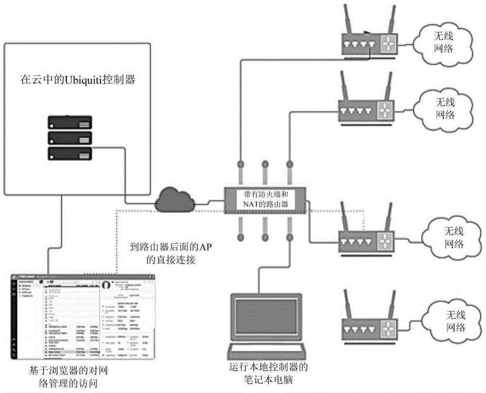
Compact and integrated local key controller devices are used for remote management of networks of wireless devices connected to computer network switches. These devices (including equipment and systems) and their usage methods can provide secure and fully integrated, stand-alone wireless network controllers that can be remotely accessed without compromising the integrity of the network firewall.

Figure 201680002836

Description

Compact and integrated key controller device for monitoring a network
Cross Reference to Related Applications
Priority of U.S. provisional patent application No. 62/233279, entitled "LOCAL AND CLOUD-BASED combined CONTROLLER FOR MONITORING a network" (HYBRID LOCAL AND CLOUD-BASED CONTROLLER FOR MONITORING network), filed on 25/9/2015, the entire disclosure of which is incorporated herein by reference.
Introduction by reference
All publications and patent applications mentioned in this specification are herein incorporated by reference in their entirety to the same extent as if each individual publication or patent application was specifically and individually indicated to be incorporated by reference.
Technical Field
Methods and apparatus (including systems and devices) for monitoring and configuration of Wi-Fi networks for outdoor and indoor locations. These devices and methods are particularly useful for small and large enterprises, especially Wireless Internet Service Providers (WISPS) that use Wi-Fi to provide broadband over the last mile.
Background
Methods of managing Wi-Fi networks (large, medium, or small) may generally include configuring and configuring the network, monitoring the health of the network in real time, and analyzing network data (which may be large amounts of data requiring complex processing and large amounts of processor time) to provide network health indications. Current solutions for network monitoring are generally divided into local and cloud (or remote) based control systems and methods. The method/system of local control may include a local controller (i.e., physical hardware) and/or software installed on a local PC/server. The system administrator may then use the local system to manage the network from within the security of the existing network, such as behind a firewall; this is very secure because it does not require leaving a firewall, however, the intensive processing required may limit the amount of analysis and the size of the network that can be monitored in this way. In short, local controllers are typically within a firewall and are thus good at real-time monitoring, but are limited by available space and computing capacity, thus limiting the number of devices that can be monitored by one entity. Such local systems/methods do not provide a global view of the network and are also not suitable for big data analysis of network data for providing insight due to computational and storage limitations.
In contrast, cloud (remote) based methods/systems typically use a cloud based controller, where all network data is sent to the cloud (remote server) for monitoring/alerting. Due to access to large processors and memory, such cloud/remote based systems and methods are very adept at handling large amounts of data (large networks) and can provide very high levels of analysis, data manipulation, and data storage. Such cloud controllers are good at passive analysis of large data sets, however, they may suffer from network delays that require frequent sending of data for real-time alerts. Remote/cloud-based network controllers and monitors may typically require equipment to push data (which is typically located within one or more firewalls), or they must maintain expensive (and potentially dangerous) open socket connections. Thus, cloud-based controllers may suffer from real-time versus size tradeoffs, typically due to firewalls.
What is needed is a system that combines the advantages of both local and cloud approaches while avoiding or minimizing the above-mentioned problems. In particular, what is needed is a hybrid approach that allows scalable, real-time analysis and background processor intensive analysis, and maintains the integrity of network firewalls. The present invention describes an apparatus and method that addresses these needs.
Disclosure of Invention
The present invention provides a compact and integrated local key controller apparatus for remotely managing a network of wireless devices connected to a computer network switch. These devices (including apparatus and systems) and methods of use thereof may provide a fully integrated, stand-alone wireless network controller that is secure and may be remotely accessed without affecting the integrity of a network firewall.
For example, the present invention provides a compact and integrated local key controller apparatus for remote management of a network of wireless devices connected to a computer network switch. These means may include: a housing; an Ethernet connection configured to connect to the computer network switch, the computer network switch connected to a plurality of network devices behind a firewall, the plurality of network devices including a plurality of wireless access points; a processor located within the housing, the processor configured to: identifying the local key controller device to a remote server (e.g., when the local key controller device is connected to the computer network switch); authenticating a request from a remote computer outside the firewall to communicate with the local key controller device; communicating controller information directly with the remote computer without passing the controller information through the remote server, wherein the controller information includes monitoring information about the network device and computer network switch information; receiving modification information from the remote computer without communicating the modification information through the remote server; and modifying the computer network switch and the network equipment or modifying the computer network switch and the network equipment simultaneously according to the modification information.
As mentioned above, these devices may generally be compact and integrated. For example, in any of these devices, the housing encompasses less than 0.5cm3Volume of (e.g., 0.5 cm)3Or less, 0.4cm3Or less, 0.3cm3Or less, 0.2cm3Or less, 0.17cm3Or less, 0.15cm3Or less, 0.125cm3Or less, 0.11cm3Or less, etc.), wherein the device has a weight of less than 200g (e.g., 200g or less, 175g or less, 150g or less, 125g or less, 110g or less, 100g or less, etc.). These devices may include a processor, but may not include a display screen, display, etc., or user input (beyond a single reset control/button), etc. For example, any of these devices may include a single button configured as a reset button on the housing. Any of these devices may include a memory card slot configured as a fixed removable memory. One or more indicator lights (e.g., LEDs) may be visible on or through the housing.
Typically, the device may receive power from a power over ethernet (PoE) connection or an adapter that provides power in addition to a separate ethernet connection. For example, in some variations, the ethernet connection comprises a power over ethernet (PoE) connection.
Typically, the processor may be configured to communicate controller information (e.g., to a remote computer). The processor may be configured to collect and transmit controller information, wherein the controller information includes one or more of: monitoring information about the network device (including network device name, IP address, connection status (number of connections, etc.), activity, download/upload time); delay of the network; network throughput; radio Frequency (RF) channel information; computer network switch information (including port name, status, transmit/receive (Tx/Rx), PoE performance); RF performance analysis; RF monitoring and device mapping.
Alternatively or additionally, the processor may be configured to modify the computer network switch, the network device, or both the computer network switch and the network device, in accordance with the modification information received from the remote computer; the modification information may include one or more of: network device configuration information, LAN and WLAN group assignments for the network devices, configuration of the network devices, Radio Frequency (RF) band steering, WAN/LAN/VLAN configuration for the computer network switch, and operational mode configuration for one or more ports on the switch.
For example, the present invention provides a compact and integrated local key controller apparatus for remote management of a network of wireless devices connected to a computer network switch. The apparatus may include: a housing; a power-over-ethernet connection configured to connect to the computer network switch, the computer network switch connected to a plurality of network devices behind a firewall, the plurality of network devices comprising a plurality of wireless access points; a processor located within the housing, the processor configured to: identifying the local key controller device to a remote server when the local key controller device is connected to the computer network switch; authenticating a request from a remote computer outside the firewall to communicate with the local key controller device; communicating controller information directly with the remote computer without communicating the controller information through the remote server, wherein the controller information includes one or more of: monitoring information about the network device (including network device name, IP address, connection status (number of connections, etc.), activity, download/upload time); delay of the network; network throughput; radio Frequency (RF) channel information; computer network switch information (including port name, status, transmit/receive (Tx/Rx), PoE performance); RF performance analysis; RF monitoring and device mapping; receiving modification information from the remote computer without communicating the modification information through the remote server; and modifying the computer network switch, the network device, or both the computer network switch and the network device according to the modification information, wherein the modification information includes one or more of: network device configuration information, LAN and WLAN group assignments for the network devices, configuration of the network devices, RF band steering, WAN/LAN/VLAN configuration for the computer network switch, and operating mode configuration for one or more ports on the switch.
The present invention also provides a method of operating any one of the compact and unified local key controller devices according to the present invention, and a method of remotely controlling a network using the compact and unified local key controller device.
For example, a method of remotely controlling a network using a compact and integrated local key controller device may include: connecting the local key controller device to a port of a computer network switch behind a firewall, wherein the computer network switch is connected or configured to connect to a plurality of network devices comprising a plurality of wireless access points; identifying the local key controller device to a remote server; receiving a request from a remote computer external to the firewall to communicate with the local key controller device; authenticating the request; communicating controller information directly between the local key controller device and the remote computer without passing the controller information through the remote server, wherein the controller information includes monitoring information about the network appliance and computer network switch information; communicating modification information from said remote computer to said local key controller device without communicating said modification information through said remote server; and modifying the computer network switch and the network equipment or modifying the computer network switch and the network equipment simultaneously according to the modification information.
In any of these methods, communicating controller information may include displaying a graphical user interface that displays the controller information on the remote computer. As described above, the local key controller device may identify itself to the remote server when connected to the computer network switch.
Receiving the request from the remote computer may include receiving the request in the remote server. Authenticating the request may include providing a secure and private single sign-on (SSO).
Communicating the controller information may include communicating monitoring information about the network device, the monitoring information including one or more of: network device name, IP address, connection status (number of connections, etc.), activity, download/upload time. Alternatively or additionally, communicating the controller information includes communicating one or more of: delay of the network; network throughput; radio Frequency (RF) channel information; computer network switch information (including port name, status, transmit/receive (Tx/Rx), PoE performance); RF performance analysis; RF monitoring and device mapping.
Modifying the computer network switch, the network device, or both the computer network switch and the network device may include modifying according to modification information including one or more of: network device configuration information; LAN and WLAN group assignments for the network devices; a configuration of the network device; a Radio Frequency (RF) band guide; WAN/LAN/VLAN configuration of the computer network switch; and an operational mode configuration of one or more ports on the switch.
For example, the present invention provides a method of remotely controlling a network using a compact and integrated local key controller device, the method comprising: connecting the local key controller device to a port of a computer network switch behind a firewall, wherein the computer network switch is connected or configured to connect to a plurality of network devices comprising a plurality of wireless access points; identifying the local key controller device to a remote server, wherein the local key controller device identifies itself to the remote server when connected to the computer network switch; receiving a request from a remote computer external to the firewall to communicate with the local key controller device; authenticating the request; communicating controller information directly between the local key controller device and the remote computer without communicating the controller information through the remote server, wherein the controller information includes one or more of: monitoring information about the network device, including one or more of: network device name, IP address, connection status (number of connections, etc.), activity, download/upload time; delay of the network; network throughput; radio Frequency (RF) channel information; computer network switch information comprising one or more of: port name, status, transmit/receive (Tx/Rx), PoE performance; RF performance analysis; and RF monitoring and device mapping; communicating modification information from said remote computer to said local key controller device without communicating said modification information through said remote server; and modifying the computer network switch, the network device, or both the computer network switch and the network device according to the modification information, wherein the modification information includes one or more of: network device configuration information, LAN and WLAN group assignments for the network devices, configuration of the network devices, Radio Frequency (RF) band steering, WAN/LAN/VLAN configuration for the computer network switch, and operational mode configuration for one or more ports on the switch.
Drawings
The appended claims set forth the novel features of the invention with particularity. A better understanding of the features and advantages of the present invention will be obtained by reference to the following detailed description that sets forth illustrative embodiments, in which the principles of the invention are utilized, and the accompanying drawings of which:
FIG. 1A is a schematic diagram of one example of a local key controller device connected to a typical network;
FIG. 1B is a schematic diagram of another example of a network including a compact and integrated local key controller device;
FIG. 1C is a schematic diagram of another example of a network including a compact and integrated local key controller device;
fig. 2A is a perspective view of an example of a compact and integrated local key controller apparatus (which may also be referred to herein as a local controller ("key")) for remotely managing a network of wireless devices;
FIGS. 2B, 2C and 2D illustrate side, bottom and top views, respectively, of the device of FIG. 2A;
FIG. 3A is a schematic diagram of an example of a secure, digital non-volatile memory (e.g., a microsD card) that may be used with the device of FIGS. 2A-2D;
FIG. 3B is a schematic diagram of an example of a connector (e.g., an Ethernet cable) that may be used with the devices of FIGS. 2A-2D;
FIGS. 4A-4D are schematic illustrations of one method of connecting and/or installing the device of FIGS. 2A-2D;
FIG. 5 illustrates typical (for illustration only) parameters of the local controller ("key") device shown in FIGS. 2A-2D;
6A-6C illustrate exemplary user interfaces for communicating with one or more local controllers to monitor, control, (including setup) or otherwise analyze and/or provide a network using one or more local controllers ("keys") of the present invention;
FIG. 7 is a schematic diagram of an example of a network including a plurality of local networks (local access points) that may be monitored, controlled, etc. using the apparatus and methods of the present invention;
FIG. 8A illustrates a conventional topology for communication between devices (including devices that are part of a network that communicates with external devices);
FIG. 8B illustrates an example of an alternative topology based on a WebRTC type topology;
FIG. 9 illustrates a series of communication steps using a hybrid point-to-point topology (as may be implemented using the local key controller device of the present invention);
FIG. 10 illustrates one example of a "dashboard" user interface that may be provided by the local key controller apparatus of the present invention to a remote computer/computing device (e.g., cell phone, laptop, tablet, etc.);
FIG. 11 is a schematic view of one example of a map that may be used as part of the user interface provided by the local key controller device of the present invention;
FIG. 12 is a schematic diagram of an example of a user interface displaying device information from the local key controller apparatus of the present invention;
FIG. 13 illustrates an example of client information that may be provided by the local key controller apparatus to a remote computer/computing device in accordance with the present invention;
FIG. 14 is a schematic diagram of an example of a statistics screen of a user interface based on information provided by a local key controller device to a remote computer/computing device;
fig. 15 is a schematic diagram of an example of an exchange detail information screen or panel of a user interface based on information provided by a local key controller to a remote computer/computing device.
Detailed Description
The present invention provides a compact and integrated local key controller apparatus for remote management of a network of wireless devices connected to a computer network switch. These apparatuses (including devices and systems) and methods of use thereof may provide a fully integrated, stand-alone wireless network controller that is secure and may be remotely accessed without affecting the integrity of the firewall of the network.
The local key controller apparatus of the present invention may include an integrated computer and software controller in a very small form factor. For example, the apparatus may include a processor (e.g., a quad-core processor with 1GB of RAM) and may be configured to function as a controller capable of configuring and managing a plurality (2 or more, 3 or more, 4 or more, 5 or more, 6 or more, 10 or more, 20 or more, 30 or more, etc.) of network devices.
Typically, these devices may be directly connected to a switch, router, or composite router and switch, forming a network or part of a network. Thus, the device may be installed behind a network firewall and, after authentication, may be remotely accessed by a remote computer or processor. Authentication may be accomplished by SSO (single sign on) which provides security and privacy. Thus, it is possible to remotely access the switch and/or the plurality of network devices connected to the switch from outside the firewall without the need for a third party, e.g., a hosted cloud service. In some variations, the local key device may be configured to provide monitoring and access control to secure data on the network by establishing direct peer-to-peer communication without communicating information to an intermediary server, such as a cloud server, so that the secure data and network information remain local and the network remains secure.
The apparatus and method of the present invention is also scalable, possibly configured to allow configuration, monitoring and management of network devices from one or more networks from a central control platform. A local key controller device for remote management of a network of wireless devices connected to a computer network switch may be accessible through a standard web browser and may be used to control one or more networks.
For example, fig. 1B and 1C illustrate one example of a compact and integrated local key controller apparatus for remote management of a network of wireless devices connected to a computer network switch. For example, in fig. 1B, the network includes a switch 803 and a secure router 807 that may be connected to the internet 809. The network also includes a plurality of network devices including a plurality of wireless Access Points (APs) 805, 805', 805 "connected to the switch 803. The local key controller device is connected to a portion of the switch 803 via a power over ethernet (PoE) connection. Similarly, FIG. 1C illustrates another example of a network including a plurality of network devices. In this example, the network device includes at least one wireless Access Point (AP)805 (which communicates with one or more wireless clients 811) connected to a switch 803, and one or more wired clients 813 connected to the switch 803, and a plurality of VOIP phones 815. The switch is also shown connected to a server 817. The network includes a network-connected security router 807, the security router 807 being connected to the internet, possibly protected by a firewall. The remote computer 833 may be connected to the network through the local key controller device 801 which is directly connected to the switch 803. The local key controller device may provide convenient network management via a remote computer; the local key controller apparatus may include hardware, firmware, and/or software that allows a network administrator to configure and monitor network devices (and/or switches, and/or routers) using a user interface without the need for separate software or a host. Fig. 7 is another schematic diagram illustrating the use of multiple local key controller devices 705, 705', 705 ", each connected to the network behind a respective firewall and each communicating with a single remote computer that may allow aggregation of data from each local network; communication between each key 701, 701', 701 "and the remote computer 703 may be via the cloud 705, directly (e.g., peer-to-peer once the cloud server connects the two), or a combination of both, as described in more detail below.
The local key controller device of the present invention installed at each network deployment site may provide always-on, private remote monitoring and control. Each point may be accessible through the secure SSO assigned to it. Each local key controller device may have its own network monitoring, configuration, mapping, statistics, and management accounts, which may be aggregated together.
For example, the present invention provides a compact and integrated local key controller apparatus for remote management of a network of wireless devices connected to a computer network switch. These devices may also or alternatively be referred to herein as hybrid local and remote (cloud-based) controller devices for monitoring, analyzing and/or modifying a WiFi network, including switches and network settings. These methods and apparatus may provide real-time monitoring and modification of a network, including real-time network alerts, and may use a local controller (e.g., within a firewall or wall), while allowing logging, analysis, and data mining (within a firewall) to be performed at a remote but authenticated server, without requiring transmission of sensitive information by a remote (cloud) server, or allowing logging, analysis, and data mining to be performed at a cloud-based controller. A cloud-based portal may provide a secure channel for access between remote computers and local controllers (e.g., compact and integrated local key controller devices) to monitor, modify, and configure network devices from anywhere on the network.
Some variations of the method of the present invention may divide network management functions across local and remote computers and/or cloud controllers to provide real-time large-scale monitoring, analysis, and control. Accordingly, these methods and apparatus (e.g., systems and devices, including software) may be referred to as zoned WiFi network management apparatus and methods.
For example, FIG. 1A is a schematic diagram of one example of a local key controller device connected to a typical network. In this example, a local computer (e.g., a laptop) operates as a controller running local controller software and is connected to a network to be monitored/controlled at a computer network switch. The local controller may act as a "key" or "point" and may be integrated into a dedicated compact, lightweight and energy efficient device (compact and integrated local key controller device) that has advantages over separate software (e.g., running on a general purpose computer, as shown in fig. 1A); examples of compact and integrated local key controller devices are described in more detail below in fig. 2A-5. Typically, the local controller comprises a physical connector (e.g. a cable connection) to the network, e.g. a switch/router of any other network device, possibly connected to one or more access points, or comprising one or more access points, Customer Premises Equipment (CPE) or any other device. The key may typically be connected to the router (via, for example, an ethernet connection). The key is thus connected within the firewall of this local network. The key may provide access to a local network (e.g., a laptop or other processor running a local controller interface). The key then communicates with a remote server (e.g., the cloud), which may provide browser-based access for network management.
In the example shown in fig. 1A, the secondary controller or controller client may reside in and/or be connected through a cloud. For example, after connecting a key to a network (e.g., to a switch or router), the key will register itself with the cloud-based controller, possibly using, for example, WebSocket. The key may then provide the cloud controller with STUN/TURN parameters (STUN is an abbreviation for Session Traversal Utilities for NAT, i.e. Session Traversal utility, TURN is an abbreviation for Traversal Using relay around NAT, where NAT refers to network address translation). The local controller may also employ a user account to monitor the domain when logging into the cloud. The cloud controller may then register the STUN/TURN parameters on its STUN/TURN server, and the WebRTC-enabled browser may contact the cloud controller to obtain a list of registered local controllers. In some variations, the cloud may be used to execute (e.g., processor intensive) analysis components from the provided network data. Alternatively, with this architecture, a local controller (e.g., a compact and unified local key controller device) may communicate with an external (remote) computer in a point-to-point relationship, and may perform display (e.g., monitoring, etc.), analysis (including processor intensive analysis), and management, including sending control commands to adjust switches and/or network devices, without transferring any data from the local network to the cloud (including cloud servers), or through the cloud. As used herein, a remote computer may refer to any computing device capable of communicating directly with a compact and integrated local key controller apparatus, including laptops, desktops, wearable computers, smartphones, tablets, and the like.
For example, fig. 8B illustrates an example of a WebRTC type topology for two remotely located peer devices to efficiently exchange data. As described above, any of the devices of the present invention may be configured to allow such direct point-to-point communication between a compact and integrated local key controller device and a remote computer by employing a WebRTC type topology for use with the devices and methods of the present invention. For example, compare fig. 8A with fig. 8B. Fig. 8A illustrates a typical centralized communication topology, where a first network comprising a home computer and an internet service provider is connected through a central server to a remote computer (in this example a smartphone) connected to an independent network (a mobile network operator). In this example, the remote devices (smartphones) communicate in a centralized manner, as indicated by the black arrows, which may lead to reliability risks due to central server failure and increased costs. Although data transmitted between the remote device (telephone) and the home computer (on the first network) may be encrypted and may be protected by a firewall, the transmitted data must pass through a central server, resulting in an actual or perceived security risk. In contrast, the topology shown in fig. 8B is a decentralized topology based on a WebRTC (WebRTC is an abbreviation for "WebReal Time Communication", i.e. internet real Time Communication) architecture, in which there are two types of Communication streams: the dashed arrows represent data exchanged between the local device (behind the firewall) and the remote device (phone) through the central server, which is mainly network address and identity information, while the solid lines represent most local data. Network address and identity information may be referred to as presence data and typically constitutes a small fraction (< 1%) of the data transmitted, which may include information about presence, internet address, identity, authentication, etc. The resulting decentralized topology may be suitable for use with the apparatus and method of the present invention, which when connected to a switch, may communicate with a remote server (e.g., a mediation server) to provide presence data, rather than any user data that would otherwise be protected by a firewall. The remote computer may request communication with the device (e.g., monitoring and/or controlling a network) by contacting the device via the mediation server, and once the remote computer is authenticated, a direct connection between the device and the remote computer may be established, as shown, for example, in fig. 9. In the present example, the first three blocks in the sequence diagram shown correspond to the dashed lines in fig. 8B. They represent a small amount of data in terms of the amount of data transmitted (e.g., < 1%); once point-to-point communication has been established, most of the data transmitted occurs in the fourth box. In this example, the remote computer may be Peer A and the local key controller device may be Peer B (and vice versa).
In practice, locally and physically installed keys may communicate and transfer network data directly to a remote computer in a highly secure manner that maintains the integrity of the network firewall, allows real-time local monitoring, alarming, and reporting, while also allowing remote analysis and storage of historical and related information. In some examples, metadata extracted from the secure network data may be passed to a cloud server for storage and/or further processing; alternatively, the data may be limited to the local computer. In some variations, software on the remote computer (which may be a browser only, or may be dedicated software for communicating with the device of the present invention) may be linked to the key and may communicate directly with the network locally through the key, while still accessing cloud-based information and analysis.
In a variation where the compact and unified local key controller device transmits information to the cloud after installation of the local controller (compact and unified local key controller device), the key may determine (e.g., intelligently determine) which information is sent to the cloud, which may be done within a predetermined (non-real time) period. Processors (e.g., laptop, computer, smartphone, etc.) specifically and securely paired with the key, as well as any number of keys (e.g., other networks or other devices on/in the network) may allow for real-time/local processing.
When the key is first connected to the device and/or network, it may communicate with the cloud (remote processor) to identify itself. The key may send channel information for the key (e.g., through a firewall). The key (compact and integrated local key control device) may then communicate directly with the cloud (e.g., via websocket) and may provide this access to the paired device (e.g., remote computer). When a paired device (e.g., laptop, smartphone, etc.) wants to connect to a controller to, for example, monitor and/or obtain reports and modify network behavior locally/in real time, the cloud server may directly connect the paired device with the key, and the cloud may redirect to both for direct communication, similar to that shown in fig. 8B and 9.
For example, the paired remote computer may communicate with the cloud through a browser (web browser) and may send/receive information from the cloud (e.g., analysis on a network associated with the paired device); the paired device may additionally or alternatively communicate directly with the network in a direct (local or pseudo-local) manner. For some functions (e.g., real-time monitoring/alarming, etc.), the control software may thus communicate directly and securely with a control key (cloud key or compact and integrated local key controller device) that may look like a dongle or other device connected to the network hardware (e.g., router, switch, access point, CPE (customer premises equipment), etc.). This key may first introduce itself to a remote (e.g., cloud) server and, upon initialization, may be employed by a user account associated with a particular user/paired device (e.g., laptop). The SSO of the paired device/user may be added on the cloud to let the user access the key inside the firewall.
The user may then interact within the firewall (e.g., in real-time) using a local (compact and integrated local key controller device) device, but may establish a communication session through the cloud. Alternatively, as described above, in a variant, the compact all-in-one local key controller device may provide data to a remote (cloud) server to provide cloud-specific content, such as more analytic data about overall network health. Alternatively or additionally, the cloud portion (e.g., cloud controller) may redirect the paired user/device to the correct key, and the locally installed key may provide local information to the paired remote computer, either without sending network data/information to the cloud for processing and/or storage (in a first peer-to-peer configuration), or with sending network data/information to the cloud for processing and/or storage (in a cloud analysis mode), or in a hybrid configuration, with some network data/information sent to the cloud for processing and/or storage, with some network data/information simply remaining in the remote computer. Thus, the key device may be intelligent enough to send the cloud the information needed for analysis, or to limit the data (secure network data) to a remote computer. In some variations, the device may be configured to allow a local user to select the operating mode in which the device operates.
Thus, in practice, a user may configure the system to include or exclude clouds (e.g., transmission of data into or out of the clouds), and/or may determine, limit, or prevent the type of data (or aggregation, averaging, grouping, etc. of data) to be transmitted to the clouds, and/or the timing of data transmission to the cloud servers. The term "cloud" as used herein may refer to any remote processor, computer, system, etc., including in particular a remote server. A user, when, for example, installing a key on a network or network device, may configure the key to determine permissions (e.g., paired devices) that may allow or make a pair. The key may be limited to a single paired device. Further, as described above, the key may determine how to partition information (e.g., those information sent to the cloud and/or retained locally).
Fig. 2A-2D illustrate one example of an embodiment of a key (which may also be referred to as a point or local key controller device) of the present invention. Fig. 2A shows a front perspective view. In this example, the device may include an indicator 202 (e.g., an LED) that displays status (default, busy/process, normal operation, etc.). Fig. 2B illustrates a top view including an indicator, which may be one or more colored LEDs, representing a status. Fig. 2C shows a view of the top panel showing the connectors (ethernet ports) for connecting to the network. A connector as shown in fig. 3B may be used. Fig. 2D shows a bottom panel of the local key controller device, including control (e.g., reset button), spare connector (micro-USB), and memory card (e.g., microSD) ports. A first connector (e.g., an ethernet port) may be used (e.g., a gigabit ethernet port) to connect to a power source and may be connected to a network device such as a LAN and/or a DHCP server. The power may be supplied through, for example, a power over ethernet (PoE) switch. The control button may be, for example, a reset button or switch that may be used to restore factory default settings and/or reset the device. The second connector shown is a micro-USB connector, which may be typically used to provide an alternative power source in situations where, for example, PoE is not available. Fig. 4D illustrates such a case.
Fig. 4A-4D illustrate a variation of a method of connecting a key 400 to a network. In fig. 4A, the key 400 is first connected to a connector/cable (ethernet cable) at a connector port on the key. In fig. 4B, a removable memory card 405 (microSD shown in fig. 3A) is inserted into a receiver (shown as a microSD slot on a key). The other end of the cable is then connected to a port on a network switch or other device. In fig. 4C, the key is connected to a port on the network switch. The device may then be powered up and configured. For example, as shown in FIG. 4D, the device may be connected to a USB power source, such as a USB cable connected to a wall cord. FIGS. 1B and 1C, discussed above, illustrate the use of the local key controller devices shown in FIGS. 2A-4D in various network environments. FIG. 5 illustrates example features of one example of a local key controller device. These parameters (including size, weight, network interface, power supply, maximum power consumption, operating temperature, etc.) are for illustration only, and these devices may typically be small, lightweight, and may be easily connected to a network (e.g., a switch or other component) and fixed with a network component, e.g., in a rack.
The local key controller apparatus may have pre-installed control user interface software that may be accessed by the remote computing device (e.g., laptop, phone, etc.) with which it is to be paired. For example, it is possible to access the software by connecting the devices to be paired (which include an ethernet connection) to the same Layer-2 network as the key. The key may be set to DHCP by default and thus attempt to obtain an IP address; it is possible to assign an IP address (e.g., by a subscriber or DHCP server, etc.). Alternatively, the device may be pre-assigned an IP address. The device to be paired may then connect to the IP address of the key, possibly through an internet browser.
As shown in fig. 6A-6C, the key may be paired and/or initialized using the user device (paired device). For example, the user may enter a name and password (at the IP address of the key) and log in the key, as shown in FIGS. 6A-6B. FIG. 6C illustrates an example of a UI displaying a device connected to a key; additional devices may be discovered and added and/or accessed by the paired device (via the key). For example, a device may be added by an IP address, or by discovering the device (e.g., scanning for network devices). For example, a device may be identified by scanning/searching a range of IP addresses. The device identified by the key may be connected with the login credentials, setting up a network device for the key that can/will be viewed/monitored/controlled. As described above, the key may also be configured to determine what information to add/push to the cloud (remote server), including selecting to opt out of such information (although in some variations the lowest amount of information, such as device presence and basic state of such devices, etc., may be transmitted even when opt out). It is possible to manage the devices "locally" by direct communication between the paired device and the key.
It is often possible to manage a network using a management system that typically requires a software-based "controller" to run on a computer, at least for initial setup of the computer. Controller software typically must run if you want to be able to see what devices are connected, disconnect devices that use too much data bandwidth, issue credentials to gain internet access, and many other features. Prior to the present invention, in most cases, users had to run the controller software locally on a Window or Linux computer, or according to a "cloud" based service that allows the controller software to be set up and accessed from anywhere. .
The compact and integrated local key controller device of the present invention may provide an alternative intermediary solution. The compact and integrated local key controller device of the present invention is typically configured as a miniature (that occupies very little resources) computer that runs the controller locally, e.g., on a switch and/or router. Users typically plug compact and all-in local key controller devices into ports on the network switches and do not need to run separate computers constantly with the front controller software. The compact and unified local key controller may include its own operating system (e.g., Linux), controller logic (e.g., software, hardware, and/or firmware), memory (e.g., 8GB Micro SD card or other removable and/or integrated memory), and be configured with the ability to enable the controller to be accessed remotely first from a remote server that needs to handle only a minimal amount of communications (e.g., see fig. 8B and 9 above), while allowing direct point-to-point communications between the compact and unified local key controller device and a remote computer (which may be a laptop, desktop, tablet, and/or smartphone).
When a device is installed, it may be provided with a static IP address, a user-defined IP address, or it may be assigned an IP address (e.g., DHCP may assign an IP address). Compact and all-in-one local key controller devices may be configured as both an operating system and a network controller; multiple sets of login credentials may be used for each. A compact and integrated local key controller device may be plugged into an open port in an exchange on a network. The compact and integrated local key controller device may use a power port (e.g. industry standard 48v POE) or a 5v USB type power supply as used for charging portable devices such as iphones, Android (Android) tablets and USB interfaces (e.g. with Micro USB connectors that may be plugged into the compact and integrated local key controller device). In some variations, the default IP address of the compact and unified local key controller device is static; alternatively, the DHCP server (e.g., router) may assign a different address. The IP address may then be used by a browser (e.g., on a 192.168.1.x network) and then may be connected to a user interface to initially set up a compact and integrated local key controller device.
The compact and all-in-one local key controller device may be configured to set a permanent IP address and password, and optionally a time zone. It is possible to use a static (fixed) IP address by picking an address that is outside the range of addresses distributed to portable devices. Thereafter, starting with the browser, the IP address of the compact and all-in-one local key controller device may be used in the remote device to communicate (see, e.g., fig. 9) and establish point-to-point communication between the device and the local computer displaying the data provided by the network, switch and/or client device and transmitted directly from the device.
Any local key controller device of the present invention may be configured to provide a comprehensive overview of network health, including one or more indicators. In particular, the local key controller device of the present invention may provide a graphical network dashboard including indicators that monitor important indicators of the network, allowing administrators to make adjustments as needed to improve the performance of the network. The dashboard may provide a visual representation of the network state and provide basic information about each network segment. The local key controller device may also provide detailed analysis. The analysis may be configured to allow monitoring of a large group of users and expedite troubleshooting, including LAN/WLAN groups.
For example, any local key controller apparatus of the present invention may provide flexible configuration for large deployments, including creating multiple LAN and WLAN groups and assigning their respective network devices.
The local key controller device of the present invention may also facilitate Wi-Fi management to allow remote users to provide wireless Access Points (APs), configure wireless networks, formulate networks, and manage system traffic. The local key controller device may provide Radio Frequency (RF) monitoring and device mapping of the network, detailed RF performance analysis of the network, guided support of the network, and guest entry/hotspot support. The local key controller device of the present invention may also provide router and switch management, including providing gateways and switches, and the following configurations: WAN/LAN/VLAN configuration, operating mode (switching, monitoring or aggregation) of each port, PoE settings of each port, jumbo frame and flow control services, and/or monitoring and analysis performance of each port of the switch.
As mentioned above, the local key controller device may also provide a Wi-Fi RF map to monitor the wireless AP, analyzing the surrounding RF environment. The local key controller device may also or alternatively provide statistical data of the operation of the network or components of the network. For example, the user interface displayed by the remote computer in communication with the local key controller device may include a data analysis page that provides a visual representation of the network terminal and the amount of network communications performed by the switch and networked APs.
Example 1: local key device
The compact and integrated local key controller device may be configured such that it (e.g., controller software, hardware, and/or firmware) may have a browser-based interface that facilitates configuration and management; such a user interface may be displayed on a remote (or local) computer in communication with the compact and integrated local key controller device. For example, in some variations, the compact and integrated local key controller device is connected to an exchange as described above and is remotely accessed. To access the user interface, the user may, for example: a controller application is launched and logged in to authenticate the user and a remote (or local) computer to the compact and unified local key controller device. In case the user (or remote computer) is valid and/or the authentication is successful, the compact and all-in-one local key controller device may safely and directly (point-to-point) send information to the remote computer and receive control instructions from the remote computer.
In some variations, the user interface of the compact and all-in-one local key controller device may display information on multiple screens or pages that may be accessed through graphical navigation (e.g., navigation bars or menus). For example, the apparatus may include controller software, hardware or firmware that provides six or more main pages (e.g., "dashboards" that show summary or general information about the network or components of the network), maps (that graphically show network information), device information areas (that provide information about the wireless devices (e.g., access points) that make up the network), information pages for clients (that show information about client devices that use the network), statistics (that show statistics about the operation of the network), and insights (that show different types of status information).
The user interface may include generic options that are accessible from anywhere in the interface, such as refresh (e.g., updating information on the screen, and/or adjusting refresh intervals). The user interface may also allow switching between different networks, which are referred to as sites. Each site may have its own configuration, maps, statistics, visitor entries, and site administrator accounts. Multiple sites may be logically separated and the initial site may be referred to as the "default". A site profile may be displayed to show the available list. Each site may display: name (name of station), WAN connection status, LAN (wired network connection status), active display (number of wired devices active), inactive display (number of wired devices inactive), pending display (number of wired devices pending), WLAN (wireless network connection status), user display (number of wireless users S and wired users), visitor display (number of wireless and wired visitors), etc. It is also possible to select the display format (time/date, etc.).
A new site (new network) may be created or added so that a single remote computer may be simultaneously connected to multiple local key controller devices.
May include an event label displaying a series of recent events, along with corresponding device icons, device names, messages, dates, and times. A property panel may be displayed and information related to the selected device may be presented in a pop-up window in the panel. The information varies according to the type of device. The filter may be used to filter recent events according to a specified time period (e.g., last 1 hour, last 8 hours, last 24 hours, last 48 hours, 7 days, 2 weeks, or 30 days, etc.). One or more of the following filters may be employed: all (showing all recent events), only administrator (showing administrator's recent events), only LAN (showing wired network's recent events), only WLAN (showing wireless network's recent events), etc.
When there are new alarms, an icon may be presented showing the number of new alarms, and the alarm icon may show a series of important events, along with the corresponding device icon, device name, message, date and time.
Other configuration information for the display and device may also be set. For example, site configuration (site name change may set the name of the site), country (select the appropriate country), time zone (select the appropriate time zone), etc. An automatic upgrade field may be selected; when it is enabled, the device controller will automatically upgrade the firmware when an update is available. It is also possible to control LEDs (indicators) on the device; when it is activated, the LED on the device will light up. When disabled, the LED will be off. The alert selection may allow the option to enable an alert email to be sent to the administrator's mailbox address. The speed test may be enabled to run a periodic speed test. In some variations, DPI (deep packet inspection) and/or SPI (status packet inspection) may be used for traffic analysis. The DPI engine may keep track of which application (and IP address) is using the most bandwidth. When VOIP ports are remapped to WAN2 ports, port remapping control may be used. And the uplink connectivity monitoring control may monitor the uplink of the managed (wired or wireless) AP by checking to see if gateway/custom IP is achieved. The monitor and wireless uplink performance may be enabled by default. It is possible to enable a default gateway by default so that all managed APs will use the AP's gateway, which provides IP information specified via DHCP or statically.
The dashboard screen may provide a visual representation of the network status. Fig. 10 is an example of a dashboard screen. It is possible to provide each node with basic information: latency, throughput, WAN, LAN, WLAN, etc. It is possible to display the delay value from the latest speed test. The display may be color coded to indicate the status: for example, the security gateway is active and the speed test is available (black); the speed test is not available because it requires an active security gateway (red), etc. It is possible to display the throughput from the latest speed test. The monitor may be color coded to indicate the status: the security gateway is active and the speed test is available (black); the speed test is not available because it requires an active security gateway (red), etc.
Status information may be displayed, including current status information, such as a gateway (showing the IP address of the service provider's gateway); DNS (displays IP addresses of Domain Name System (DNS) servers); IP (showing the internet IP address of the security gateway); uptime (showing the length of time that the internet connection has been active); latency (showing the amount of time a data packet travels from the security gateway to the gateway of the service provider); upload (show upload rate of your internet connection); download (show download rate of your internet connection), etc.
As described above, it is possible to display the results of the most recent speed test, including: last run (showing duration since last speed test), delay (showing amount of time a packet is transmitted from the security gateway to the gateway of the service provider); uploading (displaying the uploading speed); download (display download speed)
The WAN indicator may (graphically) show basic details of the security gateway. For example, green may indicate that the WAN connection is active, red may indicate that the WAN connection is inactive, and so on; active devices (showing the number of gateway devices employed and active); inactive (showing the number of gateway devices employed but inactive); pending (display number of gateway devices pending); status information is displayed that may provide basic details of the wired network. LAN IP may show the local IP address of the security gateway, the clients (showing the total number of local clients); upload (show upload rate of your internet connection); download (show download rate of your internet connection), etc.
The LAN indicator may show basic details of the wired network, e.g., the wired network is active (green); the wired network is inactive (red), active devices (showing the number of wired devices employed and active); inactive (showing the number of wired devices employed but inactive); pending (showing the number of wired devices pending); status information, for example: gateway (showing internet IP address of security gateway), user (showing number of clients connected to wired network); a guest (showing the number of clients connected to the guest's wired network); switches (showing the number of switches managed at this site); downloading (showing the download rate of the wired network); upload (showing the upload rate of the wired network).
The WLAN display may provide basic details of the wireless network, such as: (green) wireless networks are active; (red) wireless networks are inactive, active devices (showing the number of APs employed and active); inactive (showing the number of APs employed but inactive); pending (showing the number of APs pending); it is possible to display status information: a user (showing the number of clients connected to the primary wireless network); a guest (displaying the number of clients connected to the guest wireless network); AP (showing the number of AP machines managed on this site); download (display download rate of wireless network); upload (display upload rate of wireless network).
The controller may also provide information related to download throughput and latency, upload throughput and latency. Devices on the 2.4GHz channel (the 2.4GHz channel occupancy graph shows the channel usage for the 2.4GHz device, showing each device showing a blue square area in its channel); the device on the 5GHz channel shows a 5GHz channel occupancy chart showing channel usage for the 5GHz device.
The device user interface may also include device (e.g., network device) related information including the amount of communication, the number of gateway devices (WANs), the number of wired devices (LANs), the number of wireless devices (WLANs), etc., and may also display client information (the number of network clients, the amount of communication, the type, etc.).
As described above, packet inspection information (e.g., DPI) may be provided that includes traffic volume, traffic volume identified as streaming media, traffic volume identified as network protocol, network-related traffic volume, security update traffic volume, and the like.
As mentioned above, the controller software of the apparatus of the present invention may allow a user to upload custom map images of a location, or to use a map for visual representation of a network (e.g. a GOOGLE map). See, for example, fig. 11. When the controller application is first launched on the remote computer, a default map may be displayed. It is possible to add customized maps by uploading maps. The device may then be placed on a map, and the status of the device shown on the map may be indicated graphically by color and/or icons. The map scale may be adjusted or may be adjustable.
The device screen (see, e.g., fig. 12) may display a list of devices that are discovered by the controller. The user may select any of the column headings to change the list order and may employ filters to view the display (e.g., all devices, gateway/switch, AP, VoIP phone, etc.). The profile may show the number of clients, the amount of data downloaded, the amount of data uploaded, and the channel settings, the configuration may show the radio settings for the WLAN and 2.4GHz and 5GHz radio bands, and the performance may show the number of 2.4GHz and 5GHz clients, the total transmission rate, the total reception rate, the transmission rates in the 2.4GHz and 5GHz bands, and the channel settings.
The device display may display device name, IP address, status, model, version, and uptime columns; gateway/switch (display device name, IP address, status, model, download and upload fields); AP profile (display device name, IP address, status, model, client, download, upload, and channel bar); AP settings (display device name, status, version, WLAN2G, WLAN5G, Radio2G, and Radio5G columns); AP capabilities (display device name, IP address, status, 2G client, 5G client, TX, RX, TX 2G, TX 5G and channel bar); all columns (device name, MAC address, IP address, status, model, version, upload time, client, down, WLAN2G, WLAN5G, Radio2G, Radio5G, 2G client, 5G client, TX, RX, TX 2G, TX 5G, and channel columns); and/or all (all device types are shown). The status may indicate connected, disconnected, awaiting approval, adopted, upgraded, managed by other devices, or individual. A restart control may be included that allows the user to select command information from the remote computer to the device to restart the apparatus. Other commands may include: locate (on a map) (to ring the phone, etc.), upgrade (upgrade firmware/software in the device), adopt (with the device pending approval in the presence of the status), etc.
The client screen (see, e.g., fig. 13) may display a series of web clients. The user can click on any column header to change the list order. Fig. 13 illustrates an example of a client screen. The user may apply a filter to such a display. For example: all (all clients are displayed regardless of the connection type); wireless (displaying all wireless clients); wired (all wired clients are shown). A second stage filter may be used. The data may be sorted or searched. Examples of the data provided include: name (showing the host name, alias, or MAC address of the connected client the user can click on the name to get additional details); hostname (showing the hostname of the connected client); MAC address (showing MAC address of connected client); IP address (showing the IP address used by the client); an 802.1x identification (showing an identification for 802.1x authentication); 802.1x VLANs (VLANs or virtual local area networks showing identification for 802.1x authentication); status (showing authentication of all authenticated guests, or pending of guest pending authentication); network (indicating which local network to use); AP/Port (for wireless clients, the name of the connected AP or port is displayed, which the user can click on to obtain additional details; for wired clients, the name of the network device used by the client and the number of ports are displayed, which the user can click on to obtain additional details); channel (showing the channel used); PHY mode (an icon showing the wireless standard and frequency band used by the signal, and possibly whether the device uses power saving mode, e.g., 11na (5GHz), 11ac (5GHz), 11ng (2.4GHz),11b (2.4GHz), etc.); signal (display signal strength level and signal type); TX rate (showing the total TX (transmit) rate); RX rate (showing total RX (received) rate); activity (showing the relative level of activity per client); download (display total amount of data downloaded by client); uploading (displaying the total amount of data uploaded by the client); uptime (shown as the amount of time that the client has been connected for this session), etc. Further: the IP address displays the IP address used by the client; the connection indicates which network is used. If the connection is wireless, the wireless network name or SSID will be displayed; the AP/port indicates which AP or switch to use; the activity displays the relative level of activity for each client; downloading and displaying the total quantity downloaded by the client; uploading and displaying the total amount of data uploaded through the client; the normal operating time is shown as the amount of time that the client has connected for this session.
In addition, the remote computer may be operable to select one or more commands to modify the network based on such information, such as: restrictions-restrict client access to the network (click through to turn on the client), RECONNECT (click through to connect the wireless client; user can click on RECONNECT to kick off the client, which is usually quick connect back; which is useful for troubleshooting or resolving problematic wireless connections); unauthorized/authorized (visitor available) (click AUTHORIZE to remove the authentication of visitor access and disconnect the visitor, or click on pending authentication for the visitor
Figure GDA0002424402830000221
) And the like.
The statistical screen may provide a visual representation of client and network traffic connected to the managed network, such as to a remote computer connected from the local key controller device of the present invention. FIG. 14 illustrates an example of a statistics screen of the present invention. Two views can be used: profile (a default view describing wireless client and network traffic) and traffic status (describing network traffic used by the application).
Multiple graphs may be selected to display various information, including (total) number of clients, quick clicks, views of most active APs (e.g., name and/or MAC address, total amount of data downloaded and/or uploaded), most active clients (e.g., name and/or MAC address, total amount of data downloaded and/or uploaded), most important clients at all times (e.g., name and/or MAC address, total amount of data downloaded and/or uploaded), current usage: recent activity of the most important access points (number of clients, traffic, etc.), traffic statistics, overall traffic, etc.
The switch display (e.g., hyperlink) may be opened in the property panel or as a separate pop-up window as part of the switch's detailed information window. The property panel may present information about each selected device as a pop-up window in this panel. The panel or screen may include: display (click to display device information); icons (icons of display devices; the icons may change with model changes); status (displayed to indicate device status, e.g., awaiting approval, available, connected, managed by other devices (e.g., not controlled by the current controller), unconnected, etc.). The panel may also include a name/MAC address (device name or MAC address of the display device); restart control (restarting the selected device); positioning control (flashing the LED on the device and the device icon on the map so that the user can position them; the LED may flash until the position button is clicked again); upgrade control (click to upgrade device), etc.
The profile display may be used to display device details, connection details, and uptime. For example, for the uplink: MAC address (name or MAC address of the uplink device is displayed; the user can click on the name to get additional details); speed (shown at connection speed in Mbp); duplex (display mode: full duplex or half duplex); downloading Pkts/Bytes (showing the amount of data downloaded in packets and Bytes); uploading Pkts/Bytes (the amount of uploaded data is shown in packets and Bytes); activity (activity level is shown in bytes per second), etc.
The profile may show any of the following: MAC address (showing the MAC address of the switch or a unique hardware identifier); model (showing the model name of the switch); version (showing version number of firmware of the switch); IP address (showing IP address of switch); power consumption (showing the amount of power used by the switch); temperature (showing the general temperature of the switch); fan level (fan level from 0 to 3 if the switch has a fan; fan level is not shown if the switch has no fan); normal operating time (duration showing that the switch has been running without interruption).
The user interface may also be configured to display one or more ports (e.g., a user may expose and control ports of the switch. for example, FIG. 15 shows an example of a display that may be displayed on a remote computer based on information provided by the device; a user may select an input from this screen or an associated screen to modify the activity of the network, including the network switch. for example, the user interface may display one or more of the ports (showing the number of connected ports); the device (showing the name or MAC address of the downlink device.) you may click on the name to get additional details); model (model showing downlink device); status (display connection speed and duplex mode).
For example, a user may display and control the ports of the switch by, for example, selecting a port display to display port names, status, TX and RX throughput, PoE settings, and network/VLAN.
The user may click on a button to perform a desired action, such as: edit (click to change port configuration), restart (click to restart connected device), etc. A user may display and modify a port configuration to switch, reflect, or aggregate one or more ports.
When a feature or element is referred to herein as being "on" another feature or element, it can be directly on the other feature or element or intervening features and/or elements may also be present. In contrast, when a feature or element is referred to as being "directly on" another feature or element, there are no intervening features and/or elements present. It will also be understood that when a feature or element is referred to as being "connected," "attached," or "coupled" to another feature or element, it can be directly connected, attached, or coupled to the other feature or element or intervening features and/or elements may be present. In contrast, when a feature or element is referred to as being "directly connected," "directly attached" or "directly coupled" to another feature or element, there are no intervening features and/or elements present. Although described and illustrated with respect to one embodiment, the features and elements so described or illustrated may be applied to other embodiments. It will also be appreciated by those skilled in the art that references to a structure or feature that is "adjacent" another feature may have portions that overlap or are derived from the adjacent feature.
Spatially relative terms, such as "below …," "below …," "below," "above …," "above," and the like, may be used herein to facilitate describing one element or feature's relationship to another element or feature as illustrated in the figures. It will be understood that the spatially relative terms are intended to encompass different orientations of the device in use or operation in addition to the orientation depicted in the figures. For example, if the device in the figures is turned over, elements described as "below" other elements or features would then be oriented "above" the other elements or features. Thus, the exemplary term "below" can encompass both an orientation of above and below. The device may be oriented in different distinct directions (rotated 90 degrees or at other orientations) and the spatially relative descriptors used herein interpreted accordingly. Similarly, terms such as "upwardly," "downwardly," "vertical," "horizontal," and the like are used herein for illustrative purposes only, unless specifically indicated otherwise.
Although the terms "first" and "second" may be used herein to describe various features/elements (including steps), these features/elements should not be limited by these terms unless otherwise specifically indicated. These terms may be used to distinguish one feature/element from another feature/element. Thus, a first feature/element described below could be termed a second feature/element, and similarly, a second feature/element discussed below could be termed a second feature/element, without departing from the scope of the present invention.
In general, any apparatus and method of the present invention should be understood as being inclusive, but may alternatively be exclusive of all or a partial subset of the components and/or steps, and may be expressed as "comprising" or alternatively "consisting essentially of" the various components, steps, sub-components, or sub-steps.
As used in the specification and claims, including as used in the examples, unless expressly specified otherwise, all numbers may be read as having the prefix "about" or "approximately", even if such terms are not expressly stated. The phrase "about" or "approximately" may be used in describing size and/or position to indicate that the stated value and/or position is within a reasonably expected range of values and/or positions. For example, a numerical value may have a value of +/-0.1% of the set point (or range of values), a value of +/-1% of the set point (or range of values), a value of +/-2% of the set point (or range of values), a value of +/-5% of the set point (or range of values), a value of +/-10% of the set point (or range of values), and the like. Any numerical value given herein should also be understood to encompass approximations of the numerical value unless the context clearly dictates otherwise. For example, if the value "10" is disclosed, then "about 10" is also disclosed. Any numerical range recited herein is intended to include all sub-ranges subsumed therein. It will also be understood that when a value is disclosed, the values "less than or equal to," greater than or equal to, "and possible ranges between the values are also disclosed, as appropriate to one of ordinary skill in the art. For example, if a value discloses a value of "X," then "X is less than or equal to" and "X is greater than or equal to" are also disclosed (e.g., where X is a numerical value). It should also be understood that in the present application, the data is provided in a variety of different formats and represents end points and start points, as well as ranges for any combination of data points. For example, if a particular data point "10" and a particular data point "15" are disclosed, it is understood that values greater than, equal to, less than, equal to, and equal to 10 and 15, and between 10 and 15, are also considered disclosed. It is also understood that each unit between two particular units has also been disclosed. For example, if 10 and 15 are disclosed, then 11, 12, 13, and 14 are also disclosed.
Although various illustrative embodiments have been described above, any number of variations may be made in the various embodiments without departing from the scope of the invention as described in the claims. For example, the order in which the various method steps described are performed may be changed from time to time in alternative embodiments, and in other alternative embodiments, one or more method steps may be skipped. Optional features of various apparatus and system embodiments may or may not be included in some embodiments. Accordingly, the foregoing description is provided primarily for the purpose of illustration and should not be construed as limiting the scope of the invention, which is set forth in the following claims.
The examples and illustrations contained herein show, by way of example and not by way of limitation, specific embodiments that implement the subject matter of the present invention. As previously mentioned, other embodiments may be utilized and derived, and it is understood that structural and logical substitutions and changes may be made without departing from the scope of this disclosure. Such embodiments of the inventive subject matter may be presented herein, individually or collectively, by the term "invention" merely for convenience and without intending to voluntarily limit the scope of this application to any single invention or inventive concept if more than one is in fact disclosed. Thus, although specific embodiments have been illustrated and described herein, any arrangement calculated to achieve the same purpose may be substituted for the specific embodiments shown. This disclosure is intended to cover all adaptations and variations of the respective embodiments. Combinations of the above embodiments, and other embodiments not specifically described herein, will be apparent to those of skill in the art upon reviewing the above description.

Claims (25)

1.一种紧凑型和一体化的本地钥匙控制器装置,用于对连接至计算机网络交换机的无线设备的网络进行远程管理,该装置包括:1. A compact and integrated local key controller device for remote management of a network of wireless devices connected to a computer network switch, the device comprising: 壳体;case; 以太网连接,其配置为连接至所述计算机网络交换机,所述计算机网络交换机连接至在防火墙后面的多个网络设备,该多个网络设备包括多个无线接入点;an Ethernet connection configured to connect to the computer network switch, the computer network switch connected to a plurality of network devices behind a firewall, the plurality of network devices including a plurality of wireless access points; 处理器,其位于所述壳体内,所述处理器配置为:a processor located within the housing, the processor configured to: 向远程服务器标识所述本地钥匙控制器装置;identifying the local key controller device to a remote server; 对来自所述防火墙外部的远程计算机的与所述本地钥匙控制器装置通讯的请求进行认证;authenticating requests from remote computers external to the firewall to communicate with the local key controller device; 直接与所述远程计算机传送控制器信息,而无需通过所述远程服务器传递所述控制器信息,其中,所述控制器信息包括关于所述网络设备的监控信息和计算机网络交换机信息;transmitting controller information directly with the remote computer without passing the controller information through the remote server, wherein the controller information includes monitoring information about the network device and computer network switch information; 从所述远程计算机接收修改信息,而无需通过所述远程服务器传递所述修改信息;以及receiving modification information from the remote computer without passing the modification information through the remote server; and 根据所述修改信息,修改所述计算机网络交换机、修改所述网络设备、或同时修改所述计算机网络交换机和网络设备。Based on the modification information, the computer network switch is modified, the network device is modified, or both the computer network switch and the network device are modified. 2.根据权利要求1所述的装置,其特征在于,所述壳体的体积小于0.2cm3,并且所述装置的重量小于150g。2 . The device of claim 1 , wherein the volume of the housing is less than 0.2 cm 3 , and the weight of the device is less than 150 g. 3 . 3.根据权利要求1所述的装置,其特征在于,所述装置还包括在所述壳体上的单个按钮,该按钮配置为复位按钮。3. The device of claim 1, further comprising a single button on the housing configured as a reset button. 4.根据权利要求1所述的装置,其特征在于,所述装置还包括存储卡插槽,该存储卡插槽配置为固定可拆除的存储器。4. The apparatus of claim 1, further comprising a memory card slot configured to hold a removable memory. 5.根据权利要求1所述的装置,其特征在于,所述装置还包括在所述壳体上可见的指示灯。5. The device of claim 1, further comprising an indicator light visible on the housing. 6.根据权利要求1所述的装置,其特征在于,所述以太网连接包括以太网供电(PoE)连接。6. The apparatus of claim 1, wherein the Ethernet connection comprises a Power over Ethernet (PoE) connection. 7.根据权利要求1所述的装置,其特征在于,所述处理器配置为在所述装置连接至所述计算机网络交换机时,向所述远程服务器标识所述本地钥匙控制器装置。7. The apparatus of claim 1, wherein the processor is configured to identify the local key control apparatus to the remote server when the apparatus is connected to the computer network switch. 8.根据权利要求1所述的装置,其特征在于,所述处理器配置为传送控制器信息,其中所述控制器信息包括以下中的一个或多个:关于网络设备的监控信息,其包括以下中的一个或多个:网络设备名称、IP地址、连接数量、活动性、下载/上传时间;网络的延迟;网络吞吐量;射频(RF)信道信息;计算机网络交换机信息,其包括以下中的一个或多个:端口名称、状态、发送/接收(Tx/Rx)、PoE性能;RF性能分析;以及RF监控和设备映射。8. The apparatus of claim 1, wherein the processor is configured to communicate controller information, wherein the controller information includes one or more of the following: monitoring information about network devices, including One or more of the following: network device name, IP address, number of connections, activity, download/upload time; latency of the network; network throughput; radio frequency (RF) channel information; computer network switch information, including the following One or more of: port name, status, transmit/receive (Tx/Rx), PoE performance; RF performance analysis; and RF monitoring and device mapping. 9.根据权利要求1所述的装置,其特征在于,所述处理器配置为:根据所述修改信息,修改所述计算机网络交换机、修改所述网络设备、或者同时修改所述计算机网络交换机和网络设备,所述修改信息包括以下中的一个或多个:网络设备配置信息、所述网络设备的LAN和WLAN组分配、所述网络设备的配置、射频(RF)带引导、所述计算机网络交换机的WAN/LAN/VLAN配置、以及所述交换机上的一个或多个端口的运行模式配置。9 . The apparatus according to claim 1 , wherein the processor is configured to: modify the computer network switch, modify the network device, or modify the computer network switch and the computer network switch simultaneously according to the modification information. 10 . a network device, the modification information comprising one or more of: network device configuration information, LAN and WLAN group assignments for the network device, configuration of the network device, radio frequency (RF) band steering, the computer network WAN/LAN/VLAN configuration of the switch, and operational mode configuration of one or more ports on the switch. 10.一种紧凑型和一体化的本地钥匙控制器装置,用于对连接至计算机网络交换机的无线设备的网络进行远程管理,该装置包括:10. A compact and integrated local key controller device for remote management of a network of wireless devices connected to a computer network switch, the device comprising: 壳体;case; 以太网供电连接,其配置为连接至所述计算机网络交换机,所述计算机网络交换机连接至在防火墙后面的多个网络设备,该多个网络设备包括多个无线接入点;a Power over Ethernet connection configured to connect to the computer network switch, the computer network switch connected to a plurality of network devices behind a firewall, the plurality of network devices including a plurality of wireless access points; 处理器,其位于所述壳体内,所述处理器配置为:a processor located within the housing, the processor configured to: 当所述本地钥匙控制器装置连接至所述计算机网络交换机时,向远程服务器标识所述本地钥匙控制器装置;When the local key controller device is connected to the computer network switch, identifying the local key controller device to a remote server; 对来自所述防火墙外部的远程计算机的与所述本地钥匙控制器装置通讯的请求进行认证;authenticating requests from remote computers external to the firewall to communicate with the local key controller device; 直接与所述远程计算机传送控制器信息,而无需通过所述远程服务器传递所述控制器信息,其中,所述控制器信息包括以下中的一个或多个:Directly communicate controller information with the remote computer without passing the controller information through the remote server, wherein the controller information includes one or more of the following: 关于网络设备的监控信息,其包括以下中的一个或多个:网络设备名称、IP地址、连接数量、活动性、下载/上传时间;Monitoring information about network devices, including one or more of the following: network device name, IP address, number of connections, activity, download/upload time; 网络的延迟;network delay; 网络吞吐量;network throughput; 射频(RF)信道信息;radio frequency (RF) channel information; 计算机网络交换机信息,其包括以下中的一个或多个:端口名称、状态、发送/接收(Tx/Rx)、PoE性能;Computer network switch information, including one or more of the following: port name, status, transmit/receive (Tx/Rx), PoE capability; RF性能分析;以及RF performance analysis; and RF监控和设备映射;RF monitoring and device mapping; 从所述远程计算机接收修改信息,而无需通过所述远程服务器传递所述修改信息;以及receiving modification information from the remote computer without passing the modification information through the remote server; and 根据所述修改信息,修改所述计算机网络交换机、修改所述网络设备、或同时修改所述计算机网络交换机和网络设备,其中,所述修改信息包括以下中的一个或多个:Modify the computer network switch, modify the network device, or modify both the computer network switch and the network device according to the modification information, wherein the modification information includes one or more of the following: 网络设备配置信息;Network device configuration information; 所述网络设备的LAN和WLAN组分配;LAN and WLAN group assignment of the network device; 所述网络设备的配置;the configuration of the network device; RF带引导;RF band guidance; 所述计算机网络交换机的WAN/LAN/VLAN配置;以及the WAN/LAN/VLAN configuration of the computer network switch; and 所述交换机上的一个或多个端口的运行模式配置。Operational mode configuration of one or more ports on the switch. 11.根据权利要求10所述的装置,其特征在于,所述壳体的体积小于0.2cm3,并且所述装置的重量小于150g。11. The device of claim 10, wherein the volume of the housing is less than 0.2 cm3 , and the weight of the device is less than 150 g. 12.根据权利要求10所述的装置,其特征在于,所述装置还包括在所述壳体上的单个按钮,该按钮配置为复位按钮。12. The device of claim 10, further comprising a single button on the housing configured as a reset button. 13.根据权利要求10所述的装置,其特征在于,所述装置还包括存储卡插槽,该存储卡插槽配置为固定可拆除的存储器。13. The apparatus of claim 10, further comprising a memory card slot configured to hold a removable memory. 14.根据权利要求10所述的装置,其特征在于,所述装置还包括在所述壳体上可见的指示灯。14. The device of claim 10, further comprising an indicator light visible on the housing. 15.一种使用紧凑型和一体化的本地钥匙控制器装置远程地控制网络的方法,该方法包括:15. A method of remotely controlling a network using a compact and integrated local key controller device, the method comprising: 将所述本地钥匙控制器装置连接至在防火墙后面的计算机网络交换机的端口,其中,所述计算机网络交换机连接至或配置为连接至多个网络设备,该多个网络设备包括多个无线接入点;Connecting the local key controller device to a port of a computer network switch behind a firewall, wherein the computer network switch is connected or configured to connect to a plurality of network devices including a plurality of wireless access points ; 向远程服务器标识所述本地钥匙控制器装置;identifying the local key controller device to a remote server; 从所述防火墙外部的远程计算机接收与所述本地钥匙控制器装置通讯的请求;receiving a request to communicate with the local key controller device from a remote computer outside the firewall; 对所述请求进行认证;authenticate the request; 直接在所述本地钥匙控制器装置和所述远程计算机之间传送控制器信息,而无需通过所述远程服务器传递所述控制器信息,其中,所述控制器信息包括关于所述网络设备的监控信息和计算机网络交换机信息;direct transfer of controller information between the local key controller device and the remote computer without passing the controller information through the remote server, wherein the controller information includes monitoring of the network device information and computer network switch information; 将修改信息从所述远程计算机传送到所述本地钥匙控制器装置,而无需通过所述远程服务器传递所述修改信息;以及transmitting modification information from the remote computer to the local key control device without passing the modification information through the remote server; and 根据所述修改信息,修改所述计算机网络交换机、修改所述网络设备、或同时修改所述计算机网络交换机和网络设备。Based on the modification information, the computer network switch is modified, the network device is modified, or both the computer network switch and the network device are modified. 16.根据权利要求15所述的方法,其特征在于,传送控制器信息包括显示图形用户界面,该图形用户界面在所述远程计算机上显示所述控制器信息。16. The method of claim 15, wherein communicating controller information comprises displaying a graphical user interface that displays the controller information on the remote computer. 17.根据权利要求15所述的方法,其特征在于,所述本地钥匙控制器装置在连接至所述计算机网络交换机时向所述远程服务器标识自身。17. The method of claim 15, wherein the local key controller device identifies itself to the remote server when connected to the computer network switch. 18.根据权利要求15所述的方法,其特征在于,从所述远程计算机接收所述请求包括在所述远程服务器中接收所述请求。18. The method of claim 15, wherein receiving the request from the remote computer comprises receiving the request in the remote server. 19.根据权利要求15所述的方法,其特征在于,对所述请求进行认证包括提供安全和私密的单点登录。19. The method of claim 15, wherein authenticating the request comprises providing secure and private single sign-on. 20.根据权利要求15所述的方法,其特征在于,传送控制器信息包括传送关于网络设备的监控信息,该监控信息包括以下中的一个或多个:网络设备名称、IP地址、连接数量、活动性、下载/上传时间。20. The method according to claim 15, wherein transmitting controller information comprises transmitting monitoring information about network equipment, the monitoring information comprising one or more of the following: network equipment name, IP address, number of connections, Activity, download/upload time. 21.根据权利要求15所述的方法,其特征在于,传送控制器信息包括传送以下中的一个或多个:网络的延迟;网络吞吐量;射频(RF)信道信息;计算机网络交换机信息,其包括以下中的一个或多个:端口名称、状态、发送/接收(Tx/Rx)、PoE性能;RF性能分析;以及RF监控和设备映射。21. The method of claim 15, wherein transmitting controller information comprises transmitting one or more of: delay of the network; network throughput; radio frequency (RF) channel information; computer network switch information, which Includes one or more of the following: port name, status, transmit/receive (Tx/Rx), PoE performance; RF performance analysis; and RF monitoring and device mapping. 22.根据权利要求15所述的方法,其特征在于,修改所述计算机网络交换机、修改所述网络设备、或同时修改所述计算机网络交换机和网络设备包括根据包括以下中的一个或多个的修改信息进行修改:网络设备配置信息;所述网络设备的LAN和WLAN组分配;所述网络设备的配置;射频(RF)带引导;所述计算机网络交换机的WAN/LAN/VLAN配置;以及所述计算机网络交换机上的一个或多个端口的运行模式配置。22. The method of claim 15, wherein modifying the computer network switch, modifying the network device, or modifying both the computer network switch and the network device comprises according to a method comprising one or more of the following: Modify information to modify: network device configuration information; LAN and WLAN group assignments of the network device; configuration of the network device; radio frequency (RF) band guidance; WAN/LAN/VLAN configuration of the computer network switch; The operating mode configuration of one or more ports on the computer network switch described above. 23.一种使用紧凑型和一体化的本地钥匙控制器装置远程控制网络的方法,该方法包括:23. A method of remotely controlling a network using a compact and integrated local key controller device, the method comprising: 将所述本地钥匙控制器装置连接至在防火墙后面的计算机网络交换机的端口,其中,所述计算机网络交换机连接至或配置为连接至多个网络设备,该多个网络设备包括多个无线接入点;Connecting the local key controller device to a port of a computer network switch behind a firewall, wherein the computer network switch is connected or configured to connect to a plurality of network devices including a plurality of wireless access points ; 向远程服务器标识所述本地钥匙控制器装置,其中,所述本地钥匙控制器装置在连接至所述计算机网络交换机时向所述远程服务器识别其自身;identifying the local key controller device to a remote server, wherein the local key controller device identifies itself to the remote server when connected to the computer network switch; 在所述远程服务器中从所述防火墙外部的远程计算机接收与所述本地钥匙控制器装置通讯的请求;receiving, in the remote server, a request to communicate with the local key controller device from a remote computer external to the firewall; 对所述请求进行认证;authenticate the request; 直接在所述本地钥匙控制器装置和所述远程计算机之间传送控制器信息,而无需通过所述远程服务器传递所述控制器信息,其中,所述控制器信息包括以下中的一个或多个:Transfer controller information directly between the local key controller device and the remote computer without passing the controller information through the remote server, wherein the controller information includes one or more of the following : 关于所述网络设备的监控信息,其包括以下中的一个或多个:网络设备名称、IP地址、连接数量、活动性、下载/上传时间;Monitoring information about the network device, including one or more of the following: network device name, IP address, number of connections, activity, download/upload time; 网络的延迟;network delay; 网络吞吐量;network throughput; 射频(RF)信道信息;radio frequency (RF) channel information; 计算机网络交换机信息,其包括以下中的一个或多个:端口名称、状态、发送/接收(Tx/Rx)、PoE性能;Computer network switch information, including one or more of the following: port name, status, transmit/receive (Tx/Rx), PoE capability; RF性能分析;以及RF performance analysis; and RF监控和设备映射;将修改信息从所述远程计算机传送到所述本地钥匙控制器装置,而无需通过所述远程服务器传递所述修改信息;以及RF monitoring and device mapping; communicating modification information from the remote computer to the local key control device without passing the modification information through the remote server; and 根据所述修改信息,修改所述计算机网络交换机、修改所述网络设备、或同时修改所述计算机网络交换机和网络设备,其中,所述修改信息包括以下中的一个或多个:Modify the computer network switch, modify the network device, or modify both the computer network switch and the network device according to the modification information, wherein the modification information includes one or more of the following: 网络设备配置信息;Network device configuration information; 所述网络设备的LAN和WLAN组分配;LAN and WLAN group assignment of the network device; 所述网络设备的配置;the configuration of the network device; RF带引导;RF band guidance; 所述计算机网络交换机的WAN/LAN/VLAN配置;以及the WAN/LAN/VLAN configuration of the computer network switch; and 所述交换机上的一个或多个端口的运行模式配置。Operational mode configuration of one or more ports on the switch. 24.根据权利要求23所述的方法,其特征在于,传送控制器信息包括显示图形用户界面,该图形用户界面在所述远程计算机上显示所述控制器信息。24. The method of claim 23, wherein communicating controller information comprises displaying a graphical user interface that displays the controller information on the remote computer. 25.根据权利要求23所述的方法,其特征在于,对所述请求进行认证包括提供安全和私密的单点登录。25. The method of claim 23, wherein authenticating the request comprises providing secure and private single sign-on.
CN201680002836.2A 2015-09-25 2016-09-26 Compact and all-in-one key controller unit for monitoring networks Active CN107079035B (en)

Applications Claiming Priority (3)

Application Number Priority Date Filing Date Title
US201562233279P 2015-09-25 2015-09-25
US62/233,279 2015-09-25
PCT/US2016/053754 WO2017053956A1 (en) 2015-09-25 2016-09-26 Compact and integrated key controller apparatus for monitoring networks

Publications (2)

Publication Number Publication Date
CN107079035A CN107079035A (en) 2017-08-18
CN107079035B true CN107079035B (en) 2020-05-19

Family

ID=58387559

Family Applications (1)

Application Number Title Priority Date Filing Date
CN201680002836.2A Active CN107079035B (en) 2015-09-25 2016-09-26 Compact and all-in-one key controller unit for monitoring networks

Country Status (7)

Country Link
US (1) US9680704B2 (en)
EP (1) EP3353989B1 (en)
CN (1) CN107079035B (en)
CY (1) CY1124181T1 (en)
DK (1) DK3353989T3 (en)
PL (1) PL3353989T3 (en)
WO (1) WO2017053956A1 (en)

Families Citing this family (82)

* Cited by examiner, † Cited by third party
Publication number Priority date Publication date Assignee Title
US10454714B2 (en) 2013-07-10 2019-10-22 Nicira, Inc. Method and system of overlay flow control
US10749711B2 (en) 2013-07-10 2020-08-18 Nicira, Inc. Network-link method useful for a last-mile connectivity in an edge-gateway multipath system
EP3114884B1 (en) 2014-03-07 2019-10-23 Ubiquiti Inc. Cloud device identification and authentication
CN109905842B (en) 2014-06-30 2020-11-17 优倍快公司 Method for determining radio transmission characteristics
CN105874839B (en) 2014-08-31 2019-11-15 优倍快网络公司 Method and apparatus for monitoring and improving wireless network health
US10425382B2 (en) 2015-04-13 2019-09-24 Nicira, Inc. Method and system of a cloud-based multipath routing protocol
US10498652B2 (en) 2015-04-13 2019-12-03 Nicira, Inc. Method and system of application-aware routing with crowdsourcing
US10135789B2 (en) 2015-04-13 2018-11-20 Nicira, Inc. Method and system of establishing a virtual private network in a cloud service for branch networking
US10795563B2 (en) * 2016-11-16 2020-10-06 Arris Enterprises Llc Visualization of a network map using carousels
US10992558B1 (en) 2017-11-06 2021-04-27 Vmware, Inc. Method and apparatus for distributed data network traffic optimization
US20180219765A1 (en) 2017-01-31 2018-08-02 Waltz Networks Method and Apparatus for Network Traffic Control Optimization
US20200036624A1 (en) 2017-01-31 2020-01-30 The Mode Group High performance software-defined core network
US11252079B2 (en) 2017-01-31 2022-02-15 Vmware, Inc. High performance software-defined core network
US11121962B2 (en) 2017-01-31 2021-09-14 Vmware, Inc. High performance software-defined core network
US10992568B2 (en) 2017-01-31 2021-04-27 Vmware, Inc. High performance software-defined core network
US11706127B2 (en) 2017-01-31 2023-07-18 Vmware, Inc. High performance software-defined core network
US10778528B2 (en) 2017-02-11 2020-09-15 Nicira, Inc. Method and system of connecting to a multipath hub in a cluster
US10148513B1 (en) * 2017-05-10 2018-12-04 International Business Machines Corporation Mobile device bandwidth consumption
JP6541715B2 (en) * 2017-05-12 2019-07-10 キヤノン株式会社 INFORMATION PROCESSING APPARATUS, CONTROL METHOD, AND PROGRAM
US10523539B2 (en) 2017-06-22 2019-12-31 Nicira, Inc. Method and system of resiliency in cloud-delivered SD-WAN
US11089111B2 (en) 2017-10-02 2021-08-10 Vmware, Inc. Layer four optimization for a virtual network defined over public cloud
US10999100B2 (en) 2017-10-02 2021-05-04 Vmware, Inc. Identifying multiple nodes in a virtual network defined over a set of public clouds to connect to an external SAAS provider
US10999165B2 (en) 2017-10-02 2021-05-04 Vmware, Inc. Three tiers of SaaS providers for deploying compute and network infrastructure in the public cloud
US10959098B2 (en) 2017-10-02 2021-03-23 Vmware, Inc. Dynamically specifying multiple public cloud edge nodes to connect to an external multi-computer node
US11115480B2 (en) 2017-10-02 2021-09-07 Vmware, Inc. Layer four optimization for a virtual network defined over public cloud
US11516049B2 (en) * 2017-10-02 2022-11-29 Vmware, Inc. Overlay network encapsulation to forward data message flows through multiple public cloud datacenters
US11258293B2 (en) * 2017-10-10 2022-02-22 Schneider Electric It Corporation Methods and systems for backup power management at a power device
US11256313B2 (en) 2017-10-10 2022-02-22 Schneider Electric It Corporation Methods and systems for dynamic backup power management at a power node
US11223514B2 (en) 2017-11-09 2022-01-11 Nicira, Inc. Method and system of a dynamic high-availability mode based on current wide area network connectivity
USD858498S1 (en) * 2018-04-19 2019-09-03 Logicdata Electronic & Software Entwicklungs Gmbh Control element
US20200021500A1 (en) * 2018-07-11 2020-01-16 Mellanox Technologies, Ltd. Switch-port visual indications using external device
US10993110B2 (en) * 2018-07-13 2021-04-27 Nvidia Corp. Connectionless fast method for configuring Wi-Fi on displayless Wi-Fi IoT device
TWI672054B (en) * 2018-07-17 2019-09-11 明泰科技股份有限公司 Cloud radio access network system and control method thereof
US11627049B2 (en) * 2019-01-31 2023-04-11 Hewlett Packard Enterprise Development Lp Failsafe firmware upgrade for cloud-managed devices
US11258865B2 (en) * 2019-03-28 2022-02-22 Servicenow, Inc. Automated integration with cloud-based services
US11258728B2 (en) 2019-08-27 2022-02-22 Vmware, Inc. Providing measurements of public cloud connections
US11044190B2 (en) 2019-10-28 2021-06-22 Vmware, Inc. Managing forwarding elements at edge nodes connected to a virtual network
US11159370B2 (en) * 2019-10-31 2021-10-26 Juniper Networks, Inc. Bulk discovery of devices behind a network address translation device
US11784874B2 (en) 2019-10-31 2023-10-10 Juniper Networks, Inc. Bulk discovery of devices behind a network address translation device
US11394640B2 (en) 2019-12-12 2022-07-19 Vmware, Inc. Collecting and analyzing data regarding flows associated with DPI parameters
US11489783B2 (en) 2019-12-12 2022-11-01 Vmware, Inc. Performing deep packet inspection in a software defined wide area network
CN111010705B (en) * 2019-12-25 2024-03-12 迈普通信技术股份有限公司 Method and system for synchronizing wireless access point and wireless controller address in cascading scene
US11606712B2 (en) 2020-01-24 2023-03-14 Vmware, Inc. Dynamically assigning service classes for a QOS aware network link
US11477127B2 (en) 2020-07-02 2022-10-18 Vmware, Inc. Methods and apparatus for application aware hub clustering techniques for a hyper scale SD-WAN
US11709710B2 (en) 2020-07-30 2023-07-25 Vmware, Inc. Memory allocator for I/O operations
US11444865B2 (en) 2020-11-17 2022-09-13 Vmware, Inc. Autonomous distributed forwarding plane traceability based anomaly detection in application traffic for hyper-scale SD-WAN
US11575600B2 (en) 2020-11-24 2023-02-07 Vmware, Inc. Tunnel-less SD-WAN
US11601356B2 (en) 2020-12-29 2023-03-07 Vmware, Inc. Emulating packet flows to assess network links for SD-WAN
US11792127B2 (en) 2021-01-18 2023-10-17 Vmware, Inc. Network-aware load balancing
US12218845B2 (en) 2021-01-18 2025-02-04 VMware LLC Network-aware load balancing
US11979325B2 (en) 2021-01-28 2024-05-07 VMware LLC Dynamic SD-WAN hub cluster scaling with machine learning
US12368676B2 (en) 2021-04-29 2025-07-22 VMware LLC Methods for micro-segmentation in SD-WAN for virtual networks
US12009987B2 (en) 2021-05-03 2024-06-11 VMware LLC Methods to support dynamic transit paths through hub clustering across branches in SD-WAN
US11582144B2 (en) 2021-05-03 2023-02-14 Vmware, Inc. Routing mesh to provide alternate routes through SD-WAN edge forwarding nodes based on degraded operational states of SD-WAN hubs
US11729065B2 (en) 2021-05-06 2023-08-15 Vmware, Inc. Methods for application defined virtual network service among multiple transport in SD-WAN
US12015536B2 (en) 2021-06-18 2024-06-18 VMware LLC Method and apparatus for deploying tenant deployable elements across public clouds based on harvested performance metrics of types of resource elements in the public clouds
US12250114B2 (en) 2021-06-18 2025-03-11 VMware LLC Method and apparatus for deploying tenant deployable elements across public clouds based on harvested performance metrics of sub-types of resource elements in the public clouds
US11489720B1 (en) 2021-06-18 2022-11-01 Vmware, Inc. Method and apparatus to evaluate resource elements and public clouds for deploying tenant deployable elements based on harvested performance metrics
US12047282B2 (en) 2021-07-22 2024-07-23 VMware LLC Methods for smart bandwidth aggregation based dynamic overlay selection among preferred exits in SD-WAN
US11375005B1 (en) 2021-07-24 2022-06-28 Vmware, Inc. High availability solutions for a secure access service edge application
US12267364B2 (en) 2021-07-24 2025-04-01 VMware LLC Network management services in a virtual network
US11943146B2 (en) 2021-10-01 2024-03-26 VMware LLC Traffic prioritization in SD-WAN
US12184557B2 (en) 2022-01-04 2024-12-31 VMware LLC Explicit congestion notification in a virtual environment
US12507120B2 (en) 2022-01-12 2025-12-23 Velocloud Networks, Llc Heterogeneous hub clustering and application policy based automatic node selection for network of clouds
US12425395B2 (en) 2022-01-15 2025-09-23 VMware LLC Method and system of securely adding an edge device operating in a public network to an SD-WAN
US12506678B2 (en) 2022-01-25 2025-12-23 VMware LLC Providing DNS service in an SD-WAN
US20230370424A1 (en) * 2022-05-13 2023-11-16 Cisco Technology, Inc. Optimal data plane security & connectivity for secured connections
US11909815B2 (en) 2022-06-06 2024-02-20 VMware LLC Routing based on geolocation costs
CN115225333B (en) * 2022-06-23 2023-05-12 中国电子科技集团公司第三十研究所 TSN encryption method and system based on software definition
US12166661B2 (en) 2022-07-18 2024-12-10 VMware LLC DNS-based GSLB-aware SD-WAN for low latency SaaS applications
US12316524B2 (en) 2022-07-20 2025-05-27 VMware LLC Modifying an SD-wan based on flow metrics
CN115412917A (en) * 2022-08-11 2022-11-29 浪潮思科网络科技有限公司 Data processing method, device, equipment and medium of a switch
US12526183B2 (en) 2022-08-28 2026-01-13 VMware LLC Dynamic use of multiple wireless network links to connect a vehicle to an SD-WAN
US20240073783A1 (en) * 2022-08-30 2024-02-29 Texas Instruments Incorporated Ble link cluster control and management
US12425332B2 (en) 2023-03-27 2025-09-23 VMware LLC Remediating anomalies in a self-healing network
US12034587B1 (en) 2023-03-27 2024-07-09 VMware LLC Identifying and remediating anomalies in a self-healing network
US12057993B1 (en) 2023-03-27 2024-08-06 VMware LLC Identifying and remediating anomalies in a self-healing network
US12483968B2 (en) 2023-08-16 2025-11-25 Velocloud Networks, Llc Distributed gateways for multi-regional large scale deployments
US12355655B2 (en) 2023-08-16 2025-07-08 VMware LLC Forwarding packets in multi-regional large scale deployments with distributed gateways
US12507148B2 (en) 2023-08-16 2025-12-23 Velocloud Networks, Llc Interconnecting clusters in multi-regional large scale deployments with distributed gateways
US12261777B2 (en) 2023-08-16 2025-03-25 VMware LLC Forwarding packets in multi-regional large scale deployments with distributed gateways
US12507153B2 (en) 2023-08-16 2025-12-23 Velocloud Networks, Llc Dynamic edge-to-edge across multiple hops in multi-regional large scale deployments with distributed gateways

Family Cites Families (116)

* Cited by examiner, † Cited by third party
Publication number Priority date Publication date Assignee Title
US5428636A (en) 1993-05-03 1995-06-27 Norand Corporation Radio frequency local area network
GB9019487D0 (en) 1990-09-06 1990-10-24 Ncr Co Carrier detection for a wireless local area network
US5394436A (en) 1991-10-01 1995-02-28 Norand Corporation Radio frequency local area network
US5940771A (en) 1991-05-13 1999-08-17 Norand Corporation Network supporting roaming, sleeping terminals
US6374311B1 (en) 1991-10-01 2002-04-16 Intermec Ip Corp. Communication network having a plurality of bridging nodes which transmit a beacon to terminal nodes in power saving state that it has messages awaiting delivery
US6714559B1 (en) 1991-12-04 2004-03-30 Broadcom Corporation Redundant radio frequency network having a roaming terminal communication protocol
US5844893A (en) 1991-05-14 1998-12-01 Norand Corporation System for coupling host computer meanswith base transceiver units on a local area network
US5151920A (en) 1991-09-10 1992-09-29 Ncr Corporation Radio LAN station with improved frame delimiter detection in a spread spectrum environment
DE69232639T2 (en) 1991-10-01 2003-02-20 Norand Corp LOCAL RADIO FREQUENCY NETWORK
US5504746A (en) 1991-10-01 1996-04-02 Norand Corporation Radio frequency local area network
US5422887A (en) 1991-11-27 1995-06-06 Ncr Corporation Medium access protocol for wireless local area network
US5406260A (en) 1992-12-18 1995-04-11 Chrimar Systems, Inc. Network security system for detecting removal of electronic equipment
US5960344A (en) 1993-12-20 1999-09-28 Norand Corporation Local area network having multiple channel wireless access
US5546397A (en) 1993-12-20 1996-08-13 Norand Corporation High reliability access point for wireless local area network
US6795852B1 (en) 1995-09-11 2004-09-21 Nomadix, Inc. Automatic network connection
US5936542A (en) 1995-09-11 1999-08-10 Nomadix, Llc Convention ID badge system
US5706428A (en) 1996-03-14 1998-01-06 Lucent Technologies Inc. Multirate wireless data communication system
US6194992B1 (en) 1997-04-24 2001-02-27 Nomadix, Llc Mobile web
US6697415B1 (en) 1996-06-03 2004-02-24 Broadcom Corporation Spread spectrum transceiver module utilizing multiple mode transmission
AU740012B2 (en) 1997-03-12 2001-10-25 Nomadix, Inc. Nomadic translator or router
US6130892A (en) 1997-03-12 2000-10-10 Nomadix, Inc. Nomadic translator or router
EP2254301B1 (en) 1998-01-06 2013-06-19 Mosaid Technologies Incorporated Multicarrier modulation system with variable symbol rates
US7194554B1 (en) 1998-12-08 2007-03-20 Nomadix, Inc. Systems and methods for providing dynamic network authorization authentication and accounting
US6636894B1 (en) 1998-12-08 2003-10-21 Nomadix, Inc. Systems and methods for redirecting users having transparent computer access to a network using a gateway device having redirection capability
EP1091608A4 (en) 1999-04-22 2004-06-23 Mitsubishi Electric Corp MOBILE COMMUNICATION DEVICE AND CONTROL METHOD FOR INTERMITTENT RECEPTION
US7197556B1 (en) 1999-10-22 2007-03-27 Nomadix, Inc. Location-based identification for use in a communications network
ATE327618T1 (en) 1999-10-22 2006-06-15 Nomadix Inc CREATING DYNAMIC SESSIONS FOR TUNNEL ACCESS IN A COMMUNICATIONS NETWORK
US6857009B1 (en) 1999-10-22 2005-02-15 Nomadix, Inc. System and method for network access without reconfiguration
US8190708B1 (en) 1999-10-22 2012-05-29 Nomadix, Inc. Gateway device having an XML interface and associated method
US6789110B1 (en) 1999-10-22 2004-09-07 Nomadix, Inc. Information and control console for use with a network gateway interface
EP1232610B1 (en) 1999-10-22 2009-01-07 Nomadix, Inc. Systems and methods for dynamic bandwidth management on a per subscriber basis in a communications network
JP5084086B2 (en) 1999-10-22 2012-11-28 ノマディックス インコーポレイテッド System and method for providing dynamic network authorization, authentication and account
US6868399B1 (en) 1999-10-22 2005-03-15 Nomadix, Inc. Systems and methods for integrating a network gateway device with management systems
US7117526B1 (en) 1999-10-22 2006-10-03 Nomadix, Inc. Method and apparatus for establishing dynamic tunnel access sessions in a communication network
KR100544217B1 (en) 2000-05-05 2006-01-23 노마딕스, 인코포레이티드 Network usage monitoring device and related methods
AU2001278328A1 (en) * 2000-07-26 2002-02-05 David Dickenson Distributive access controller
WO2002062013A2 (en) 2001-01-30 2002-08-08 Nomadix, Inc. Methods and systems providing fair queuing and priority scheduling to enhance quality of service in a network
US7840652B2 (en) * 2001-03-21 2010-11-23 Ascentive Llc System and method for determining network configuration settings that provide optimal network performance
US7254191B2 (en) 2002-04-22 2007-08-07 Cognio, Inc. System and method for real-time spectrum analysis in a radio device
US7269151B2 (en) 2002-04-22 2007-09-11 Cognio, Inc. System and method for spectrum management of a shared frequency band
US7295812B2 (en) 2002-06-26 2007-11-13 Nokia Corporation Method and apparatus providing adaptable current consumption for mobile station based on macrocell/microcell determination
US7752334B2 (en) 2002-10-15 2010-07-06 Nomadix, Inc. Intelligent network address translator and methods for network address translation
US8208364B2 (en) 2002-10-25 2012-06-26 Qualcomm Incorporated MIMO system with multiple spatial multiplexing modes
JP4186042B2 (en) 2002-11-14 2008-11-26 日本電気株式会社 Wireless communication information collection method, information collection system, and mobile radio terminal
US7295960B2 (en) 2003-01-22 2007-11-13 Wireless Valley Communications, Inc. System and method for automated placement or configuration of equipment for obtaining desired network performance objectives
US7130586B2 (en) 2003-05-30 2006-10-31 Microsoft Corporation Using directional antennas to mitigate the effects of interference in wireless networks
US7542572B2 (en) * 2004-12-01 2009-06-02 Cisco Technology, Inc. Method for securely and automatically configuring access points
WO2006084331A1 (en) * 2005-02-11 2006-08-17 Nsynergy Pty Ltd Communication system
JP4687343B2 (en) 2005-09-06 2011-05-25 日本電気株式会社 Channel bandwidth utilization ratio evaluation method, wireless communication system, channel bandwidth utilization ratio evaluation apparatus, and program
US7822130B2 (en) 2005-09-23 2010-10-26 Litepoint Corporation Apparatus and method for simultaneous testing of multiple orthogonal frequency division multiplexed transmitters with single vector signal analyzer
CN101297500B (en) 2005-10-28 2015-08-19 皇家飞利浦电子股份有限公司 Utilize the multi-antenna transmission of variable diversity gain
US7983686B2 (en) 2005-10-31 2011-07-19 Microsoft Corporation Dynamic frequency inventory and masking
US8160664B1 (en) 2005-12-05 2012-04-17 Meru Networks Omni-directional antenna supporting simultaneous transmission and reception of multiple radios with narrow frequency separation
US20070201540A1 (en) * 2006-02-14 2007-08-30 Berkman William H Hybrid power line wireless communication network
US8040811B2 (en) 2006-08-22 2011-10-18 Embarq Holdings Company, Llc System and method for collecting and managing network performance information
WO2008042804A2 (en) 2006-09-29 2008-04-10 Nomadix, Inc. Systems and methods for injecting content
WO2008052004A1 (en) * 2006-10-23 2008-05-02 T-Mobile Usa, Inc. System and method for managing access point functionality and configuration
US8036298B2 (en) 2008-01-08 2011-10-11 Integrated System Solution Corp. Apparatus and method of error vector measurement for digital and multiple-input multiple output IMO communication systems
US8213302B2 (en) 2008-01-31 2012-07-03 Microsoft Corporation Management of a wireless network
US20090281672A1 (en) * 2008-02-04 2009-11-12 Reza Pourzia Weather responsive irrigation systems and methods
US20130031201A1 (en) * 2008-04-03 2013-01-31 Electro Industries/Gauge Tech Intelligent electronic device communication solutions for network topologies
US8868452B2 (en) 2008-05-01 2014-10-21 Accenture Global Services Limited Smart grid deployment simulator
US20090286484A1 (en) * 2008-05-19 2009-11-19 Lgc Wireless, Inc. Method and system for performing onsite maintenance of wireless communication systems
US20100020707A1 (en) 2008-06-04 2010-01-28 Ryan Winfield Woodings Wi-fi sensor
US8320492B2 (en) 2008-07-07 2012-11-27 Wi-Lan Inc. Closed form singular value decomposition
US7773531B2 (en) 2008-07-10 2010-08-10 Litepoint Corporation Method for testing data packet transceiver using loop back packet generation
WO2010050862A1 (en) 2008-10-31 2010-05-06 Telefonaktiebolaget Lm Ericsson (Publ) Channel-assisted iterative precoder selection
US20100124886A1 (en) 2008-11-18 2010-05-20 Fordham Bradley S Network sensor, analyzer and enhancer
US8472920B2 (en) * 2009-01-22 2013-06-25 Belair Networks Inc. System and method for providing wireless networks as a service
US8428036B2 (en) * 2009-01-22 2013-04-23 Belair Networks Inc. System and method for providing wireless local area networks as a service
US8467355B2 (en) * 2009-01-22 2013-06-18 Belair Networks Inc. System and method for providing wireless local area networks as a service
US8836601B2 (en) 2013-02-04 2014-09-16 Ubiquiti Networks, Inc. Dual receiver/transmitter radio devices with choke
US8077113B2 (en) 2009-06-12 2011-12-13 Andrew Llc Radome and shroud enclosure for reflector antenna
US20110030037A1 (en) 2009-07-07 2011-02-03 Vadim Olshansky Zone migration in network access
US8886794B2 (en) 2010-01-28 2014-11-11 Thinkrf Corporation System and method for detecting RF transmissions in frequency bands of interest across a geographic area
US8804732B1 (en) * 2010-01-29 2014-08-12 Trapeze Networks, Inc. Methods and apparatus for separate control and data planes in a wireless network
US8781423B2 (en) 2010-04-14 2014-07-15 Cisco Technology, Inc. Signal interference detection and avoidance via spectral analysis
GB2479916A (en) 2010-04-29 2011-11-02 Nec Corp Access rights management of locally held data based on network connection status of mobile device
US8607054B2 (en) 2010-10-15 2013-12-10 Microsoft Corporation Remote access to hosted virtual machines by enterprise users
DE102011006640A1 (en) 2010-12-27 2012-07-12 Rohde & Schwarz Gmbh & Co. Kg Evaluation unit and method for demodulating OFDM data
EP2479969B1 (en) 2011-01-25 2013-11-20 Escaux NV A network abstraction gateway and corresponding method to abstract an endpoint
WO2012122508A2 (en) 2011-03-09 2012-09-13 Board Of Regents Network routing system, method, and computer program product
US8977733B1 (en) * 2011-07-01 2015-03-10 Cisco Technology, Inc. Configuring host network parameters without powering on a host server
US8666319B2 (en) 2011-07-15 2014-03-04 Cisco Technology, Inc. Mitigating effects of identified interference with adaptive CCA threshold
US8958461B2 (en) 2011-08-29 2015-02-17 Qualcomm Incorporated System and method for improving channel efficiency in a wireless linkl
US8675781B2 (en) 2011-09-08 2014-03-18 Thinkrf Corporation Radio frequency receiver system for wideband signal processing
CN202331125U (en) * 2011-09-14 2012-07-11 无锡市星亿涂装环保设备有限公司 Remote controller
US9137198B2 (en) * 2011-10-21 2015-09-15 Hewlett-Packard Development Company, L.P. Centralized configuration with dynamic distributed address management
KR101931601B1 (en) 2011-11-17 2019-03-13 삼성전자주식회사 Method and apparatus for handling security key to authenticate with a mobile station in a radio communication system
US20130201316A1 (en) 2012-01-09 2013-08-08 May Patents Ltd. System and method for server based control
CN202475659U (en) * 2012-03-23 2012-10-03 上海成业科技工程有限公司 Intelligent monitoring and checking device used in harbor frontier defense inspection
KR101874081B1 (en) 2012-06-07 2018-07-03 에스케이테크엑스 주식회사 Cloud Service Supporting Method And System based on a Enhanced Security
KR20130141939A (en) 2012-06-18 2013-12-27 (주)도넛시스템엘에스아이 Security method for single use of device interlocking mobile terminal, and mobile host and device apparatus using the same
US10498623B2 (en) 2012-06-27 2019-12-03 Ubiquiti Inc. Method and apparatus for monitoring and processing sensor data using a sensor-interfacing device
MY179999A (en) * 2012-07-31 2020-11-19 Telekom Malaysia Berhad A system for the management of access points
US9253658B2 (en) 2012-08-01 2016-02-02 Qualcomm Incorporated Management of uncoordinated interference
US9231820B2 (en) * 2012-09-28 2016-01-05 Juniper Networks, Inc. Methods and apparatus for controlling wireless access points
US9531550B2 (en) 2012-10-19 2016-12-27 Ubiquiti Networks, Inc. Wireless gateway adapter for a power-over-ethernet port
US20140122298A1 (en) 2012-10-31 2014-05-01 Troy Apps, LLC. Mobile Information Tool System and Method
US9398480B2 (en) 2012-11-02 2016-07-19 Telefonaktiebolaget L M Ericsson (Publ) Methods of obtaining measurements in the presence of strong and/or highly varying interference
US9736859B2 (en) 2012-11-28 2017-08-15 Samsung Electronics Co., Ltd. Method and apparatus for providing voice service in wireless local area network
US20150245360A1 (en) 2013-03-14 2015-08-27 Qualcomm Incorporated Staged multi-user grouping for multiple-input, multiple-output wireless communications
US9622041B2 (en) 2013-03-15 2017-04-11 DGS Global Systems, Inc. Systems, methods, and devices for electronic spectrum management
US20140331298A1 (en) * 2013-05-06 2014-11-06 Welch Allyn, Inc Remote Patient Monitoring
US9331900B2 (en) * 2013-07-03 2016-05-03 Fortinet, Inc. Centralized management of access points
WO2015041579A1 (en) 2013-09-20 2015-03-26 Telefonaktiebolaget L M Ericsson (Publ) Network node, user equipment and methods for obtaining a modulation and coding scheme
US9456364B2 (en) 2013-12-04 2016-09-27 Aruba Networks, Inc. Dynamically modifying scanning methods and/or configurations
US9967833B2 (en) 2013-12-11 2018-05-08 Qualcomm, Incorporated Adapting basic service set basic rate set for 802.11 wireless local area networks
EP3114884B1 (en) 2014-03-07 2019-10-23 Ubiquiti Inc. Cloud device identification and authentication
CN109905842B (en) 2014-06-30 2020-11-17 优倍快公司 Method for determining radio transmission characteristics
CN105874839B (en) 2014-08-31 2019-11-15 优倍快网络公司 Method and apparatus for monitoring and improving wireless network health
US9516700B1 (en) * 2014-09-25 2016-12-06 Google Inc. Cloud-based controller for managing access points
US9078137B1 (en) * 2014-09-26 2015-07-07 Fortinet, Inc. Mobile hotspot managed by access controller
US9549329B2 (en) * 2014-11-13 2017-01-17 Verizon Patent And Licensing Inc. Remotely configurable mobile wireless access point device
US9705694B2 (en) * 2015-04-24 2017-07-11 Fortinet, Inc. Extension of Wi-Fi services multicast to a subnet across a Wi-Fi network using software-defined networking (SDN) to centrally control data plane behavior
US10448244B2 (en) * 2015-04-28 2019-10-15 Fortinet, Inc. Deployment and configuration of access points

Also Published As

Publication number Publication date
US9680704B2 (en) 2017-06-13
CY1124181T1 (en) 2022-05-27
CN107079035A (en) 2017-08-18
EP3353989A4 (en) 2019-04-17
WO2017053956A1 (en) 2017-03-30
EP3353989B1 (en) 2021-03-03
EP3353989A1 (en) 2018-08-01
DK3353989T3 (en) 2021-04-26
US20170093625A1 (en) 2017-03-30
PL3353989T3 (en) 2021-08-30

Similar Documents

Publication Publication Date Title
CN107079035B (en) Compact and all-in-one key controller unit for monitoring networks
US8990390B2 (en) Remote monitoring and controlling of network utilization
US9424215B2 (en) USB based virtualized media system
US11258764B2 (en) Systems for automatic secured remote access to a local network
US20150327052A1 (en) Techniques for Managing Network Access
US12231892B2 (en) Systems for automatic secured remote access to a local network
EP2530900B1 (en) Network security parameter generation and distribution
JP2016220531A (en) Systems and methods for configuring power distribution unit
US9143480B2 (en) Encrypted VPN connection
CN102571639A (en) A smart home gateway device
CN103438548A (en) System and method for remotely controlling central air conditioner basing on mobile terminal
EP3145136B1 (en) Network switch, device management system, and device management method thereof
US9954845B2 (en) Multi-user multi-router network management method and system
JP2004005604A (en) Method for transmitting wide area network configuration from pc to residential gateway
US11609724B2 (en) Apparatus and method for metering and monitoring printer related data on non-networked printers
US20190075032A1 (en) Network switch, device management system, and device management method thereof
US20150215170A1 (en) Network card with searching ability, monitoring device with the network card, and searching method used for the same
EP2770672A2 (en) System of wireless communication, and method of management
US20220158976A1 (en) Method And Apparatus For Remote Network Management
Hu et al. Design, implementation and performance measurement of raspberry gate in the IoT field
TWI586123B (en) Network switch, device management system, and device management method thereof
LAN et al. Quick start guide
Luevano et al. The Healthcare Simulation Technology Specialist and Information Technology

Legal Events

Date Code Title Description
PB01 Publication
PB01 Publication
SE01 Entry into force of request for substantive examination
CB02 Change of applicant information

Address after: California, USA

Applicant after: Uber Express

Address before: California, USA

Applicant before: You Beikuai network company

CB02 Change of applicant information

Address after: New York, USA

Applicant after: Uber Express

Address before: California, USA

Applicant before: Uber Express

GR01 Patent grant
GR01 Patent grant