CN107046445B - Harmonic distortion separation method, nonlinear characteristic determination method, device and system - Google Patents
Harmonic distortion separation method, nonlinear characteristic determination method, device and system Download PDFInfo
- Publication number
- CN107046445B CN107046445B CN201610083856.9A CN201610083856A CN107046445B CN 107046445 B CN107046445 B CN 107046445B CN 201610083856 A CN201610083856 A CN 201610083856A CN 107046445 B CN107046445 B CN 107046445B
- Authority
- CN
- China
- Prior art keywords
- harmonic
- phase difference
- power
- generated
- under test
- Prior art date
- Legal status (The legal status is an assumption and is not a legal conclusion. Google has not performed a legal analysis and makes no representation as to the accuracy of the status listed.)
- Expired - Fee Related
Links
Images


Classifications
-
- G—PHYSICS
- G01—MEASURING; TESTING
- G01R—MEASURING ELECTRIC VARIABLES; MEASURING MAGNETIC VARIABLES
- G01R25/00—Arrangements for measuring phase angle between a voltage and a current or between voltages or currents
- G01R25/005—Circuits for comparing several input signals and for indicating the result of this comparison, e.g. equal, different, greater, smaller, or for passing one of the input signals as output signal
-
- H—ELECTRICITY
- H04—ELECTRIC COMMUNICATION TECHNIQUE
- H04B—TRANSMISSION
- H04B17/00—Monitoring; Testing
- H04B17/10—Monitoring; Testing of transmitters
- H04B17/15—Performance testing
-
- G—PHYSICS
- G01—MEASURING; TESTING
- G01R—MEASURING ELECTRIC VARIABLES; MEASURING MAGNETIC VARIABLES
- G01R23/00—Arrangements for measuring frequencies; Arrangements for analysing frequency spectra
- G01R23/16—Spectrum analysis; Fourier analysis
- G01R23/20—Measurement of non-linear distortion
-
- H—ELECTRICITY
- H04—ELECTRIC COMMUNICATION TECHNIQUE
- H04B—TRANSMISSION
- H04B1/00—Details of transmission systems, not covered by a single one of groups H04B3/00 - H04B13/00; Details of transmission systems not characterised by the medium used for transmission
- H04B1/06—Receivers
- H04B1/10—Means associated with receiver for limiting or suppressing noise or interference
- H04B1/1027—Means associated with receiver for limiting or suppressing noise or interference assessing signal quality or detecting noise/interference for the received signal
-
- H—ELECTRICITY
- H04—ELECTRIC COMMUNICATION TECHNIQUE
- H04B—TRANSMISSION
- H04B17/00—Monitoring; Testing
- H04B17/20—Monitoring; Testing of receivers
- H04B17/29—Performance testing
-
- G—PHYSICS
- G01—MEASURING; TESTING
- G01R—MEASURING ELECTRIC VARIABLES; MEASURING MAGNETIC VARIABLES
- G01R23/00—Arrangements for measuring frequencies; Arrangements for analysing frequency spectra
- G01R23/005—Circuits for comparing several input signals and for indicating the result of this comparison, e.g. equal, different, greater, smaller (comparing phase or frequency of 2 mutually independent oscillations in demodulators)
-
- G—PHYSICS
- G01—MEASURING; TESTING
- G01R—MEASURING ELECTRIC VARIABLES; MEASURING MAGNETIC VARIABLES
- G01R23/00—Arrangements for measuring frequencies; Arrangements for analysing frequency spectra
- G01R23/02—Arrangements for measuring frequency, e.g. pulse repetition rate; Arrangements for measuring period of current or voltage
-
- G—PHYSICS
- G01—MEASURING; TESTING
- G01R—MEASURING ELECTRIC VARIABLES; MEASURING MAGNETIC VARIABLES
- G01R31/00—Arrangements for testing electric properties; Arrangements for locating electric faults; Arrangements for electrical testing characterised by what is being tested not provided for elsewhere
- G01R31/28—Testing of electronic circuits, e.g. by signal tracer
- G01R31/3167—Testing of combined analog and digital circuits
-
- H—ELECTRICITY
- H04—ELECTRIC COMMUNICATION TECHNIQUE
- H04B—TRANSMISSION
- H04B17/00—Monitoring; Testing
- H04B17/0082—Monitoring; Testing using service channels; using auxiliary channels
- H04B17/0085—Monitoring; Testing using service channels; using auxiliary channels using test signal generators
-
- H—ELECTRICITY
- H04—ELECTRIC COMMUNICATION TECHNIQUE
- H04B—TRANSMISSION
- H04B17/00—Monitoring; Testing
- H04B17/10—Monitoring; Testing of transmitters
- H04B17/11—Monitoring; Testing of transmitters for calibration
- H04B17/12—Monitoring; Testing of transmitters for calibration of transmit antennas, e.g. of the amplitude or phase
Landscapes
- Physics & Mathematics (AREA)
- General Physics & Mathematics (AREA)
- Engineering & Computer Science (AREA)
- Computer Networks & Wireless Communication (AREA)
- Signal Processing (AREA)
- Nonlinear Science (AREA)
- Mathematical Physics (AREA)
- Electromagnetism (AREA)
- Transmitters (AREA)
- Monitoring And Testing Of Transmission In General (AREA)
- Testing Electric Properties And Detecting Electric Faults (AREA)
- Supply And Distribution Of Alternating Current (AREA)
Abstract
Description
技术领域technical field
本发明涉及通信技术领域,尤其涉及一种谐波失真分离方法、非线性特性确定方法、装置和系统。The present invention relates to the technical field of communications, and in particular, to a method for separating harmonic distortion, a method, device and system for determining nonlinear characteristics.
背景技术Background technique
随着通信系统的传输速率不断提高,系统中的非线性特性已成为性能的主要限制因素之一,因而受到重视。而在各种应对系统非线性特性的方法中,一个必要的前提步骤是对非线性特性的测量和估计。With the continuous increase of the transmission rate of communication systems, the nonlinear characteristic in the system has become one of the main limiting factors of performance, so it has been paid much attention. In various methods to deal with the nonlinear characteristics of the system, a necessary prerequisite step is the measurement and estimation of the nonlinear characteristics.
目前,常用的方法是先测量待测系统或待测器件的非线性谐波,然后或者直接利用谐波功率来表征非线性特性(器件的THD(Total harmonics distortion,总谐波失真)指标),或者对非线性建模,根据谐波功率来计算出模型系数,用模型来确定非线性特性。其优点是测量方法简单,适用性广泛。但是,这些方法都存在一个问题,在测量谐波的时候,如果输入待测系统或待测器件的测试信号本身就有较大的谐波分量(这在测量中是很难避免的),测得的谐波功率会有较大误差。At present, the commonly used method is to first measure the nonlinear harmonics of the system under test or the device under test, and then directly use the harmonic power to characterize the nonlinear characteristics (THD (Total harmonics distortion, total harmonic distortion) index of the device), Or for nonlinear modeling, the model coefficients are calculated according to the harmonic power, and the nonlinear characteristics are determined by the model. The advantage is that the measurement method is simple and the applicability is wide. However, these methods all have a problem. When measuring harmonics, if the test signal input to the system under test or the device under test itself has a large harmonic component (this is difficult to avoid in the measurement), the measurement The obtained harmonic power will have a large error.
应该注意,上面对技术背景的介绍只是为了方便对本发明的技术方案进行清楚、完整的说明,并方便本领域技术人员的理解而阐述的。不能仅仅因为这些方案在本发明的背景技术部分进行了阐述而认为上述技术方案为本领域技术人员所公知。It should be noted that the above description of the technical background is only for the convenience of clearly and completely describing the technical solutions of the present invention and facilitating the understanding of those skilled in the art. It should not be assumed that the above-mentioned technical solutions are well known to those skilled in the art simply because these solutions are described in the background section of the present invention.
发明内容SUMMARY OF THE INVENTION
发明人在实现本发明的过程中发现,现有的方法中,因为不知道固有谐波(测试信号本身的)和生成谐波(待测系统或待测器件产生的)的相位关系,所以只是简单的无视了这种误差,采用提高后续操作容忍度的办法来应对这种测量误差带来的影响,其缺点显而易见,是牺牲了后续操作的效率和性能。In the process of implementing the present invention, the inventor found that in the existing method, because the phase relationship between the inherent harmonics (of the test signal itself) and the generated harmonics (generated by the system under test or the device under test) is unknown, only This error is simply ignored, and the method of improving the tolerance of subsequent operations is adopted to deal with the impact of this measurement error. The obvious disadvantage is that the efficiency and performance of subsequent operations are sacrificed.
为了解决上述问题,本发明实施例提供了一种谐波失真分离方法、非线性特性确定方法、装置和系统。In order to solve the above problems, embodiments of the present invention provide a harmonic distortion separation method, a nonlinear characteristic determination method, an apparatus, and a system.
根据本实施例的第一方面,提供了一种谐波失真分离方法,其中,该方法包括:According to a first aspect of this embodiment, a method for separating harmonic distortion is provided, wherein the method includes:
利用待测系统的非线性模型的无记忆非线性传递函数的多组的输入功率、输出功率和基波幅度,确定固有谐波和生成谐波的相位差;Using the input power, output power and fundamental wave amplitude of multiple groups of the memoryless nonlinear transfer function of the nonlinear model of the system under test, determine the phase difference between the inherent harmonic and the generated harmonic;
利用所述相位差分离出所述待测系统生成的谐波的功率。The power of the harmonics generated by the system under test is separated by using the phase difference.
根据本实施例的第二方面,提供了一种非线性特性确定方法,其中,该方法包括:According to a second aspect of the present embodiment, a method for determining a nonlinear characteristic is provided, wherein the method includes:
利用待测系统的非线性模型的无记忆非线性传递函数的多组的输入功率、输出功率和基波幅度,确定固有谐波和生成谐波的相位差;Using the input power, output power and fundamental wave amplitude of multiple groups of the memoryless nonlinear transfer function of the nonlinear model of the system under test, determine the phase difference between the inherent harmonic and the generated harmonic;
利用所述相位差分离出待测系统生成的谐波的功率;Use the phase difference to separate out the power of the harmonics generated by the system under test;
利用分离出的所述待测系统生成的谐波的功率确定所述待测系统的非线性特性。The nonlinear characteristic of the system under test is determined using the power of the separated harmonics generated by the system under test.
根据本实施例的第三方面,提供了一种谐波失真分离装置,配置于发射机或者接收机或者通信系统中,其中,该装置包括:According to a third aspect of this embodiment, a device for separating harmonic distortion is provided, which is configured in a transmitter or a receiver or a communication system, wherein the device includes:
确定单元,其利用待测系统的非线性模型的无记忆非线性传递函数的多组的输入功率、输出功率和基波幅度,确定固有谐波和生成谐波的相位差;a determination unit, which determines the phase difference between the inherent harmonics and the generated harmonics by using the multiple sets of input power, output power and fundamental wave amplitude of the memoryless nonlinear transfer function of the nonlinear model of the system under test;
分离单元,其利用所述相位差分离出所述待测系统生成的谐波的功率。A separation unit, which uses the phase difference to separate the power of the harmonics generated by the system under test.
根据本实施例的第四方面,提供了一种非线性特性确定装置,配置于发射机或者接收机或者通信系统中,其中,该装置包括:According to a fourth aspect of this embodiment, an apparatus for determining nonlinear characteristics is provided, which is configured in a transmitter or a receiver or a communication system, wherein the apparatus includes:
第一确定单元,其利用待测系统的非线性模型的无记忆非线性传递函数的多组的输入功率、输出功率和基波幅度,确定固有谐波和生成谐波的相位差;a first determining unit, which utilizes multiple sets of input power, output power and fundamental wave amplitude of the memoryless nonlinear transfer function of the nonlinear model of the system under test to determine the phase difference between the inherent harmonic and the generated harmonic;
分离单元,其利用所述相位差分离出待测系统生成的谐波的功率;a separation unit, which uses the phase difference to separate the power of the harmonics generated by the system under test;
第二确定单元,其利用分离出的所述待测系统生成的谐波的功率确定所述待测系统的非线性特性。The second determination unit determines the nonlinear characteristic of the system under test by using the power of the separated harmonics generated by the system under test.
根据本实施例的第五方面,提供了一种发射机,所述发射机包括前述第三方面或第四方面所述的装置。According to a fifth aspect of the present embodiment, a transmitter is provided, the transmitter includes the apparatus described in the third aspect or the fourth aspect.
根据本实施例的第六方面,提供了一种接收机,所述接收机包括前述第三方面或第四方面所述的装置。According to a sixth aspect of the present embodiment, there is provided a receiver, where the receiver includes the apparatus described in the third aspect or the fourth aspect.
根据本实施例的第七方面,提供了一种通信系统,其中,所述通信系统包括发射机和接收机,并且所述通信系统还包括前述第三方面或第四方面所述的装置。According to a seventh aspect of the present embodiment, a communication system is provided, wherein the communication system includes a transmitter and a receiver, and the communication system further includes the apparatus described in the third aspect or the fourth aspect.
本发明的有益效果在于:通过本发明实施例,可以去除测试信号本身的固有谐波,分离出由待测系统或待测器件生成的谐波功率,以此来提高非线性测量的准确度,提高系统的性能。The beneficial effects of the present invention are: through the embodiment of the present invention, the inherent harmonics of the test signal itself can be removed, and the harmonic power generated by the system under test or the device under test can be separated, thereby improving the accuracy of nonlinear measurement, Improve system performance.
参照后文的说明和附图,详细公开了本发明的特定实施方式,指明了本发明的原理可以被采用的方式。应该理解,本发明的实施方式在范围上并不因而受到限制。在所附权利要求的精神和条款的范围内,本发明的实施方式包括许多改变、修改和等同。With reference to the following description and drawings, specific embodiments of the invention are disclosed in detail, indicating the manner in which the principles of the invention may be employed. It should be understood that embodiments of the present invention are not thereby limited in scope. Embodiments of the invention include many changes, modifications and equivalents within the spirit and scope of the appended claims.
针对一种实施方式描述和/或示出的特征可以以相同或类似的方式在一个或更多个其它实施方式中使用,与其它实施方式中的特征相组合,或替代其它实施方式中的特征。Features described and/or illustrated for one embodiment may be used in the same or similar manner in one or more other embodiments, in combination with, or instead of features in other embodiments .
应该强调,术语“包括/包含”在本文使用时指特征、整件、步骤或组件的存在,但并不排除一个或更多个其它特征、整件、步骤或组件的存在或附加。It should be emphasized that the term "comprising/comprising" when used herein refers to the presence of a feature, integer, step or component, but does not exclude the presence or addition of one or more other features, integers, steps or components.
附图说明Description of drawings
在本发明实施例的一个附图或一种实施方式中描述的元素和特征可以与一个或更多个其它附图或实施方式中示出的元素和特征相结合。此外,在附图中,类似的标号表示几个附图中对应的部件,并可用于指示多于一种实施方式中使用的对应部件。Elements and features described in one figure or embodiment of the invention may be combined with elements and features shown in one or more other figures or embodiments. Furthermore, in the figures, like reference numerals refer to corresponding parts throughout the several figures, and may be used to designate corresponding parts that are used in more than one embodiment.
所包括的附图用来提供对本发明实施例的进一步的理解,其构成了说明书的一部分,用于例示本发明的实施方式,并与文字描述一起来阐释本发明的原理。显而易见地,下面描述中的附图仅仅是本发明的一些实施例,对于本领域普通技术人员来讲,在不付出创造性劳动性的前提下,还可以根据这些附图获得其他的附图。在附图中:The accompanying drawings, which are included to provide a further understanding of the embodiments of the invention, constitute a part of the specification, are used to illustrate embodiments of the invention, and together with the written description, serve to explain the principles of the invention. Obviously, the drawings in the following description are only some embodiments of the present invention, and for those of ordinary skill in the art, other drawings can also be obtained from these drawings without creative effort. In the attached image:
图1是本申请的原理示意图;Fig. 1 is the principle schematic diagram of the present application;
图2是本申请的待测系统的非线性模型的示意图;Fig. 2 is the schematic diagram of the nonlinear model of the system under test of the present application;
图3是本实施例的谐波失真分离方法的流程图;3 is a flowchart of the harmonic distortion separation method of the present embodiment;
图4是测量待测系统的线性滤波器响应的示意图;Fig. 4 is the schematic diagram of measuring the linear filter response of the system under test;
图5是性能比较示意图;Figure 5 is a schematic diagram of performance comparison;
图6是本实施例的非线性特性确定方法流程图;Fig. 6 is the flow chart of the non-linear characteristic determination method of the present embodiment;
图7是本实施例的谐波失真分离装置的一个实施方式的示意图;FIG. 7 is a schematic diagram of an embodiment of the harmonic distortion separation device of the present embodiment;
图8是图7的装置中第一确定模块的一个实施方式的示意图;FIG. 8 is a schematic diagram of an embodiment of a first determination module in the apparatus of FIG. 7;
图9是图8的实施方式的硬件构成示意图;FIG. 9 is a schematic diagram of the hardware configuration of the embodiment of FIG. 8;
图10是图7的装置中第一确定模块的另一个实施方式的示意图;Fig. 10 is a schematic diagram of another embodiment of the first determination module in the apparatus of Fig. 7;
图11是图10的实施方式的硬件构成示意图;FIG. 11 is a schematic diagram of the hardware configuration of the embodiment of FIG. 10;
图12是图7的装置中第一分离模块的硬件构成示意图;12 is a schematic diagram of the hardware configuration of the first separation module in the device of FIG. 7;
图13是图7的装置中第二确定模块的一个实施方式的示意图;Fig. 13 is a schematic diagram of one embodiment of the second determination module in the apparatus of Fig. 7;
图14是图13的装置中第二确定模块的另一个实施方式的示意图;Fig. 14 is a schematic diagram of another embodiment of the second determination module in the apparatus of Fig. 13;
图15是本实施例的非线性特性确定装置的一个实施方式的示意图;FIG. 15 is a schematic diagram of an embodiment of the apparatus for determining nonlinear characteristics of the present embodiment;
图16是本实施例的接收机的一个实施方式的示意图;FIG. 16 is a schematic diagram of an implementation of the receiver of this embodiment;
图17是本实施例的接收机的另一个实施方式的示意图;FIG. 17 is a schematic diagram of another implementation manner of the receiver of this embodiment;
图18是本实施例的发射机的一个实施方式的示意图;FIG. 18 is a schematic diagram of an implementation of the transmitter of this embodiment;
图19是本实施例的接收机的另一个实施方式的示意图;FIG. 19 is a schematic diagram of another implementation of the receiver of this embodiment;
图20是本实施例的通信系统的一个实施方式的示意图。FIG. 20 is a schematic diagram of one embodiment of the communication system of this embodiment.
具体实施方式Detailed ways
参照附图,通过下面的说明书,本发明的前述以及其它特征将变得明显。在说明书和附图中,具体公开了本发明的特定实施方式,其表明了其中可以采用本发明的原则的部分实施方式,应了解的是,本发明不限于所描述的实施方式,相反,本发明包括落入所附权利要求的范围内的全部修改、变型以及等同物。The foregoing and other features of the present invention will become apparent from the following description with reference to the accompanying drawings. In the specification and drawings, specific embodiments of the invention are disclosed in detail, which are indicative of some of the embodiments in which the principles of the invention may be employed, it being understood that the invention is not limited to the described embodiments, but rather The invention includes all modifications, variations and equivalents falling within the scope of the appended claims.
本发明提供了一种谐波失真分离方法、非线性特性确定方法、装置和系统,根据设定的非线性模型,利用模型系数为常数的假设,先确定固有谐波和生成谐波的相位差,再利用这个相位差来进行谐波分离,计算出待测系统或待测器件产生的谐波功率。由此,可以提高非线性测量的准确度,并提高系统的性能。这里,待测系统或待测器件例如为通信系统中的放大器、发射机中的调制器等,为了方便说明,将待测系统和待测器件统称为待测系统。The invention provides a method for separating harmonic distortion, a method for determining nonlinear characteristics, a device and a system. According to the set nonlinear model and the assumption that the model coefficients are constant, the phase difference between the inherent harmonic and the generated harmonic is first determined. , and then use this phase difference to separate the harmonics, and calculate the harmonic power generated by the system under test or the device under test. Thereby, the accuracy of the nonlinear measurement can be improved, and the performance of the system can be improved. Here, the system under test or the device under test is, for example, an amplifier in a communication system, a modulator in a transmitter, etc. For convenience of description, the system under test and the device under test are collectively referred to as a system under test.
下面结合附图对本发明的各种实施方式进行说明。这些实施方式只是示例性的,不是对本发明的限制。Various embodiments of the present invention will be described below with reference to the accompanying drawings. These embodiments are only exemplary and do not limit the present invention.
图1是本实施例的原理示意图,如图1所示,{T1,T2,T3,…}、{R1,R2,R3,…}、以及{H1,H2,H3,…}表示信号的基波、二次谐波、三次谐波等的功率。例如,{T1,T2,T3,…}表示测试信号(输入信号)的基波的功率、二次谐波的功率、三次谐波的功率等,{R1,R2,R3,…}表示输出信号的基波的功率、二次谐波的功率、三次谐波的功率等,{H1,H2,H3,…}表示谐波分离后由待测系统生成的基波的功率、二次谐波的功率、三次谐波的功率等。在现有技术中,仅利用待测系统的非线性模型的输出功率{R1,R2,R3,…}(如图1中虚线所示)确定该待测系统的非线性模型的系数,从而得到该待测系统的非线性特性;在本申请中,利用待测系统的非线性模型的输入功率和输出功率,分离出该待测系统生成的谐波的功率,由此确定该待测系统的非线性模型的系数,进而得到该待测系统的非线性特性。Fig. 1 is a schematic diagram of the principle of this embodiment. As shown in Fig. 1, {T 1 , T 2 , T 3 ,...}, {R 1 , R 2 , R 3 ,... }, and {H 1 , H 2 , H 3 , . . . } represents the power of the fundamental wave, the second harmonic wave, the third harmonic wave, and the like of the signal. For example, {T 1 , T 2 , T 3 ,...} represents the power of the fundamental wave, the power of the second harmonic, the power of the third harmonic, etc. of the test signal (input signal), {R 1 , R 2 , R 3 ,…}represents the power of the fundamental wave, the power of the second harmonic, the power of the third harmonic, etc. of the output signal, {H 1 ,H 2 ,H 3 ,…}represents the fundamental power generated by the system under test after the harmonics are separated The power of the wave, the power of the second harmonic, the power of the third harmonic, etc. In the prior art, only the output power {R 1 , R 2 , R 3 , . , so as to obtain the nonlinear characteristics of the system under test; in this application, the input power and output power of the nonlinear model of the system under test are used to separate the power of the harmonics generated by the system under test, thereby determining the power of the harmonics generated by the system under test. The coefficients of the nonlinear model of the measured system are obtained, and then the nonlinear characteristics of the system to be measured are obtained.
图2是本实施例的待测系统的非线性模型的示意图,在本实施例中,以Wiener模型为例,但本实施例并不以此作为限制,其他类型的非线性模型也适用于本申请,例如Hammerstein模型等。如图2所示,与图1类似,{T1,T2,T3,…}、{L1,L2,L3,…}、以及{R1,R2,R3,…}表示信号的基波、二次谐波、三次谐波等的功率。FIG. 2 is a schematic diagram of a nonlinear model of the system to be tested in this embodiment. In this embodiment, the Wiener model is used as an example, but this embodiment is not limited by this, and other types of nonlinear models are also applicable to this embodiment. Applications such as the Hammerstein model etc. As shown in Figure 2, similar to Figure 1, {T 1 ,T 2 ,T 3 ,...}, {L 1 ,L 2 ,L 3 ,...}, and {R 1 ,R 2 ,R 3 ,...} Indicates the power of the fundamental wave, second harmonic, third harmonic, etc. of the signal.
实施例1Example 1
本实施例提供了一种谐波失真分离方法,图3是该方法的一示意图,如图3所示,该方法包括:This embodiment provides a method for separating harmonic distortion. FIG. 3 is a schematic diagram of the method. As shown in FIG. 3 , the method includes:
步骤301:利用待测系统的非线性模型的无记忆非线性传递函数的多组的输入功率、输出功率和基波幅度,确定固有谐波和生成谐波的相位差;Step 301: Determine the phase difference between the inherent harmonic and the generated harmonic by using the input power, output power and fundamental wave amplitude of multiple groups of memoryless nonlinear transfer functions of the nonlinear model of the system under test;
步骤302:利用所述相位差分离出所述待测系统生成的谐波的功率。Step 302: Use the phase difference to separate out the power of the harmonics generated by the system under test.
在本实施例中,可以先测量待测系统的线性滤波器响应,例如通过发送多个频点的正弦信号(测试信号)来测量该待测系统的线性滤波器响应,如图4所示,本实施例对具体的测量方法不做限制。In this embodiment, the linear filter response of the system under test can be measured first, for example, by sending sinusoidal signals (test signals) of multiple frequency points to measure the linear filter response of the system under test, as shown in FIG. 4 , This embodiment does not limit the specific measurement method.
然后,改变测试信号的功率,测量多组的待测系统的输入谐波的功率(简称为输入功率)和输出谐波的功率(简称为输出功率),如图2所示的{T1,T2,T3,…}和{R1,R2,R3,…}。这里,测试信号例如为类噪声信号,本实施例对具体的测量方法不做限制。另外,一组测量结果是指对应一个测试信号功率情况下得到的{T1,T2,T3,…}和{R1,R2,R3,…},多组测量结果{T1,T2,T3,…}和{R1,R2,R3,…}是指对应于多个测试信号功率情况下得到的{T1,T2,T3,…}和{R1,R2,R3,…}。Then, change the power of the test signal to measure the power of input harmonics (referred to as input power) and the power of output harmonics (referred to as output power) of multiple groups of systems under test, as shown in Figure 2 {T 1 , T 2 , T 3 ,…} and {R 1 , R 2 , R 3 ,…}. Here, the test signal is, for example, a noise-like signal, and a specific measurement method is not limited in this embodiment. In addition, a set of measurement results refers to {T1,T2,T3,…} and {R1,R2,R3,…} corresponding to a test signal power, and multiple sets of measurement results {T1,T2,T3,…} and {R1, R2, R3, ...} refer to {T1, T2, T3, ...} and {R1, R2, R3, ...} obtained in the case of corresponding to a plurality of test signal powers.
接下来,根据设定的待测系统的非线性模型,利用测得的所述输入功率、输出功率、以及前述线性滤波器响应,得到该非线性模型的无记忆非线性传递函数的多组的输入功率和输出功率,如图2所示的{L1,L2,L3,…}和{R1,R2,R3,…},其中,{L1,L2,L3,…}是{T1,T2,T3,…}经过测得的线性滤波器得到的,{R1,R2,R3,…}是通过该待测系统的非线性模型直接得到的。Next, according to the set nonlinear model of the system to be tested, using the measured input power, output power, and the aforementioned linear filter response, obtain multiple sets of memoryless nonlinear transfer functions of the nonlinear model. Input power and output power, {L 1 ,L 2 ,L 3 ,…} and {R 1 ,R 2 ,R 3 ,…} as shown in Figure 2, where {L 1 ,L 2 ,L 3 , …} is {T 1 , T 2 , T 3 ,…} obtained through the measured linear filter, {R 1 , R 2 , R 3 ,…} is obtained directly through the nonlinear model of the system under test .
在本实施例中,对于基波,利用输出基波R1,可以计算并分离出基波功率H1,例如H1
=R1。并且,利用分离出的基波功率H1,可以计算得到基波幅度A,例如
在本实施例中,得到了该待测系统的非线性模型的无记忆非线性传递函数的多组的输入功率、输出功率、以及基波幅度,即可确定固有谐波和生成谐波的相位差。本实施例对具体的确定方法不做限制,下面通过几个实施方式进行说明,但本领域技术人员可以理解,任何利用待测系统的非线性模型的无记忆非线性传递函数的多组的输入功率、输出功率、以及基波幅度,确定固有谐波和生成谐波的相位差的方法都包含于本申请的保护范围。In this embodiment, multiple sets of input power, output power, and fundamental wave amplitude of the memoryless nonlinear transfer function of the nonlinear model of the system under test are obtained, and the phases of the inherent harmonics and the generated harmonics can be determined Difference. This embodiment does not limit the specific determination method, and is described below through several embodiments, but those skilled in the art can understand that any input using multiple groups of memoryless nonlinear transfer functions of the nonlinear model of the system under test Power, output power, and fundamental wave amplitude, methods for determining inherent harmonics and phase differences of generated harmonics are all included in the scope of this application.
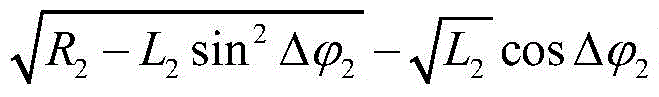
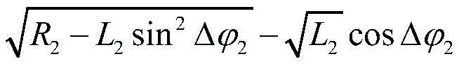
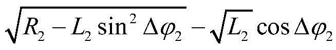
在本实施例中,对于二次谐波,可以利用各组的无记忆非线性传递函数的输入功率L2、输出功率R2和基波幅度A,来确定固有谐波和生成谐波的相位差


在以上的公式中,R2为对应二次谐波的所述无记忆非线性传递函数的输出功率,L2为对应二次谐波的所述无记忆非线性传递函数的输入功率,A为基波幅度,c2为对应二次谐波的非线性模型的系数,假设为常数。In the above formula, R 2 is the output power of the memoryless nonlinear transfer function corresponding to the second harmonic, L 2 is the input power of the memoryless nonlinear transfer function corresponding to the second harmonic, and A is The fundamental wave amplitude, c 2 is the coefficient of the nonlinear model corresponding to the second harmonic, and is assumed to be constant.
在本实施例中,确定相位差

在一个实施方式中,可以首先从0到2π的范围选择多个角度


在另一个实施方式中,可以首先从0到2π的范围选择多个角度


在本实施方式中,可以以预定步长选择上述角度,也可以随机选择,或者根据其他策略选择,本实施例并不以此作为限制。通过本实施方式,可以得到对应二次谐波的固有谐波和生成谐波之间的相位差
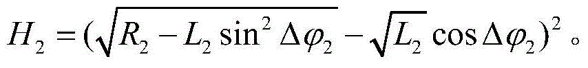
在一个实施方式中,可以通过以下公式分离出该待测系统生成的二次谐波的功率H2:In one embodiment, the power H 2 of the second harmonic generated by the system under test can be separated by the following formula:

该公式中各字母的含义如前所述,此处省略说明。The meaning of each letter in the formula is as described above, and the description is omitted here.
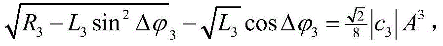
在本实施例中,对于三次谐波,方法与二次谐波类似,可以利用各组的无记忆非线性传递函数的输入功率L3、输出功率R3和基波幅度A,来确定固有谐波和生成谐波的相位差

在以上的公式中,R3为对应三次谐波的所述无记忆非线性传递函数的输出功率,L3为对应三次谐波的所述无记忆非线性传递函数的输入功率,A为基波幅度,c3为对应三次谐波的非线性模型的系数,假设为常数。In the above formula, R 3 is the output power of the memoryless nonlinear transfer function corresponding to the third harmonic, L 3 is the input power of the memoryless nonlinear transfer function corresponding to the third harmonic, and A is the fundamental wave Amplitude, c 3 is the coefficient of the nonlinear model corresponding to the third harmonic, assumed to be constant.
在本实施例中,与二次谐波的方法类似,在一个实施方式中,可以从0到2π的范围内选择多个角度


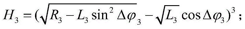
在本实施例中,得到了对应三次谐波的固有谐波和生成谐波之间的相位差

该公式中各字母的含义如前所述,此处省略说明。The meaning of each letter in the formula is as described above, and the description is omitted here.
以上通过二次谐波和三次谐波对本实施例的谐波分离做了说明,然而,本实施例的方法并不以此作为限制,在具体实施过程中,可以根据需要,利用相似的方法进行更高次谐波的谐波分离,得到分离后的由待测系统生成的谐波功率{H1,H2,H3,…}。由此,即可利用这些谐波功率来得到待测器件的非线性特性,并进行应对。The harmonic separation of this embodiment is described above through the second harmonic and the third harmonic. However, the method of this embodiment is not limited by this. In the specific implementation process, a similar method can be used as required. Harmonic separation of higher order harmonics to obtain the separated harmonic power {H 1 , H 2 , H 3 ,...} generated by the system under test. As a result, these harmonic powers can be used to obtain the nonlinear characteristics of the device under test and deal with them.
图5是测量待测系统的二次谐波的功率的性能验证示意图,如图5所示,应用本申请的方法,测得的谐波功率更准确。FIG. 5 is a schematic diagram of performance verification for measuring the power of the second harmonic of the system under test. As shown in FIG. 5 , by applying the method of the present application, the measured harmonic power is more accurate.
通过本实施例的方法,可以分离出由待测系统产生的谐波功率,以此用于非线性测量具有较高的准确度。With the method of this embodiment, the harmonic power generated by the system to be measured can be separated, so that it can be used for nonlinear measurement with high accuracy.
实施例2Example 2
本发明实施例还提供了一种非线性特性的确定方法,图6是该方法的一示意图,如图6所示,该方法包括:An embodiment of the present invention also provides a method for determining a nonlinear characteristic. FIG. 6 is a schematic diagram of the method. As shown in FIG. 6 , the method includes:
步骤601:利用待测系统的非线性模型的无记忆非线性传递函数的多组的输入功率、输出功率和基波幅度,确定固有谐波和生成谐波的相位差;Step 601: Determine the phase difference between the inherent harmonics and the generated harmonics by using the input power, output power and fundamental wave amplitude of multiple groups of memoryless nonlinear transfer functions of the nonlinear model of the system under test;
步骤602:利用所述相位差分离出所述待测系统生成的谐波的功率;Step 602: Use the phase difference to separate out the power of the harmonics generated by the system under test;
步骤603:利用分离出的所述待测系统生成的谐波的功率确定所述待测系统的非线性特性。Step 603: Determine the nonlinear characteristic of the system under test by using the power of the separated harmonics generated by the system under test.
在本实施例中,步骤601和步骤602的具体实施方式与实施例1的步骤301和步骤302相同,其内容被合并于此,此处不再赘述。In this embodiment, the specific implementations of
在本实施例中,利用分离出的给待测系统生成的谐波的功率,即可确定该待测系统的非线性特性。本实施例对具体的确定方法不作限制,任何可实施的方法都可以应用于本申请中。In this embodiment, the non-linear characteristic of the system under test can be determined by using the power of the separated harmonics generated for the system under test. This embodiment does not limit the specific determination method, and any practicable method can be applied in this application.
通过本实施例的方法,可以利用分离出的由待测系统产生的谐波功率,进行非线性特性的测量,具有较高的准确度。With the method of this embodiment, the separated harmonic power generated by the system to be measured can be used to measure the nonlinear characteristics, with high accuracy.
实施例2Example 2
本实施例提供了一种谐波失真分离装置,该装置配置于发射机或者接收机或者通信系统中,由于该装置解决问题的原理与实施例1的方法类似,因此其具体的实施可以参考实施例1的方法的实施,内容相同之处不再重复说明。This embodiment provides a device for separating harmonic distortion. The device is configured in a transmitter, a receiver, or a communication system. Since the principle of the device for solving problems is similar to that of the method in Embodiment 1, the specific implementation of the device may refer to the implementation of For the implementation of the method in Example 1, the same content will not be repeated.
图7是该装置的一示意图,如图7所示,该装置700包括确定单元701和分离单元702。FIG. 7 is a schematic diagram of the apparatus. As shown in FIG. 7 , the
在本实施例中,该确定单元701利用待测系统的非线性模型的无记忆非线性传递函数的多组的输入功率、输出功率和基波幅度,确定固有谐波和生成谐波的相位差。该分离单元702利用所述相位差分离出所述待测系统生成的谐波的功率。In this embodiment, the determining
在一个实施方式中,如图7所示,该确定单元701包括第一确定模块7011,该第一确定模块7011可以利用以下公式确定对应二次谐波的固有谐波和生成谐波之间的相位差

其中,R2为对应二次谐波的所述无记忆非线性传递函数的输出功率,L2为对应二次谐波的所述无记忆非线性传递函数的输入功率,A为基波幅度,c2为对应二次谐波的非线性模型的系数,假设为常数。Wherein, R 2 is the output power of the memoryless nonlinear transfer function corresponding to the second harmonic, L 2 is the input power of the memoryless nonlinear transfer function corresponding to the second harmonic, A is the fundamental wave amplitude, c 2 is a coefficient of the nonlinear model corresponding to the second harmonic, and is assumed to be a constant.
在该第一确定模块7011的一个实施方式中,如图8所示,该第一确定模块7011包括:第一选择模块801、第一线性拟合模块802、以及第二选择模块803。在该实施方式中,该第一选择模块801可以从0到2π的范围选择多个角度


图9是该实施方式的第一确定模块7011的硬件构成示意图,本实施例并不以此作为限制,该实施方式也可以通过软件实现。FIG. 9 is a schematic diagram of the hardware configuration of the
在该第一确定模块7011的另一个实施方式中,如图10所示,该第一确定模块7011包括:第三选择模块1001、第一除法模块1002、以及第四选择模块1003。在该实施方式中,该第三选择模块1001可以从0到2π的范围内选择多个角度

图11是该实施方式的第一确定模块7011的硬件构成示意图,本实施例并不以此作为限制,该实施方式也可以通过软件实现。FIG. 11 is a schematic diagram of the hardware configuration of the
在本实施方式中,如图7所示,该分离单元702包括:第一分离模块7021,其利用以下公式分离出所述待测系统生成的二次谐波的功率H2:In this embodiment, as shown in FIG. 7 , the

其中,各字母的含义如前所述。Among them, the meaning of each letter is as described above.
图12是该第一分离模块7021的硬件构成示意图,本实施例并不以此作为限制,该实施方式也可以通过软件实现。FIG. 12 is a schematic diagram of the hardware structure of the
在另一个实施方式中,如图7所示,该确定单元701还可以包括第二确定模块7012,该第二确定模块7012可以利用以下公式确定固有谐波和三次谐波之间的相位差
其中,R3为对应三次谐波的所述无记忆非线性传递函数的输出功率,L3为对应三次谐波的所述无记忆非线性传递函数的输入功率,A为基波幅度,c3为对应三次谐波的非线性模型的系数,假设为常数。Wherein, R3 is the output power of the memoryless nonlinear transfer function corresponding to the third harmonic, L3 is the input power of the memoryless nonlinear transfer function corresponding to the third harmonic, A is the fundamental wave amplitude, c3 are the coefficients of the nonlinear model corresponding to the third harmonic, assumed to be constant.
在该第二确定模块7012的一个实施方式中,与第一确定模块7011的第一个实施方式类似,如图13所示,该第二确定模块7012包括:第五选择模块1301、第二线性拟合模块1302、以及第六选择模块1303。该第五选择模块1301从0到2π的范围内选择多个角度


在该第二确定模块7012的另一个实施方式中,与第一确定模块7011的第二个实施方式类似,如图14所示,该第二确定模块7012包括:第七选择模块1401、第二除法模块1402、第八选择模块1403。该第七选择模块1401从0到2π的范围内选择多个角度Δφ3;本实施例对具体的选择方式不作限制;该第二除法模块1402利用每一个


在本实施方式中,如图7所示,该分离单元702还包括:第二分离模块7022,其利用以下公式分离出所述待测系统生成的三次谐波的功率H3:In this embodiment, as shown in FIG. 7 , the
其中,各字母的含义如前所述。Among them, the meaning of each letter is as described above.
在本实施方式中,关于该第二确定模块7012以及该第二分离模块7022的硬件实现方式,与前一实施方式类似,此处不再赘述。In this embodiment, the hardware implementation of the
通过本实施例的装置,可以分离出由待测系统产生的谐波功率,以此用于非线性测量具有较高的准确度。With the device of this embodiment, the harmonic power generated by the system to be measured can be separated, so that it can be used for nonlinear measurement with high accuracy.
实施例4Example 4
本实施例提供了一种非线性特性确定装置,该装置配置于发射机或者接收机或者通信系统中,由于该装置解决问题的原理与实施例2的方法类似,因此其具体的实施可以参考实施例2的方法的实施,内容相同之处不再重复说明。This embodiment provides an apparatus for determining nonlinear characteristics. The apparatus is configured in a transmitter, a receiver, or a communication system. Since the principle of the apparatus for solving problems is similar to that of the method in
图15是该装置的一示意图,如图15所示,该装置1500包括:第一确定单元1501、分离单元1502、和第二确定单元1503。FIG. 15 is a schematic diagram of the apparatus. As shown in FIG. 15 , the
在本实施例中,该第一确定单元1501利用待测系统的非线性模型的无记忆非线性传递函数的多组的输入功率、输出功率和基波幅度,确定固有谐波和生成谐波的相位差;该分离单元1502利用所述相位差分离出待测系统生成的谐波的功率;该第二确定单元1503利用分离出的所述待测系统生成的谐波的功率确定所述待测系统的非线性特性。In this embodiment, the first determining
在本实施例中,该第一确定单元1501和该分离单元1502可以分别通过实施例3的确定单元701和分离单元702来实现,其内容被合并于此,此处不再赘述。In this embodiment, the first determining
通过本实施例的装置,可以利用分离出的由待测系统产生的谐波功率,进行非线性特性的测量,具有较高的准确度。With the device in this embodiment, the separated harmonic power generated by the system to be measured can be used to measure the nonlinear characteristics with high accuracy.
实施例5Example 5
本实施例还提供了一种接收机,图16是该接收机的一示意图,如图16所示,该接收机1600包括实施例3所述的谐波失真分离装置或者包括实施例4所述的非线性特性的确定装置。由于在实施例3和实施例4中,已经对该谐波失真分离装置700和该非线性特性的确定装置1500做了详细说明,其内容被合并于此,此处不再赘述。This embodiment also provides a receiver, and FIG. 16 is a schematic diagram of the receiver. As shown in FIG. 16 , the
图17是本发明实施例的接收机的系统构成的一示意框图。如图17所示,接收机1700包括:FIG. 17 is a schematic block diagram of a system configuration of a receiver according to an embodiment of the present invention. As shown in Figure 17,
前端,其作用是将输入的光信号转换为两个偏振态上的基带信号,在本发明实施例中,该两个偏振态可包括H偏振态和V偏振态。The function of the front end is to convert the input optical signal into baseband signals in two polarization states. In this embodiment of the present invention, the two polarization states may include H polarization state and V polarization state.
如图17所示,该前端包括:本振激光器1710、光混频器(Optical 90deg hybrid)1701、光电检测器(O/E)1702、1704、1706和1708、数模转换器(ADC)1703、1705、1707和1709、色散补偿器1711、均衡器1712以及谐波失真分离装置或者非线性特性的确定装置1713,其中,谐波失真分离装置或者非线性特性的确定装置1713的结构与功能与实施例3或实施例4中的记载相同,此处不再赘述;本振激光器1710用于提供本地光源,光信号经光混频器(Optical 90deg hybrid)1701、光电检测器(O/E)1702和1704、数模转换器(ADC)1703和1705转换为一个偏振态上的基带信号;该光信号经光混频器(Optical 90deg hybrid)1701、光电检测器(O/E)1706和1708、数模转换器(ADC)1707和1709转换为另一个偏振态上的基带信号;其具体过程与现有技术类似,此处不再赘述。As shown in FIG. 17 , the front end includes: a local oscillator laser 1710 , an optical mixer (Optical 90deg hybrid) 1701 , photodetectors (O/E) 1702 , 1704 , 1706 and 1708 , and a digital-to-analog converter (ADC) 1703 , 1705 , 1707 and 1709 , the
此外,如果频差和相位噪声对OSNR的估计有影响,接收机1700中也可以包括频差补偿器和相位噪声补偿器(图中未示出)。In addition, if the frequency difference and phase noise have an influence on the estimation of OSNR, the
通过本实施例的接收机,可以分离出由待测系统产生的谐波功率,利用该谐波功率,进行非线性特性的测量,具有较高的准确度。With the receiver of this embodiment, the harmonic power generated by the system to be measured can be separated, and the nonlinear characteristic measurement can be performed by using the harmonic power with high accuracy.
实施例6Example 6
本实施例还提供一种发射机,图18是本实施例的发射机的组成示意图。如图18所示,该发射机1800包括实施例3所述的谐波失真分离装置或者包括实施例4所述的非线性特性的确定装置。由于在实施例3和实施例4中,已经对该谐波失真分离装置700和该非线性特性的确定装置1500做了详细说明,其内容被合并于此,此处不再赘述。This embodiment also provides a transmitter, and FIG. 18 is a schematic diagram of the composition of the transmitter in this embodiment. As shown in FIG. 18 , the
图19是本实施例的发射机的系统构成的一示意框图。如图19所示,发射机1900包括:信号生成器1901、信号设置单元1902、数模转换单元1903以及光调制器单元1904,其中:FIG. 19 is a schematic block diagram of the system configuration of the transmitter of this embodiment. As shown in FIG. 19, the
信号生成器1901根据发送数据生成数字信号;信号设置单元1902在生成的数字信号中设置导频信号;数模转换单元1903对该数字信号进行数模转换;光调制器单元1904以该数模转换单元1903转换后的信号作为调制信号对光进行调制。The
此外,该发射机还可以包括选择单元1905,光调制器单元1904根据选择单元1905选择的码字进行信号调制,使得不同偏振态上的导频信号的频率不同。In addition, the transmitter may further include a
并且,该发射机还可以包括谐波失真分离装置或者非线性特性的确定装置1906,用于对待测系统进行谐波失真分离或者进行非线性特性的估计。In addition, the transmitter may further include a harmonic distortion separation device or a nonlinear
通过本实施例的接收机,可以分离出由待测系统产生的谐波功率,利用该谐波功率,进行非线性特性的测量,具有较高的准确度。With the receiver of this embodiment, the harmonic power generated by the system to be measured can be separated, and the nonlinear characteristic measurement can be performed by using the harmonic power with high accuracy.
实施例7Example 7
本发明实施例还提供了一种通信系统,图20是本实施例的通信系统的结构示意图,如图20所示,通信系统2000包括发射机2001、传输链路2002以及接收机2003,其中,发射机2001的结构与功能与实施例6中的记载相同,接收机2003的结构与功能与实施例5中的记载相同,此处不再赘述。传输链路2002可具有现有的传输链路的结构与功能,本发明实施例不对传输链路的结构和功能进行限制。An embodiment of the present invention further provides a communication system. FIG. 20 is a schematic structural diagram of the communication system in this embodiment. As shown in FIG. 20, the
通过本发明实施例提供的通信系统,可以分离出由待测系统产生的谐波功率,利用该谐波功率,进行非线性特性的测量,具有较高的准确度。Through the communication system provided by the embodiment of the present invention, the harmonic power generated by the system to be measured can be separated, and the nonlinear characteristic measurement can be performed by using the harmonic power with high accuracy.
本发明实施例还提供一种计算机可读程序,其中当在发射机或接收机或通信系统中执行所述程序时,所述程序使得计算机在所述发射机或接收机或通信系统中执行实施例1或实施例2所述的方法。Embodiments of the present invention also provide a computer-readable program, wherein when the program is executed in a transmitter or receiver or a communication system, the program causes a computer to execute an implementation in the transmitter or receiver or communication system The method described in Example 1 or Example 2.
本发明实施例还提供一种存储有计算机可读程序的存储介质,其中所述计算机可读程序使得计算机在发射机或接收机或通信系统中执行实施例1或实施例2所述的方法。An embodiment of the present invention further provides a storage medium storing a computer-readable program, wherein the computer-readable program causes a computer to execute the method described in Embodiment 1 or
本发明以上的装置和方法可以由硬件实现,也可以由硬件结合软件实现。本发明涉及这样的计算机可读程序,当该程序被逻辑部件所执行时,能够使该逻辑部件实现上文所述的装置或构成部件,或使该逻辑部件实现上文所述的各种方法或步骤。本发明还涉及用于存储以上程序的存储介质,如硬盘、磁盘、光盘、DVD、flash存储器等。The above apparatus and method of the present invention may be implemented by hardware, or may be implemented by hardware combined with software. The present invention relates to a computer-readable program which, when executed by logic components, enables the logic components to implement the above-described apparatus or constituent components, or causes the logic components to implement the above-described various methods or steps. The present invention also relates to a storage medium for storing the above program, such as a hard disk, a magnetic disk, an optical disk, a DVD, a flash memory, and the like.
以上结合具体的实施方式对本发明进行了描述,但本领域技术人员应该清楚,这些描述都是示例性的,并不是对本发明保护范围的限制。本领域技术人员可以根据本发明的精神和原理对本发明做出各种变型和修改,这些变型和修改也在本发明的范围内。The present invention has been described above with reference to the specific embodiments, but those skilled in the art should understand that these descriptions are all exemplary and do not limit the protection scope of the present invention. Various variations and modifications of the present invention can be made by those skilled in the art in accordance with the spirit and principles of the present invention, and these variations and modifications are also within the scope of the present invention.
关于包括以上实施例的实施方式,还公开下述的附记:Regarding the implementations including the above embodiments, the following additional notes are also disclosed:
附记1、一种谐波失真分离装置,配置于发射机或者接收机或者通信系统中,其中,该装置包括:Supplementary Note 1. A harmonic distortion separation device, configured in a transmitter or a receiver or a communication system, wherein the device includes:
确定单元,其利用待测系统的非线性模型的无记忆非线性传递函数的多组的输入功率、输出功率和基波幅度,确定固有谐波和生成谐波的相位差;a determination unit, which determines the phase difference between the inherent harmonics and the generated harmonics by using the multiple sets of input power, output power and fundamental wave amplitude of the memoryless nonlinear transfer function of the nonlinear model of the system under test;
分离单元,其利用所述相位差分离出所述待测系统生成的谐波的功率。A separation unit, which uses the phase difference to separate the power of the harmonics generated by the system under test.
附记2、根据附记1所述装置,其中,所述确定单元包括:
第一确定模块,其利用以下公式确定对应二次谐波的固有谐波和生成谐波之间的相位差

其中,R2为对应二次谐波的所述无记忆非线性传递函数的输出功率,L2为对应二次谐波的所述无记忆非线性传递函数的输入功率,A为基波幅度,c2为对应二次谐波的非线性模型的系数,假设为常数。Wherein, R 2 is the output power of the memoryless nonlinear transfer function corresponding to the second harmonic, L 2 is the input power of the memoryless nonlinear transfer function corresponding to the second harmonic, A is the fundamental wave amplitude, c 2 is a coefficient of the nonlinear model corresponding to the second harmonic, and is assumed to be a constant.
附记3、根据附记2所述的装置,其中,所述第一确定模块包括:Supplement 3. The device according to
第一选择模块,其从0到2π的范围选择多个角度
第一线性拟合模块,其利用每一个

第二选择模块,其选择使拟合相关系数最大的
附记4、根据附记2所述的装置,其中,所述第一确定模块包括:
第三选择模块,其从0到2π的范围内选择多个角度
第一除法模块,其利用每一个


第四选择模块,其选择使各组的商的方差最小的
附记5、根据附记2所述的装置,其中,所述分离单元包括:Supplement 5. The device according to
第一分离模块,其利用以下公式分离出所述待测系统生成的二次谐波的功率H2:The first separation module, which uses the following formula to separate the power H 2 of the second harmonic generated by the system under test:

附记6、根据附记1所述的装置,其中,所述确定单元包括:
第二确定模块,其利用以下公式确定对应三次谐波的固有谐波和生成谐波之间的相位差

其中,R3为对应三次谐波的所述无记忆非线性传递函数的输出功率,L3为对应三次谐波的所述无记忆非线性传递函数的输入功率,A为基波幅度,c3为对应三次谐波的非线性模型的系数,假设为常数。Wherein, R3 is the output power of the memoryless nonlinear transfer function corresponding to the third harmonic, L3 is the input power of the memoryless nonlinear transfer function corresponding to the third harmonic, A is the fundamental wave amplitude, c3 are the coefficients of the nonlinear model corresponding to the third harmonic, assumed to be constant.
附记7、根据附记6所述的装置,其中,所述第二确定模块包括:Supplement 7. The device according to
第五选择模块,其从0到2π的范围内选择多个角度
第二线性拟合模块,其利用每一个


第六选择模块,其选择使拟合相关系数最大的
附记8、根据附记6所述的装置,其中,所述第二确定模块包括:
第七选择模块,其从0到2π的范围内选择多个角度
第二除法模块,其利用每一个


第八选择模块,其选择使各组的商的方差最小的
附记9、根据附记6所述的装置,其中,所述分离单元包括:Supplement 9. The device according to
第二分离模块,其利用以下公式分离出所述待测系统生成的三次谐波的功率H3:The second separation module, which uses the following formula to separate the power H 3 of the third harmonic generated by the system under test:
附记10、一种非线性特性确定装置,配置于发射机或者接收机或者通信系统中,其中,该装置包括:
第一确定单元,其利用待测系统的非线性模型的无记忆非线性传递函数的多组的输入功率、输出功率和基波幅度,确定固有谐波和生成谐波的相位差;a first determining unit, which utilizes multiple sets of input power, output power and fundamental wave amplitude of the memoryless nonlinear transfer function of the nonlinear model of the system under test to determine the phase difference between the inherent harmonic and the generated harmonic;
分离单元,其利用所述相位差分离出待测系统生成的谐波的功率;a separation unit, which uses the phase difference to separate the power of the harmonics generated by the system under test;
第二确定单元,其利用分离出的所述待测系统生成的谐波的功率确定所述待测系统的非线性特性。The second determination unit determines the nonlinear characteristic of the system under test by using the power of the separated harmonics generated by the system under test.
附记11、一种谐波失真分离方法,其中,该方法包括:Appendix 11. A harmonic distortion separation method, wherein the method includes:
利用待测系统的非线性模型的无记忆非线性传递函数的多组的输入功率、输出功率和基波幅度,确定固有谐波和生成谐波的相位差;Using the input power, output power and fundamental wave amplitude of multiple groups of the memoryless nonlinear transfer function of the nonlinear model of the system under test, determine the phase difference between the inherent harmonic and the generated harmonic;
利用所述相位差分离出所述待测系统生成的谐波的功率。The power of the harmonics generated by the system under test is separated by using the phase difference.
附记12、根据附记11所述方法,其中,所述确定固有谐波和生成谐波的相位差,包括:Supplement 12. The method according to Supplement 11, wherein the determining the phase difference between the natural harmonic and the generated harmonic includes:
利用以下公式确定对应二次谐波的固有谐波和生成谐波之间的相位差

其中,R2为对应二次谐波的所述无记忆非线性传递函数的输出功率,L2为对应二次谐波的所述无记忆非线性传递函数的输入功率,A为基波幅度,c2为对应二次谐波的非线性模型的系数,假设为常数。Wherein, R 2 is the output power of the memoryless nonlinear transfer function corresponding to the second harmonic, L 2 is the input power of the memoryless nonlinear transfer function corresponding to the second harmonic, A is the fundamental wave amplitude, c 2 is a coefficient of the nonlinear model corresponding to the second harmonic, and is assumed to be a constant.
附记13、根据附记12所述的方法,其中,所述确定对应二次谐波的固有谐波和生成谐波之间的相位差
从0到2π的范围选择多个角度
利用每一个

选择使拟合相关系数最大的
附记14、根据附记12所述的方法,其中,所述确定对应二次谐波的固有谐波和生成谐波之间的相位差
从0到2π的范围内选择多个角度
利用每一个


选择使各组的商的方差最小的
附记15、根据附记12所述的方法,其中,所述利用所述相位差分离出所述待测系统生成的谐波的功率,包括:
利用以下公式分离出所述待测系统生成的二次谐波的功率H2:The power H 2 of the second harmonic generated by the system under test is separated by the following formula:
附记16、根据附记11所述的方法,其中,所述确定固有谐波和生成谐波的相位差,包括:Supplement 16. The method according to Supplement 11, wherein the determining the phase difference between the natural harmonic and the generated harmonic includes:
利用以下公式确定对应三次谐波的固有谐波和生成谐波之间的相位差

其中,R3为对应三次谐波的所述无记忆非线性传递函数的输出功率,L3为对应三次谐波的所述无记忆非线性传递函数的输入功率,A为基波幅度,c3为对应三次谐波的非线性模型的系数,假设为常数。Wherein, R3 is the output power of the memoryless nonlinear transfer function corresponding to the third harmonic, L3 is the input power of the memoryless nonlinear transfer function corresponding to the third harmonic, A is the fundamental wave amplitude, c3 are the coefficients of the nonlinear model corresponding to the third harmonic, assumed to be constant.
附记17、根据附记16所述的方法,其中,所述确定对应三次谐波的固有谐波和生成谐波之间的相位差
从0到2π的范围内选择多个角度
利用每一个


选择使拟合相关系数最大的
附记18、根据附记16所述的方法,其中,所述确定对应三次谐波的固有谐波和生成谐波之间的相位差
从0到2π的范围内选择多个角度
利用每一个

选择使各组的商的方差最小的Δφ2作为对应三次谐波的所述相位差。Δφ 2 that minimizes the variance of the quotients of each group is selected as the phase difference corresponding to the third harmonic.
附记19、根据附记16所述的方法,其中,所述利用所述相位差分离出所述待测系统生成的谐波的功率,包括:Supplementary Note 19. The method according to Supplementary Note 16, wherein the step of using the phase difference to separate the power of the harmonics generated by the system under test includes:
第二分离模块,其利用以下公式分离出所述待测系统生成的三次谐波的功率H3:The second separation module, which uses the following formula to separate the power H 3 of the third harmonic generated by the system under test:

Claims (10)


Priority Applications (3)
| Application Number | Priority Date | Filing Date | Title |
|---|---|---|---|
| CN201610083856.9A CN107046445B (en) | 2016-02-06 | 2016-02-06 | Harmonic distortion separation method, nonlinear characteristic determination method, device and system |
| JP2017017368A JP6926496B2 (en) | 2016-02-06 | 2017-02-02 | Harmonic distortion separation method, nonlinear characteristic determination method, equipment and system |
| US15/425,392 US10739388B2 (en) | 2016-02-06 | 2017-02-06 | Harmonic distortion separation method, nonlinear character determination method and apparatus and system |
Applications Claiming Priority (1)
| Application Number | Priority Date | Filing Date | Title |
|---|---|---|---|
| CN201610083856.9A CN107046445B (en) | 2016-02-06 | 2016-02-06 | Harmonic distortion separation method, nonlinear characteristic determination method, device and system |
Publications (2)
| Publication Number | Publication Date |
|---|---|
| CN107046445A CN107046445A (en) | 2017-08-15 |
| CN107046445B true CN107046445B (en) | 2020-07-28 |
Family
ID=59496312
Family Applications (1)
| Application Number | Title | Priority Date | Filing Date |
|---|---|---|---|
| CN201610083856.9A Expired - Fee Related CN107046445B (en) | 2016-02-06 | 2016-02-06 | Harmonic distortion separation method, nonlinear characteristic determination method, device and system |
Country Status (3)
| Country | Link |
|---|---|
| US (1) | US10739388B2 (en) |
| JP (1) | JP6926496B2 (en) |
| CN (1) | CN107046445B (en) |
Families Citing this family (4)
| Publication number | Priority date | Publication date | Assignee | Title |
|---|---|---|---|---|
| CN106161125B (en) * | 2015-03-31 | 2019-05-17 | 富士通株式会社 | Apparatus and method for estimating nonlinear characteristics |
| CN106878206B (en) * | 2015-12-11 | 2020-07-28 | 富士通株式会社 | Method and device for measuring filtering characteristic, pre-equalizer and communication equipment |
| CN108540242B (en) * | 2018-01-05 | 2021-06-25 | 中国传媒大学广州研究院 | Method and device for measuring harmonic distortion index of broadcast transmitter |
| CN111257635B (en) * | 2020-01-17 | 2021-04-30 | 电子科技大学 | A Harmonic Detection Device for Multi-Port Nonlinear Devices |
Citations (1)
| Publication number | Priority date | Publication date | Assignee | Title |
|---|---|---|---|---|
| CN104122443A (en) * | 2014-08-04 | 2014-10-29 | 国家电网公司 | Adjacent harmonic and inter-harmonic separation and measurement method under IEC (international electrotechnical commission) framework |
Family Cites Families (7)
| Publication number | Priority date | Publication date | Assignee | Title |
|---|---|---|---|---|
| JPH0637551A (en) * | 1992-07-17 | 1994-02-10 | Fujitsu Ltd | Distortion compensation circuit |
| US6246286B1 (en) * | 1999-10-26 | 2001-06-12 | Telefonaktiebolaget Lm Ericsson | Adaptive linearization of power amplifiers |
| EP1573993B1 (en) * | 2002-10-31 | 2010-01-13 | ZTE Corporation | A method and system for broadband predistortion linearizaion |
| US7561857B2 (en) * | 2006-08-30 | 2009-07-14 | Infineon Technologies Ag | Model network of a nonlinear circuitry |
| US20080158026A1 (en) * | 2006-12-29 | 2008-07-03 | O'brien David | Compensating for harmonic distortion in an instrument channel |
| US8400338B2 (en) * | 2006-12-29 | 2013-03-19 | Teradyne, Inc. | Compensating for harmonic distortion in an instrument channel |
| CN103901273B (en) * | 2012-12-28 | 2017-12-22 | 白晓民 | Power grid harmonic wave detection method and Harmonic Measuring Equipment |
-
2016
- 2016-02-06 CN CN201610083856.9A patent/CN107046445B/en not_active Expired - Fee Related
-
2017
- 2017-02-02 JP JP2017017368A patent/JP6926496B2/en not_active Expired - Fee Related
- 2017-02-06 US US15/425,392 patent/US10739388B2/en not_active Expired - Fee Related
Patent Citations (1)
| Publication number | Priority date | Publication date | Assignee | Title |
|---|---|---|---|---|
| CN104122443A (en) * | 2014-08-04 | 2014-10-29 | 国家电网公司 | Adjacent harmonic and inter-harmonic separation and measurement method under IEC (international electrotechnical commission) framework |
Also Published As
| Publication number | Publication date |
|---|---|
| CN107046445A (en) | 2017-08-15 |
| US10739388B2 (en) | 2020-08-11 |
| JP2017139762A (en) | 2017-08-10 |
| US20170227585A1 (en) | 2017-08-10 |
| JP6926496B2 (en) | 2021-08-25 |
Similar Documents
| Publication | Publication Date | Title |
|---|---|---|
| CN112448760B (en) | Method and device for obtaining transmitter test parameters and storage medium | |
| CN107046445B (en) | Harmonic distortion separation method, nonlinear characteristic determination method, device and system | |
| EP2393224B1 (en) | Method and apparatus for synthesizing and correcting phase distortions in ultra-wide bandwidth optical waveforms | |
| KR102458095B1 (en) | Phase correction method and device | |
| CN103713194A (en) | Phase detection method for clock recovery and apparatuses | |
| WO2012117531A1 (en) | Clock generator and system including same | |
| CN107210935A (en) | Method and system for removing pilot tone from optical signal | |
| CN103728553A (en) | Method for verifying electric energy measuring chip | |
| CN104780131A (en) | Chromatic dispersion measurement method and device and digital coherent receiver | |
| CN109557365B (en) | Grid voltage frequency and phase angle detection method and system, single-phase grid detection system | |
| CN102095915A (en) | Voltage signal detecting device using multiple synchronous reference coordinate system transformation | |
| CN104734713A (en) | Method and converter device for converting an analog input signal into a digital output signal | |
| CN107276591A (en) | The mismatch error method of estimation and system of a kind of parallel sampling system | |
| CN102497236A (en) | Method for utilizing network analyzer to localize and track dynamic signal and method thereof | |
| CN107819519B (en) | Measuring device for residual DC component | |
| CN111147148B (en) | Signal sending method, device, terminal and medium | |
| CN105277780A (en) | Voltage zero-crossing point obtaining method and device | |
| CN109581094B (en) | Estimation device, method and system for phase shift characteristic of phase shifter | |
| CN105429634A (en) | Single-phase phase-locked control method and device | |
| CN117074745A (en) | A DC transient voltage generation method, device, system and storage medium for flexible DC control protection testing | |
| CN111416659B (en) | Optical signal time-domain waveform measurement method, device, electronic equipment and medium | |
| CN107219750A (en) | Improve the delay line real-time noise modification method of atomic clock stability | |
| CN117233503B (en) | A method and related device for testing inertia and damping of grid-type converter | |
| CN111565128B (en) | A kind of synchronous equivalent bandwidth testing method and device | |
| US20200213733A1 (en) | Audio Filter With Through-Zero Linearly Variable Resonant Frequency |
Legal Events
| Date | Code | Title | Description |
|---|---|---|---|
| PB01 | Publication | ||
| PB01 | Publication | ||
| SE01 | Entry into force of request for substantive examination | ||
| SE01 | Entry into force of request for substantive examination | ||
| GR01 | Patent grant | ||
| GR01 | Patent grant | ||
| CF01 | Termination of patent right due to non-payment of annual fee |
Granted publication date: 20200728 |
|
| CF01 | Termination of patent right due to non-payment of annual fee |