CN107036220B - humidifier - Google Patents
humidifier Download PDFInfo
- Publication number
- CN107036220B CN107036220B CN201710100650.7A CN201710100650A CN107036220B CN 107036220 B CN107036220 B CN 107036220B CN 201710100650 A CN201710100650 A CN 201710100650A CN 107036220 B CN107036220 B CN 107036220B
- Authority
- CN
- China
- Prior art keywords
- water
- air
- reservoir
- transducer
- nozzle
- Prior art date
- Legal status (The legal status is an assumption and is not a legal conclusion. Google has not performed a legal analysis and makes no representation as to the accuracy of the status listed.)
- Active
Links
Images


Classifications
-
- C—CHEMISTRY; METALLURGY
- C02—TREATMENT OF WATER, WASTE WATER, SEWAGE, OR SLUDGE
- C02F—TREATMENT OF WATER, WASTE WATER, SEWAGE, OR SLUDGE
- C02F1/00—Treatment of water, waste water, or sewage
- C02F1/30—Treatment of water, waste water, or sewage by irradiation
- C02F1/32—Treatment of water, waste water, or sewage by irradiation with ultraviolet light
-
- B—PERFORMING OPERATIONS; TRANSPORTING
- B01—PHYSICAL OR CHEMICAL PROCESSES OR APPARATUS IN GENERAL
- B01J—CHEMICAL OR PHYSICAL PROCESSES, e.g. CATALYSIS OR COLLOID CHEMISTRY; THEIR RELEVANT APPARATUS
- B01J19/00—Chemical, physical or physico-chemical processes in general; Their relevant apparatus
- B01J19/08—Processes employing the direct application of electric or wave energy, or particle radiation; Apparatus therefor
- B01J19/10—Processes employing the direct application of electric or wave energy, or particle radiation; Apparatus therefor employing sonic or ultrasonic vibrations
-
- F—MECHANICAL ENGINEERING; LIGHTING; HEATING; WEAPONS; BLASTING
- F04—POSITIVE - DISPLACEMENT MACHINES FOR LIQUIDS; PUMPS FOR LIQUIDS OR ELASTIC FLUIDS
- F04D—NON-POSITIVE-DISPLACEMENT PUMPS
- F04D25/00—Pumping installations or systems
- F04D25/02—Units comprising pumps and their driving means
- F04D25/08—Units comprising pumps and their driving means the working fluid being air, e.g. for ventilation
-
- F—MECHANICAL ENGINEERING; LIGHTING; HEATING; WEAPONS; BLASTING
- F04—POSITIVE - DISPLACEMENT MACHINES FOR LIQUIDS; PUMPS FOR LIQUIDS OR ELASTIC FLUIDS
- F04D—NON-POSITIVE-DISPLACEMENT PUMPS
- F04D29/00—Details, component parts, or accessories
- F04D29/40—Casings; Connections of working fluid
- F04D29/42—Casings; Connections of working fluid for radial or helico-centrifugal pumps
- F04D29/44—Fluid-guiding means, e.g. diffusers
- F04D29/441—Fluid-guiding means, e.g. diffusers especially adapted for elastic fluid pumps
-
- F—MECHANICAL ENGINEERING; LIGHTING; HEATING; WEAPONS; BLASTING
- F04—POSITIVE - DISPLACEMENT MACHINES FOR LIQUIDS; PUMPS FOR LIQUIDS OR ELASTIC FLUIDS
- F04D—NON-POSITIVE-DISPLACEMENT PUMPS
- F04D29/00—Details, component parts, or accessories
- F04D29/40—Casings; Connections of working fluid
- F04D29/52—Casings; Connections of working fluid for axial pumps
- F04D29/54—Fluid-guiding means, e.g. diffusers
- F04D29/541—Specially adapted for elastic fluid pumps
- F04D29/545—Ducts
-
- F—MECHANICAL ENGINEERING; LIGHTING; HEATING; WEAPONS; BLASTING
- F04—POSITIVE - DISPLACEMENT MACHINES FOR LIQUIDS; PUMPS FOR LIQUIDS OR ELASTIC FLUIDS
- F04F—PUMPING OF FLUID BY DIRECT CONTACT OF ANOTHER FLUID OR BY USING INERTIA OF FLUID TO BE PUMPED; SIPHONS
- F04F5/00—Jet pumps, i.e. devices in which flow is induced by pressure drop caused by velocity of another fluid flow
- F04F5/14—Jet pumps, i.e. devices in which flow is induced by pressure drop caused by velocity of another fluid flow the inducing fluid being elastic fluid
- F04F5/16—Jet pumps, i.e. devices in which flow is induced by pressure drop caused by velocity of another fluid flow the inducing fluid being elastic fluid displacing elastic fluids
- F04F5/20—Jet pumps, i.e. devices in which flow is induced by pressure drop caused by velocity of another fluid flow the inducing fluid being elastic fluid displacing elastic fluids for evacuating
-
- F—MECHANICAL ENGINEERING; LIGHTING; HEATING; WEAPONS; BLASTING
- F04—POSITIVE - DISPLACEMENT MACHINES FOR LIQUIDS; PUMPS FOR LIQUIDS OR ELASTIC FLUIDS
- F04F—PUMPING OF FLUID BY DIRECT CONTACT OF ANOTHER FLUID OR BY USING INERTIA OF FLUID TO BE PUMPED; SIPHONS
- F04F5/00—Jet pumps, i.e. devices in which flow is induced by pressure drop caused by velocity of another fluid flow
- F04F5/44—Component parts, details, or accessories not provided for in, or of interest apart from, groups F04F5/02 - F04F5/42
- F04F5/46—Arrangements of nozzles
-
- F—MECHANICAL ENGINEERING; LIGHTING; HEATING; WEAPONS; BLASTING
- F24—HEATING; RANGES; VENTILATING
- F24F—AIR-CONDITIONING; AIR-HUMIDIFICATION; VENTILATION; USE OF AIR CURRENTS FOR SCREENING
- F24F11/00—Control or safety arrangements
- F24F11/30—Control or safety arrangements for purposes related to the operation of the system, e.g. for safety or monitoring
-
- F—MECHANICAL ENGINEERING; LIGHTING; HEATING; WEAPONS; BLASTING
- F24—HEATING; RANGES; VENTILATING
- F24F—AIR-CONDITIONING; AIR-HUMIDIFICATION; VENTILATION; USE OF AIR CURRENTS FOR SCREENING
- F24F11/00—Control or safety arrangements
- F24F11/62—Control or safety arrangements characterised by the type of control or by internal processing, e.g. using fuzzy logic, adaptive control or estimation of values
- F24F11/63—Electronic processing
- F24F11/64—Electronic processing using pre-stored data
-
- F—MECHANICAL ENGINEERING; LIGHTING; HEATING; WEAPONS; BLASTING
- F24—HEATING; RANGES; VENTILATING
- F24F—AIR-CONDITIONING; AIR-HUMIDIFICATION; VENTILATION; USE OF AIR CURRENTS FOR SCREENING
- F24F11/00—Control or safety arrangements
- F24F11/70—Control systems characterised by their outputs; Constructional details thereof
-
- F—MECHANICAL ENGINEERING; LIGHTING; HEATING; WEAPONS; BLASTING
- F24—HEATING; RANGES; VENTILATING
- F24F—AIR-CONDITIONING; AIR-HUMIDIFICATION; VENTILATION; USE OF AIR CURRENTS FOR SCREENING
- F24F3/00—Air-conditioning systems in which conditioned primary air is supplied from one or more central stations to distributing units in the rooms or spaces where it may receive secondary treatment; Apparatus specially designed for such systems
- F24F3/12—Air-conditioning systems in which conditioned primary air is supplied from one or more central stations to distributing units in the rooms or spaces where it may receive secondary treatment; Apparatus specially designed for such systems characterised by the treatment of the air otherwise than by heating and cooling
- F24F3/14—Air-conditioning systems in which conditioned primary air is supplied from one or more central stations to distributing units in the rooms or spaces where it may receive secondary treatment; Apparatus specially designed for such systems characterised by the treatment of the air otherwise than by heating and cooling by humidification; by dehumidification
-
- F—MECHANICAL ENGINEERING; LIGHTING; HEATING; WEAPONS; BLASTING
- F24—HEATING; RANGES; VENTILATING
- F24F—AIR-CONDITIONING; AIR-HUMIDIFICATION; VENTILATION; USE OF AIR CURRENTS FOR SCREENING
- F24F6/00—Air-humidification, e.g. cooling by humidification
- F24F6/12—Air-humidification, e.g. cooling by humidification by forming water dispersions in the air
- F24F6/14—Air-humidification, e.g. cooling by humidification by forming water dispersions in the air using nozzles
-
- F—MECHANICAL ENGINEERING; LIGHTING; HEATING; WEAPONS; BLASTING
- F24—HEATING; RANGES; VENTILATING
- F24F—AIR-CONDITIONING; AIR-HUMIDIFICATION; VENTILATION; USE OF AIR CURRENTS FOR SCREENING
- F24F8/00—Treatment, e.g. purification, of air supplied to human living or working spaces otherwise than by heating, cooling, humidifying or drying
- F24F8/20—Treatment, e.g. purification, of air supplied to human living or working spaces otherwise than by heating, cooling, humidifying or drying by sterilisation
- F24F8/22—Treatment, e.g. purification, of air supplied to human living or working spaces otherwise than by heating, cooling, humidifying or drying by sterilisation using UV light
-
- F—MECHANICAL ENGINEERING; LIGHTING; HEATING; WEAPONS; BLASTING
- F24—HEATING; RANGES; VENTILATING
- F24F—AIR-CONDITIONING; AIR-HUMIDIFICATION; VENTILATION; USE OF AIR CURRENTS FOR SCREENING
- F24F8/00—Treatment, e.g. purification, of air supplied to human living or working spaces otherwise than by heating, cooling, humidifying or drying
- F24F8/80—Self-contained air purifiers
-
- B—PERFORMING OPERATIONS; TRANSPORTING
- B01—PHYSICAL OR CHEMICAL PROCESSES OR APPARATUS IN GENERAL
- B01F—MIXING, e.g. DISSOLVING, EMULSIFYING OR DISPERSING
- B01F25/00—Flow mixers; Mixers for falling materials, e.g. solid particles
-
- F—MECHANICAL ENGINEERING; LIGHTING; HEATING; WEAPONS; BLASTING
- F24—HEATING; RANGES; VENTILATING
- F24F—AIR-CONDITIONING; AIR-HUMIDIFICATION; VENTILATION; USE OF AIR CURRENTS FOR SCREENING
- F24F6/00—Air-humidification, e.g. cooling by humidification
- F24F2006/006—Air-humidification, e.g. cooling by humidification with water treatment
-
- F—MECHANICAL ENGINEERING; LIGHTING; HEATING; WEAPONS; BLASTING
- F24—HEATING; RANGES; VENTILATING
- F24F—AIR-CONDITIONING; AIR-HUMIDIFICATION; VENTILATION; USE OF AIR CURRENTS FOR SCREENING
- F24F6/00—Air-humidification, e.g. cooling by humidification
- F24F2006/008—Air-humidifier with water reservoir
-
- F—MECHANICAL ENGINEERING; LIGHTING; HEATING; WEAPONS; BLASTING
- F24—HEATING; RANGES; VENTILATING
- F24F—AIR-CONDITIONING; AIR-HUMIDIFICATION; VENTILATION; USE OF AIR CURRENTS FOR SCREENING
- F24F6/00—Air-humidification, e.g. cooling by humidification
- F24F6/12—Air-humidification, e.g. cooling by humidification by forming water dispersions in the air
- F24F6/14—Air-humidification, e.g. cooling by humidification by forming water dispersions in the air using nozzles
- F24F2006/143—Air-humidification, e.g. cooling by humidification by forming water dispersions in the air using nozzles using pressurised air for spraying
-
- Y—GENERAL TAGGING OF NEW TECHNOLOGICAL DEVELOPMENTS; GENERAL TAGGING OF CROSS-SECTIONAL TECHNOLOGIES SPANNING OVER SEVERAL SECTIONS OF THE IPC; TECHNICAL SUBJECTS COVERED BY FORMER USPC CROSS-REFERENCE ART COLLECTIONS [XRACs] AND DIGESTS
- Y02—TECHNOLOGIES OR APPLICATIONS FOR MITIGATION OR ADAPTATION AGAINST CLIMATE CHANGE
- Y02B—CLIMATE CHANGE MITIGATION TECHNOLOGIES RELATED TO BUILDINGS, e.g. HOUSING, HOUSE APPLIANCES OR RELATED END-USER APPLICATIONS
- Y02B30/00—Energy efficient heating, ventilation or air conditioning [HVAC]
- Y02B30/70—Efficient control or regulation technologies, e.g. for control of refrigerant flow, motor or heating
Landscapes
- Engineering & Computer Science (AREA)
- Mechanical Engineering (AREA)
- General Engineering & Computer Science (AREA)
- Chemical & Material Sciences (AREA)
- Combustion & Propulsion (AREA)
- Physics & Mathematics (AREA)
- Fluid Mechanics (AREA)
- Dispersion Chemistry (AREA)
- Organic Chemistry (AREA)
- Health & Medical Sciences (AREA)
- Toxicology (AREA)
- Signal Processing (AREA)
- Life Sciences & Earth Sciences (AREA)
- Water Supply & Treatment (AREA)
- Environmental & Geological Engineering (AREA)
- Fuzzy Systems (AREA)
- Mathematical Physics (AREA)
- Hydrology & Water Resources (AREA)
- General Health & Medical Sciences (AREA)
- Chemical Kinetics & Catalysis (AREA)
- Air Humidification (AREA)
- Physical Water Treatments (AREA)
- Nozzles (AREA)
Abstract
一种加湿装置包括基座和安装在基座上的喷嘴。喷嘴具有用于从第一空气入口输送空气到第一空气出口的第一内部通道、和用于从第二空气入口输送空气到第二空气出口的第二内部通道。喷嘴定义孔眼,来自加湿装置外部的空气由从空气出口发射的空气抽吸穿过孔眼。本体包括马达和叶轮单元,用于产生穿过第一内部通道的第一空气流和穿过第二内部通道和水存储器的第二空气流。第一空气通道输送第一空气流到第一空气入口且第二空气通道在存储器中的水的上方输送第二空气流到第二空气入口。存储在存储器中的水在第二空气流从存储器上方经过时被搅动。紫外线辐射发生器照射被搅动的水一时间段,然后存储在存储器中的水被雾化以增加第二空气流的湿度。
A humidification device includes a base and a nozzle mounted on the base. The nozzle has a first inner passage for delivering air from the first air inlet to the first air outlet, and a second inner passage for delivering air from the second air inlet to the second air outlet. The nozzle defines an orifice through which air from outside the humidification device is drawn by the air emitted from the air outlet. The body includes a motor and impeller unit for generating a first air flow through the first inner channel and a second air flow through the second inner channel and the water reservoir. The first air channel delivers the first air flow to the first air inlet and the second air channel delivers the second air flow to the second air inlet above the water in the reservoir. The water stored in the reservoir is agitated as the second air flow passes over the reservoir. The ultraviolet radiation generator illuminates the agitated water for a period of time, and then the water stored in the reservoir is atomized to increase the humidity of the second air stream.
Description
本申请是申请日为2013年03月06日、申请号为201310071220.9、发明名称为“加湿装置”的发明专利申请的分案申请。This application is a divisional application of an invention patent application with an application date of March 6, 2013, an application number of 201310071220.9, and an invention name of "humidification device".
技术领域technical field
本发明涉及一种加湿装置,且涉及一种产生潮湿空气流的方法。在优选实施例中,本发明提供了一种用于产生湿空气流和用于在室内环境(如房间,办公室或诸如此类)发散湿空气的空气流的加湿装置。The present invention relates to a humidification device and to a method for generating a stream of moist air. In a preferred embodiment, the present invention provides a humidification device for generating and dissipating a flow of moist air in an indoor environment such as a room, office or the like.
背景技术Background technique
家用加湿装置通常是便携式器具的形式,该器具具有包括储存大量水的水箱的壳体和用于产生空气流动穿过壳体的空气导管的风扇。储存的水通常在重力作用下被输送到用于从接收到的水产生水滴的雾化设备。这个设备可以是加热器或高频率振动设备的形式,如换能器。该水滴进入穿过空气导管的空气流导致薄雾发射进入环境。该器具可包括用于检测在环境中的空气的相对湿度的传感器。该传感器输出检测到的相对湿度的指示信号到驱动电路,该驱动电路控制换能器以保持环境中的空气的相对湿度大约在期望水平。典型地,当检测到的相对湿度高于期望水平约5%时停止换能器的促动,当检测到的相对湿度低于期望水平约5%时重新启动换能器。Home humidification devices are usually in the form of portable appliances having a housing including a water tank storing a large amount of water and a fan for creating air ducts that flow air through the housing. The stored water is usually conveyed by gravity to an atomizing device for generating water droplets from the received water. This device can be in the form of a heater or a high frequency vibrating device such as a transducer. The entry of this droplet into the air flow through the air duct causes the mist to be emitted into the environment. The appliance may include a sensor for detecting the relative humidity of the air in the environment. The sensor outputs an indication of the detected relative humidity to a drive circuit that controls the transducer to maintain the relative humidity of the air in the environment at approximately a desired level. Typically, actuation of the transducer is stopped when the detected relative humidity is about 5% above the desired level, and the transducer is restarted when the detected relative humidity is about 5% below the desired level.
已知的是提供紫外线(UV)灯或其它UV辐射发生器对被运输到雾化设备的水进行杀菌。例如,US5,859,952描述了一种加湿器,其中供应自水箱的水被运输通过杀菌腔室,然后被管道输送到含有超声雾化器的腔室。杀菌腔室具有UV可穿透的窗户,在该窗户下定位有UV灯以在水流经杀菌腔室时辐射水。US7,540,474描述了一种加湿器,其中水箱包括UV可透过的管道,用于将水运输到水箱出口,且主体包括UV灯,其在水经管道流向出口时辐射水,其中水箱安装在该主体上。It is known to provide ultraviolet (UV) lamps or other UV radiation generators to sterilize the water being transported to the atomizing device. For example, US 5,859,952 describes a humidifier in which water supplied from a water tank is transported through a sterilization chamber and then piped to a chamber containing an ultrasonic atomizer. The sterilization chamber has a UV transparent window under which UV lamps are positioned to irradiate the water as it flows through the sterilization chamber. US 7,540,474 describes a humidifier in which the tank includes UV permeable pipes for transporting water to the tank outlet, and the body includes UV lamps that radiate the water as it flows through the pipes to the outlet, wherein the tank is mounted on on the subject.
发明内容SUMMARY OF THE INVENTION
在第一方面,本发明提供了一种产生加湿空气流的方法,包括步骤:In a first aspect, the present invention provides a method of generating a stream of humidified air, comprising the steps of:
利用紫外线辐射对存储在储存器中的水照射;Irradiation of water stored in the reservoir with ultraviolet radiation;
将空气流输送到存储在储存器中的水上方;以及delivering a flow of air over water stored in the reservoir; and
雾化存储在存储器中的水以加湿空气流;Atomizing the water stored in the storage to humidify the air flow;
其中在存储在存储器中的水的照射期间且存储在存储器中的水的雾化之前,存储在存储器中的水被搅动一时间段。wherein the water stored in the storage is agitated for a period of time during irradiation of the water stored in the storage and prior to atomization of the water stored in the storage.
通过对存储在公共存储器中的水进行照射和雾化两者,本发明可以使得加湿装置具有紧凑的外观。为了在存储水的雾化开始之前能够将存储水内的细菌数量降低,在利用UV辐射对存储水照射和存储水的雾化的开始(以加湿在存储器上方输送的空气流)之间存在延迟。在存储水雾化之前照射被执行的时间段内,存储在存储器中的水被搅动以产生存储器内的水的流动或打旋,且该搅动将水输送经过发射到存储器内的UV辐射。这可以增加在存储水的雾化之前被UV辐射照射的存储水的体积,且由此增加存储在存储器中的水内细菌数量的降低率。By both irradiating and atomizing the water stored in the common storage, the present invention can make the humidifying device have a compact appearance. In order to be able to reduce the number of bacteria in the stored water before the atomization of the stored water starts, there is a delay between the irradiation of the stored water with UV radiation and the start of the atomization of the stored water (to humidify the air flow delivered over the storage) . During the time period in which the irradiation is performed before the atomization of the stored water, the water stored in the storage is agitated to create a flow or swirling of the water within the storage, and this agitation transports the water past the UV radiation emitted into the storage. This can increase the volume of stored water that is irradiated with UV radiation prior to atomization of the stored water, and thereby increase the rate of reduction in the number of bacteria in the water stored in the storage.
在存储水雾化开始之前存储水被UV辐射照射的时间段的持续时间将取决于存储器的体积、存储水中细菌数量的期望降低等。例如,该时间段的持续时间可以在10到300秒范围内,以实现可以存储在存储器内的水的最大体积内的细菌数量的适当降低。该持续时间可以取决于自从加湿装置之前被运行起逝去的时间长度而被降低。水优选被从水箱供应到存储器,该水箱被可移除地安装在存储器所定位的基座或外壳上。该水箱和外壳可以一起提供加湿装置的本体。在雾化之前水被照射的时间段的持续时间可以在水箱被从外壳移除时(例如为了再填满),自动设置到最大值。The duration of the period of time during which the stored water is irradiated with UV radiation before atomization of the stored water begins will depend on the volume of the reservoir, the desired reduction in the number of bacteria in the stored water, and the like. For example, the duration of this time period may be in the range of 10 to 300 seconds to achieve a suitable reduction in the number of bacteria within the maximum volume of water that can be stored in the reservoir. The duration may be reduced depending on the length of time that has elapsed since the humidification device was previously operated. Water is preferably supplied to the reservoir from a water tank that is removably mounted on a base or housing on which the reservoir is located. The water tank and the housing together may provide the body of the humidification device. The duration of the time period during which the water is irradiated prior to atomization may be automatically set to a maximum value when the tank is removed from the housing (eg, for refilling).
水箱从外壳的移除可以通过定位在外壳上的接近传感器来检测,且该接近传感器与定位在水箱上的磁体或其他结构相互作用以检测水箱是否存在于外壳上。存储水的搅动和照射两者优选在水箱被从外壳移除的情况下中止。Removal of the water tank from the housing can be detected by a proximity sensor positioned on the housing and interacting with a magnet or other structure positioned on the water tank to detect the presence of the water tank on the housing. Both agitation and irradiation of the stored water are preferably discontinued with the tank removed from the housing.
存储水的雾化和照射也可以取决于存储器中的水的体积而中止。例如,水位检测器可以定位在存储器中,用于输出指示存储器中的低水位的信号,响应于该信号,存储水的雾化和照射被中止。The atomization and irradiation of the storage water can also be discontinued depending on the volume of water in the storage. For example, a water level detector may be positioned in the memory for outputting a signal indicative of a low water level in the memory, in response to which the atomization and irradiation of the stored water is discontinued.
存储在存储器中的水的雾化可以在输送到存储器的空气流的湿度高于第一水平时中止,且在输送到存储器的空气流的湿度低于第二水平时恢复,该第二水平低于第一值。第一和第二水平可以根据由用户(使用定位在装置上的用户接口或使用遥控器)选择的湿度水平而设定,且可以例如为在20℃处30到80%的范围内的任何相对湿度。例如,第一水平可以是高于选定水平在20℃处的1%,而第二水平可以是低于选定水平在20℃处的1%。当检测到湿度从第一水平落到第二水平时,存储水和搅动和照射两者都可以继续。用于检测输送到存储器的空气流的湿度的传感器可以设置在存储器上游的任意适当位置处。例如,传感器可以定位在装置的空气入口的紧下游。Atomization of the water stored in the storage can be discontinued when the humidity of the air flow delivered to the storage is above a first level, and resumed when the humidity of the air flow delivered to the storage is below a second level, the second level being low at the first value. The first and second levels may be set according to the humidity level selected by the user (either using a user interface positioned on the device or using a remote control) and may for example be any relative humidity in the range of 30 to 80% at 20°C. humidity. For example, the first level may be 1% above the selected level at 20°C and the second level may be 1% below the selected level at 20°C. Both storing water and agitation and irradiation may continue when humidity is detected to fall from the first level to the second level. A sensor for detecting the humidity of the air flow delivered to the storage may be provided at any suitable location upstream of the storage. For example, the sensor may be positioned immediately downstream of the air inlet of the device.
利用UV辐射对存储水的照射可以通过UV灯或其它UV辐射发生器来执行。UV辐射发生器可以定位在窗户后方,该窗户部分地限定存储器的体积。替代地,UV辐射发生器可以定位在存储器中。例如,UV辐射发生器可以包括至少部分地定位在存储器中的UV可透过的管,使得被搅动的水沿着或围绕管的外表面运动。存储器可包括反射表面,用于引导UV辐射到存储器的一个或多个区域。该表面可以限定存储器的至少一部分,或它可以定位在存储器内部或上方。例如,存储器的一个壁的至少一部分可以由反射性材料形成或涂覆有反射性材料。反射表面可以绕管延伸。这可以允许围绕管的水被UV辐射所照射,由此增加可以被照射的水的体积(与UV辐射发生器定位在设置在存储器一侧上的窗户附近的系统相比)。当空气流被输送到存储器中的水的上方时,水的打旋优选在存储水中产生,其方向使得产生管附近水的流动和优选地沿着管的水的流动。Irradiation of the stored water with UV radiation can be performed by means of UV lamps or other UV radiation generators. The UV radiation generator may be positioned behind a window which partially defines the volume of the reservoir. Alternatively, the UV radiation generator may be located in the memory. For example, the UV radiation generator may comprise a UV transparent tube positioned at least partially in the reservoir such that the agitated water moves along or around the outer surface of the tube. The reservoir may include a reflective surface for directing UV radiation to one or more regions of the reservoir. The surface may define at least a portion of the storage, or it may be positioned within or over the storage. For example, at least a portion of one of the walls of the reservoir may be formed from or coated with a reflective material. The reflective surface may extend around the tube. This can allow the water surrounding the tube to be irradiated with UV radiation, thereby increasing the volume of water that can be irradiated (compared to systems where the UV radiation generator is positioned near a window provided on one side of the reservoir). When the air flow is delivered over the water in the storage, a swirling of the water is preferably created in the storage water in a direction such that a flow of water near the tube and preferably along the tube is created.
水优选地从定位为与存储水被照射的位置相邻的入口供应到存储器。至少一个壁、挡板或其它流体引导器件可以被设置在存储器中,以引导进入存储器的水在UV可透过的管或窗户(UV辐射发生器定位在其后)附近流动且优选地沿其流动。结果,从水箱进入存储器的水(以在雾化期间重新补充存储器或在存储器被重新填充时)在其被雾化之前被利用UV辐射照射。存储水的搅动优选地促进水沿和/或绕UV辐射发生器的运动。Water is preferably supplied to the reservoir from an inlet located adjacent to where the stored water is irradiated. At least one wall, baffle or other fluid directing means may be provided in the reservoir to guide water entering the reservoir to flow near and preferably along the UV permeable tube or window (after which the UV radiation generator is positioned) flow. As a result, the water entering the reservoir from the tank (to replenish the reservoir during atomization or when the reservoir is being refilled) is irradiated with UV radiation before it is atomized. Agitation of the stored water preferably facilitates movement of the water along and/or around the UV radiation generator.
存储器中存储水的搅动可以以多种不同方式中的一种或多种来执行。例如,存储水可以通过搅动设备机械地搅动,譬如搅动器或其它可运动设备,该搅动设备设置在存储器中用于相对于存储器运动以搅动存储水。作为另一实例,存储在存储器中的水可以通过定位在存储器中的换能器声学地搅动。作为进一步实例,存储在存储器中的水可以通过对存储水吹气而被搅动,例如通过泵浦空气越过或穿过存储水。该泵浦空气可以源自在存储水上方输送的空气流,或它可以独立于该空气流而产生。作为又一实例,存储水可以通过存储器的一个或多个壁的摆动或振动而被搅动。Agitation of the stored water in the storage can be performed in one or more of a number of different ways. For example, the stored water may be mechanically agitated by an agitation device, such as an agitator or other movable device, provided in the reservoir for movement relative to the reservoir to agitate the stored water. As another example, water stored in the reservoir can be agitated acoustically by transducers positioned in the reservoir. As a further example, the water stored in the storage can be agitated by blowing air on the stored water, eg by pumping air over or through the stored water. The pump air may originate from an air flow delivered over the stored water, or it may be generated independently of the air flow. As yet another example, the stored water may be agitated by oscillation or vibration of one or more walls of the reservoir.
在优选实施例中,存储水通过在存储在存储器中的水上方输送的空气流搅动,且从而在第二方面,本发明提供一种产生潮湿空气流的方法,包括步骤:In a preferred embodiment, the stored water is agitated by a flow of air delivered over the water stored in the storage, and thus in a second aspect the present invention provides a method of generating a flow of moist air comprising the steps of:
(i)利用紫外线辐射照射存储在储存器中的水;(i) irradiating the water stored in the reservoir with ultraviolet radiation;
(ii)将空气流输送到存储在储存器中的水上方;以及(ii) delivering a flow of air over water stored in the reservoir; and
(iii)雾化存储在存储器中的水以加湿空气流;(iii) atomizing the water stored in the reservoir to humidify the air flow;
其中在步骤(iii)之前,步骤(i)和(ii)被同时执行一时间段。wherein steps (i) and (ii) are simultaneously performed for a period of time before step (iii).
空气流优选被输送到存储器内或存储器上方,在可以存储在存储器中的水的最大水位之上。例如,如果最大水位是在存储器的上部周边,则空气优选在存储器的上部周边上方被输送。如果最大水位低于存储器的上部周边,则空气可以被输送到存储器中,存储器的上部周边和最大水位之间。The air flow is preferably delivered into or above the storage, above the maximum level of water that can be stored in the storage. For example, if the maximum water level is at the upper perimeter of the reservoir, air is preferably delivered over the upper perimeter of the reservoir. If the maximum water level is below the upper perimeter of the reservoir, air can be delivered into the reservoir between the upper perimeter of the reservoir and the maximum water level.
空气流可以被向下朝向存储水的表面输送。空气流可以被从第一位置发射到存储器中的水的上方,且存储在存储器中的水可以在靠近第一位置的第二位置被照射,使得搅动在靠近照射设备处被产生以最大化存储水相对于照射设备的运动速率。加湿装置可以包括进气管,用于输送空气流到存储器,和出气管,用于输送加湿空气流离开存储器。进气管的出气口可以成形为沿一方向和/或一分布发射空气流,以产生存储在存储器中的水的打旋运动。The air flow can be conveyed down towards the surface where the water is stored. The air flow can be launched from the first position over the water in the storage and the water stored in the storage can be irradiated at a second position proximate the first position such that agitation is created proximate the irradiation device to maximize storage The rate of movement of the water relative to the irradiation device. The humidification device may include an air inlet duct for delivering a flow of air to the storage, and an outlet duct for delivering a flow of humidified air out of the storage. The air outlet of the intake duct may be shaped to emit air flow in a direction and/or a distribution to create a swirling motion of the water stored in the reservoir.
雾化优选在存储器内的第三位置处执行,其中第二位置布置在第一位置和第三位置之间。这可以防止进入存储器的空气流将存储水吹离雾化被执行的位置。雾化可以由加热器执行,但是优选实施例中,雾化由振动换能器执行。换能器可以以多种不同模式中的一种振动。水可以通过以雾化模式振动换能器而被雾化,且通过以搅动模式振动换能器而被搅动(没有或具有很少的雾化)。在雾化模式中,换能器以第一频率f1振动,该频率f1可以在从1到2MHz的范围。在搅动模式中,换能器可以以第二频率f2振动,其中f1>f2>0。替代地,在搅动模式中,换能器可以以第一频率f1振动,但是具有降低的幅度。附加地或替代地,输出到换能器的信号的占空比可以在雾化模式和搅动模式之间改变。The atomization is preferably performed at a third position within the reservoir, wherein the second position is arranged between the first position and the third position. This prevents the air flow into the storage from blowing the storage water away from where the atomization is performed. The atomization may be performed by a heater, but in a preferred embodiment the atomization is performed by a vibration transducer. The transducer can vibrate in one of a number of different modes. Water can be atomized by vibrating the transducer in an atomizing mode, and agitated (with no or little atomization) by vibrating the transducer in an agitation mode. In the nebulizing mode, the transducer vibrates at a first frequency f 1 which may range from 1 to 2 MHz. In agitation mode, the transducer may vibrate at a second frequency f2, where f1>f2> 0 . Alternatively, in the agitation mode, the transducer may vibrate at the first frequency f 1 , but with a reduced amplitude. Additionally or alternatively, the duty cycle of the signal output to the transducer may vary between atomization mode and agitation mode.
存储水的搅动可以由换能器和输送到存储器的空气流同时地执行。替代地,存储水的搅动可以由换能器和空气流中的一个执行。由此,在第三方面,本发明提供了一种产生潮湿空气流的方法,包括步骤:The agitation of the storage water can be performed by the transducer simultaneously with the air flow delivered to the storage. Alternatively, agitation of the stored water may be performed by one of a transducer and an air flow. Thus, in a third aspect, the present invention provides a method for generating a stream of moist air, comprising the steps of:
利用紫外线辐射对存储在储存器中的水照射;Irradiation of water stored in the reservoir with ultraviolet radiation;
将空气流输送到存储在储存器中的水上方;以及delivering a flow of air over water stored in the reservoir; and
以雾化模式振动换能器以雾化存储在存储器中的水,以加湿空气流;vibrating the transducer in an atomizing mode to atomize the water stored in the storage to humidify the air flow;
其中,在水被雾化之前,换能器被以搅动模式振动以搅动存储在存储器中的水一时间段,在该时间段存储水被紫外线辐射照射。Wherein, before the water is atomized, the transducer is vibrated in an agitation mode to agitate the water stored in the storage for a period of time during which the stored water is irradiated with ultraviolet radiation.
当雾化不被需要时,例如当检测到的湿度高于第一水平时,换能器的振动模式可以改变。该操作模式可以与搅动模式相同或不同。例如,换能器的振动可以在雾化不需要时被中止。The vibration pattern of the transducer may change when atomization is not required, eg when the detected humidity is above a first level. This mode of operation can be the same as or different from the agitation mode. For example, the vibration of the transducer can be stopped when atomization is not needed.
阈值抑制剂,譬如聚磷酸盐,可以被加入到存储水中,以抑制水垢在与存储水接触的雾化设备和UV可透过的管或窗户的表面上的沉淀。聚磷酸盐在前述表面上形成薄涂层,其防止水垢在其上的沉淀。在雾化由换能器执行的情况下,该涂层的存在已经被发现显著增加换能器的工作寿命。一定量的聚磷酸盐可以被存储在定位在水箱和存储器之间的腔室中,水经过该腔室流到存储器,使得聚磷酸盐被加到进入存储器的水。当水经过存储在该腔室中的聚磷酸盐时,聚磷酸盐逐渐溶解,且从而屏障可以提供在存储器上游,以防止相对较大量的聚磷酸盐进行存储器并沉积在换能器上。该屏障可以为定位在腔室和存储器之间的网的形式,或定位在腔室中或腔室的底壁和水从腔室排出的出口之间的壁的形式。该出口可以包括形成在腔室侧壁中的多个孔。该腔室可以定位在水箱的紧下方,从而当水箱被安装在存储器上时,水泻入该腔室中。腔室的上壁可以包括入口,通过该入口水从水箱进入腔室,且当腔室充满水时通过该入口水被移走。腔室的出口优选地定位在腔室的入口之下。Threshold inhibitors, such as polyphosphates, can be added to the storage water to inhibit the precipitation of scale on surfaces of atomizing equipment and UV permeable pipes or windows that come into contact with the storage water. The polyphosphate forms a thin coating on the aforementioned surface, which prevents the precipitation of scale thereon. Where atomization is performed by a transducer, the presence of this coating has been found to significantly increase the working life of the transducer. An amount of polyphosphate can be stored in a chamber positioned between the tank and the reservoir, through which water flows to the reservoir, such that the polyphosphate is added to the water entering the reservoir. As water passes through the polyphosphate stored in the chamber, the polyphosphate gradually dissolves, and thus a barrier can be provided upstream of the storage to prevent relatively large amounts of polyphosphate from storing and depositing on the transducer. The barrier may be in the form of a mesh positioned between the chamber and the reservoir, or a wall positioned in the chamber or between the bottom wall of the chamber and the outlet from which the water drains from the chamber. The outlet may include a plurality of holes formed in the sidewall of the chamber. The chamber may be positioned immediately below the tank so that when the tank is mounted on the reservoir, water pours into the chamber. The upper wall of the chamber may include an inlet through which water enters the chamber from the tank and through which water is removed when the chamber is full of water. The outlet of the chamber is preferably positioned below the inlet of the chamber.
在第四方面,本发明提供了一种加湿装置,包括:外壳,包括水存储器;水箱,安装在外壳上用于供应水到存储器;空气流产生器件,用于产生存储器中的水上方的空气流;空气出口,用于发射空气流的至少一部分;雾化器件,用于雾化存储器中的水;照射器件,用于利用紫外线辐射照射存储器中的水;以及用于将水从水箱输送到存储器的腔室,所述腔室含有阈值抑制剂。In a fourth aspect, the present invention provides a humidification device comprising: a housing including a water reservoir; a water tank mounted on the housing for supplying water to the reservoir; and air flow generating means for generating air above the water in the reservoir an air outlet for emitting at least a portion of the air flow; a misting device for misting the water in the reservoir; an irradiation device for irradiating the water in the reservoir with ultraviolet radiation; and for delivering the water from the tank to the A chamber of the memory that contains a threshold inhibitor.
在第五方面,本发明提供了一种加湿装置,包括:外壳,包括水存储器;水箱,安装在外壳上用于供应水到存储器;空气流产生器件,用于产生存储器中的水上方的空气流;空气出口,用于发射空气流的至少一部分;雾化器件,用于雾化存储器中的水;照射器件,用于利用紫外线辐射照射存储器中的水;以及引导器件,用于引导进入存储器的水流动到照射器件附近。In a fifth aspect, the present invention provides a humidification device comprising: a housing including a water storage; a water tank mounted on the housing for supplying water to the storage; and air flow generating means for generating air above the water in the storage an air outlet for emitting at least a portion of the air flow; atomizing means for atomizing the water in the reservoir; irradiation means for irradiating the water in the reservoir with ultraviolet radiation; and guiding means for guiding into the reservoir The water flows to the vicinity of the irradiation device.
本发明延伸到一种加湿装置,用于执行上述用于产生潮湿空气流的方法的任意一个。The present invention extends to a humidification device for carrying out any of the above-described methods for generating a flow of humid air.
在第六方面,本发明提供了一种加湿装置,包括:外壳,包括水存储器;空气流产生器件,用于在存储器中的水上方产生空气流;空气出口,用于发射空气流的至少一部分;雾化器件,用于雾化存储器中的水;照射器件,用于利用紫外线辐射照射存储器中的水;以及控制器件,用于控制空气流产生器件、雾化器件和照射器件的促动,其中控制器件配置为在雾化器件的促动之前,促动空气流产生器件和照射器件一时间段。In a sixth aspect, the present invention provides a humidification device comprising: a housing including a water reservoir; an air flow generating device for generating an air flow over the water in the reservoir; an air outlet for emitting at least a portion of the air flow an atomizing device for atomizing the water in the storage; an irradiation device for irradiating the water in the storage with ultraviolet radiation; and a control device for controlling the actuation of the air flow generating device, the atomizing device and the irradiation device, wherein the control means is configured to actuate the air flow generating means and the illuminating means for a period of time prior to actuation of the atomising means.
如上所述,雾化器件可以包括至少一个换能器,且从而控制器件可以被配置为以雾化模式促动换能器的振动和在所述时间段内以不同于雾化模式的搅动模式促动换能器的振动,以搅动存储水。由此,在第七方面,本发明提供了一种加湿装置,包括:外壳,包括水存储器;空气流产生器件,用于在存储器中的水上方产生空气流;空气出口,用于发射空气流的至少一部分;雾化器件,用于雾化存储器中的水,该雾化器件包括换能器;照射器件,用于利用紫外线辐射照射存储器中的水;以及控制器件,用于控制空气流产生器件和照射器件的促动,以及用于控制换能器的振动频率,其中控制器件配置为在换能器以雾化模式的振动的促动之前,同时促动照射器件和换能器以搅动模式的振动(以搅动存储器中的水)一时间段。As mentioned above, the nebulizing device may comprise at least one transducer, and thus the control device may be configured to actuate the vibration of the transducer in the nebulizing mode and the agitation mode for the time period different from the nebulizing mode Vibration of the transducer to agitate the stored water. Thus, in a seventh aspect, the present invention provides a humidification device comprising: a housing including a water storage; an air flow generating device for generating an air flow over the water in the storage; an air outlet for emitting the air flow at least a part of; an atomizing device for atomizing the water in the reservoir, the atomizing device including a transducer; an irradiation device for irradiating the water in the reservoir with ultraviolet radiation; and a control device for controlling the air flow generation Actuation of the device and the illumination device, and for controlling the frequency of vibration of the transducer, wherein the control device is configured to actuate the illumination device and the transducer simultaneously to agitate prior to actuation of the transducer in an atomizing mode of vibration Mode of vibration (to agitate the water in the reservoir) for a period of time.
控制器件可以包括加湿装置的一个或多个电子电路或驱动电路,且其可以每一个包括独立的处理器。例如,驱动电路可以定位为靠近换能器,且被连接到中央驱动电路用于操作空气流发生器件和照射器件。该空气流产生器件优选包括叶轮和用于旋转叶轮以产生空气流的马达。照射器件优选包括UV辐射发生器,譬如UV灯。The control means may comprise one or more electronic circuits or drive circuits of the humidification device, and they may each comprise a separate processor. For example, a drive circuit may be located close to the transducer and connected to a central drive circuit for operating the airflow generating device and the illumination device. The airflow generating means preferably includes an impeller and a motor for rotating the impeller to generate the airflow. The illumination device preferably comprises a UV radiation generator, such as a UV lamp.
空气出口可以定位在外壳上。替代地,空气出口可以定位在安装在外壳上的喷嘴上。喷嘴优选为环形形状,且绕孔眼延伸,来自加湿装置外部的空气被从空气出口发射的空气抽吸通过该孔眼。空气出口可以定位在喷嘴的前端。空气出口可以包括多个孔,每一个用于发射相应的潮湿空气流,且每一个孔可以定位在孔眼的相应侧上。替代地,喷嘴可以包括绕孔眼延伸的单个空气出口。喷嘴可以包括用于接收潮湿空气流的空气入口,以及绕孔眼延伸的内部通道,用于将空气流输送到该或每个空气出口。内部通道可以围绕喷嘴的孔眼。The air outlet can be positioned on the housing. Alternatively, the air outlet may be positioned on a nozzle mounted on the housing. The nozzle is preferably annular in shape and extends around an aperture through which air from outside the humidification device is drawn by the air emitted from the air outlet. The air outlet may be positioned at the front end of the nozzle. The air outlet may include a plurality of apertures, each for emitting a respective stream of moist air, and each aperture may be positioned on a respective side of the aperture. Alternatively, the nozzle may include a single air outlet extending around the orifice. The nozzle may include an air inlet for receiving a stream of moist air, and an interior channel extending around the aperture for delivering the air stream to the or each air outlet. The inner channel may surround the orifice of the nozzle.
喷嘴可以布置为发射潮湿空气流和用于输送潮湿空气流远离加湿装置的独立空气流两者。这使得可以在与加湿装置一定距离处快速地感受到潮湿空气流。该独立空气流可以通过产生在储存器上方的空气流的空气流产生器件产生。例如,外壳可以包括用于将独立空气流运输到喷嘴的第一空气通道和用于将潮湿空气流运输到喷嘴的第二空气通道。该第二空气通道可以由进气管和出气管(其运输空气到储存器和从储存器运输空气)限定。该第一空气通道优选从外壳的空气入口延伸到喷嘴的第一空气入口。该第二空气通道可被布置为接收直接来自壳体的空气入口的空气。替代地,第二空气通道可被布置为接收来自第一空气通道的空气。在该情况下,在空气通道之间的接头可以位于空气流产生器件的下游或上游。定位接头在空气流产生器件的下游的优势在于该流动产生器件可包括用于产生空气流的单个叶轮和马达,该空气流在叶轮下游被分成两股空气流。The nozzles may be arranged to emit both a stream of moist air and a separate stream of air for conveying the stream of moist air away from the humidification device. This makes it possible to quickly feel the flow of moist air at a distance from the humidifying device. The independent air flow may be produced by an air flow generating device that produces an air flow above the reservoir. For example, the housing may include a first air channel for transporting the independent air flow to the nozzle and a second air channel for transporting the moist air flow to the nozzle. The second air passage may be defined by an air intake duct and an air outlet duct that transports air to and from the accumulator. The first air passage preferably extends from the air inlet of the housing to the first air inlet of the nozzle. The second air passage may be arranged to receive air directly from the air inlet of the housing. Alternatively, the second air passage may be arranged to receive air from the first air passage. In this case, the junction between the air passages may be located downstream or upstream of the air flow generating means. An advantage of locating the joint downstream of the air flow generating means is that the flow generating means may comprise a single impeller and motor for generating an air flow which is split into two air flows downstream of the impeller.
喷嘴由此可以包括至少一个第一空气入口,至少一个第一空气出口,用于将空气从所述至少一个第一空气入口运输到所述至少一个第一空气出口的第一内部通道,至少一个第二空气入口,至少一个第二空气出口,和用于将空气从所述至少一个第二空气入口运输到所述至少一个第二空气出口的第二内部通道,喷嘴定义了孔眼,来自加湿装置外部的空气由从喷嘴发射的空气抽吸穿过该孔眼;及The nozzle may thus comprise at least one first air inlet, at least one first air outlet, a first internal passage for transporting air from said at least one first air inlet to said at least one first air outlet, at least one a second air inlet, at least one second air outlet, and a second interior channel for transporting air from the at least one second air inlet to the at least one second air outlet, the nozzle defines an orifice from the humidifying device External air is drawn through the aperture by air emitted from the nozzle; and
在第八方面,本发明提供了一种加湿装置,包括:In an eighth aspect, the present invention provides a humidification device, comprising:
喷嘴,包括至少一个第一空气入口,至少一个第一空气出口,用于将空气从所述至少一个第一空气入口运输到所述至少一个第一空气出口的第一内部通道,至少一个第二空气入口,至少一个第二空气出口,和用于将空气从所述至少一个第二空气入口运输到所述至少一个第二空气出口的第二内部通道,喷嘴定义了孔眼,来自加湿装置外部的空气由从喷嘴发射的空气抽吸穿过该孔眼;及a nozzle including at least one first air inlet, at least one first air outlet for transporting air from the at least one first air inlet to a first interior passage of the at least one first air outlet, at least one second an air inlet, at least one second air outlet, and a second interior channel for transporting air from the at least one second air inlet to the at least one second air outlet, the nozzle defines an aperture, from outside the humidification device air is drawn through the aperture by air emitted from the nozzle; and
本体,喷嘴安装在该本体上,该本体包括流动产生器件、水存储器、第一空气通道、第二空气通道、雾化器件、照射器件和控制器件,该流动产生器件用于产生穿过第一内部通道的第一空气流和穿过第二内部通道的第二空气流,第一空气通道用于将第一空气流运输到所述至少一个第一空气入口,第二空气通道用于将第二空气流在存储器中的水上方运输到所述至少一个第二空气入口,雾化器件用于雾化存储器中的水以增加第二空气流的湿度,照射器件用于利用紫外线辐射对存储器中的水照射,控制器件用于控制空气流产生器件、雾化器件和照射器件的促动;a body on which the nozzle is mounted, the body comprising flow generating means, a water reservoir, a first air channel, a second air channel, atomizing means, irradiation means and control means for generating flow through the first A first air flow of the inner channel for transporting the first air flow to the at least one first air inlet and a second air flow through the second inner channel, the second air channel for transporting the first air flow to the at least one first air inlet Two air streams are transported to the at least one second air inlet above the water in the reservoir, atomizing means for atomizing the water in the reservoir to increase the humidity of the second air stream, and irradiation means for irradiating the reservoir with ultraviolet radiation The water irradiation of the control device is used to control the actuation of the air flow generating device, the atomizing device and the irradiation device;
其中控制器件被配置为在促动雾化器件之前,促动空气流产生器件和照射器件一时间段。wherein the control means is configured to actuate the air flow generating means and the illuminating means for a period of time prior to actuating the atomising means.
喷嘴可以由此布置为发射加湿的第二空气流和输送加湿空气流到环境的第一空气流两者。加湿的第二空气流可以从喷嘴的一个或多个不同空气出口发射。这些空气出口可被定位为,例如,绕喷嘴的孔眼以允许加湿的空气流在第一空气流内相对均匀地发散。The nozzles may thus be arranged to both emit the humidified second air flow and to deliver the humidified air flow to the ambient first air flow. The humidified second air stream may be emitted from one or more different air outlets of the nozzle. These air outlets may be positioned, for example, around the perforations of the nozzle to allow the humidified air flow to diverge relatively evenly within the first air flow.
优选地,第一空气流以第一空气流动速度发射,第二空气流以第二空气流动速度发射,该第二空气流动速度低于第一空气流动速度。该第一空气流动速度可为可变的空气流动速度,所以第二空气流动速度可随着第一空气流动速度变化。Preferably, the first air flow is emitted at a first air flow speed and the second air flow is emitted at a second air flow speed, the second air flow speed being lower than the first air flow speed. The first air flow speed may be a variable air flow speed, so the second air flow speed may vary with the first air flow speed.
第一空气出口(一个或多个)优选位于第二空气出口(一个或多个)后面以便第二空气流在第一空气流内被运输远离喷嘴。每个内部通道优选为环形。喷嘴的该两个内部通道可由喷嘴的相应部件限定,该些部件可在组装期间被连接在一起。替代地,该喷嘴的内部通道可由位于喷嘴的公共内壁和外壁之间的间隔壁或其他分隔构件所间隔开。如上所述,第一内部通道优选从第二内部通道隔离开,但相对小量的空气可能从第一内部通道流到第二内部通道以促使第二空气流穿过喷嘴的第二空气出口(一个或多个)。The first air outlet(s) are preferably located behind the second air outlet(s) so that the second air flow is transported away from the nozzle within the first air flow. Each inner channel is preferably annular. The two internal channels of the nozzle may be defined by corresponding parts of the nozzle, which parts may be connected together during assembly. Alternatively, the internal channels of the nozzle may be separated by a partition wall or other dividing member between the common inner and outer walls of the nozzle. As mentioned above, the first interior passage is preferably isolated from the second interior passage, but a relatively small amount of air may flow from the first interior passage to the second interior passage to facilitate the flow of the second air through the second air outlet of the nozzle ( one or more).
由于第一空气流的流动速度优选大于第二空气流的流动速度,喷嘴的第一内部通道的体积优选大于喷嘴的第二内部通道的体积。Since the flow velocity of the first air flow is preferably greater than the flow velocity of the second air flow, the volume of the first inner channel of the nozzle is preferably larger than the volume of the second inner channel of the nozzle.
该喷嘴可包括单个第一空气出口,该第一空气出口优选至少部分地绕喷嘴的孔眼延伸,且优选以孔眼的轴线为中心。替代地,喷嘴可包括多个第一空气出口,该多个第一空气出口被绕喷嘴的孔眼布置。例如,第一空气出口可位于孔眼的相对侧上。该第一空气出口(一个或多个)优选被布置为发射空气穿过至少孔眼的前面部分。该第一空气出口(一个或多个)被布置为发射空气越过定义孔眼的一部分的表面以最大化由从第一空气出口(一个或多个)发射的空气抽吸穿过孔眼的空气的体积。替代地,第一空气出口可被布置为从喷嘴的端面发射空气流。The nozzle may comprise a single first air outlet which preferably extends at least partially around the orifice of the nozzle and is preferably centred on the axis of the orifice. Alternatively, the nozzle may comprise a plurality of first air outlets arranged around the orifice of the nozzle. For example, the first air outlet may be located on the opposite side of the aperture. The first air outlet(s) are preferably arranged to emit air through at least the front part of the aperture. The first air outlet(s) are arranged to emit air over a surface defining a portion of the aperture to maximize the volume of air drawn through the aperture by the air emitted from the first air outlet(s) . Alternatively, the first air outlet may be arranged to emit a flow of air from the end face of the nozzle.
喷嘴的第二空气出口(一个或多个)可被布置发射第二空气流越过喷嘴的该表面。替代地,第二空气出口(一个或多个)可位于喷嘴的前端中,且被布置为发射空气远离喷嘴的表面。第一空气出口(一个或多个)可因此定位为邻近第二空气出口(一个或多个)。喷嘴可包括单个第二空气出口,该第二空气出口可至少部分地绕喷嘴的轴线延伸。替代地,喷嘴可包括多个第二空气出口,该多个第二空气出口可绕喷嘴的前端布置。例如,第二空气出口可位于喷嘴的前端的相对侧上。多个第二空气出口每个可包括一个或多个孔,例如,槽,多个线性对齐的槽或多个孔。第一空气出口可平行于第二空气出口延伸。The second air outlet(s) of the nozzle may be arranged to emit a second flow of air over the surface of the nozzle. Alternatively, the second air outlet(s) may be located in the front end of the nozzle and arranged to emit air away from the surface of the nozzle. The first air outlet(s) may thus be positioned adjacent to the second air outlet(s). The nozzle may include a single second air outlet that may extend at least partially around the axis of the nozzle. Alternatively, the nozzle may include a plurality of second air outlets, which may be arranged around the front end of the nozzle. For example, the second air outlet may be located on the opposite side of the front end of the nozzle. Each of the plurality of second air outlets may include one or more holes, eg, a slot, a plurality of linearly aligned slots, or a plurality of holes. The first air outlet may extend parallel to the second air outlet.
如上所述,该本体包括用于供应水到存储器的可移除的水箱。为了提供本体紧凑的外观,该水箱优选绕流动产生器件延伸。在优选实施例中,水箱围绕流动产生器件。该水箱可围绕第一空气通道的至少一部分和第二空气通道的至少一部分。本体可包括基座,该基座包括空气入口,空气穿过该空气入口进入加湿装置,且水箱可被安装在基座上。优选地,该基座和该水箱每个具有圆柱形外表面,且基座和水箱的外表面具有大致相同的半径。这个可进一步有助于加湿装置的紧凑的外观。As mentioned above, the body includes a removable water tank for supplying water to the reservoir. In order to provide a compact appearance of the body, the tank preferably extends around the flow generating means. In a preferred embodiment, the tank surrounds the flow generating means. The tank may surround at least a portion of the first air passage and at least a portion of the second air passage. The body may include a base including an air inlet through which air enters the humidifying device, and the water tank may be mounted on the base. Preferably, the base and the tank each have a cylindrical outer surface, and the outer surfaces of the base and the tank have substantially the same radius. This may further contribute to the compact appearance of the humidification device.
喷嘴可以被安装在本体上,从而水箱围绕喷嘴的内部通道的下部区段。例如,水箱可以具有上壁,其向上弯曲或为凹形形状,且喷嘴可以居中地安装在水箱上,使得该上壁围绕喷嘴的下部部分延伸。这可以允许加湿装置具有紧凑的外观,且可以允许水箱的容量最大化。The nozzle may be mounted on the body such that the tank surrounds the lower section of the internal channel of the nozzle. For example, the tank may have an upper wall that is upwardly curved or concave in shape, and the nozzle may be centrally mounted on the tank such that the upper wall extends around the lower portion of the nozzle. This may allow the humidification device to have a compact appearance and may allow the capacity of the water tank to be maximized.
本体可以包括用于将喷嘴可释放地保持在本体上的器件。例如,本体可以包括制动器,其至少部分地定位在位于喷嘴上的凹部中,以将喷嘴保持在水箱上。本体可以包括卡扣件,其可操作以将制动器运动离开该凹部以将喷嘴从本体释放。这可以允许喷嘴在水箱被从基座移除(例如用于再填充水箱)之前从本体移除。该卡扣件可以在第一位置和第二位置之间运动,以将制动器运动离开该凹部。本体可以包括用于将卡扣件保持在第二位置直到喷嘴被放回到本体上的器件。例如,本体可以包括楔形件、钩或其它成型构件,用于将卡扣件保持在第二位置中。The body may include means for releasably retaining the nozzle on the body. For example, the body may include a detent positioned at least partially in a recess on the nozzle to hold the nozzle on the tank. The body may include a catch operable to move the detent away from the recess to release the nozzle from the body. This may allow the nozzle to be removed from the body before the tank is removed from the base (eg for refilling the tank). The catch is movable between a first position and a second position to move the detent away from the recess. The body may include means for maintaining the catch in the second position until the nozzle is placed back on the body. For example, the body may include wedges, hooks, or other shaped members for retaining the catch in the second position.
水箱可以包括手柄,其可以在收起位置和展开位置之间运动,以有助于水箱从基座的移除。水箱可以包括弹簧或其它弹性构件用于将手柄迫向展开位置。当喷嘴被放回到本体上时,喷嘴可以接合手柄以克服弹性元件的偏压力将手柄移向其第一位置。当手柄移向收起位置时,手柄可以接合卡扣件以迫使卡扣件远离楔形物以将卡扣件从其第二位置释放。制动器优选地被朝向用于保持喷嘴的展开位置偏压。卡扣件从第二位置的释放可以允许制动器自动地运动到其展开位置。The water tank may include a handle movable between a stowed position and a deployed position to facilitate removal of the water tank from the base. The tank may include a spring or other resilient member for urging the handle toward the deployed position. When the nozzle is placed back on the body, the nozzle can engage the handle to move the handle toward its first position against the biasing force of the resilient element. When the handle is moved toward the stowed position, the handle may engage the catch to force the catch away from the wedge to release the catch from its second position. The brake is preferably biased towards a deployed position for holding the nozzle. Release of the catch from the second position may allow the brake to automatically move to its deployed position.
上述与本发明的第一方面相关的特征描述同样适用于本发明的第二到第八方面的每一个,反之亦然。The features described above in relation to the first aspect of the invention apply equally to each of the second to eighth aspects of the invention, and vice versa.
附图说明Description of drawings
现在将参考附图仅通过举例的方式描述本发明的实施例,在附图中:Embodiments of the invention will now be described, by way of example only, with reference to the accompanying drawings, in which:
图1是加湿装置的前视图;1 is a front view of a humidifying device;
图2是加湿装置的侧视图;Figure 2 is a side view of the humidifying device;
图3是加湿装置的后视图;Figure 3 is a rear view of the humidifying device;
图4(a)是沿图1中的线A-A截取的侧截面视图,其中加湿装置的喷嘴被保持在本体上,且图4(b)是与图4(a)相似的视图,但是喷嘴被从本体释去;Fig. 4(a) is a side cross-sectional view taken along line A-A in Fig. 1, in which the nozzle of the humidifying device is held on the body, and Fig. 4(b) is a view similar to Fig. 4(a), but the nozzle is release from the body;
图5(a)是沿图1中的线B-B截取的顶部截面视图,且图5(b)是图5(a)中所示的区域P的放大视图;Fig. 5(a) is a top cross-sectional view taken along line B-B in Fig. 1, and Fig. 5(b) is an enlarged view of region P shown in Fig. 5(a);
图6(a)是加湿装置的基座的从上方观察的透视图,其中基座的外壁被部分地去除,且图6(b)是与图6(a)类似的基座部分旋转之后的视图;Fig. 6(a) is a perspective view from above of the base of the humidification device with the outer wall of the base partially removed, and Fig. 6(b) is similar to Fig. 6(a) after the base portion is rotated view;
图7(a)是安装在基座上的水箱的从上方观察的后透视图,其中手柄处于展开位置,且图7(b)是图7(a)中所示区域R的放大视图;Fig. 7(a) is a rear perspective view from above of the water tank mounted on the base with the handle in the deployed position, and Fig. 7(b) is an enlarged view of the area R shown in Fig. 7(a);
图8是沿图4(a)中的线D-D截取的顶部截面视图;Figure 8 is a top cross-sectional view taken along line D-D in Figure 4(a);
图9是沿图8中的线F-F截取的截面视图;Figure 9 is a cross-sectional view taken along line F-F in Figure 8;
图10是喷嘴的从下方观察的后透视图;Figure 10 is a rear perspective view of the nozzle from below;
图11是沿图4(a)中的线E-E截取的顶部截面视图;Figure 11 is a top cross-sectional view taken along line E-E in Figure 4(a);
图12(a)是沿图2中的线C-C截取的前截面视图,其中加湿装置的喷嘴被保持在本体上,且图12(b)是与图12(a)相似的视图,但是喷嘴被从本体释去;Fig. 12(a) is a front sectional view taken along line C-C in Fig. 2 in which the nozzle of the humidifying device is held on the body, and Fig. 12(b) is a view similar to Fig. 12(a) but the nozzle is release from the body;
图13是加湿装置的控制系统的示意性图示;以及FIG. 13 is a schematic illustration of the control system of the humidification device; and
图14是示出了加湿装置的操作步骤的流程图。FIG. 14 is a flowchart showing the operation steps of the humidifying device.
具体实施方式Detailed ways
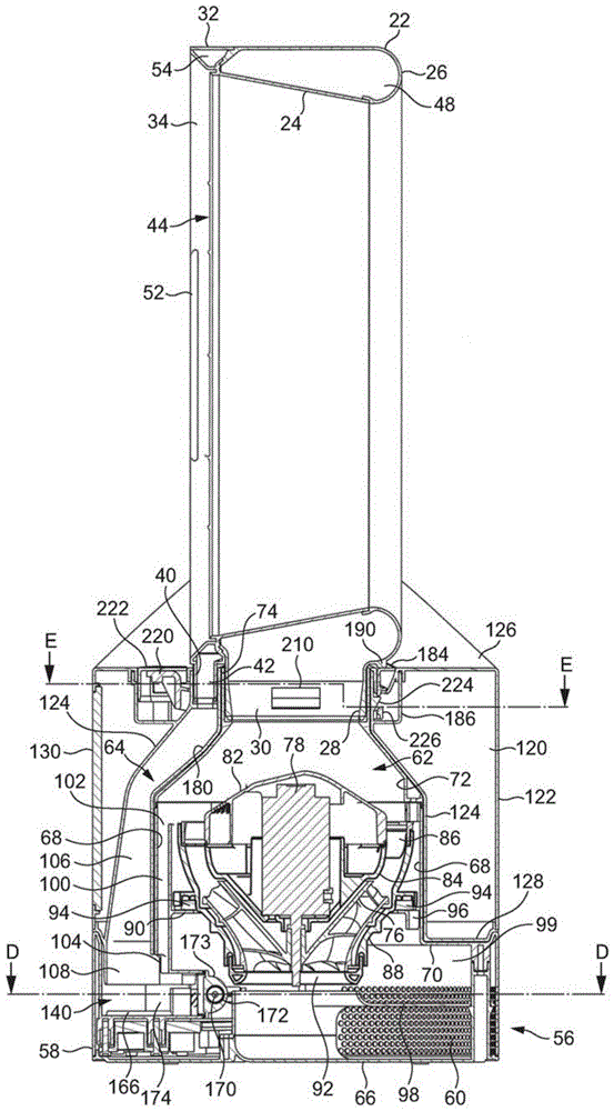
图1到图3是风扇组件的外部视图。在这个实例中,风扇组件是加湿装置10的形式。总体上,加湿装置10包括本体12和喷嘴14,该本体12包括空气入口,空气穿过该空气入口进入加湿装置10,该喷嘴14是安装在本体12上的环形壳体的形式,喷嘴14包括用于从加湿装置10发射空气的多个空气出口。1 to 3 are external views of the fan assembly. In this example, the fan assembly is in the form of
喷嘴14被布置用于发射两股不同的空气流。喷嘴14包括后部区段16和被连接到后部区段16的前部区段18。每个区段16,18是环形的形状,且绕喷嘴14的孔眼20延伸。该孔眼20在中心延伸穿过喷嘴14以致每个区段16,18的中心位于孔眼20的轴线X上。The
在这个实施例中,每个区段16,18具有“跑道”形状,其中每个区段16,18包括位于孔眼20的相对侧上的两个大致直的区段,接合直的区段的上端的弯曲的上部区段和接合直的区段的下端的弯曲的下部区段。然而,区段16,18可具有任何期望的形状;例如区段16,18可以是圆形或椭圆形。在这个实施例中,喷嘴14的高度大于喷嘴的宽度,但喷嘴14可被布置以便喷嘴14的宽度大于喷嘴14的高度。In this embodiment, each
喷嘴14的每个区段16,18限定了一个流动路径,空气流中的相应的一股沿该流动路径穿过。在这个实施例中,喷嘴14的后部区段16限定了第一空气流动路径,第一空气流沿第一空气流动路径穿过喷嘴14,喷嘴14的前部区段18限定了第二空气流动路径,第二空气流沿第二空气流动路径穿过喷嘴14。Each
参考图4(a),喷嘴14的后部区段16包括连接到环形内部壳体区段24且绕其延伸的第一环形外部壳体区段22。每个壳体区段22、24绕孔眼轴线X延伸。每个壳体区段可由多个被连接部件形成,但在这个实施例中每个壳体区段22,24由相应的单个模制部件形成。如图5(a)和5(b)所示,第一外部壳体区段22的后部部分26向内朝向孔眼轴线X弯曲以限定喷嘴14的后端和孔眼20的后部部分。在装配中,第一外部壳体区段22的后部部分26的端部连接到内部壳体区段24的后端,例如使用粘合剂。第一外部壳体区段22包括管状基部28,该管状基部28限定了喷嘴14的第一空气入口30。Referring to FIG. 4( a ), the
喷嘴14的前部区段18也包括连接到环形前部壳体区段34且绕其延伸的第二环形外部壳体区段32。同样,每个壳体区段32、34绕孔眼轴线X延伸且可以由多个被连接部件形成,但在这个实施例中,每个壳体区段32、34是由相应的单个模制部件形成。在这个实施例中,前部壳体区段34包括连接到外部壳体区段22的前端的后部部分36和大致截头锥形形状且从后部部分36远离孔眼轴线X向外张开的前部部分38。前部壳体区段34可以与内部壳体区段24是一体的。第二外部壳体区段32是大致圆柱形形状且在第一外部壳体区段22和前部壳体区段34的前端之间延伸。第二外部壳体区段32包括管状基部40,该管状基部40限定了喷嘴14的第二空气入口42。The
壳体区段24、34一起限定了喷嘴14的第一空气出口44。第一空气出口44由内部壳体区段24和前部壳体区段34的后部部分36的重叠或相对的表面限定,从而第一空气出口44被布置成从喷嘴14的前端发射空气。第一空气出口44是环形槽的形式,其具有绕孔眼轴线X的相对不变的宽度,该宽度在0.5至5mm的范围内。在这个实例中,第一空气出口44具有约1mm的宽度。在内部壳体区段24、34由相应部件形成的情况下,间隔件46可沿第一空气出口44间隔开,用于促使壳体区段24、34的重叠部分分离以控制第一空气出口44的宽度。这些间隔件可与壳体区段24、34的任一个是一体的。在壳体区段24,34是由单个部件形成的情况下,间隔件46由翅片替代,该翅片沿第一空气出口44间隔开用于将内部壳体区段24和前部壳体区段34连接到一起。The
喷嘴14限定了第一环形内部通道48,该第一环形内部通道48用于将第一空气流从第一空气入口30运输到第一空气出口44。该第一内部通道48由第一外部壳体区段22的内表面和内部壳体区段24的内表面限定。锥形环形嘴部50引导第一空气流到第一空气出口44。嘴部50的锥形形状在空气从第一内部通道48流向第一空气出口44时提供了平稳、可控的空气加速。穿过喷嘴14的第一空气流动路径可因此被视为由第一空气入口30,第一内部通道48,嘴部50和第一空气出口40形成。The
前部壳体区段34限定了喷嘴14的多个第二空气出口52。该第二空气出口52也形成在喷嘴14的前端中,每个在孔眼20的相应侧上,例如通过模制或机械加工。每个第二空气出口52位于第一空气出口44的下游。在这个实例中,每个第二空气出口52是槽的形式,其具有相对不变的宽度,该宽度在0.5至5mm的范围内。在这个实例中,每个第二空气出口52具有约1mm的宽度。替代地,每个第二空气出口52可以是形成在喷嘴14的前部壳体区段34中的一排圆孔或槽的形式。The
喷嘴14限定了第二环形内部通道54,该第二环形内部通道54用于将第二空气流从第二空气入口42运输到第二空气出口52。该第二内部通道54由壳体区段32,34的内表面且由第一外部壳体区段22的外表面的前面部分限定。该第二内部通道54在喷嘴14内与第一内部通道48隔离开。穿过喷嘴14的第二空气流动路径可因此被视为由第二空气入口42,第二内部通道54和第二空气出口52形成。The
返回到图4(a),本体12为大体圆柱形形状。本体12包括基座56。该基座56具有外部外壁58,该外壁58是圆柱形形状,且该外壁58包括空气入口60。在这个实例中,该空气入口60包括形成在基座56的外壁58中的多个孔。基座56的前部部分可包括加湿装置10的用户接口。该用户接口示意性地示出在图13中,且在下面进行更详细地描述。用于供应电力到加湿装置10的主电源线(未显示)延伸穿过形成在基座56中的孔。Returning to Figure 4(a), the
该基座56包括第一空气通道62和第二空气通道64,该第一空气通道60用于将第一空气流运输到穿过喷嘴14的第一空气流动路径,该第二空气通道62用于将第二空气流运输到穿过喷嘴14的第二空气流动路径。The
第一空气通道62穿过基座56从空气入口60到喷嘴14的第一空气入口30。还参考图6(a)和6(b),基座56包括连接到外壁58的下端的底壁66,和大体圆柱形的内壁68,其通过凹入环形壁70连接到外壁58。内壁68从环形壁70向上延伸远离。在该实例中,外壁58、内壁68和环形壁70被形成为基座56的单个部件,但是替代地这些壁中的两个或多个可以形成为基座56的单独的部件。上壁被连接到内壁68的上端。上壁具有下部截头锥形区段72和上部圆柱形区段74,其中喷嘴14的基部28被插入到该上部圆柱形区段74中。The
内壁68绕叶轮76延伸,该叶轮64用于产生穿过第一空气通道62的第一空气流。在这个实例中,叶轮76是混流叶轮的形式。该叶轮76连接到从马达78向外延伸用于驱动叶轮76的旋转轴。在这个实施例中,马达78是直流无刷马达,其具有通过驱动电路80响应由用户选择的速度而变化的速度。电机78的最大速度优选地在5000至10000rpm的范围内。电机78被容纳在电机桶内,该桶包括连接到下部部分84的上部部分82。该马达桶的上部部分82包括为具有弯曲叶片的静止盘形式的扩散器86。该扩散器86位于喷嘴14的第一空气入口30的下方。The
电机桶位于大体为截头锥形的叶轮外壳88内,且被安装在其上。该叶轮外壳88被转而安装在从内壁68向内延伸的环形支撑件90上。环形进气构件92被连接到叶轮外壳88的底部用于引导空气流进入叶轮外壳88。环形密封构件94位于叶轮外壳88和环形支撑件90之间以阻止空气穿过叶轮外壳88的外表面周围到进气构件92。该环形支撑件90优选包括引导部分96,该引导部分96用于从驱动电路80引导电线到马达78。基座56还包括引导壁98,用于将空气流从空气入口60引导到进气构件92的进气口。The motor barrel is located within, and is mounted on, a generally
第一空气通道62从空气入口60延伸到进气构件92的进气口。第一空气通道62进而延伸通过叶轮外壳88、内壁68的上端和上壁的区段72、74。The
环形腔体99定位在引导壁98和环形壁70之间。该腔体99具有定位在进气构件92和引导壁98之间的开口,使得腔体99朝向第一空气通道62敞开。该腔体99含有一个固定的空气囊,其用于降低在加湿装置10的使用期间产生的振动到本体12外表面的传递。An
第二空气通道64被布置为接收来自第一空气通道62的空气。第二空气通道64定位为与第一空气通道62相邻。第二空气通道64包括进气管100。参考图6(a)和6(b),进气管100由基座56的内壁68限定。进气管100定位为与第一空气通道62的一部分相邻,且在该实例中在其径向外部。进气管100大致平行于基座56的纵向轴线延伸,该纵向轴线与叶轮76的旋转轴线共线。进气管100具有定位在扩散器86下游并且从扩散器86径向向外的进气口102,以便于接收从扩散器86发出的空气流的一部分,其形成第二空气流。进气管100具有定位在其下端处的出气口104。The
第二空气通道64还包括出气管106,该出气管106被布置为运输第二空气流到喷嘴14的第二空气入口42。该第二空气流被沿大致相反的方向运输穿过进气管100和出气管106。出气管106包括定位在其下端的进气口108和定位在其上端的出气口。喷嘴14的第二外部壳体区段32的基部40被插入到出气管106的出气口,以从出气管106接收第二空气流。The
加湿装置10被配置为在第二空气流进入喷嘴14之前增加第二空气流的湿度。现参考图1到4(a)和图7,加湿装置10包括可移除地安装在基座56上的水箱120。基座56和水箱120一起形成加湿装置10的本体12。该水箱120具有圆柱形外壁122,该外壁122具有和本体12的基座56的外壁58相同的半径,以便当水箱120被安装在基座56上时本体12具有圆柱形外观。水箱120具有管状内壁124,当水箱120被安装在基座56上时,该内壁124围绕基座56的壁68、72、74。外壁122和内壁124与水箱120的环状上壁126和环状下壁128限定了用于储存水的环形体积。水箱120因此围绕叶轮76和马达78,且从而在水箱120被安装在基座56上时围绕第一空气通道62的至少一部分。当水箱120被安装在基座56上时,水箱120的下壁128接合基座56的外壁58和环形壁70的非凹入部分。The
该水箱120优选具有在从2至4升的范围内的容量。窗户130被提供在水箱120的外壁122上,以当水箱120被布置在基座56上时允许用户看见水箱120内的水位。The
参考图9,喷口132可移除地连接到水箱120的下壁128,例如通过配合的螺纹连接。在这个实例中,水箱120通过从基座56移走水箱120且将水箱120颠倒以便喷口132向上突出来填充。喷口132随后被从水箱120拧下,且水通过该喷口132从水箱120分离时暴露的孔被引进水箱120。一旦水箱120被装满,用户将喷口132重新连接到水箱120,将水箱120返回到其未颠倒取向并将水箱120放回基座56上。弹簧阀门134位于喷口132内,该阀门134用于当水箱120再次反转时防止水通过喷口132的排水口136泄漏。阀门134被朝向一位置偏压,在该位置阀门134的裙部接合喷口132的上表面以阻止水从水箱120进入喷口132。Referring to Figure 9, the
水箱120的上壁126包括用于将颠倒的水箱120支撑在工作表面、案台或其它支承表面上的一个或多个支撑件138。在该实例中,两个平行支撑件138被形成在上壁126的周边中,用于支撑颠倒的水箱120。The
还参考图6(a)、6(b)和8,基座56的外壁58、内壁68和环形壁70的凹入部分限定用于从水箱120接收水的水存储器140。基座56包括水处理腔室142,用于在来自水箱120的水进入水存储器140之前处理该水。水处理腔室142定位到水存储器140的一侧,环形壁70的凹入部分中。连接到环形壁70的盖件144包括水处理腔室142的水入口146和水出口148。在该实施例中,水入口146和水出口148的每一个包括多个孔。水出口148定位在盖件144的倾斜表面上,使得水出口148定位在水入口146的下方。盖件144由支撑销150支撑,该支撑销150从环形壁70向上延伸以接合盖件144的下表面。Referring also to FIGS. 6( a ), 6( b ) and 8 , the
盖件144的向上延伸的销152定位在水入口146的孔之间。当水箱120安装在基座56上时,销152突出进入到喷口132,以向上推动阀134打开喷口132,由此允许水在重力作用下流动通过水入口146并进入水处理腔室142。当水处理腔室142装满水时,水流动通过水出口148并进入水存储器140。水处理腔室142容纳阈值抑制剂(threshold inhibitor),譬如聚磷酸盐(polyphosphate)材料的一个或多个滴或丸154,其在水流经水处理腔室142时被加入到水。提供固态的阈值抑制剂意味着阈值抑制剂随着与水处理腔室142中的水长期接触而缓慢溶解。由此,水处理腔室142包括屏障,其防止相对较大块的阈值抑制剂进入水存储器140。在该实例中,该屏障是位于环形壁70和水出口148之间的壁156的形式。The upwardly extending
在水存储器140中,环形壁70包括一对圆孔,每个用于暴露相应的压电换能器160。驱动电路80被配置为促使换能器160以雾化模式振动,以雾化位于水存储器140中的水。在雾化模式中,换能器160可以以频率f1超声振动,该频率f1可以在从1到2MHz的范围内。金属散热器162位于环形壁70和换能器160之间用于将热量传送离开换能器160。孔164形成在基座56的底壁64中,以散发从散热器162辐射的热量。环形密封构件在换能器160和散热器162之间形成不漏水的密封。如图6(a)和6(b)所示,环形壁70中的孔的周边部分166是凸起的,从而表现为一屏障,用于防止已经从水处理腔室142进入水存储器140的任意阈值抑制剂颗粒滞留在换能器160的暴露表面上。In the
水存储器140还包括紫外线辐射(UV)发生器,用于对存储在水存储器140中的水照射。在该实例中,UV发生器为位于UV可透过的管172内的UV灯170的形式,该管172定位在水存储器140中,使得当水存储器140装有水时,水围绕管172。管172定位在水存储器140的与换能器160相对的一侧上。一个或多个反射表面173可以被设置为邻近且优选地围绕管172,用于将从UV灯170发射的紫外线辐射发射到水存储器140中。水存储器140包括挡板174,其沿管172引导从水处理腔室142进入水存储器140的水,使得在使用期间,从水处理腔室142进入水存储器140的水在其被换能器160中的一个雾化之前被用紫外线辐射照射。The
磁液位传感器176位于水存储器140内用于检测水存储器140内的水的水位。取决于水箱120中的水的体积,水存储器140和水处理腔室142可以填充水到最大水位,该最大水位与销152的上表面大致共平面。进气管100的出气口104位于水存储器140内水的最大水位的上方,使得第二空气流在位于水存储器140内的水的表面上方进入水存储器140。The magnetic
出气管106的出气口108定位在换能器160上方,以从水存储器140接收加湿的空气流。该出气管106由水箱120限定。出气管106由水箱120的内壁124和弯曲壁180形成,内壁124绕该弯曲壁180延伸。The
基座56包括接近传感器182,用于检测水箱120已经被安装到基座56上。接近传感器182在图13中示意性地示出。接近传感器182可以是簧片开关的形式,其与定位在水箱120的下壁128上的磁体(未示出)相互作用,以检测水箱120存在还是不存在基座56上。如图7(a)、(b)和11所示,当水箱120安装在基座56上时,内壁124和弯曲壁180围绕基座56的上壁,以暴露上壁的上部圆柱形区段74的敞开上端。水箱120可包括手柄184,该手柄可帮助水箱120从基座56的移除。手柄184可以枢转地连接到水箱120,以便于可以相对于水箱120在收起位置和展开位置之间运动,在收起位置中,手柄184被容纳在水箱120的上壁126的凹入区段186内,而在展开位置中,手柄184被升起到水箱120的上壁126之上。参考图12(a)和12(b),一个或多个弹性元件188,譬如扭力弹簧,可以被提供以将手柄184朝向其展开位置偏压,如图7(a)和7(b)所示。The
当喷嘴14被安装在本体12上时,喷嘴14的第一外部壳体区段22的基部28被定位在基座56的上壁的上部圆柱形区段74的敞开端部之上,且喷嘴14的第二外部壳体区段32的基部40被定位在水箱120的出气管106的敞开上端之上。用户然后朝向本体12推压喷嘴14。如图10所示,销190形成在喷嘴14的第一外部壳体区段22的下表面上,第一外部壳体区段22的基部28的紧邻后方。当喷嘴14朝向本体12运动时,销190克服弹性元件188的偏压力朝向其收起位置推动手柄184。当喷嘴14的基部28、40被完全插入到本体12中时,环形密封构件192在基部28、40的端部和形成在基座56的上壁的上部圆柱形区段74中和出气管106中的环形台肩194之间形成气密密封。水箱120的上壁126具有凹形形状,使得当喷嘴14被安装在本体12上时,水箱120围绕喷嘴14的下部部分。这不仅可以允许水箱120的容量增加,还可以为加湿装置10提供紧凑的外观。When the
本体12包括用于将喷嘴14可释放地保持在本体12上的机构。图4(a)、11和12(a)示出了当喷嘴14被保持在本体12上时该机构的第一构造,而图4(b)和12(b)示出了当喷嘴14从本体12释放时该机构的第二构造。用于将喷嘴14可释放地保持在本体12上的机构包括定位在环形外壳202的直径相对侧上的一对制动器200。每一个制动器200具有大体L形横截面。每一个制动器200可以在用于保持喷嘴14在本体12上的展开位置和收起位置之间枢转运动。弹性元件204,譬如扭力弹簧,被定位在外壳202中用于将制动器200朝向它们的展开位置偏压。The
在该实例中,水箱120包括用于将喷嘴14可释放地保持在本体12上的机构。外壳202包括一对直径相对的孔206,当水箱120被安装在基座56上时,孔206与形成在基座56的上壁的上部圆柱形区段74上的相似形状的孔208对准。喷嘴14的基部28的外表面包括一对直径相对的凹部210,其在喷嘴14被安装在本体12上时与孔206、208对准。当制动器200处于它们的展开位置时,制动器200的端部被弹性元件204推动穿过孔206、208,以进入喷嘴14的凹部210中。制动器200的端部接合喷嘴14的基部28的凹入外表面,以防止喷嘴14被从本体12脱离,例如如果加湿装置10被用户通过抓住喷嘴14而提起。In this example, the
本体12包括可按压卡扣件220,其可操作以通过将制动器200运动离开凹部210,而将该机构从第一构造运动到第二构造,从而将喷嘴14从本体12释放。卡扣件220被安装在外壳202中,用于绕一轴线枢转运动,该轴线正交于制动器200在其收起和展开位置之间枢转所绕的轴线。卡扣件220可以响应于用户按压定位在本体12上的按钮222而从如图4(a)、11和12(a)所示的收起位置运动到如图4(b)、7(a)、7(b)和12(b)所示的展开位置。在该实例中,按钮222定位在水箱120的上壁126上且位于卡扣件220的前部区段的上方。压缩弹簧或其它弹性元件可以被设置在卡扣件220的前部区段之下,用于将卡扣件220迫向收起位置。卡扣件220的旋转轴线定位为靠近卡扣件的前部区段,使得当卡扣件220向其展开位置运动时,卡扣件220迫使制动器200克服弹性元件204的偏压力枢转离开凹部210。The
本体12被配置为当用户释放按钮222时将卡扣件220保持在其展开位置。在该实例中,水箱120的外壳202包括楔形物224,当卡扣件220朝向其展开位置运动时,位于卡扣件220后部区段上的钩226在该楔形物上滑动。在展开位置,钩226的端部扣在楔形物224的锥形侧表面上以接合楔形物224的上表面,导致卡扣件220被保持在其展开位置。当钩226在楔形物224的上表面上运动时,钩226接合手柄184的底部,且迫使手柄184向上离开水箱120的凹入区段186。这进而导致手柄184将喷嘴14稍稍推离本体12,向用户提供喷嘴14已被从本体12释放的可视指示。作为对在水箱120和卡扣件220上具有协作以将卡扣件220保持在其展开位置的结构的替代,一个或多个磁体可以被使用以将卡扣件220保持在其展开位置。The
在其展开位置,卡扣件220将制动器200保持在其收起位置中,如图4(b)和12(b)所示,以允许用户将喷嘴14从该本体12移除。当喷嘴14被从本体12提起时,弹性元件188将手柄184迫到其展开位置。用户于是可以使用手柄184将水箱120从基座56提起,以允许水箱120按需要被填充或清洁。In its deployed position, the
一旦水箱120被装满或清洁,用户将水箱120放在基座56上,且然后将喷嘴14放回本体12上。当喷嘴14的基部28、40被推入本体12中时,喷嘴14上的销190接合手柄184并将手柄184推回到其在水箱120的凹入区段186内的收起位置。当手柄184运动到其收起位置时,它接合卡扣件220上的钩226并将钩226推离楔形物224的上表面以将卡扣件220从其展开位置释放。当钩226运动离开楔形物224时,弹性元件204将制动器推向其展开位置,以将喷嘴14保持在本体12上。当制动器200朝向其展开位置运动时,制动器200将卡扣件220移回到其收起位置。Once the
用于控制加湿装置的操作的用户接口位于本体12的基座56的外壁58上。图13示意性地示出了用于加湿装置10的控制系统,该控制系统包括这个用户接口和加湿装置10的其他电气部件。在这个实施例中,用户接口包括多个用户可操作按钮240a、240b和240c,和显示器242。该第一按钮240a用于激活或关闭马达78,第二按钮240b用于设定马达78的速度,由此设定叶轮76的旋转速度。第三按钮240c用于设定加湿装置10所在其中的环境(如房间,办公室或其他家庭环境)的相对湿度的期望水平。例如,期望的相对湿度的水平可通过第三按钮240c的重复促动在20℃处的30%至80%的范围内选择。该显示器242提供了当前选择的相对湿度水平的指示。A user interface for controlling the operation of the humidification device is located on the
用户接口还包括用户接口电路244,该用户接口电路144根据按钮中的一个的促动输出控制信号到驱动电路80,并接收由驱动电路80输出的控制信号。用户接口还可包括一个或多个发光二级管(LED),该发光二级管用于根据加湿装置的状态提供视觉警告。例如,第一LED 246a可由驱动电路80点亮指示水箱120已经排空,如通过驱动电路80接收的来自液位传感器176的信号所指示。The user interface also includes a
湿度传感器248也被提供用于检测外部环境中的空气的相对湿度,且用于供应检测到的相对湿度的指示信号到驱动电路80。在这个实施例中,该湿度传感器248可位于空气入口60的紧邻后方以检测被抽吸进入加湿装置10中的空气流的相对湿度。用户接口可包括第二LED 246b,当来自湿度传感器248的输出指示进入加湿装置10中的空气流的相对湿度HD等于或大于用户设定的期望相对湿度HS时,该LED 246b由驱动电路80点亮。A
还参考图14,为了操作加湿装置10,用户促动第一按钮240a。按钮240a的该操作被传递到驱动电路80,响应于此,驱动电路80促动UV灯170以对存储在水存储器140中的水照射。在该实例中,驱动电路80同时激活马达78以旋转叶轮76。叶轮76的旋转导致空气穿过空气入口60被抽吸进入本体12中。空气流穿过叶轮外壳88和扩散器86。在扩散器86的下游,从扩散器86发射的空气的一部分穿过进气口102进入进气管100,而从扩散器86发射的空气的剩余部分被沿第一空气通道62输送到喷嘴14的第一空气入口30。叶轮76和马达78可由此被视为产生第一空气流,该第一空气流通过第一空气通道62被运输到喷嘴14且通过第一空气入口30进入喷嘴14。Referring also to Figure 14, in order to operate the
第一空气流在喷嘴14的后部区段16的基部处进入第一内部通道48。在第一内部通道48的基部处,空气流被分为两股气流,该两股气流绕喷嘴14的孔眼20沿相反方向行进。当气流穿过第一内部通道48时,空气进入喷嘴14的嘴部50。进入嘴部50中的该空气流优选绕喷嘴14的孔眼20大致均匀。该嘴部50引导空气流朝向喷嘴14的第一空气出口44,空气流从第一空气出口44从加湿装置10发射。The first air flow enters the first
该空气流从第一空气出口40发射导致次空气流通过卷吸来自外部环境的空气产生,特别地来自第一空气出口44周围区域和来自喷嘴14的后面周围。这些次空气流的一些穿过喷嘴14的孔眼20,而该次空气流的剩余部分被卷吸在从喷嘴14的前部中的第一空气出口发射的空气流内。This air flow is emitted from the
如上所述,随着叶轮76的旋转,空气穿过进气管100的进气口102进入第二空气通道64,以形成第二空气流。第二空气流流经进气管100且被通过出气口104发射到存储在水存储器140中的水的上方。该第二空气流从出气口104的发射搅动存储在水存储器140中的水以产生沿和绕UV灯170的水运动,增加被UV灯170照射的水的体积。在存储的水中阈值抑制剂的存在导致阈值抑制剂的薄层形成在管172和换能器160的暴露到存储的水的表面上,抑制水垢在这些表面上的沉淀。这可以延长换能器160的工作寿命并抑制由UV灯170对存储水的照射的任何能量降级。As described above, as the
除了通过第二空气流140搅动存储在水存储器140中的水之外,搅动还可以通过搅动模式下的换能器160的振动来执行,该搅动模式的振动不足以使存储的水雾化。例如取决于基座56的换能器160的尺寸和数量,存储的水的搅动可以仅通过换能器160以降低的第二频率f2和/或以降低的幅度、或以不同的占空比的振动来执行。在该情况下,驱动电路80可以配置为在通过UV灯170对存储的水照射的同时,以该搅动模式促动换能器160的振动。In addition to agitating the water stored in the
该存储水的搅动和照射持续一时间段,该时间段足以使水存储器140中的细菌水平降低期望数量。在该实例中,水存储器140具有200ml的最大容量,且存储水的搅动和照射持续60秒的时间段,然后存储水的雾化开始。该时间段的持续时间可以取决于例如存储水的搅动程度、水存储器140的容量以及存储水的照射强度而加长或缩短,且从而取决于这些变量,该时间段的持续时间可以采取在10到300秒范围内的任何值,以实现存储水中的细菌数量的期望降低。The agitation and irradiation of the stored water is continued for a period of time sufficient to reduce the level of bacteria in the
在该时间段结束时,驱动电路80促动换能器160以雾化模式振动,以雾化存储在水存储器140中的水。这造成位于水存储器140内的水的上方的空气中的水滴。在存储水被换能器160的振动独自预先搅动的情况下,马达78在该时间段结束时也被启动。At the end of this time period, the
随着水存储器140内的水雾化,水存储器140不断地被经由水处理腔室142接收自水箱120的水重新装满,以便水存储器140内的水的水位保持大致不变同时水箱120内的水的水位逐渐下降。当水从水处理腔室142(在其中阈值抑制剂被加入水)进入水存储器140时,它被壁174引导以沿着管172流动,使得它在被雾化之前被用紫外线辐射照射。As the water in the
随着叶轮76的旋转,空中的水滴被夹带在从进气管100的出气口104发射的第二空气流中。该目前湿的第二空气流向上穿过第二空气通道64的出气管106到喷嘴14的第二空气入口42,且进入喷嘴14的前部区段18内的第二内部通道54。As the
在第二内部通道54的基座处,第二空气流被分成两股气流,该两股气流绕喷嘴14的孔眼20沿相反方向行进。当该气流穿过第二内部通道54时,每股气流从位于第一空气出口44前面的喷嘴14的前端中的第二空气出口52中的相应一个发射。该被发射的第二空气流在通过第一空气流从喷嘴14的发射而产生的空气流内被运输远离加湿装置10,从而使湿气流被在距加湿装置10几米的距离处迅速体验到。At the base of the second
湿空气流从喷嘴14发射直到由湿度传感器248检测到进入加湿装置10的空气流的相对湿度HD比用户使用第三按钮240c选定的相对湿度水平HS高在20℃处的1%为止。于是湿空气流从喷嘴14的发射可通过驱动电路80,优选通过改变换能器160的振动模式,而终止。例如,换能器160的振动频率可以被降低到频率f3,其中f1>f3≥0,在该频率f3之下存储水的雾化没有被执行。替代地,换能器160振动的幅度可以被降低。可选择地,马达78也可被停止从而没有空气流从喷嘴14发射。然而,当湿度传感器248定位为紧密靠近马达78时,最好马达78继续运行以避免在湿度传感器248的局部环境中的不期望的温度波动。此外,优选继续运行马达78以继续搅动存储在水存储器140中的水。UV灯170的操作也继续。The stream of moist air is emitted from the
作为终止从加湿装置10发射湿空气流的结果,通过湿度传感器248检测到的相对湿度HD开始下降。一旦湿度传感器248的局部环境的空气的相对湿度下降到比用户选定的相对湿度水平HS低在20℃处的1%,驱动电路80以雾化模式重新启动换能器160的振动。如果马达78被停止,驱动电路80同时重新启动马达78。如之前,湿空气流从喷嘴14发射直到湿度传感器248检测到的相对湿度HD比用户选定的相对湿度水平HS高在20℃处的1%。As a result of terminating the emission of humid air flow from
用于保持检测到的湿度水平在用户选择的水平附近的这个换能器160(和可选择地马达78)的促动程序继续进行直到按钮240a再次被促动,或直到接收自水位传感器176的信号指示水存储器140内的水的水位已经下降到最小水位以下。如果按钮240a被促动,或一旦从水位传感器176接收到该信号,驱动电路80关闭马达78、换能器160和UV灯170以关闭加湿装置。驱动电路80还响应于从接近传感器182接收的指示水箱120已经被从基座56移除的信号而关闭加湿装置10的这些部件。The actuation routine of this transducer 160 (and optionally the motor 78 ) to maintain the detected humidity level near the user-selected level continues until the
Claims (17)
Applications Claiming Priority (3)
| Application Number | Priority Date | Filing Date | Title |
|---|---|---|---|
| GB1203889.9A GB2500005B (en) | 2012-03-06 | 2012-03-06 | A method of generating a humid air flow |
| GB1203889.9 | 2012-03-06 | ||
| CN201310071220.9A CN103306950B (en) | 2012-03-06 | 2013-03-06 | humidifier |
Related Parent Applications (1)
| Application Number | Title | Priority Date | Filing Date |
|---|---|---|---|
| CN201310071220.9A Division CN103306950B (en) | 2012-03-06 | 2013-03-06 | humidifier |
Publications (2)
| Publication Number | Publication Date |
|---|---|
| CN107036220A CN107036220A (en) | 2017-08-11 |
| CN107036220B true CN107036220B (en) | 2022-06-14 |
Family
ID=46003172
Family Applications (3)
| Application Number | Title | Priority Date | Filing Date |
|---|---|---|---|
| CN201710100650.7A Active CN107036220B (en) | 2012-03-06 | 2013-03-06 | humidifier |
| CN201310071220.9A Active CN103306950B (en) | 2012-03-06 | 2013-03-06 | humidifier |
| CN201320101036XU Expired - Lifetime CN203130436U (en) | 2012-03-06 | 2013-03-06 | Humidifying device |
Family Applications After (2)
| Application Number | Title | Priority Date | Filing Date |
|---|---|---|---|
| CN201310071220.9A Active CN103306950B (en) | 2012-03-06 | 2013-03-06 | humidifier |
| CN201320101036XU Expired - Lifetime CN203130436U (en) | 2012-03-06 | 2013-03-06 | Humidifying device |
Country Status (14)
| Country | Link |
|---|---|
| US (2) | US9752789B2 (en) |
| EP (1) | EP2823232B1 (en) |
| JP (1) | JP5635147B2 (en) |
| KR (2) | KR20160045934A (en) |
| CN (3) | CN107036220B (en) |
| AU (1) | AU2013229283B2 (en) |
| CA (1) | CA2866138A1 (en) |
| GB (2) | GB2500005B (en) |
| IN (1) | IN2014DN07715A (en) |
| MY (1) | MY168639A (en) |
| RU (1) | RU2612560C2 (en) |
| SG (1) | SG11201405366XA (en) |
| TW (1) | TWM463332U (en) |
| WO (1) | WO2013132217A1 (en) |
Families Citing this family (84)
| Publication number | Priority date | Publication date | Assignee | Title |
|---|---|---|---|---|
| WO2010100462A1 (en) | 2009-03-04 | 2010-09-10 | Dyson Technology Limited | Humidifying apparatus |
| GB2493506B (en) | 2011-07-27 | 2013-09-11 | Dyson Technology Ltd | A fan assembly |
| WO2013014419A2 (en) | 2011-07-27 | 2013-01-31 | Dyson Technology Limited | A fan assembly |
| GB201119500D0 (en) | 2011-11-11 | 2011-12-21 | Dyson Technology Ltd | A fan assembly |
| GB2500005B (en) | 2012-03-06 | 2014-08-27 | Dyson Technology Ltd | A method of generating a humid air flow |
| GB2500012B (en) | 2012-03-06 | 2016-07-06 | Dyson Technology Ltd | A Humidifying Apparatus |
| RU2606194C2 (en) | 2012-03-06 | 2017-01-10 | Дайсон Текнолоджи Лимитед | Fan unit |
| GB2500010B (en) | 2012-03-06 | 2016-08-24 | Dyson Technology Ltd | A humidifying apparatus |
| GB2500011B (en) | 2012-03-06 | 2016-07-06 | Dyson Technology Ltd | A Humidifying Apparatus |
| GB2500017B (en) | 2012-03-06 | 2015-07-29 | Dyson Technology Ltd | A Humidifying Apparatus |
| BR302013003358S1 (en) | 2013-01-18 | 2014-11-25 | Dyson Technology Ltd | CONFIGURATION APPLIED ON HUMIDIFIER |
| AU350140S (en) | 2013-01-18 | 2013-08-13 | Dyson Technology Ltd | Humidifier or fan |
| AU350179S (en) | 2013-01-18 | 2013-08-15 | Dyson Technology Ltd | Humidifier or fan |
| AU350181S (en) | 2013-01-18 | 2013-08-15 | Dyson Technology Ltd | Humidifier or fan |
| GB2510195B (en) | 2013-01-29 | 2016-04-27 | Dyson Technology Ltd | A fan assembly |
| KR101762665B1 (en) | 2013-01-29 | 2017-07-28 | 다이슨 테크놀러지 리미티드 | A fan assembly |
| CA152657S (en) | 2013-03-07 | 2014-05-20 | Dyson Technology Ltd | Fan |
| CA152655S (en) | 2013-03-07 | 2014-05-20 | Dyson Technology Ltd | Fan |
| CA152658S (en) | 2013-03-07 | 2014-05-20 | Dyson Technology Ltd | Fan |
| CA152656S (en) | 2013-03-07 | 2014-05-20 | Dyson Technology Ltd | Fan |
| USD729372S1 (en) | 2013-03-07 | 2015-05-12 | Dyson Technology Limited | Fan |
| BR302013004394S1 (en) | 2013-03-07 | 2014-12-02 | Dyson Technology Ltd | CONFIGURATION APPLIED TO FAN |
| CA154723S (en) | 2013-08-01 | 2015-02-16 | Dyson Technology Ltd | Fan |
| CA154722S (en) | 2013-08-01 | 2015-02-16 | Dyson Technology Ltd | Fan |
| TWD172707S (en) | 2013-08-01 | 2015-12-21 | 戴森科技有限公司 | A fan |
| GB2518638B (en) | 2013-09-26 | 2016-10-12 | Dyson Technology Ltd | Humidifying apparatus |
| KR102143436B1 (en) | 2014-03-20 | 2020-08-11 | 다이슨 테크놀러지 리미티드 | Attachment for a hand held appliance |
| GB2526049B (en) | 2014-03-20 | 2017-04-12 | Dyson Technology Ltd | Attachment for a hand held appliance |
| GB2528709B (en) | 2014-07-29 | 2017-02-08 | Dyson Technology Ltd | Humidifying apparatus |
| GB2528708B (en) | 2014-07-29 | 2016-06-29 | Dyson Technology Ltd | A fan assembly |
| GB2528704A (en) | 2014-07-29 | 2016-02-03 | Dyson Technology Ltd | Humidifying apparatus |
| TWD173929S (en) * | 2015-01-30 | 2016-02-21 | 戴森科技有限公司 | A fan |
| TWD179707S (en) * | 2015-01-30 | 2016-11-21 | 戴森科技有限公司 | A fan |
| TWD173931S (en) * | 2015-01-30 | 2016-02-21 | 戴森科技有限公司 | A fan |
| TWD173928S (en) * | 2015-01-30 | 2016-02-21 | 戴森科技有限公司 | A fan |
| TWD173932S (en) * | 2015-01-30 | 2016-02-21 | 戴森科技有限公司 | A fan |
| TWD173930S (en) * | 2015-01-30 | 2016-02-21 | 戴森科技有限公司 | A fan |
| GB2540164A (en) * | 2015-07-07 | 2017-01-11 | Dyson Technology Ltd | Humidifying apparatus |
| GB2540166B (en) * | 2015-07-07 | 2019-06-12 | Dyson Technology Ltd | Humidifying apparatus |
| GB2540165B (en) * | 2015-07-07 | 2019-09-11 | Dyson Technology Ltd | Humidifying apparatus |
| CH711362B1 (en) * | 2015-07-29 | 2019-11-15 | Tecan Schweiz Ag | Relative humidity control unit. |
| USD804007S1 (en) * | 2015-11-25 | 2017-11-28 | Vornado Air Llc | Air circulator |
| KR102101642B1 (en) | 2016-03-24 | 2020-04-17 | 다이슨 테크놀러지 리미티드 | Attachments for portable instruments |
| KR102101643B1 (en) | 2016-03-24 | 2020-04-17 | 다이슨 테크놀러지 리미티드 | Attachments for portable instruments |
| GB2548616B (en) * | 2016-03-24 | 2020-02-19 | Dyson Technology Ltd | An attachment for a hand held appliance |
| CN106482271B (en) * | 2016-10-20 | 2019-04-16 | 圆融健康科技(深圳)有限公司 | Humidifier and humidifier degerming air-humidification method |
| RU177089U1 (en) * | 2017-04-20 | 2018-02-07 | Волкаст Лимитед | A humidifier for practicing yoga, callanetics and stretching, preferably |
| US11384956B2 (en) | 2017-05-22 | 2022-07-12 | Sharkninja Operating Llc | Modular fan assembly with articulating nozzle |
| KR102361034B1 (en) * | 2017-09-13 | 2022-02-10 | 주식회사 위니아딤채 | Water supply device for air washer |
| US10760803B2 (en) | 2017-11-21 | 2020-09-01 | Emerson Climate Technologies, Inc. | Humidifier control systems and methods |
| USD895781S1 (en) * | 2017-12-11 | 2020-09-08 | Dyson Technology Limited | Fan |
| USD888219S1 (en) * | 2017-12-11 | 2020-06-23 | Dyson Technology Limited | Fan |
| USD888928S1 (en) * | 2017-12-11 | 2020-06-30 | Dyson Technology Limited | Fan |
| USD888929S1 (en) * | 2017-12-11 | 2020-06-30 | Dyson Technology Limited | Fan |
| USD888927S1 (en) * | 2017-12-11 | 2020-06-30 | Dyson Technology Limited | Fan |
| USD888220S1 (en) * | 2017-12-11 | 2020-06-23 | Dyson Technology Limited | Fan |
| US11370529B2 (en) * | 2018-03-29 | 2022-06-28 | Walmart Apollo, Llc | Aerial vehicle turbine system |
| US10926210B2 (en) | 2018-04-04 | 2021-02-23 | ACCO Brands Corporation | Air purifier with dual exit paths |
| US11371726B2 (en) | 2018-04-20 | 2022-06-28 | Emerson Climate Technologies, Inc. | Particulate-matter-size-based fan control system |
| WO2019204791A1 (en) | 2018-04-20 | 2019-10-24 | Emerson Climate Technologies, Inc. | Hvac filter usage analysis system |
| WO2019204789A1 (en) | 2018-04-20 | 2019-10-24 | Emerson Climate Technologies, Inc. | Indoor air quality sensor calibration systems and methods |
| US11421901B2 (en) | 2018-04-20 | 2022-08-23 | Emerson Climate Technologies, Inc. | Coordinated control of standalone and building indoor air quality devices and systems |
| US11486593B2 (en) | 2018-04-20 | 2022-11-01 | Emerson Climate Technologies, Inc. | Systems and methods with variable mitigation thresholds |
| US12078373B2 (en) | 2018-04-20 | 2024-09-03 | Copeland Lp | Systems and methods for adjusting mitigation thresholds |
| US11226128B2 (en) | 2018-04-20 | 2022-01-18 | Emerson Climate Technologies, Inc. | Indoor air quality and occupant monitoring systems and methods |
| WO2019204786A1 (en) | 2018-04-20 | 2019-10-24 | Emerson Climate Technologies, Inc. | Computerized hvac filter evaluation system |
| WO2019204785A1 (en) | 2018-04-20 | 2019-10-24 | Emerson Climate Technologies, Inc. | Particulate-matter-size-based fan control system |
| US11609004B2 (en) | 2018-04-20 | 2023-03-21 | Emerson Climate Technologies, Inc. | Systems and methods with variable mitigation thresholds |
| USD913467S1 (en) | 2018-06-12 | 2021-03-16 | ACCO Brands Corporation | Air purifier |
| JP7213682B2 (en) * | 2018-12-27 | 2023-01-27 | 日機装株式会社 | humidifier |
| GB201900016D0 (en) * | 2019-01-02 | 2019-02-13 | Dyson Technology Ltd | Air treatment apparatus |
| GB201900022D0 (en) * | 2019-01-02 | 2019-02-13 | Dyson Technology Ltd | Air treatment apparatus |
| KR102715124B1 (en) * | 2019-03-04 | 2024-10-10 | 엘지전자 주식회사 | Indoor unit for air conditioner |
| KR102610034B1 (en) * | 2019-03-28 | 2023-12-06 | 엘지전자 주식회사 | Air conditioner and method for controlling the same |
| KR102639778B1 (en) * | 2019-09-06 | 2024-02-21 | 엘지전자 주식회사 | Indoor unit for air conditioner |
| KR102638178B1 (en) * | 2019-09-06 | 2024-02-16 | 엘지전자 주식회사 | Indoor unit for air conditioner |
| USD965129S1 (en) * | 2020-12-17 | 2022-09-27 | Shenzhen OriginX Technology Co., LTD. | Leafless air purifier |
| USD942606S1 (en) * | 2021-03-08 | 2022-02-01 | Ruochen Fu | Heating and cooling fan |
| USD939072S1 (en) * | 2021-03-08 | 2021-12-21 | Ruochen Fu | Heating and cooling fan |
| USD1057918S1 (en) | 2021-06-23 | 2025-01-14 | Sharkninja Operating Llc | Air purifier |
| CN115200098B (en) * | 2022-06-22 | 2024-01-23 | 珠海格力电器股份有限公司 | Water tank for humidifying air conditioner and humidifying air conditioner |
| USD1079922S1 (en) | 2022-11-30 | 2025-06-17 | Vornado Air, Llc | Tower fan |
| EP4651762A1 (en) | 2023-01-19 | 2025-11-26 | SharkNinja Operating LLC | Hair care appliance with powered attachment |
| US20240245190A1 (en) | 2023-01-19 | 2024-07-25 | Sharkninja Operating Llc | Identification of hair care appliance attachments |
Citations (6)
| Publication number | Priority date | Publication date | Assignee | Title |
|---|---|---|---|---|
| US5859952A (en) * | 1995-11-03 | 1999-01-12 | Slant/Fin Corporation | Humidifier with UV anti-contamination provision |
| JP2003161473A (en) * | 2002-10-21 | 2003-06-06 | Ucan Co Ltd | Humidifier and seal member for humidifier |
| JP3099926U (en) * | 2003-08-19 | 2004-04-22 | 株式会社 ヒート | Drinking water server |
| CN1724950A (en) * | 2004-05-24 | 2006-01-25 | 斯兰特/芬公司 | Humidifier with improved uv disinfection |
| CN2796714Y (en) * | 2005-04-29 | 2006-07-19 | 中国农业大学 | Counter flow stirring type ultraviolet ray sterilizer |
| CN101825324A (en) * | 2009-03-04 | 2010-09-08 | 戴森技术有限公司 | Humidifying apparatus |
Family Cites Families (606)
| Publication number | Priority date | Publication date | Assignee | Title |
|---|---|---|---|---|
| GB601222A (en) | 1944-10-04 | 1948-04-30 | Berkeley & Young Ltd | Improvements in, or relating to, electric fans |
| US284962A (en) | 1883-09-11 | William huston | ||
| GB593828A (en) | 1945-06-14 | 1947-10-27 | Dorothy Barker | Improvements in or relating to propeller fans |
| GB191322235A (en) | 1913-10-02 | 1914-06-11 | Sidney George Leach | Improvements in the Construction of Electric Fans. |
| US1357261A (en) | 1918-10-02 | 1920-11-02 | Ladimir H Svoboda | Fan |
| US1767060A (en) | 1928-10-04 | 1930-06-24 | W H Addington | Electric motor-driven desk fan |
| US2014185A (en) | 1930-06-25 | 1935-09-10 | Martin Brothers Electric Compa | Drier |
| GB383498A (en) | 1931-03-03 | 1932-11-17 | Spontan Ab | Improvements in or relating to fans, ventilators, or the like |
| US1896869A (en) | 1931-07-18 | 1933-02-07 | Master Electric Co | Electric fan |
| US2035733A (en) | 1935-06-10 | 1936-03-31 | Marathon Electric Mfg | Fan motor mounting |
| US2071266A (en) | 1935-10-31 | 1937-02-16 | Continental Can Co | Lock top metal container |
| US2185718A (en) | 1936-06-24 | 1940-01-02 | American Blower Corp | Fan |
| US2210458A (en) | 1936-11-16 | 1940-08-06 | Lester S Keilholtz | Method of and apparatus for air conditioning |
| US2115883A (en) | 1937-04-21 | 1938-05-03 | Sher Samuel | Lamp |
| US2258961A (en) | 1939-07-26 | 1941-10-14 | Prat Daniel Corp | Ejector draft control |
| US2336295A (en) | 1940-09-25 | 1943-12-07 | Reimuller Caryl | Air diverter |
| US2363839A (en) | 1941-02-05 | 1944-11-28 | Demuth Charles | Unit type air conditioning register |
| US2295502A (en) | 1941-05-20 | 1942-09-08 | Lamb Edward | Heater |
| GB641622A (en) | 1942-05-06 | 1950-08-16 | Fernan Oscar Conill | Improvements in or relating to hair drying |
| US2433795A (en) | 1945-08-18 | 1947-12-30 | Westinghouse Electric Corp | Fan |
| US2476002A (en) | 1946-01-12 | 1949-07-12 | Edward A Stalker | Rotating wing |
| US2547448A (en) | 1946-02-20 | 1951-04-03 | Demuth Charles | Hot-air space heater |
| US2473325A (en) | 1946-09-19 | 1949-06-14 | E A Lab Inc | Combined electric fan and air heating means |
| US2544379A (en) | 1946-11-15 | 1951-03-06 | Oscar J Davenport | Ventilating apparatus |
| US2488467A (en) | 1947-09-12 | 1949-11-15 | Lisio Salvatore De | Motor-driven fan |
| GB633273A (en) | 1948-02-12 | 1949-12-12 | Albert Richard Ponting | Improvements in or relating to air circulating apparatus |
| US2510132A (en) | 1948-05-27 | 1950-06-06 | Morrison Hackley | Oscillating fan |
| GB661747A (en) | 1948-12-18 | 1951-11-28 | British Thomson Houston Co Ltd | Improvements in and relating to oscillating fans |
| US2620127A (en) | 1950-02-28 | 1952-12-02 | Westinghouse Electric Corp | Air translating apparatus |
| US2583374A (en) | 1950-10-18 | 1952-01-22 | Hydraulic Supply Mfg Company | Exhaust fan |
| FR1033034A (en) | 1951-02-23 | 1953-07-07 | Articulated stabilizer support for fan with flexible propellers and variable speeds | |
| US2711682A (en) | 1951-08-04 | 1955-06-28 | Ilg Electric Ventilating Co | Power roof ventilator |
| US2755106A (en) | 1952-07-26 | 1956-07-17 | Gen Electric | Pivoted floating latch for suction cleaner tube or hose coupling |
| US2813673A (en) | 1953-07-09 | 1957-11-19 | Gilbert Co A C | Tiltable oscillating fan |
| US2838229A (en) | 1953-10-30 | 1958-06-10 | Roland J Belanger | Electric fan |
| US2765977A (en) | 1954-10-13 | 1956-10-09 | Morrison Hackley | Electric ventilating fans |
| FR1119439A (en) | 1955-02-18 | 1956-06-20 | Enhancements to portable and wall fans | |
| US2830779A (en) | 1955-02-21 | 1958-04-15 | Lau Blower Co | Fan stand |
| NL110393C (en) | 1955-11-29 | 1965-01-15 | Bertin & Cie | |
| CH346643A (en) | 1955-12-06 | 1960-05-31 | K Tateishi Arthur | Electric fan |
| US2808198A (en) | 1956-04-30 | 1957-10-01 | Morrison Hackley | Oscillating fans |
| GB863124A (en) | 1956-09-13 | 1961-03-15 | Sebac Nouvelle Sa | New arrangement for putting gases into movement |
| BE560119A (en) | 1956-09-13 | |||
| FR1192292A (en) | 1956-11-29 | 1959-10-26 | Electrolux Ab | Coupling device, especially for flexible vacuum cleaner hose and other applications |
| US2922570A (en) | 1957-12-04 | 1960-01-26 | Burris R Allen | Automatic booster fan and ventilating shield |
| BE571912A (en) | 1958-07-10 | |||
| US2984089A (en) | 1958-11-12 | 1961-05-16 | Amana Refrigeration Inc | Air conditioner |
| US3004403A (en) | 1960-07-21 | 1961-10-17 | Francis L Laporte | Refrigerated space humidification |
| DE1291090B (en) | 1963-01-23 | 1969-03-20 | Schmidt Geb Halm Anneliese | Device for generating an air flow |
| DE1457461A1 (en) | 1963-10-01 | 1969-02-20 | Siemens Elektrogeraete Gmbh | Suitcase-shaped hair dryer |
| GB1022529A (en) | 1963-12-16 | 1966-03-16 | Philips Nv | Devices for locking a tube end inserted into a socket |
| FR1387334A (en) | 1963-12-21 | 1965-01-29 | Hair dryer capable of blowing hot and cold air separately | |
| US3270655A (en) | 1964-03-25 | 1966-09-06 | Howard P Guirl | Air curtain door seal |
| US3518776A (en) | 1967-06-03 | 1970-07-07 | Bremshey & Co | Blower,particularly for hair-drying,laundry-drying or the like |
| US3487555A (en) | 1968-01-15 | 1970-01-06 | Hoover Co | Portable hair dryer |
| US3495343A (en) | 1968-02-20 | 1970-02-17 | Rayette Faberge | Apparatus for applying air and vapor to the face and hair |
| JPS467230Y1 (en) | 1968-06-28 | 1971-03-15 | ||
| US3503138A (en) | 1969-05-19 | 1970-03-31 | Oster Mfg Co John | Hair dryer |
| GB1278606A (en) | 1969-09-02 | 1972-06-21 | Oberlind Veb Elektroinstall | Improvements in or relating to transverse flow fans |
| US3645007A (en) | 1970-01-14 | 1972-02-29 | Sunbeam Corp | Hair dryer and facial sauna |
| JPS4721718Y1 (en) | 1970-04-20 | 1972-07-17 | ||
| DE2944027A1 (en) | 1970-07-22 | 1981-05-07 | Erevanskyj politechničeskyj institut imeni Karla Marksa, Erewan | EJECTOR ROOM AIR CONDITIONER OF THE CENTRAL AIR CONDITIONING |
| GB1319793A (en) | 1970-11-19 | 1973-06-06 | ||
| US3724092A (en) | 1971-07-12 | 1973-04-03 | Westinghouse Electric Corp | Portable hair dryer |
| GB1403188A (en) | 1971-10-22 | 1975-08-28 | Olin Energy Systems Ltd | Fluid flow inducing apparatus |
| US3743186A (en) | 1972-03-14 | 1973-07-03 | Src Lab | Air gun |
| JPS5134785B2 (en) | 1972-08-31 | 1976-09-28 | ||
| US3856279A (en) * | 1972-09-21 | 1974-12-24 | Skuttle Mfg Co | Humidifier assembly |
| US3885891A (en) | 1972-11-30 | 1975-05-27 | Rockwell International Corp | Compound ejector |
| US3795367A (en) | 1973-04-05 | 1974-03-05 | Src Lab | Fluid device using coanda effect |
| US3872916A (en) | 1973-04-05 | 1975-03-25 | Int Harvester Co | Fan shroud exit structure |
| JPS49150403U (en) | 1973-04-23 | 1974-12-26 | ||
| US4037991A (en) | 1973-07-26 | 1977-07-26 | The Plessey Company Limited | Fluid-flow assisting devices |
| US3875745A (en) | 1973-09-10 | 1975-04-08 | Wagner Minning Equipment Inc | Venturi exhaust cooler |
| GB1434226A (en) | 1973-11-02 | 1976-05-05 | Roberts S A | Pumps |
| JPS5092046A (en) | 1973-12-13 | 1975-07-23 | ||
| CA1055344A (en) | 1974-05-17 | 1979-05-29 | International Harvester Company | Heat transfer system employing a coanda effect producing fan shroud exit |
| US3943329A (en) | 1974-05-17 | 1976-03-09 | Clairol Incorporated | Hair dryer with safety guard air outlet nozzle |
| US4180130A (en) | 1974-05-22 | 1979-12-25 | International Harvester Company | Heat exchange apparatus including a toroidal-type radiator |
| US4184541A (en) | 1974-05-22 | 1980-01-22 | International Harvester Company | Heat exchange apparatus including a toroidal-type radiator |
| DE2525865A1 (en) | 1974-06-11 | 1976-01-02 | Charbonnages De France | FAN |
| GB1495013A (en) | 1974-06-25 | 1977-12-14 | British Petroleum Co | Coanda unit |
| GB1593391A (en) | 1977-01-28 | 1981-07-15 | British Petroleum Co | Flare |
| JPS517258A (en) | 1974-07-11 | 1976-01-21 | Tsudakoma Ind Co Ltd | YOKOITO CHORYUSOCHI |
| DE2451557C2 (en) | 1974-10-30 | 1984-09-06 | Arnold Dipl.-Ing. 8904 Friedberg Scheel | Device for ventilating a occupied zone in a room |
| US4061188A (en) | 1975-01-24 | 1977-12-06 | International Harvester Company | Fan shroud structure |
| US4136735A (en) | 1975-01-24 | 1979-01-30 | International Harvester Company | Heat exchange apparatus including a toroidal-type radiator |
| RO62593A (en) | 1975-02-12 | 1977-12-15 | Inst Pentru Creatie Stintific | GASLIFT DEVICE |
| US4173995A (en) | 1975-02-24 | 1979-11-13 | International Harvester Company | Recirculation barrier for a heat transfer system |
| US4332529A (en) | 1975-08-11 | 1982-06-01 | Morton Alperin | Jet diffuser ejector |
| US4046492A (en) | 1976-01-21 | 1977-09-06 | Vortec Corporation | Air flow amplifier |
| JPS52121045A (en) | 1976-04-05 | 1977-10-12 | Toyota Motor Corp | Remover of urethane sealant |
| DK140426B (en) | 1976-11-01 | 1979-08-27 | Arborg O J M | Propulsion nozzle for means of transport in air or water. |
| FR2375471A1 (en) | 1976-12-23 | 1978-07-21 | Zenou Bihi Bernard | Self regulating jet pump or ejector - has flexible diaphragm to control relative positions of venturi ducts |
| US4113416A (en) | 1977-02-24 | 1978-09-12 | Ishikawajima-Harima Jukogyo Kabushiki Kaisha | Rotary burner |
| US4184417A (en) | 1977-12-02 | 1980-01-22 | Ford Motor Company | Plume elimination mechanism |
| FR2421513A1 (en) * | 1978-03-31 | 1979-10-26 | Gaboriaud Paul | ULTRA-SONIC ATOMIZER WITH AUTOMATIC CONTROL |
| DE2944748A1 (en) | 1979-11-06 | 1981-05-07 | Fa. A. Raymond, 7850 Lörrach | HOLDING CLIP FOR DETACHABLE FASTENING OF FUNCTIONAL ELEMENTS ON A CARRIER PLATE BY THREADED BOLTS |
| US4303601A (en) * | 1980-03-31 | 1981-12-01 | Baxter Travenol Laboratories, Inc. | Ventilator humidifier |
| JPS56167897A (en) | 1980-05-28 | 1981-12-23 | Toshiba Corp | Fan |
| IL63292A0 (en) | 1980-07-17 | 1981-10-30 | Gen Conveyors Ltd | Variable geometry jet nozzle |
| MX147915A (en) | 1981-01-30 | 1983-01-31 | Philips Mexicana S A De C V | ELECTRIC FAN |
| JPS57157097A (en) | 1981-03-20 | 1982-09-28 | Sanyo Electric Co Ltd | Fan |
| US4568243A (en) | 1981-10-08 | 1986-02-04 | Barry Wright Corporation | Vibration isolating seal for mounting fans and blowers |
| CH662623A5 (en) | 1981-10-08 | 1987-10-15 | Wright Barry Corp | INSTALLATION FRAME FOR A FAN. |
| GB2111125A (en) | 1981-10-13 | 1983-06-29 | Beavair Limited | Apparatus for inducing fluid flow by Coanda effect |
| US4448354A (en) | 1982-07-23 | 1984-05-15 | The United States Of America As Represented By The Secretary Of The Air Force | Axisymmetric thrust augmenting ejector with discrete primary air slot nozzles |
| FR2534983A1 (en) | 1982-10-20 | 1984-04-27 | Chacoux Claude | Jet supersonic compressor |
| US4502291A (en) | 1982-12-16 | 1985-03-05 | Carrier Corporation | Combination fan motor and orifice support assembly |
| US4718870A (en) | 1983-02-15 | 1988-01-12 | Techmet Corporation | Marine propulsion system |
| US4643351A (en) | 1984-06-14 | 1987-02-17 | Tokyo Sanyo Electric Co. | Ultrasonic humidifier |
| JP2594029B2 (en) | 1984-07-25 | 1997-03-26 | 三洋電機株式会社 | Ultrasonic humidifier |
| US4641053A (en) * | 1984-08-14 | 1987-02-03 | Matsushita Seiko Co., Ltd. | Ultrasonic liquid atomizer with an improved soft start circuit |
| KR860003478A (en) * | 1984-10-23 | 1986-05-26 | 정재은 | humidifier |
| JPS61116093A (en) | 1984-11-12 | 1986-06-03 | Matsushita Electric Ind Co Ltd | Fan |
| FR2574854B1 (en) | 1984-12-17 | 1988-10-28 | Peugeot Aciers Et Outillage | MOTOR FAN, PARTICULARLY FOR MOTOR VEHICLE, FIXED ON SOLID BODY SUPPORT ARMS |
| US4630475A (en) * | 1985-03-20 | 1986-12-23 | Sharp Kabushiki Kaisha | Fiber optic level sensor for humidifier |
| US4832576A (en) | 1985-05-30 | 1989-05-23 | Sanyo Electric Co., Ltd. | Electric fan |
| JPS61280787A (en) | 1985-05-30 | 1986-12-11 | Sanyo Electric Co Ltd | Fan |
| AU6032786A (en) | 1985-07-25 | 1987-01-29 | University Of Minnesota | Detection, imaging and therapy of renal cell carcinoma with monoclonal antibodies in vivo |
| FR2588939B1 (en) | 1985-10-18 | 1988-07-08 | Air Liquide | DEVICE FOR TRANSFERRING A CRYOGENIC FLUID |
| US4703152A (en) | 1985-12-11 | 1987-10-27 | Holmes Products Corp. | Tiltable and adjustably oscillatable portable electric heater/fan |
| GB2185533A (en) | 1986-01-08 | 1987-07-22 | Rolls Royce | Ejector pumps |
| GB2185531B (en) | 1986-01-20 | 1989-11-22 | Mitsubishi Electric Corp | Electric fans |
| US4732539A (en) | 1986-02-14 | 1988-03-22 | Holmes Products Corp. | Oscillating fan |
| JPS62223494A (en) | 1986-03-21 | 1987-10-01 | Uingu:Kk | Cold air fan |
| JPS62198426U (en) * | 1986-06-06 | 1987-12-17 | ||
| US4850804A (en) | 1986-07-07 | 1989-07-25 | Tatung Company Of America, Inc. | Portable electric fan having a universally adjustable mounting |
| US4734017A (en) | 1986-08-07 | 1988-03-29 | Levin Mark R | Air blower |
| US4790133A (en) | 1986-08-29 | 1988-12-13 | General Electric Company | High bypass ratio counterrotating turbofan engine |
| DK556486D0 (en) | 1986-11-20 | 1986-11-20 | Nexus Aps | BREAD ADJUSTMENT |
| DE3644567C2 (en) | 1986-12-27 | 1993-11-18 | Ltg Lufttechnische Gmbh | Process for blowing supply air into a room |
| JPH0781559B2 (en) | 1987-01-20 | 1995-08-30 | 三洋電機株式会社 | Blower |
| US4793819A (en) | 1987-02-20 | 1988-12-27 | Sloan Valve Company | Over-the-road vehicle electrical connector with drain passage |
| JPS63306340A (en) | 1987-06-06 | 1988-12-14 | Koichi Hidaka | Bacteria preventive ultrasonic humidifier incorporating sterilizing lamp lighting circuit |
| JPS63198933U (en) * | 1987-06-12 | 1988-12-21 | ||
| JPH079279B2 (en) | 1987-07-15 | 1995-02-01 | 三菱重工業株式会社 | Heat insulation structure on the bottom of tank and its construction method |
| JPS6458955A (en) | 1987-08-31 | 1989-03-06 | Matsushita Seiko Kk | Wind direction controller |
| JPS6483884A (en) | 1987-09-28 | 1989-03-29 | Matsushita Seiko Kk | Chargeable electric fan |
| JPH0660638B2 (en) | 1987-10-07 | 1994-08-10 | 松下電器産業株式会社 | Mixed flow impeller |
| JPH01138399A (en) | 1987-11-24 | 1989-05-31 | Sanyo Electric Co Ltd | Blowing fan |
| JPH01169251A (en) * | 1987-12-25 | 1989-07-04 | Matsushita Seiko Co Ltd | Ultra-sonic wave humidifier |
| JPH0633850B2 (en) | 1988-03-02 | 1994-05-02 | 三洋電機株式会社 | Device elevation angle adjustment device |
| JPH0636437Y2 (en) | 1988-04-08 | 1994-09-21 | 耕三 福田 | Air circulation device |
| US4878620A (en) | 1988-05-27 | 1989-11-07 | Tarleton E Russell | Rotary vane nozzle |
| US4978281A (en) | 1988-08-19 | 1990-12-18 | Conger William W Iv | Vibration dampened blower |
| US6293121B1 (en) | 1988-10-13 | 2001-09-25 | Gaudencio A. Labrador | Water-mist blower cooling system and its new applications |
| JPH02104872A (en) | 1988-10-13 | 1990-04-17 | Takenaka Komuten Co Ltd | Resistance plate in viscous substance damper |
| JPH02146294A (en) | 1988-11-24 | 1990-06-05 | Japan Air Curtain Corp | Air blower |
| FR2640857A1 (en) | 1988-12-27 | 1990-06-29 | Seb Sa | Hairdryer with an air exit flow of modifiable form |
| JPH02218890A (en) | 1989-02-20 | 1990-08-31 | Matsushita Seiko Co Ltd | Oscillating device for fan |
| JPH0765597B2 (en) | 1989-03-01 | 1995-07-19 | 株式会社日立製作所 | Electric blower |
| JPH02248690A (en) | 1989-03-22 | 1990-10-04 | Hitachi Ltd | Fan |
| CA2055469C (en) | 1989-05-12 | 2001-08-21 | Terence Robert Day | Annular body aircraft |
| JPH0695808B2 (en) | 1989-07-14 | 1994-11-24 | 三星電子株式会社 | Induction motor control circuit and control method |
| GB2236804A (en) | 1989-07-26 | 1991-04-17 | Anthony Reginald Robins | Compound nozzle |
| JPH0623176Y2 (en) | 1990-01-19 | 1994-06-15 | 株式会社三ツ葉電機製作所 | Fan motor waterproof structure |
| GB2240268A (en) | 1990-01-29 | 1991-07-31 | Wik Far East Limited | Hair dryer |
| US5061405A (en) | 1990-02-12 | 1991-10-29 | Emerson Electric Co. | Constant humidity evaporative wicking filter humidifier |
| FR2658593B1 (en) | 1990-02-20 | 1992-05-07 | Electricite De France | AIR INLET. |
| GB9005709D0 (en) | 1990-03-14 | 1990-05-09 | S & C Thermofluids Ltd | Coanda flue gas ejectors |
| JP2619548B2 (en) | 1990-03-19 | 1997-06-11 | 株式会社日立製作所 | Blower |
| JP2534928B2 (en) | 1990-04-02 | 1996-09-18 | テルモ株式会社 | Centrifugal pump |
| US5123677A (en) | 1990-05-31 | 1992-06-23 | Swagelok-Quick Connect Co. | All plastic quick-connect coupling |
| JPH0443895A (en) | 1990-06-08 | 1992-02-13 | Matsushita Seiko Co Ltd | Controller of electric fan |
| US5114042A (en) | 1990-06-21 | 1992-05-19 | Sutera Carl M | Self-filling bottled-water cooler conversion kit |
| USD325435S (en) | 1990-09-24 | 1992-04-14 | Vornado Air Circulation Systems, Inc. | Fan support base |
| JPH0499258U (en) | 1991-01-14 | 1992-08-27 | ||
| US5195515A (en) * | 1991-03-06 | 1993-03-23 | Walter Levine | Heated cartridge humidifier and humidification chamber for use therewith |
| CN2085866U (en) | 1991-03-16 | 1991-10-02 | 郭维涛 | Portable electric fan |
| US5188508A (en) | 1991-05-09 | 1993-02-23 | Comair Rotron, Inc. | Compact fan and impeller |
| JPH04340039A (en) * | 1991-05-16 | 1992-11-26 | Matsushita Seiko Co Ltd | Ultrasonic humidifier |
| JPH04366330A (en) | 1991-06-12 | 1992-12-18 | Taikisha Ltd | Induction type blowing device |
| US5135365A (en) | 1991-07-26 | 1992-08-04 | Leading Edge, Inc. | Waterproof overhead fan |
| US5168722A (en) | 1991-08-16 | 1992-12-08 | Walton Enterprises Ii, L.P. | Off-road evaporative air cooler |
| JPH05263786A (en) | 1992-07-23 | 1993-10-12 | Sanyo Electric Co Ltd | Electric fan |
| JPH05157093A (en) | 1991-12-03 | 1993-06-22 | Sanyo Electric Co Ltd | Electric fan |
| JPH05164089A (en) | 1991-12-10 | 1993-06-29 | Matsushita Electric Ind Co Ltd | Axial fan motor |
| US5296769A (en) | 1992-01-24 | 1994-03-22 | Electrolux Corporation | Air guide assembly for an electric motor and methods of making |
| US5762661A (en) | 1992-01-31 | 1998-06-09 | Kleinberger; Itamar C. | Mist-refining humidification system having a multi-direction, mist migration path |
| CN2111392U (en) | 1992-02-26 | 1992-07-29 | 张正光 | Switch device for electric fan |
| US5570909A (en) | 1992-04-20 | 1996-11-05 | Anr Manufacturing, Inc. | Conduit connection |
| USD346017S (en) | 1992-09-09 | 1994-04-12 | Royal Sovereign Corp. | Portable electric heater |
| JP3109277B2 (en) | 1992-09-09 | 2000-11-13 | 松下電器産業株式会社 | Clothes dryer |
| USD343231S (en) | 1992-09-09 | 1994-01-11 | Royal Sovereign Corp. | Portable electric heater |
| JPH06147188A (en) | 1992-11-10 | 1994-05-27 | Hitachi Ltd | Electric fan |
| US5411371A (en) | 1992-11-23 | 1995-05-02 | Chen; Cheng-Ho | Swiveling electric fan |
| US5310313A (en) | 1992-11-23 | 1994-05-10 | Chen C H | Swinging type of electric fan |
| JPH06257591A (en) | 1993-03-08 | 1994-09-13 | Hitachi Ltd | Fan |
| JPH06280800A (en) | 1993-03-29 | 1994-10-04 | Matsushita Seiko Co Ltd | Induced blast device |
| JPH06336113A (en) | 1993-05-28 | 1994-12-06 | Sawafuji Electric Co Ltd | Automotive humidifier |
| JPH06338360A (en) | 1993-05-28 | 1994-12-06 | Sumitomo Wiring Syst Ltd | Connector |
| US5317815A (en) | 1993-06-15 | 1994-06-07 | Hwang Shyh Jye | Grille assembly for hair driers |
| US5458496A (en) | 1993-07-12 | 1995-10-17 | Sumitomo Wiring Systems, Ltd. | Charge coupling for electric vehicle |
| JPH0674190A (en) | 1993-07-30 | 1994-03-15 | Sanyo Electric Co Ltd | Fan |
| DE69430488T2 (en) | 1993-08-30 | 2002-12-19 | Robert Bosch Corp., Waltham | HOUSING WITH RECIRCULATION CONTROL FOR USE IN AXIAL FAN WITH FRAME |
| US5402938A (en) | 1993-09-17 | 1995-04-04 | Exair Corporation | Fluid amplifier with improved operating range using tapered shim |
| WO1995009815A1 (en) * | 1993-10-06 | 1995-04-13 | Water Recovery Plc | Uv apparatus for fluid treatment |
| JPH07111174A (en) | 1993-10-14 | 1995-04-25 | Tec Corp | Socket for fluorescent lamp |
| US5338495A (en) | 1993-10-18 | 1994-08-16 | Innovative Design Enterprises | Portable misting fan |
| US5425902A (en) | 1993-11-04 | 1995-06-20 | Tom Miller, Inc. | Method for humidifying air |
| GB2285504A (en) | 1993-12-09 | 1995-07-12 | Alfred Slack | Hot air distribution |
| JPH07190443A (en) | 1993-12-24 | 1995-07-28 | Matsushita Seiko Co Ltd | Blower equipment |
| US5407324A (en) | 1993-12-30 | 1995-04-18 | Compaq Computer Corporation | Side-vented axial fan and associated fabrication methods |
| US5435489A (en) | 1994-01-13 | 1995-07-25 | Bell Helicopter Textron Inc. | Engine exhaust gas deflection system |
| JP2988237B2 (en) | 1994-01-31 | 1999-12-13 | 住友電装株式会社 | Simple waterproof connector |
| DE4418014A1 (en) | 1994-05-24 | 1995-11-30 | E E T Umwelt Und Gastechnik Gm | Method of conveying and mixing a first fluid with a second fluid under pressure |
| US5645769A (en) | 1994-06-17 | 1997-07-08 | Nippondenso Co., Ltd. | Humidified cool wind system for vehicles |
| JP3614467B2 (en) | 1994-07-06 | 2005-01-26 | 鎌田バイオ・エンジニアリング株式会社 | Jet pump |
| JP3575495B2 (en) | 1994-09-02 | 2004-10-13 | 株式会社デンソー | Vehicle air conditioner |
| US5483616A (en) * | 1994-12-21 | 1996-01-09 | Duracraft Corporation | Humidifier tank with improved handle |
| DE19510397A1 (en) | 1995-03-22 | 1996-09-26 | Piller Gmbh | Blower unit for car=wash |
| CA2155482A1 (en) | 1995-03-27 | 1996-09-28 | Honeywell Consumer Products, Inc. | Portable electric fan heater |
| US5518370A (en) | 1995-04-03 | 1996-05-21 | Duracraft Corporation | Portable electric fan with swivel mount |
| JPH08313019A (en) | 1995-05-24 | 1996-11-29 | Nippondenso Co Ltd | Humidifier |
| US5706985A (en) | 1995-06-06 | 1998-01-13 | Holmes Products Corp. | Dispensing closure for liquids |
| FR2735854B1 (en) | 1995-06-22 | 1997-08-01 | Valeo Thermique Moteur Sa | DEVICE FOR ELECTRICALLY CONNECTING A MOTOR-FAN FOR A MOTOR VEHICLE HEAT EXCHANGER |
| US5623918A (en) | 1995-07-07 | 1997-04-29 | Carrier Corporation | Inducer condensate channel |
| US5620633A (en) | 1995-08-17 | 1997-04-15 | Circulair, Inc. | Spray misting device for use with a portable-sized fan |
| USD374712S (en) | 1995-08-28 | 1996-10-15 | Duracraft Corporation | Portable electric heater |
| AU6910096A (en) * | 1995-09-01 | 1997-03-27 | Encapsulation Technology, Llc | Method and apparatus for encapsulating particulates |
| US6126393A (en) | 1995-09-08 | 2000-10-03 | Augustine Medical, Inc. | Low noise air blower unit for inflating blankets |
| JP3843472B2 (en) | 1995-10-04 | 2006-11-08 | 株式会社日立製作所 | Ventilator for vehicles |
| JP3402899B2 (en) | 1995-10-24 | 2003-05-06 | 三洋電機株式会社 | Fan |
| US5677982A (en) * | 1995-11-03 | 1997-10-14 | Slant/Fin Corporation | Humidifier with UV anti-contamination provision |
| US5762034A (en) | 1996-01-16 | 1998-06-09 | Board Of Trustees Operating Michigan State University | Cooling fan shroud |
| BE1009913A7 (en) | 1996-01-19 | 1997-11-04 | Faco Sa | Diffuser function retrofit for similar and hair dryer. |
| USD382951S (en) | 1996-02-02 | 1997-08-26 | The Coleman Company, Inc. | Heater |
| US5800188A (en) | 1996-02-09 | 1998-09-01 | Joseph Pollak Corporation | Direct connect trailer tow interconnector |
| US5609473A (en) | 1996-03-13 | 1997-03-11 | Litvin; Charles | Pivot fan |
| US5649370A (en) | 1996-03-22 | 1997-07-22 | Russo; Paul | Delivery system diffuser attachment for a hair dryer |
| JP3883604B2 (en) | 1996-04-24 | 2007-02-21 | 株式会社共立 | Blower pipe with silencer |
| US5671321A (en) | 1996-04-24 | 1997-09-23 | Bagnuolo; Donald J. | Air heater gun for joint compound with fan-shaped attachment |
| US5794306A (en) | 1996-06-03 | 1998-08-18 | Mid Products, Inc. | Yard care machine vacuum head |
| EP0846868A3 (en) | 1996-12-05 | 1999-02-03 | General Motors Corporation | Centrifugal blower assembly |
| US5783117A (en) | 1997-01-09 | 1998-07-21 | Hunter Fan Company | Evaporative humidifier |
| US5862037A (en) | 1997-03-03 | 1999-01-19 | Inclose Design, Inc. | PC card for cooling a portable computer |
| DE19712228B4 (en) | 1997-03-24 | 2006-04-13 | Behr Gmbh & Co. Kg | Fastening device for a blower motor |
| KR19980075693A (en) * | 1997-03-31 | 1998-11-16 | 배순훈 | Oscillator Protection Method of Multi-humidifier Using Thermistor |
| KR19990002660A (en) | 1997-06-20 | 1999-01-15 | 김영환 | Manufacturing Method of Semiconductor Device |
| IL121414A (en) * | 1997-07-28 | 2001-11-25 | Green Clouds Ltd | Ultrasonic device for atomizing liquids |
| US6123618A (en) | 1997-07-31 | 2000-09-26 | Jetfan Australia Pty. Ltd. | Air movement apparatus |
| USD398983S (en) | 1997-08-08 | 1998-09-29 | Vornado Air Circulation Systems, Inc. | Fan |
| JPH1183094A (en) | 1997-09-09 | 1999-03-26 | Mitsubishi Electric Corp | Air cleaner |
| US20020098109A1 (en) * | 1997-09-17 | 2002-07-25 | Jerry Nelson | Method and apparatus for producing purified or ozone enriched air to remove contaminants from fluids |
| US6015274A (en) | 1997-10-24 | 2000-01-18 | Hunter Fan Company | Low profile ceiling fan having a remote control receiver |
| JPH11227866A (en) | 1998-02-17 | 1999-08-24 | Matsushita Seiko Co Ltd | Fan packing equipment |
| JP2000055419A (en) | 1998-08-11 | 2000-02-25 | Aiwa Co Ltd | Water supply mechanism and humidifier using the same |
| US6073881A (en) | 1998-08-18 | 2000-06-13 | Chen; Chung-Ching | Aerodynamic lift apparatus |
| JP4173587B2 (en) | 1998-10-06 | 2008-10-29 | カルソニックカンセイ株式会社 | Air conditioning control device for brushless motor |
| DE19849639C1 (en) | 1998-10-28 | 2000-02-10 | Intensiv Filter Gmbh | Airfoil ejector for backwashed filter dust |
| USD415271S (en) | 1998-12-11 | 1999-10-12 | Holmes Products, Corp. | Fan housing |
| US6269549B1 (en) | 1999-01-08 | 2001-08-07 | Conair Corporation | Device for drying hair |
| JP2000201723A (en) | 1999-01-11 | 2000-07-25 | Hirokatsu Nakano | Hair dryer with improved hair setting effect |
| JP3501022B2 (en) | 1999-07-06 | 2004-02-23 | 株式会社日立製作所 | Electric vacuum cleaner |
| US6155782A (en) | 1999-02-01 | 2000-12-05 | Hsu; Chin-Tien | Portable fan |
| USD423663S (en) | 1999-04-01 | 2000-04-25 | Holmes Products Corporation | Fan housing |
| FR2794195B1 (en) | 1999-05-26 | 2002-10-25 | Moulinex Sa | FAN EQUIPPED WITH AN AIR HANDLE |
| US6281466B1 (en) | 1999-06-28 | 2001-08-28 | Newcor, Inc. | Projection welding of an aluminum sheet |
| US6200155B1 (en) | 1999-08-09 | 2001-03-13 | Maytag Corporation | Universal power cord connector assembly for an appliance |
| US6386845B1 (en) | 1999-08-24 | 2002-05-14 | Paul Bedard | Air blower apparatus |
| JP2001128432A (en) | 1999-09-10 | 2001-05-11 | Jianzhun Electric Mach Ind Co Ltd | Ac power supply drive type dc brushless electric motor |
| DE19950245C1 (en) | 1999-10-19 | 2001-05-10 | Ebm Werke Gmbh & Co Kg | Radial fan |
| USD435899S1 (en) | 1999-11-15 | 2001-01-02 | B.K. Rehkatex (H.K.) Ltd. | Electric fan with clamp |
| EP1157242A1 (en) | 1999-12-06 | 2001-11-28 | The Holmes Group, Inc. | Pivotable heater |
| US6282746B1 (en) | 1999-12-22 | 2001-09-04 | Auto Butler, Inc. | Blower assembly |
| US6443714B1 (en) | 1999-12-27 | 2002-09-03 | General Electric Company | Methods and apparatus for preventing moisture in fan motor housings |
| JP3570329B2 (en) | 2000-02-29 | 2004-09-29 | 日本電気株式会社 | Sealed housing with pressure adjustment function |
| FR2807117B1 (en) | 2000-03-30 | 2002-12-13 | Technofan | CENTRIFUGAL FAN AND BREATHING ASSISTANCE DEVICE COMPRISING SAME |
| JP2002021797A (en) | 2000-07-10 | 2002-01-23 | Denso Corp | Blower |
| US6427984B1 (en) | 2000-08-11 | 2002-08-06 | Hamilton Beach/Proctor-Silex, Inc. | Evaporative humidifier |
| DE10041805B4 (en) | 2000-08-25 | 2008-06-26 | Conti Temic Microelectronic Gmbh | Cooling device with an air-flowed cooler |
| SE0003117D0 (en) | 2000-09-03 | 2000-09-03 | Fast Industriprodukter Hb | Device for mutually fixing telescopically displaced elements |
| JP4526688B2 (en) | 2000-11-06 | 2010-08-18 | ハスクバーナ・ゼノア株式会社 | Wind tube with sound absorbing material and method of manufacturing the same |
| EP1357296B1 (en) | 2000-12-28 | 2006-06-28 | Daikin Industries, Ltd. | Blower, and outdoor unit for air conditioner |
| JP3503822B2 (en) | 2001-01-16 | 2004-03-08 | ミネベア株式会社 | Axial fan motor and cooling device |
| JP2002213388A (en) | 2001-01-18 | 2002-07-31 | Mitsubishi Electric Corp | Fan |
| US6630678B2 (en) | 2001-01-23 | 2003-10-07 | Field Controls, L.L.C. | Ultraviolet air purifying apparatus |
| JP2002227799A (en) | 2001-02-02 | 2002-08-14 | Honda Motor Co Ltd | Variable flow rate ejector and fuel cell system provided with the variable flow rate ejector |
| US20030164367A1 (en) | 2001-02-23 | 2003-09-04 | Bucher Charles E. | Dual source heater with radiant and convection heaters |
| US6480672B1 (en) | 2001-03-07 | 2002-11-12 | Holmes Group, Inc. | Flat panel heater |
| GB0105781D0 (en) | 2001-03-08 | 2001-04-25 | Dyson Ltd | Wand assembly for a vacuum cleaner |
| FR2821922B1 (en) | 2001-03-09 | 2003-12-19 | Yann Birot | MOBILE MULTIFUNCTION VENTILATION DEVICE |
| US6845971B2 (en) | 2001-06-18 | 2005-01-25 | Slant/Fin Corporation | Sterile humidifier and method of operating same |
| US6599088B2 (en) | 2001-09-27 | 2003-07-29 | Borgwarner, Inc. | Dynamically sealing ring fan shroud assembly |
| US20030059307A1 (en) | 2001-09-27 | 2003-03-27 | Eleobardo Moreno | Fan assembly with desk organizer |
| US6578828B2 (en) | 2001-09-28 | 2003-06-17 | Michael E. Terrell | Livestock cooling system |
| US6629825B2 (en) | 2001-11-05 | 2003-10-07 | Ingersoll-Rand Company | Integrated air compressor |
| US6789787B2 (en) | 2001-12-13 | 2004-09-14 | Tommy Stutts | Portable, evaporative cooling unit having a self-contained water supply |
| DE10200913A1 (en) | 2002-01-12 | 2003-07-24 | Vorwerk Co Interholding | High-speed electric motor |
| GB0202835D0 (en) | 2002-02-07 | 2002-03-27 | Johnson Electric Sa | Blower motor |
| AUPS049302A0 (en) | 2002-02-13 | 2002-03-07 | Silverbrook Research Pty. Ltd. | Methods and systems (ap53) |
| ES2198204B1 (en) | 2002-03-11 | 2005-03-16 | Pablo Gumucio Del Pozo | VERTICAL FAN FOR OUTDOORS AND / OR INTERIOR. |
| AU2003233439A1 (en) | 2002-03-30 | 2003-10-20 | University Of Central Florida | High efficiency air conditioner condenser fan |
| US20030190183A1 (en) | 2002-04-03 | 2003-10-09 | Hsing Cheng Ming | Apparatus for connecting fan motor assembly to downrod and method of making same |
| AU2003223649A1 (en) * | 2002-04-16 | 2003-11-03 | Prompt Care, Inc. | Method for abatement of allergens, pathogens and volatile organic compounds |
| BR0201397B1 (en) | 2002-04-19 | 2011-10-18 | Mounting arrangement for a cooler fan. | |
| USD483851S1 (en) | 2002-04-27 | 2003-12-16 | Su-Tim Fok | Electric fan |
| JP2003329273A (en) | 2002-05-08 | 2003-11-19 | Mind Bank:Kk | Mist cold air blower also serving as humidifier |
| CN2549372Y (en) | 2002-05-24 | 2003-05-07 | 王习之 | Ultrasonic moisturizer |
| JP4160786B2 (en) | 2002-06-04 | 2008-10-08 | 日立アプライアンス株式会社 | Washing and drying machine |
| US20030230477A1 (en) * | 2002-06-14 | 2003-12-18 | Fink Ronald G. | Environmental air sterilization system |
| US7073781B2 (en) * | 2002-07-03 | 2006-07-11 | Hamilton Beach/Proctor-Silex, Inc. | Humidifier with ultraviolet germicidial light |
| DE10231058A1 (en) | 2002-07-10 | 2004-01-22 | Wella Ag | Device for a hot air shower |
| US6830433B2 (en) | 2002-08-05 | 2004-12-14 | Kaz, Inc. | Tower fan |
| US20040049842A1 (en) | 2002-09-13 | 2004-03-18 | Conair Cip, Inc. | Remote control bath mat blower unit |
| JP3825744B2 (en) | 2002-12-02 | 2006-09-27 | 株式会社東芝 | Photomask manufacturing method and semiconductor device manufacturing method |
| JP3971991B2 (en) | 2002-12-03 | 2007-09-05 | 株式会社日立産機システム | Air shower device |
| US7158716B2 (en) | 2002-12-18 | 2007-01-02 | Lasko Holdings, Inc. | Portable pedestal electric heater |
| US20060199515A1 (en) | 2002-12-18 | 2006-09-07 | Lasko Holdings, Inc. | Concealed portable fan |
| US7699580B2 (en) | 2002-12-18 | 2010-04-20 | Lasko Holdings, Inc. | Portable air moving device |
| JP4131169B2 (en) | 2002-12-27 | 2008-08-13 | 松下電工株式会社 | Hair dryer |
| JP2004216221A (en) | 2003-01-10 | 2004-08-05 | Omc:Kk | Atomizing device |
| US20040149881A1 (en) | 2003-01-31 | 2004-08-05 | Allen David S | Adjustable support structure for air conditioner and the like |
| USD485895S1 (en) | 2003-04-24 | 2004-01-27 | B.K. Rekhatex (H.K.) Ltd. | Electric fan |
| KR20060026404A (en) * | 2003-05-08 | 2006-03-23 | 에코-알엑스, 인코포레이티드 | System for purifying and removing contaminants from gaseous fluids |
| US7731050B2 (en) | 2003-06-10 | 2010-06-08 | Efficient Container Company | Container and closure combination including spreading and lifting cams |
| USD486903S1 (en) | 2003-06-17 | 2004-02-17 | Chin-Fu Chiang | Fan |
| CN103816592B (en) * | 2003-06-20 | 2016-11-02 | 瑞思迈有限公司 | Breathable gas equipment with humidifier |
| DE502004011172D1 (en) | 2003-07-15 | 2010-07-01 | Ebm Papst St Georgen Gmbh & Co | Fan assembly, and method for making such |
| US7059826B2 (en) | 2003-07-25 | 2006-06-13 | Lasko Holdings, Inc. | Multi-directional air circulating fan |
| US20050053465A1 (en) | 2003-09-04 | 2005-03-10 | Atico International Usa, Inc. | Tower fan assembly with telescopic support column |
| TW589932B (en) | 2003-10-22 | 2004-06-01 | Ind Tech Res Inst | Axial flow ventilation fan with enclosed blades |
| CN2650005Y (en) | 2003-10-23 | 2004-10-20 | 上海复旦申花净化技术股份有限公司 | Humidity-retaining spray machine with softening function |
| WO2005050026A1 (en) | 2003-11-18 | 2005-06-02 | Distributed Thermal Systems Ltd. | Heater fan with integrated flow control element |
| US20050128698A1 (en) | 2003-12-10 | 2005-06-16 | Huang Cheng Y. | Cooling fan |
| JP4176005B2 (en) | 2003-12-22 | 2008-11-05 | 矢崎総業株式会社 | Waterproof structure of electrical junction box |
| US20050163670A1 (en) | 2004-01-08 | 2005-07-28 | Stephnie Alleyne | Heat activated air freshener system utilizing auto cigarette lighter |
| JP4478464B2 (en) | 2004-01-15 | 2010-06-09 | 三菱電機株式会社 | Humidifier |
| US20070235555A1 (en) | 2006-04-11 | 2007-10-11 | Helf Thomas A | Electronic aerosol device |
| CN1680727A (en) | 2004-04-05 | 2005-10-12 | 奇鋐科技股份有限公司 | DC fan motor high voltage activates the control circuit for low voltage and high speed operation |
| USD513067S1 (en) | 2004-04-08 | 2005-12-20 | Frank Blateri | Heater fan |
| KR100634300B1 (en) * | 2004-04-21 | 2006-10-16 | 서울반도체 주식회사 | Humidifier with germicidal light emitting diode |
| DE102004024615B4 (en) * | 2004-05-18 | 2008-08-28 | Airbus Deutschland Gmbh | Device for humidifying the air in a cabin of a passenger or cargo aircraft |
| JP2006003042A (en) | 2004-06-21 | 2006-01-05 | Hitachi Hometec Ltd | humidifier |
| US7088913B1 (en) | 2004-06-28 | 2006-08-08 | Jcs/Thg, Llc | Baseboard/upright heater assembly |
| USD512772S1 (en) | 2004-07-14 | 2005-12-13 | Ming-Tsung Lee | Fan |
| DE102004034733A1 (en) | 2004-07-17 | 2006-02-16 | Siemens Ag | Radiator frame with at least one electrically driven fan |
| US8485875B1 (en) | 2004-07-21 | 2013-07-16 | Candyrific, LLC | Novelty hand-held fan and object holder |
| GB2416296B (en) | 2004-07-22 | 2007-06-27 | Dyson Ltd | Handle assembly for a cleaning appliance |
| US20060018804A1 (en) | 2004-07-23 | 2006-01-26 | Sharper Image Corporation | Enhanced germicidal lamp |
| GB2416483B (en) | 2004-07-23 | 2007-12-27 | Dyson Ltd | A surface-treating appliance |
| JP4445819B2 (en) | 2004-08-04 | 2010-04-07 | 株式会社オートネットワーク技術研究所 | Electrical junction box |
| CN2713643Y (en) | 2004-08-05 | 2005-07-27 | 大众电脑股份有限公司 | heat sink |
| FR2874409B1 (en) | 2004-08-19 | 2006-10-13 | Max Sardou | TUNNEL FAN |
| JP2006089096A (en) | 2004-09-24 | 2006-04-06 | Toshiba Home Technology Corp | Package apparatus |
| ITBO20040743A1 (en) | 2004-11-30 | 2005-02-28 | Spal Srl | VENTILATION PLANT, IN PARTICULAR FOR MOTOR VEHICLES |
| CN2888138Y (en) | 2005-01-06 | 2007-04-11 | 拉斯科控股公司 | Space saving vertically oriented fan |
| JP4515268B2 (en) | 2005-01-07 | 2010-07-28 | 三菱電機株式会社 | humidifier |
| US20060202365A1 (en) * | 2005-03-08 | 2006-09-14 | Cluchey Larry A | Self contained wall mounted room humidifier |
| US20060263073A1 (en) | 2005-05-23 | 2006-11-23 | Jcs/Thg,Llp. | Multi-power multi-stage electric heater |
| USD544078S1 (en) | 2005-06-03 | 2007-06-05 | Brookstone Purchasing, Inc. | Fan with misting capability |
| US20100171465A1 (en) | 2005-06-08 | 2010-07-08 | Belkin International, Inc. | Charging Station Configured To Provide Electrical Power to Electronic Devices And Method Therefor |
| EP1732375B1 (en) | 2005-06-10 | 2009-08-26 | ebm-papst St. Georgen GmbH & Co. KG | Apparatus fan |
| JP2005307985A (en) | 2005-06-17 | 2005-11-04 | Matsushita Electric Ind Co Ltd | Electric blower for electric vacuum cleaner and electric vacuum cleaner using the same |
| JP4774860B2 (en) | 2005-08-18 | 2011-09-14 | パナソニック株式会社 | Humidifier |
| US7455499B2 (en) | 2005-07-07 | 2008-11-25 | The Scott Fetzer Company | Centrifugal fan |
| KR100748525B1 (en) | 2005-07-12 | 2007-08-13 | 엘지전자 주식회사 | Air conditioner simultaneous air conditioner and indoor fan control method |
| US7147336B1 (en) | 2005-07-28 | 2006-12-12 | Ming Shi Chou | Light and fan device combination |
| GB2428569B (en) | 2005-07-30 | 2009-04-29 | Dyson Technology Ltd | Dryer |
| DE502006005443D1 (en) | 2005-08-19 | 2010-01-07 | Ebm Papst St Georgen Gmbh & Co | Fan |
| US7617823B2 (en) | 2005-08-24 | 2009-11-17 | Ric Investments, Llc | Blower mounting assembly |
| US7641130B2 (en) * | 2005-08-26 | 2010-01-05 | Altapure Llc | Methods and apparatus for optimizing aerosol generation with ultrasonic transducers |
| CN2835669Y (en) | 2005-09-16 | 2006-11-08 | 霍树添 | Air blowing mechanism of post type electric fan |
| CN2833197Y (en) | 2005-10-11 | 2006-11-01 | 美的集团有限公司 | Foldable fan |
| US7443063B2 (en) | 2005-10-11 | 2008-10-28 | Hewlett-Packard Development Company, L.P. | Cooling fan with motor cooler |
| CN101291703B (en) | 2005-10-21 | 2012-07-04 | 电脑医师有限公司 | Apparatus for delivery of pressurised gas |
| FR2892278B1 (en) | 2005-10-25 | 2007-11-30 | Seb Sa | HAIR DRYER COMPRISING A DEVICE FOR MODIFYING THE GEOMETRY OF THE AIR FLOW |
| EP3045196B1 (en) | 2005-10-28 | 2018-12-12 | ResMed Motor Technologies Inc | Single or multiple stage blower and nested volute(s) and/or impeller(s) therefor |
| JP4867302B2 (en) | 2005-11-16 | 2012-02-01 | パナソニック株式会社 | Fan |
| JP2007138789A (en) | 2005-11-17 | 2007-06-07 | Matsushita Electric Ind Co Ltd | Fan |
| JP2008100204A (en) | 2005-12-06 | 2008-05-01 | Akira Tomono | Mist generating apparatus |
| US20070152356A1 (en) | 2005-12-30 | 2007-07-05 | Ping Huang | Humidifier structure |
| JP4823694B2 (en) | 2006-01-13 | 2011-11-24 | 日本電産コパル株式会社 | Small fan motor |
| US7316540B2 (en) | 2006-01-18 | 2008-01-08 | Kaz, Incorporated | Rotatable pivot mount for fans and other appliances |
| KR100806586B1 (en) * | 2006-03-10 | 2008-02-28 | 한국화학연구원 | Absorbent for water adsorption and desorption |
| KR200418053Y1 (en) * | 2006-03-17 | 2006-06-09 | 주식회사 오성사 | Vibrator of Ultrasonic Humidifier |
| US7478993B2 (en) | 2006-03-27 | 2009-01-20 | Valeo, Inc. | Cooling fan using Coanda effect to reduce recirculation |
| DE102006014734A1 (en) | 2006-03-30 | 2007-10-11 | Mölders, Stephan, Dr. | The Tornadomaschine - A fog-swirler, which can be used as effect unit, humidifier and aerosol generator |
| USD539414S1 (en) | 2006-03-31 | 2007-03-27 | Kaz, Incorporated | Multi-fan frame |
| US7362964B2 (en) * | 2006-04-07 | 2008-04-22 | Chi-Hsiang Wang | Humidifier with ultraviolet lamp |
| US7942646B2 (en) | 2006-05-22 | 2011-05-17 | University of Central Florida Foundation, Inc | Miniature high speed compressor having embedded permanent magnet motor |
| CN201027677Y (en) | 2006-07-25 | 2008-02-27 | 王宝珠 | New multifunctional electric fan |
| JP2008039316A (en) | 2006-08-08 | 2008-02-21 | Sharp Corp | Humidifier |
| US8438867B2 (en) | 2006-08-25 | 2013-05-14 | David Colwell | Personal or spot area environmental management systems and apparatuses |
| US20080067263A1 (en) | 2006-09-20 | 2008-03-20 | Kemper O'neal Modlin | Automated pest misting system with pump |
| FR2906980B1 (en) | 2006-10-17 | 2010-02-26 | Seb Sa | HAIR DRYER COMPRISING A FLEXIBLE NOZZLE |
| CN201011346Y (en) | 2006-10-20 | 2008-01-23 | 何华科技股份有限公司 | Programmable Information Display Fan |
| JP4923952B2 (en) | 2006-10-26 | 2012-04-25 | マックス株式会社 | Air conditioner |
| US20080124060A1 (en) | 2006-11-29 | 2008-05-29 | Tianyu Gao | PTC airflow heater |
| US7866958B2 (en) | 2006-12-25 | 2011-01-11 | Amish Patel | Solar powered fan |
| EP1939456B1 (en) | 2006-12-27 | 2014-03-12 | Pfannenberg GmbH | Air passage device |
| US20080166224A1 (en) | 2007-01-09 | 2008-07-10 | Steve Craig Giffin | Blower housing for climate controlled systems |
| US8002520B2 (en) | 2007-01-17 | 2011-08-23 | United Technologies Corporation | Core reflex nozzle for turbofan engine |
| US7806388B2 (en) | 2007-03-28 | 2010-10-05 | Eric Junkel | Handheld water misting fan with improved air flow |
| US8235649B2 (en) | 2007-04-12 | 2012-08-07 | Halla Climate Control Corporation | Blower for vehicles |
| WO2008139491A2 (en) | 2007-05-09 | 2008-11-20 | Thirumalai Anandampillai Aparna | Ceiling fan for cleaning polluted air |
| US7762778B2 (en) | 2007-05-17 | 2010-07-27 | Kurz-Kasch, Inc. | Fan impeller |
| JP2008294243A (en) | 2007-05-25 | 2008-12-04 | Mitsubishi Electric Corp | Cooling fan mounting structure |
| JP2008292078A (en) | 2007-05-25 | 2008-12-04 | Touzai Kagaku Sangyo Kk | Humidifier |
| AU2008202487B2 (en) | 2007-06-05 | 2013-07-04 | Resmed Motor Technologies Inc. | Blower with Bearing Tube |
| US7621984B2 (en) | 2007-06-20 | 2009-11-24 | Head waters R&D, Inc. | Electrostatic filter cartridge for a tower air cleaner |
| CN101350549A (en) | 2007-07-19 | 2009-01-21 | 瑞格电子股份有限公司 | Operation device for ceiling fan |
| US20090026850A1 (en) | 2007-07-25 | 2009-01-29 | King Jih Enterprise Corp. | Cylindrical oscillating fan |
| US8029244B2 (en) | 2007-08-02 | 2011-10-04 | Elijah Dumas | Fluid flow amplifier |
| US7841045B2 (en) | 2007-08-06 | 2010-11-30 | Wd-40 Company | Hand-held high velocity air blower |
| US7652439B2 (en) | 2007-08-07 | 2010-01-26 | Air Cool Industrial Co., Ltd. | Changeover device of pull cord control and wireless remote control for a DC brushless-motor ceiling fan |
| JP2009044568A (en) | 2007-08-09 | 2009-02-26 | Sharp Corp | Storage stand and storage structure |
| GB0814835D0 (en) | 2007-09-04 | 2008-09-17 | Dyson Technology Ltd | A Fan |
| GB2452490A (en) | 2007-09-04 | 2009-03-11 | Dyson Technology Ltd | Bladeless fan |
| US7892306B2 (en) | 2007-09-26 | 2011-02-22 | Propulsive Wing, LLC | Multi-use personal ventilation/filtration system |
| US8212187B2 (en) | 2007-11-09 | 2012-07-03 | Lasko Holdings, Inc. | Heater with 360° rotation of heated air stream |
| US7712249B1 (en) * | 2007-11-16 | 2010-05-11 | Monster Mosquito Systems, Llc | Ultrasonic humidifier for repelling insects |
| US8296993B2 (en) | 2007-11-16 | 2012-10-30 | Monster Mosquito Systems, Llc | Ultrasonic humidifier for repelling insects |
| US20110226868A1 (en) * | 2007-11-16 | 2011-09-22 | Monster Mosquito Systems | Ultrasonic humidifier for repelling insects |
| CN101451754B (en) | 2007-12-06 | 2011-11-09 | 黄仲盘 | Ultraviolet sterilization humidifier |
| JP2009145023A (en) | 2007-12-18 | 2009-07-02 | Daikin Ind Ltd | Humidity control device |
| US7540474B1 (en) * | 2008-01-15 | 2009-06-02 | Chuan-Pan Huang | UV sterilizing humidifier |
| DE202008001613U1 (en) | 2008-01-25 | 2009-06-10 | Ebm-Papst St. Georgen Gmbh & Co. Kg | Fan unit with an axial fan |
| CN201180678Y (en) | 2008-01-25 | 2009-01-14 | 台达电子工业股份有限公司 | Fan structure adjusted by dynamic balance |
| CN201147215Y (en) | 2008-01-31 | 2008-11-12 | 姜秀元 | Humidifying water dispenser |
| US20090214341A1 (en) | 2008-02-25 | 2009-08-27 | Trevor Craig | Rotatable axial fan |
| FR2928706B1 (en) | 2008-03-13 | 2012-03-23 | Seb Sa | COLUMN FAN |
| KR20110005805A (en) | 2008-03-13 | 2011-01-19 | 보나도 에어, 엘엘씨 | Ultrasonic humidifier |
| CN201221477Y (en) | 2008-05-06 | 2009-04-15 | 王衡 | Charging type fan |
| JP2009275925A (en) | 2008-05-12 | 2009-11-26 | Tiger Vacuum Bottle Co Ltd | Humidifier |
| JP2009281677A (en) | 2008-05-23 | 2009-12-03 | Tiger Vacuum Bottle Co Ltd | Humidifier |
| JP5173596B2 (en) | 2008-05-27 | 2013-04-03 | 株式会社オートネットワーク技術研究所 | Electrical junction box |
| AU325225S (en) | 2008-06-06 | 2009-03-24 | Dyson Technology Ltd | A fan |
| JP3144127U (en) | 2008-06-06 | 2008-08-14 | 株式会社ドウシシャ | humidifier |
| AU325226S (en) | 2008-06-06 | 2009-03-24 | Dyson Technology Ltd | Fan head |
| AU325552S (en) | 2008-07-19 | 2009-04-03 | Dyson Technology Ltd | Fan |
| AU325551S (en) | 2008-07-19 | 2009-04-03 | Dyson Technology Ltd | Fan head |
| USD595835S1 (en) | 2008-07-31 | 2009-07-07 | King Jih Enterprise Corp. | Tube ring for a fan |
| JP2010046411A (en) | 2008-08-25 | 2010-03-04 | Panasonic Electric Works Co Ltd | Mist generator |
| JP5012736B2 (en) | 2008-09-03 | 2012-08-29 | 株式会社デンソー | Centrifugal blower |
| JP3146538U (en) | 2008-09-09 | 2008-11-20 | 宸維 范 | Atomizing fan |
| GB2463698B (en) | 2008-09-23 | 2010-12-01 | Dyson Technology Ltd | A fan |
| CN201281416Y (en) * | 2008-09-26 | 2009-07-29 | 黄志力 | Ultrasonic vibration humidifier |
| US8152495B2 (en) | 2008-10-01 | 2012-04-10 | Ametek, Inc. | Peripheral discharge tube axial fan |
| CN101726100B (en) | 2008-10-17 | 2012-06-27 | 宁波高博科技有限公司 | Warming apparatus with humidifying function |
| GB2464736A (en) | 2008-10-25 | 2010-04-28 | Dyson Technology Ltd | Fan with a filter |
| CA130551S (en) | 2008-11-07 | 2009-12-31 | Dyson Ltd | Fan |
| KR101265794B1 (en) | 2008-11-18 | 2013-05-23 | 오휘진 | A hair drier nozzle |
| US8801406B2 (en) | 2008-11-27 | 2014-08-12 | Zhongshan Broad-Ocean Motor Co., Ltd. | Blower |
| US20100133707A1 (en) * | 2008-12-01 | 2010-06-03 | Chih-Li Huang | Ultrasonic Humidifier with an Ultraviolet Light Unit |
| JP5112270B2 (en) | 2008-12-05 | 2013-01-09 | パナソニック株式会社 | Scalp care equipment |
| GB2466058B (en) | 2008-12-11 | 2010-12-22 | Dyson Technology Ltd | Fan nozzle with spacers |
| CN201349269Y (en) | 2008-12-22 | 2009-11-18 | 康佳集团股份有限公司 | Couple remote controller |
| KR20100072857A (en) | 2008-12-22 | 2010-07-01 | 삼성전자주식회사 | Controlling method of interrupt and potable device using the same |
| DE102009007037A1 (en) | 2009-02-02 | 2010-08-05 | GM Global Technology Operations, Inc., Detroit | Discharge nozzle for ventilation device or air-conditioning system for vehicle, has horizontal flow lamellas pivoted around upper horizontal axis and/or lower horizontal axis and comprising curved profile |
| JP5452267B2 (en) | 2009-02-09 | 2014-03-26 | パナソニック株式会社 | Electric heater |
| CA2916306C (en) | 2009-03-04 | 2017-05-02 | Dyson Technology Limited | A fan |
| GB2468320C (en) | 2009-03-04 | 2011-06-01 | Dyson Technology Ltd | Tilting fan |
| GB2473037A (en) | 2009-08-28 | 2011-03-02 | Dyson Technology Ltd | Humidifying apparatus comprising a fan and a humidifier with a plurality of transducers |
| DK2265825T3 (en) | 2009-03-04 | 2011-09-19 | Dyson Technology Ltd | Fan unit |
| GB2468317A (en) | 2009-03-04 | 2010-09-08 | Dyson Technology Ltd | Height adjustable and oscillating fan |
| GB2476172B (en) | 2009-03-04 | 2011-11-16 | Dyson Technology Ltd | Tilting fan stand |
| GB0903682D0 (en) | 2009-03-04 | 2009-04-15 | Dyson Technology Ltd | A fan |
| GB2468328A (en) * | 2009-03-04 | 2010-09-08 | Dyson Technology Ltd | Fan assembly with humidifier |
| GB2468319B (en) | 2009-03-04 | 2013-04-10 | Dyson Technology Ltd | A fan |
| GB2468312A (en) | 2009-03-04 | 2010-09-08 | Dyson Technology Ltd | Fan assembly |
| GB2468329A (en) | 2009-03-04 | 2010-09-08 | Dyson Technology Ltd | Fan assembly |
| GB2468323A (en) | 2009-03-04 | 2010-09-08 | Dyson Technology Ltd | Fan assembly |
| GB2468331B (en) | 2009-03-04 | 2011-02-16 | Dyson Technology Ltd | A fan |
| GB2468313B (en) | 2009-03-04 | 2012-12-26 | Dyson Technology Ltd | A fan |
| RU2526135C2 (en) | 2009-03-04 | 2014-08-20 | Дайсон Текнолоджи Лимитед | Fan |
| GB2468326A (en) | 2009-03-04 | 2010-09-08 | Dyson Technology Ltd | Telescopic pedestal fan |
| GB2468325A (en) | 2009-03-04 | 2010-09-08 | Dyson Technology Ltd | Height adjustable fan with nozzle |
| GB2468315A (en) | 2009-03-04 | 2010-09-08 | Dyson Technology Ltd | Tilting fan |
| GB2468498A (en) | 2009-03-11 | 2010-09-15 | Duncan Charles Thomson | Floor mounted mobile air circulator |
| US8490422B2 (en) * | 2009-04-26 | 2013-07-23 | Alaa Abdulkareem AL WATBAN | Evaporative air cooler with multi stages cooling and or heating with or without cooling coil |
| US8133440B2 (en) | 2009-06-09 | 2012-03-13 | Ming Jen Hsiao | Aromatic nebulizing diffuser |
| TWM367032U (en) * | 2009-06-25 | 2009-10-21 | zhi-xian Wu | Dual shockwave cleaning machine |
| JP5273554B2 (en) | 2009-06-30 | 2013-08-28 | 住友電装株式会社 | Electrical junction box |
| US8827247B2 (en) * | 2009-07-28 | 2014-09-09 | Helen Of Troy Limited | Combination warm and cool mist humidifier |
| CN201486901U (en) | 2009-08-18 | 2010-05-26 | 黄浦 | Portable solar fan |
| CN201502549U (en) | 2009-08-19 | 2010-06-09 | 张钜标 | Fan with external storage battery |
| US8113490B2 (en) | 2009-09-27 | 2012-02-14 | Hui-Chin Chen | Wind-water ultrasonic humidifier |
| CN201507461U (en) | 2009-09-28 | 2010-06-16 | 黄露艳 | Floor fan provided with DC motor |
| US8029153B2 (en) | 2009-10-05 | 2011-10-04 | Ming Jen Hsiao | Combination aromatic nebulizing diffuser and color light set assembly |
| US8196903B2 (en) | 2009-10-07 | 2012-06-12 | Ming Jen Hsiao | Aromatic nebulizing diffuser |
| KR200448319Y1 (en) | 2009-10-08 | 2010-03-31 | 홍도화 | Jetted Hair Dryer |
| WO2011050041A1 (en) | 2009-10-20 | 2011-04-28 | Kaz Europe Sa | Uv sterilization chamber for a humidifier |
| CN201518985U (en) | 2009-10-30 | 2010-07-07 | 吴秀杰 | Water cup with cup cover of being opened by single hand from one side surface |
| GB0919473D0 (en) | 2009-11-06 | 2009-12-23 | Dyson Technology Ltd | A fan |
| CN201568337U (en) | 2009-12-15 | 2010-09-01 | 叶建阳 | Electric fan without blade |
| CN101749288B (en) | 2009-12-23 | 2013-08-21 | 杭州玄冰科技有限公司 | Airflow generating method and device |
| USD646373S1 (en) | 2010-01-24 | 2011-10-04 | Glv International (1995) Ltd. | Duct adaptor ring |
| TWM394383U (en) | 2010-02-03 | 2010-12-11 | sheng-zhi Yang | Bladeless fan structure |
| GB2478926B (en) | 2010-03-23 | 2016-09-28 | Dyson Technology Ltd | Portable Fan Assembly with Detachable Filter Unit |
| TWM399761U (en) | 2010-04-07 | 2011-03-11 | Micro Base Technology Corp | Atomization device |
| JP5659404B2 (en) | 2010-08-02 | 2015-01-28 | パナソニックIpマネジメント株式会社 | Blower |
| GB2479760B (en) | 2010-04-21 | 2015-05-13 | Dyson Technology Ltd | An air treating appliance |
| KR100985378B1 (en) | 2010-04-23 | 2010-10-04 | 윤정훈 | A bladeless fan for air circulation |
| CN201696365U (en) | 2010-05-20 | 2011-01-05 | 张钜标 | A flat jet fan |
| CN102251973A (en) | 2010-05-21 | 2011-11-23 | 海尔集团公司 | Bladeless fan |
| CN201779080U (en) | 2010-05-21 | 2011-03-30 | 海尔集团公司 | Bladeless fan |
| CN201771875U (en) | 2010-09-07 | 2011-03-23 | 李德正 | No-blade fan |
| CN201739199U (en) | 2010-06-12 | 2011-02-09 | 李德正 | Blade-less electric fin based on USB power supply |
| CN201786778U (en) | 2010-09-20 | 2011-04-06 | 李德正 | Non-bladed fan |
| MY152313A (en) | 2010-05-27 | 2014-09-08 | Dyson Technology Ltd | Device for blowing air by means of a nozzle assembly |
| USD633997S1 (en) | 2010-06-08 | 2011-03-08 | Takei Hideharu | Diamond shaped diffuser ring |
| USD644726S1 (en) | 2010-06-08 | 2011-09-06 | Takei Hideharu | Triangular diffuser ring for a bladeless air circulator |
| USD633999S1 (en) | 2010-06-08 | 2011-03-08 | Takei Hideharu | Teardrop shaped diffuser ring |
| USD645133S1 (en) | 2010-06-08 | 2011-09-13 | Takei Hideharu | Triangular diffuser ring for a bladeless air circulator |
| RU113817U1 (en) | 2010-06-11 | 2012-02-27 | Вячеслав Георгиевич Караджи | HUMIDIFIER AND HUMIDIFIER CAMERA WITH IT |
| CN201696366U (en) | 2010-06-13 | 2011-01-05 | 周云飞 | Fan |
| KR20120005264A (en) | 2010-07-08 | 2012-01-16 | 최진흥 | A compressed air fan |
| CN101865149B (en) | 2010-07-12 | 2011-04-06 | 魏建峰 | Multifunctional super-silent fan |
| USD638114S1 (en) | 2010-07-15 | 2011-05-17 | Yonghai Li | Fan |
| CN201770513U (en) * | 2010-08-04 | 2011-03-23 | 美的集团有限公司 | Sterilizing device for ultrasonic humidifier |
| GB2482547A (en) | 2010-08-06 | 2012-02-08 | Dyson Technology Ltd | A fan assembly with a heater |
| GB2482549A (en) | 2010-08-06 | 2012-02-08 | Dyson Technology Ltd | A fan assembly with a heater |
| GB2482548A (en) | 2010-08-06 | 2012-02-08 | Dyson Technology Ltd | A fan assembly with a heater |
| TWM399207U (en) | 2010-08-19 | 2011-03-01 | Ying Hung Entpr Co Ltd | Electric fan with multiple power-supplying modes |
| CN201802648U (en) | 2010-08-27 | 2011-04-20 | 海尔集团公司 | Fan without fan blades |
| US20120051884A1 (en) | 2010-08-28 | 2012-03-01 | Zhongshan Longde Electric Industries Co., Ltd. | Air blowing device |
| USD672023S1 (en) | 2010-09-01 | 2012-12-04 | Dyson Technology Limited | Fan heater |
| USD643098S1 (en) | 2010-09-01 | 2011-08-09 | Dyson Limited | Fan heater |
| CN101984299A (en) | 2010-09-07 | 2011-03-09 | 林美利 | Electronic ice fan |
| GB2483448B (en) | 2010-09-07 | 2015-12-02 | Dyson Technology Ltd | A fan |
| USD672024S1 (en) | 2010-09-11 | 2012-12-04 | Dyson Limited | Fan |
| CN201786777U (en) | 2010-09-15 | 2011-04-06 | 林美利 | Whirlwind fan |
| CN201763706U (en) | 2010-09-18 | 2011-03-16 | 任文华 | Non-bladed fan |
| CN201763705U (en) | 2010-09-22 | 2011-03-16 | 任文华 | Fan |
| GB2484122A (en) | 2010-09-30 | 2012-04-04 | Dyson Technology Ltd | A cylinder type cleaning appliance |
| CN101936310A (en) | 2010-10-04 | 2011-01-05 | 任文华 | Fan without fan blades |
| WO2012049470A1 (en) | 2010-10-13 | 2012-04-19 | Dyson Technology Limited | A fan assembly |
| WO2012052735A1 (en) | 2010-10-18 | 2012-04-26 | Dyson Technology Limited | A fan assembly |
| GB2484670B (en) | 2010-10-18 | 2018-04-25 | Dyson Technology Ltd | A fan assembly |
| GB2484669A (en) | 2010-10-18 | 2012-04-25 | Dyson Technology Ltd | A fan assembly comprising an adjustable nozzle for control of air flow |
| GB2484671A (en) | 2010-10-18 | 2012-04-25 | Dyson Technology Ltd | A fan assembly comprising an adjustable surface for control of air flow |
| WO2012052737A1 (en) | 2010-10-20 | 2012-04-26 | Dyson Technology Limited | A fan |
| GB2484695A (en) | 2010-10-20 | 2012-04-25 | Dyson Technology Ltd | A fan assembly comprising a nozzle and inserts for directing air flow |
| CN201874898U (en) | 2010-10-29 | 2011-06-22 | 李德正 | Fan without blades |
| JP5778293B2 (en) | 2010-11-02 | 2015-09-16 | ダイソン テクノロジー リミテッド | Blower assembly |
| US8961150B2 (en) | 2010-11-02 | 2015-02-24 | Panasonic Ecology Systems Guangdong Co., Ltd. | Air exchange fan and circuit board box therefor |
| CN201858204U (en) | 2010-11-19 | 2011-06-08 | 方扬景 | Bladeless fan |
| CN101985948A (en) | 2010-11-27 | 2011-03-16 | 任文华 | Bladeless fan |
| CN201874901U (en) | 2010-12-08 | 2011-06-22 | 任文华 | Bladeless fan device |
| GB2486891B (en) | 2010-12-23 | 2017-09-06 | Dyson Technology Ltd | A fan |
| CN103026142B (en) | 2011-01-20 | 2015-05-20 | 松下电器产业株式会社 | Ceiling-embedded ventilation fan |
| JP5633385B2 (en) | 2011-01-20 | 2014-12-03 | パナソニック株式会社 | Recessed ceiling ventilation fan |
| JP5786123B2 (en) | 2011-01-25 | 2015-09-30 | パナソニックIpマネジメント株式会社 | Recessed ceiling ventilation fan |
| TWM407299U (en) | 2011-01-28 | 2011-07-11 | Zhong Qin Technology Co Ltd | Structural improvement for blade free fan |
| CN102095236B (en) | 2011-02-17 | 2013-04-10 | 曾小颖 | Ventilation device |
| US8940085B2 (en) * | 2011-03-16 | 2015-01-27 | Access Business Group International Llc | Humidifier with ultraviolet disinfection |
| JP5679191B2 (en) | 2011-04-05 | 2015-03-04 | 住友電装株式会社 | Vehicle side connector |
| CN202056121U (en) | 2011-04-18 | 2011-11-30 | 侯攀 | No-blade fan device with atomizing function |
| TWD146515S (en) | 2011-04-22 | 2012-04-11 | 蓋博企業有限公司 | Bladeless fan |
| CN202101355U (en) | 2011-05-10 | 2012-01-04 | 叶葵 | Sterilizing humidifier |
| JP5582093B2 (en) | 2011-05-17 | 2014-09-03 | 住友電装株式会社 | Vehicle side connector |
| JP2011183204A (en) | 2011-05-30 | 2011-09-22 | Panasonic Electric Works Co Ltd | Sterilizer and air cleaner provided therewith |
| TWM416690U (en) | 2011-06-16 | 2011-11-21 | Kable Entpr Co Ltd | Blade-free fan with flow guide structure |
| TWM419831U (en) | 2011-06-16 | 2012-01-01 | Kable Entpr Co Ltd | Bladeless fan |
| USD669164S1 (en) | 2011-07-20 | 2012-10-16 | Ching-Feng Hsu | Table fan |
| US8894046B2 (en) * | 2011-07-20 | 2014-11-25 | Fka Distributing Co., Llc | Humidifier having an anti-contamination system |
| KR101203379B1 (en) | 2011-07-27 | 2012-11-21 | 이광식 | Ring nozzle of no bladeless fan |
| GB2493507B (en) | 2011-07-27 | 2013-09-11 | Dyson Technology Ltd | A fan assembly |
| WO2013014419A2 (en) | 2011-07-27 | 2013-01-31 | Dyson Technology Limited | A fan assembly |
| GB2493506B (en) | 2011-07-27 | 2013-09-11 | Dyson Technology Ltd | A fan assembly |
| GB2493505A (en) | 2011-07-27 | 2013-02-13 | Dyson Technology Ltd | Fan assembly with two nozzle sections |
| GB2493976B (en) | 2011-08-26 | 2014-08-13 | Dyson Technology Ltd | Turbomachine |
| CN102287357A (en) | 2011-09-02 | 2011-12-21 | 应辉 | Fan assembly |
| US8746917B2 (en) | 2011-09-23 | 2014-06-10 | Barbara D. Zimmerman | Fan base with illuminated mirror and fan |
| CN102367813A (en) | 2011-09-30 | 2012-03-07 | 王宁雷 | Nozzle of bladeless fan |
| CN102338133A (en) | 2011-09-30 | 2012-02-01 | 东莞市旭尔美电器科技有限公司 | A bladeless fan |
| CN202301225U (en) | 2011-10-12 | 2012-07-04 | 张钜标 | A new type of bladeless fan |
| CN202301226U (en) | 2011-10-30 | 2012-07-04 | 张钜标 | Bladeless fan |
| GB201119500D0 (en) | 2011-11-11 | 2011-12-21 | Dyson Technology Ltd | A fan assembly |
| GB2496877B (en) | 2011-11-24 | 2014-05-07 | Dyson Technology Ltd | A fan assembly |
| USD678993S1 (en) | 2012-01-06 | 2013-03-26 | Cute Item Industries, Ltd. | Bladeless hand held fan |
| USD676536S1 (en) | 2012-01-19 | 2013-02-19 | Atico International Usa, Inc. | Bladeless misting fan |
| GB2499041A (en) | 2012-02-06 | 2013-08-07 | Dyson Technology Ltd | Bladeless fan including an ionizer |
| GB2499042A (en) | 2012-02-06 | 2013-08-07 | Dyson Technology Ltd | A nozzle for a fan assembly |
| US8747526B2 (en) * | 2012-02-10 | 2014-06-10 | Hung Hsing Electric Co., Ltd. | Vertical type air humidifying and purifying machine |
| RU2606194C2 (en) | 2012-03-06 | 2017-01-10 | Дайсон Текнолоджи Лимитед | Fan unit |
| GB2500012B (en) | 2012-03-06 | 2016-07-06 | Dyson Technology Ltd | A Humidifying Apparatus |
| GB2500017B (en) | 2012-03-06 | 2015-07-29 | Dyson Technology Ltd | A Humidifying Apparatus |
| GB2500010B (en) | 2012-03-06 | 2016-08-24 | Dyson Technology Ltd | A humidifying apparatus |
| GB2500005B (en) | 2012-03-06 | 2014-08-27 | Dyson Technology Ltd | A method of generating a humid air flow |
| GB2500009B (en) | 2012-03-06 | 2015-08-05 | Dyson Technology Ltd | A Humidifying Apparatus |
| GB2500011B (en) | 2012-03-06 | 2016-07-06 | Dyson Technology Ltd | A Humidifying Apparatus |
| TWI548813B (en) | 2012-03-13 | 2016-09-11 | Yi-Sheng Luo | A fanless fan with air cleaning function |
| USD684249S1 (en) | 2012-05-02 | 2013-06-11 | Scot Herbst | Fan with pan-shaped base |
| GB2532557B (en) | 2012-05-16 | 2017-01-11 | Dyson Technology Ltd | A fan comprsing means for suppressing noise |
| GB2518935B (en) | 2012-05-16 | 2016-01-27 | Dyson Technology Ltd | A fan |
| US20130320574A1 (en) | 2012-05-18 | 2013-12-05 | The Yankee Candle Company, Inc. | Aerodynamic formula dispersing apparatus |
| CN102720681A (en) | 2012-06-01 | 2012-10-10 | 张钜标 | A bladeless fan with foldable air outlet parts |
| GB2503907B (en) | 2012-07-11 | 2014-05-28 | Dyson Technology Ltd | A fan assembly |
| CN103697556A (en) | 2012-09-28 | 2014-04-02 | 叶小平 | Bladeless fan |
| USD698018S1 (en) | 2012-10-09 | 2014-01-21 | Coway Co., Ltd. | Air purifier |
| USD705415S1 (en) | 2012-12-27 | 2014-05-20 | Yi-Sheng Lo | Bladeless fan |
| GB2510195B (en) | 2013-01-29 | 2016-04-27 | Dyson Technology Ltd | A fan assembly |
| KR101762665B1 (en) | 2013-01-29 | 2017-07-28 | 다이슨 테크놀러지 리미티드 | A fan assembly |
| GB2536767B (en) | 2013-03-11 | 2017-11-15 | Dyson Technology Ltd | A fan assembly nozzle with control port |
| US9078938B2 (en) | 2013-03-15 | 2015-07-14 | Serene House International Enterprise Ltd. | Aromatic nebulizing diffuser |
| USD700959S1 (en) | 2013-05-21 | 2014-03-11 | The Yankee Candle Company, Inc. | Air treatment device |
| GB2518638B (en) | 2013-09-26 | 2016-10-12 | Dyson Technology Ltd | Humidifying apparatus |
| CN103644150B (en) | 2013-12-27 | 2017-02-01 | 四川迈铁龙科技有限公司 | Efficient jet flow fan |
| US20150247508A1 (en) | 2014-02-28 | 2015-09-03 | Regal Beloit America, Inc. | Blower Housing Having Integral Exhaust Blower Discharge Drain Section |
| GB2528707A (en) | 2014-07-29 | 2016-02-03 | Dyson Technology Ltd | A fan assembly |
| GB2528704A (en) | 2014-07-29 | 2016-02-03 | Dyson Technology Ltd | Humidifying apparatus |
| GB2528709B (en) | 2014-07-29 | 2017-02-08 | Dyson Technology Ltd | Humidifying apparatus |
| GB2528708B (en) | 2014-07-29 | 2016-06-29 | Dyson Technology Ltd | A fan assembly |
-
2012
- 2012-03-06 GB GB1203889.9A patent/GB2500005B/en active Active
- 2012-03-06 GB GB1401376.7A patent/GB2512192B/en active Active
-
2013
- 2013-02-13 KR KR1020167009974A patent/KR20160045934A/en not_active Withdrawn
- 2013-02-13 MY MYPI2014702462A patent/MY168639A/en unknown
- 2013-02-13 SG SG11201405366XA patent/SG11201405366XA/en unknown
- 2013-02-13 CA CA2866138A patent/CA2866138A1/en not_active Abandoned
- 2013-02-13 EP EP13705541.4A patent/EP2823232B1/en active Active
- 2013-02-13 IN IN7715DEN2014 patent/IN2014DN07715A/en unknown
- 2013-02-13 RU RU2014140192A patent/RU2612560C2/en not_active IP Right Cessation
- 2013-02-13 AU AU2013229283A patent/AU2013229283B2/en not_active Ceased
- 2013-02-13 KR KR1020147027538A patent/KR20140135226A/en not_active Abandoned
- 2013-02-13 WO PCT/GB2013/050324 patent/WO2013132217A1/en not_active Ceased
- 2013-03-05 US US13/785,954 patent/US9752789B2/en active Active
- 2013-03-05 TW TW102203973U patent/TWM463332U/en not_active IP Right Cessation
- 2013-03-06 CN CN201710100650.7A patent/CN107036220B/en active Active
- 2013-03-06 CN CN201310071220.9A patent/CN103306950B/en active Active
- 2013-03-06 CN CN201320101036XU patent/CN203130436U/en not_active Expired - Lifetime
- 2013-03-06 JP JP2013062872A patent/JP5635147B2/en active Active
-
2017
- 2017-07-27 US US15/661,664 patent/US10563875B2/en active Active
Patent Citations (6)
| Publication number | Priority date | Publication date | Assignee | Title |
|---|---|---|---|---|
| US5859952A (en) * | 1995-11-03 | 1999-01-12 | Slant/Fin Corporation | Humidifier with UV anti-contamination provision |
| JP2003161473A (en) * | 2002-10-21 | 2003-06-06 | Ucan Co Ltd | Humidifier and seal member for humidifier |
| JP3099926U (en) * | 2003-08-19 | 2004-04-22 | 株式会社 ヒート | Drinking water server |
| CN1724950A (en) * | 2004-05-24 | 2006-01-25 | 斯兰特/芬公司 | Humidifier with improved uv disinfection |
| CN2796714Y (en) * | 2005-04-29 | 2006-07-19 | 中国农业大学 | Counter flow stirring type ultraviolet ray sterilizer |
| CN101825324A (en) * | 2009-03-04 | 2010-09-08 | 戴森技术有限公司 | Humidifying apparatus |
Also Published As
| Publication number | Publication date |
|---|---|
| RU2612560C2 (en) | 2017-03-09 |
| US20170321915A1 (en) | 2017-11-09 |
| GB201203889D0 (en) | 2012-04-18 |
| MY168639A (en) | 2018-11-26 |
| WO2013132217A1 (en) | 2013-09-12 |
| EP2823232B1 (en) | 2017-05-31 |
| CN107036220A (en) | 2017-08-11 |
| US10563875B2 (en) | 2020-02-18 |
| GB2512192B (en) | 2015-08-05 |
| AU2013229283A1 (en) | 2014-09-18 |
| US20130249124A1 (en) | 2013-09-26 |
| TWM463332U (en) | 2013-10-11 |
| IN2014DN07715A (en) | 2015-05-15 |
| AU2013229283B2 (en) | 2015-07-09 |
| KR20160045934A (en) | 2016-04-27 |
| EP2823232A1 (en) | 2015-01-14 |
| GB2512192A (en) | 2014-09-24 |
| GB201401376D0 (en) | 2014-03-12 |
| JP2013185816A (en) | 2013-09-19 |
| GB2500005B (en) | 2014-08-27 |
| CN203130436U (en) | 2013-08-14 |
| CN103306950B (en) | 2017-08-22 |
| SG11201405366XA (en) | 2014-11-27 |
| HK1198060A1 (en) | 2015-03-06 |
| CA2866138A1 (en) | 2013-09-12 |
| RU2014140192A (en) | 2016-04-27 |
| KR20140135226A (en) | 2014-11-25 |
| JP5635147B2 (en) | 2014-12-03 |
| US9752789B2 (en) | 2017-09-05 |
| CN103306950A (en) | 2013-09-18 |
| GB2500005A (en) | 2013-09-11 |
Similar Documents
| Publication | Publication Date | Title |
|---|---|---|
| CN107036220B (en) | humidifier | |
| CN103306947B (en) | Humidifying apparatus | |
| CN103968488B (en) | Humidifier | |
| CN103306945B (en) | Damping device | |
| CN103306946B (en) | Fan component | |
| CN103306944B (en) | Damping device | |
| CN103306948B (en) | Damping device | |
| CN103306949A (en) | Humidifying apparatus | |
| GB2523463A (en) | A fan assembly |
Legal Events
| Date | Code | Title | Description |
|---|---|---|---|
| PB01 | Publication | ||
| PB01 | Publication | ||
| SE01 | Entry into force of request for substantive examination | ||
| SE01 | Entry into force of request for substantive examination | ||
| GR01 | Patent grant | ||
| GR01 | Patent grant |