CN107002468B - Apparatus and method for assembling, measuring and monitoring the integrity of mechanical fittings - Google Patents
Apparatus and method for assembling, measuring and monitoring the integrity of mechanical fittings Download PDFInfo
- Publication number
- CN107002468B CN107002468B CN201580066354.9A CN201580066354A CN107002468B CN 107002468 B CN107002468 B CN 107002468B CN 201580066354 A CN201580066354 A CN 201580066354A CN 107002468 B CN107002468 B CN 107002468B
- Authority
- CN
- China
- Prior art keywords
- pipe
- data
- pipe section
- steps
- pin
- Prior art date
- Legal status (The legal status is an assumption and is not a legal conclusion. Google has not performed a legal analysis and makes no representation as to the accuracy of the status listed.)
- Expired - Fee Related
Links
Images


Classifications
-
- G—PHYSICS
- G05—CONTROLLING; REGULATING
- G05B—CONTROL OR REGULATING SYSTEMS IN GENERAL; FUNCTIONAL ELEMENTS OF SUCH SYSTEMS; MONITORING OR TESTING ARRANGEMENTS FOR SUCH SYSTEMS OR ELEMENTS
- G05B11/00—Automatic controllers
- G05B11/01—Automatic controllers electric
- G05B11/36—Automatic controllers electric with provision for obtaining particular characteristics, e.g. proportional, integral, differential
-
- B—PERFORMING OPERATIONS; TRANSPORTING
- B23—MACHINE TOOLS; METAL-WORKING NOT OTHERWISE PROVIDED FOR
- B23P—METAL-WORKING NOT OTHERWISE PROVIDED FOR; COMBINED OPERATIONS; UNIVERSAL MACHINE TOOLS
- B23P19/00—Machines for simply fitting together or separating metal parts or objects, or metal and non-metal parts, whether or not involving some deformation; Tools or devices therefor so far as not provided for in other classes
- B23P19/02—Machines for simply fitting together or separating metal parts or objects, or metal and non-metal parts, whether or not involving some deformation; Tools or devices therefor so far as not provided for in other classes for connecting objects by press fit or for detaching same
- B23P19/027—Machines for simply fitting together or separating metal parts or objects, or metal and non-metal parts, whether or not involving some deformation; Tools or devices therefor so far as not provided for in other classes for connecting objects by press fit or for detaching same using hydraulic or pneumatic means
-
- B—PERFORMING OPERATIONS; TRANSPORTING
- B21—MECHANICAL METAL-WORKING WITHOUT ESSENTIALLY REMOVING MATERIAL; PUNCHING METAL
- B21D—WORKING OR PROCESSING OF SHEET METAL OR METAL TUBES, RODS OR PROFILES WITHOUT ESSENTIALLY REMOVING MATERIAL; PUNCHING METAL
- B21D41/00—Application of procedures in order to alter the diameter of tube ends
- B21D41/02—Enlarging
- B21D41/026—Enlarging by means of mandrels
-
- B—PERFORMING OPERATIONS; TRANSPORTING
- B21—MECHANICAL METAL-WORKING WITHOUT ESSENTIALLY REMOVING MATERIAL; PUNCHING METAL
- B21D—WORKING OR PROCESSING OF SHEET METAL OR METAL TUBES, RODS OR PROFILES WITHOUT ESSENTIALLY REMOVING MATERIAL; PUNCHING METAL
- B21D41/00—Application of procedures in order to alter the diameter of tube ends
- B21D41/04—Reducing; Closing
-
- F—MECHANICAL ENGINEERING; LIGHTING; HEATING; WEAPONS; BLASTING
- F16—ENGINEERING ELEMENTS AND UNITS; GENERAL MEASURES FOR PRODUCING AND MAINTAINING EFFECTIVE FUNCTIONING OF MACHINES OR INSTALLATIONS; THERMAL INSULATION IN GENERAL
- F16L—PIPES; JOINTS OR FITTINGS FOR PIPES; SUPPORTS FOR PIPES, CABLES OR PROTECTIVE TUBING; MEANS FOR THERMAL INSULATION IN GENERAL
- F16L58/00—Protection of pipes or pipe fittings against corrosion or incrustation
- F16L58/02—Protection of pipes or pipe fittings against corrosion or incrustation by means of internal or external coatings
- F16L58/04—Coatings characterised by the materials used
-
- G—PHYSICS
- G01—MEASURING; TESTING
- G01M—TESTING STATIC OR DYNAMIC BALANCE OF MACHINES OR STRUCTURES; TESTING OF STRUCTURES OR APPARATUS, NOT OTHERWISE PROVIDED FOR
- G01M3/00—Investigating fluid-tightness of structures
- G01M3/02—Investigating fluid-tightness of structures by using fluid or vacuum
- G01M3/04—Investigating fluid-tightness of structures by using fluid or vacuum by detecting the presence of fluid at the leakage point
- G01M3/24—Investigating fluid-tightness of structures by using fluid or vacuum by detecting the presence of fluid at the leakage point using infrasonic, sonic, or ultrasonic vibrations
- G01M3/243—Investigating fluid-tightness of structures by using fluid or vacuum by detecting the presence of fluid at the leakage point using infrasonic, sonic, or ultrasonic vibrations for pipes
-
- G—PHYSICS
- G01—MEASURING; TESTING
- G01M—TESTING STATIC OR DYNAMIC BALANCE OF MACHINES OR STRUCTURES; TESTING OF STRUCTURES OR APPARATUS, NOT OTHERWISE PROVIDED FOR
- G01M3/00—Investigating fluid-tightness of structures
- G01M3/02—Investigating fluid-tightness of structures by using fluid or vacuum
- G01M3/26—Investigating fluid-tightness of structures by using fluid or vacuum by measuring rate of loss or gain of fluid, e.g. by pressure-responsive devices, by flow detectors
- G01M3/28—Investigating fluid-tightness of structures by using fluid or vacuum by measuring rate of loss or gain of fluid, e.g. by pressure-responsive devices, by flow detectors for pipes, cables or tubes; for pipe joints or seals; for valves ; for welds
- G01M3/2807—Investigating fluid-tightness of structures by using fluid or vacuum by measuring rate of loss or gain of fluid, e.g. by pressure-responsive devices, by flow detectors for pipes, cables or tubes; for pipe joints or seals; for valves ; for welds for pipes
- G01M3/2815—Investigating fluid-tightness of structures by using fluid or vacuum by measuring rate of loss or gain of fluid, e.g. by pressure-responsive devices, by flow detectors for pipes, cables or tubes; for pipe joints or seals; for valves ; for welds for pipes using pressure measurements
-
- G—PHYSICS
- G05—CONTROLLING; REGULATING
- G05B—CONTROL OR REGULATING SYSTEMS IN GENERAL; FUNCTIONAL ELEMENTS OF SUCH SYSTEMS; MONITORING OR TESTING ARRANGEMENTS FOR SUCH SYSTEMS OR ELEMENTS
- G05B15/00—Systems controlled by a computer
- G05B15/02—Systems controlled by a computer electric
-
- G—PHYSICS
- G05—CONTROLLING; REGULATING
- G05B—CONTROL OR REGULATING SYSTEMS IN GENERAL; FUNCTIONAL ELEMENTS OF SUCH SYSTEMS; MONITORING OR TESTING ARRANGEMENTS FOR SUCH SYSTEMS OR ELEMENTS
- G05B19/00—Programme-control systems
- G05B19/02—Programme-control systems electric
- G05B19/18—Numerical control [NC], i.e. automatically operating machines, in particular machine tools, e.g. in a manufacturing environment, so as to execute positioning, movement or co-ordinated operations by means of programme data in numerical form
- G05B19/19—Numerical control [NC], i.e. automatically operating machines, in particular machine tools, e.g. in a manufacturing environment, so as to execute positioning, movement or co-ordinated operations by means of programme data in numerical form characterised by positioning or contouring control systems, e.g. to control position from one programmed point to another or to control movement along a programmed continuous path
-
- G—PHYSICS
- G06—COMPUTING OR CALCULATING; COUNTING
- G06F—ELECTRIC DIGITAL DATA PROCESSING
- G06F30/00—Computer-aided design [CAD]
-
- G—PHYSICS
- G06—COMPUTING OR CALCULATING; COUNTING
- G06K—GRAPHICAL DATA READING; PRESENTATION OF DATA; RECORD CARRIERS; HANDLING RECORD CARRIERS
- G06K1/00—Methods or arrangements for marking the record carrier in digital fashion
- G06K1/12—Methods or arrangements for marking the record carrier in digital fashion otherwise than by punching
- G06K1/121—Methods or arrangements for marking the record carrier in digital fashion otherwise than by punching by printing code marks
-
- F—MECHANICAL ENGINEERING; LIGHTING; HEATING; WEAPONS; BLASTING
- F16—ENGINEERING ELEMENTS AND UNITS; GENERAL MEASURES FOR PRODUCING AND MAINTAINING EFFECTIVE FUNCTIONING OF MACHINES OR INSTALLATIONS; THERMAL INSULATION IN GENERAL
- F16L—PIPES; JOINTS OR FITTINGS FOR PIPES; SUPPORTS FOR PIPES, CABLES OR PROTECTIVE TUBING; MEANS FOR THERMAL INSULATION IN GENERAL
- F16L2201/00—Special arrangements for pipe couplings
- F16L2201/10—Indicators for correct coupling
-
- F—MECHANICAL ENGINEERING; LIGHTING; HEATING; WEAPONS; BLASTING
- F16—ENGINEERING ELEMENTS AND UNITS; GENERAL MEASURES FOR PRODUCING AND MAINTAINING EFFECTIVE FUNCTIONING OF MACHINES OR INSTALLATIONS; THERMAL INSULATION IN GENERAL
- F16L—PIPES; JOINTS OR FITTINGS FOR PIPES; SUPPORTS FOR PIPES, CABLES OR PROTECTIVE TUBING; MEANS FOR THERMAL INSULATION IN GENERAL
- F16L2201/00—Special arrangements for pipe couplings
- F16L2201/30—Detecting leaks
-
- F—MECHANICAL ENGINEERING; LIGHTING; HEATING; WEAPONS; BLASTING
- F16—ENGINEERING ELEMENTS AND UNITS; GENERAL MEASURES FOR PRODUCING AND MAINTAINING EFFECTIVE FUNCTIONING OF MACHINES OR INSTALLATIONS; THERMAL INSULATION IN GENERAL
- F16L—PIPES; JOINTS OR FITTINGS FOR PIPES; SUPPORTS FOR PIPES, CABLES OR PROTECTIVE TUBING; MEANS FOR THERMAL INSULATION IN GENERAL
- F16L2201/00—Special arrangements for pipe couplings
- F16L2201/60—Identification or marking
-
- G—PHYSICS
- G05—CONTROLLING; REGULATING
- G05B—CONTROL OR REGULATING SYSTEMS IN GENERAL; FUNCTIONAL ELEMENTS OF SUCH SYSTEMS; MONITORING OR TESTING ARRANGEMENTS FOR SUCH SYSTEMS OR ELEMENTS
- G05B2219/00—Program-control systems
- G05B2219/30—Nc systems
- G05B2219/31—From computer integrated manufacturing till monitoring
- G05B2219/31033—Record on site dimensions of pipe, tube configuration, to install pipe
-
- G—PHYSICS
- G05—CONTROLLING; REGULATING
- G05B—CONTROL OR REGULATING SYSTEMS IN GENERAL; FUNCTIONAL ELEMENTS OF SUCH SYSTEMS; MONITORING OR TESTING ARRANGEMENTS FOR SUCH SYSTEMS OR ELEMENTS
- G05B2219/00—Program-control systems
- G05B2219/30—Nc systems
- G05B2219/35—Nc in input of data, input till input file format
- G05B2219/35178—Machining parameter constraint, feed, speed, dimension of part
-
- G—PHYSICS
- G05—CONTROLLING; REGULATING
- G05B—CONTROL OR REGULATING SYSTEMS IN GENERAL; FUNCTIONAL ELEMENTS OF SUCH SYSTEMS; MONITORING OR TESTING ARRANGEMENTS FOR SUCH SYSTEMS OR ELEMENTS
- G05B2219/00—Program-control systems
- G05B2219/30—Nc systems
- G05B2219/45—Nc applications
- G05B2219/45233—Repairing pipelines, tubes
-
- G—PHYSICS
- G06—COMPUTING OR CALCULATING; COUNTING
- G06F—ELECTRIC DIGITAL DATA PROCESSING
- G06F2113/00—Details relating to the application field
- G06F2113/14—Pipes
Landscapes
- Engineering & Computer Science (AREA)
- Physics & Mathematics (AREA)
- General Physics & Mathematics (AREA)
- Mechanical Engineering (AREA)
- General Engineering & Computer Science (AREA)
- Automation & Control Theory (AREA)
- Theoretical Computer Science (AREA)
- Manufacturing & Machinery (AREA)
- Human Computer Interaction (AREA)
- Computer Hardware Design (AREA)
- Evolutionary Computation (AREA)
- Geometry (AREA)
- Pipeline Systems (AREA)
- Examining Or Testing Airtightness (AREA)
- Pressure Welding/Diffusion-Bonding (AREA)
Abstract
Description
技术领域technical field
本发明涉及一种机械压力配合管接头,更具体地涉及一种用于在管段的制造和组装过程中测量和监控压力配合的机械管接头的参数的计算机实施系统和方法,管的构造,监控环境的条件和机械压力配合管接头经受的应力,并且利用由此产生的数据来为机械连接的管段制定标准。The present invention relates to a mechanical press fit fitting, and more particularly to a computer-implemented system and method for measuring and monitoring the parameters of a press fit mechanical fitting during the manufacture and assembly of pipe sections, pipe construction, monitoring Environmental conditions and the stresses experienced by mechanically press-fit pipe joints, and use the resulting data to develop standards for mechanically connected pipe segments.
背景技术Background technique
用于输送商品和其他物质(例如包括精炼的油和液体产品以及天然气、压缩气体和二氧化碳的典型的流体材料)的管道在长距离时易遭受多种条件和外力从而导致管道的失效,例如破裂、断裂或泄漏。这些失效可以由施加在接头上的拉伸力或压缩力,或者通过管的弯曲、扭转或振动等来表示,这通常是由于管道位置处存在的过量的内部压力或者地质或气象条件。管道通常由通过各种装置端对端的连接在一起的管段构成。在上述变化较大的条件下,管道的效用、完整性和寿命在很大程度上取决于接头的质量。各种方法被用于将管段连接在一起,包括但不限于焊接、螺纹接头、胶合接头以及机械接头。Pipelines used to transport commodities and other substances (such as typical fluid materials including refined oils and liquid products as well as natural gas, compressed gas, and carbon dioxide) are subject to a variety of conditions and forces over long distances that can lead to pipeline failure, such as rupture , breakage or leakage. These failures can be represented by tensile or compressive forces exerted on the joint, or by bending, torsion, or vibration of the pipe, etc., usually due to excessive internal pressure or geological or meteorological conditions present at the location of the pipe. Pipelines are generally constructed of pipe segments connected together end-to-end by various means. Under these widely varying conditions, the utility, integrity and longevity of the pipe depend to a large extent on the quality of the joints. Various methods are used to join pipe sections together, including but not limited to welding, threaded joints, glued joints, and mechanical joints.
虽然更常见的焊接、螺纹连接和胶接方法能够提供牢固、可靠和耐用的接头,但其在制备或准备过程中相对耗时,且为劳动密集型的操作,该准备过程例如焊接操作本身,加工管端部来切割螺纹,当用水泥或环氧树脂材料将管段连接在一起时需要对将要连接的表面进行珩磨和清洁。这些操作可能会延长管道的安装时间、增加施工成本,从而降低企业的生产率。另一方面,机械压力配合接头提供了在尽可能低的成本下快速施工的潜力,消除了将管段连接在一起的传统方法的很大一部分的劳动密集型工作。在机械接头中,一段管的末端稍稍扩大(称为“钟”端或“箱”端)被施压(即压力配合)在另一段管的相邻的端部上,其可以是稍微锥形的(称为“销”端)以在销端上容纳箱端的通道。通常,这种预成形的端部被对准并液压压在一起,直到在相邻管段的销端之上的第一管段的箱端的重叠部分达到规定量。如此形成的机械接头被迅速制成,导致管道的构造时间要少得多,通常涉及较少的工人。While the more common methods of welding, screwing, and gluing provide strong, reliable, and durable joints, they are relatively time-consuming and labor-intensive operations in preparation or preparation, such as the welding operation itself, Pipe ends are machined to cut threads, and when cement or epoxy materials are used to join pipe sections together, the surfaces to be joined need to be honed and cleaned. These operations may prolong the installation time of the pipeline, increase the construction cost, and reduce the productivity of the business. Mechanical press fit joints, on the other hand, offer the potential for rapid construction at the lowest possible cost, eliminating a significant portion of the labor-intensive work of traditional methods of joining pipe sections together. In a mechanical joint, the slightly enlarged end of one length of pipe (called a "bell" end or "box" end) is pressed (ie, press fit) over the adjacent end of another length of pipe, which may be slightly tapered (called the "pin" end) to accommodate the channel of the box end on the pin end. Typically, such preformed ends are aligned and hydraulically pressed together until a specified amount of overlap of the box end of the first pipe segment over the pin end of the adjacent pipe segment is achieved. The mechanical joints so formed are made quickly, resulting in a pipeline that takes much less time to construct, often involving fewer workers.
然而,机械接头主要依赖于沿压力接合在一起的管端部之间的界面的均匀性和接触面积,一个接一个地,来提供并保持接头的防漏完整性。对于观察者在机械管接头的组装过程中,唯一感兴趣的参数似乎是两个管端部的重叠部分的量,其在组装过程中不容易被测量。但是,该参数不考虑工具的变化(例如,由于磨损或失效在公差范围内维持尺寸),管段的销端或箱端的变形可能是加载或卸载过程中由于跌落管段在其端部而引起的,要连接的管段的接触区域的表面上的缺陷(例如划痕或腐蚀)、接头制造现场的环境温度、或者接头制造时的管段的温度。此外,典型的组装实例包括管端部的不明显的准备工作,如清洗,检查等,以确保管接头在其使用寿命内具有足够的强度和完整性。Mechanical joints, however, rely primarily on uniformity and contact area along the interface between the pipe ends pressure-bonded together, one after the other, to provide and maintain the leak-tight integrity of the joint. The only parameter of interest to an observer during the assembly of a mechanical pipe joint appears to be the amount of overlap of the two pipe ends, which cannot be easily measured during assembly. However, this parameter does not account for tool changes (e.g. maintaining dimensions within tolerance due to wear or failure), deformation of the pin end or box end of the pipe segment may be caused by dropping the pipe segment at its end during loading or unloading, Defects (eg scratches or corrosion) on the surface of the contact area of the pipe sections to be joined, the ambient temperature at the joint manufacturing site, or the temperature of the pipe sections at the time the joint was manufactured. In addition, typical assembly examples include non-obvious preparation of pipe ends, such as cleaning, inspection, etc., to ensure that the pipe joint has sufficient strength and integrity for its service life.
因此,机械接头通常较少出现在设计用来输送易燃或有毒物质的管道中,例如,在这些管道中的失效可能是灾难性的,破坏环境,造成伤害,疾病或死亡等。此外,测量管段的箱对销端的正确组装的传统的方法是将一段管段的销端在与其端部几英寸处用油漆、蜡或粉笔标记,以指示将要连接的另一段管段的箱端与该管段的销端重叠到什么程度,因为仅依赖于单一的、手工标记和施加标记的操作者的手动协调,以及施加压力来连接管段,因此在重复性和一致性方面还需要做出很大的努力。虽然这种方法快速,但是潜在误差的余量是很大的,并且可能不足以保证在所有领域条件下接头的完整性,特别是如果管段的尺寸超出规格,由于腐蚀、变形(例如,偏离圆度)、刻痕等而具有缺陷或异常。更重要的是,没有接头的完整性的评估标准、接头或其组装的可追溯记录或数据,且在箱端部分到销部分上的标记的距离与由此形成的接头能够承受管道中的使用条件的能力之间没有直接的、可验证的关系。As a result, mechanical joints are generally less likely to be found in pipelines designed to transport flammable or toxic substances, where failure, for example, could be catastrophic, damaging the environment, causing injury, illness, or death. In addition, the traditional method of measuring the correct assembly of the box-to-pin ends of a pipe section is to mark the pin end of one section with paint, wax or chalk a few inches from its end to indicate that the box end of the other section of pipe to be connected is the The extent to which the pin ends of the pipe segments overlap, as it relies only on the manual coordination of a single, manual marking and marking operator, and the application of pressure to connect the pipe segments, remains to be done in terms of repeatability and consistency. effort. While this method is fast, the margin for potential error is substantial and may not be sufficient to ensure joint integrity under all field conditions, especially if the pipe segment is out of specification due to corrosion, deformation (e.g., deviation from circular degrees), nicks, etc. and have defects or abnormalities. More importantly, there are no evaluation criteria for the integrity of the joint, traceability records or data of the joint or its assembly, and the distance from the marking on the box end portion to the pin portion and the resulting joint can withstand use in piping There is no direct, verifiable relationship between the capabilities of the conditions.
通过使用例如压力、拉伸、压缩、弯曲以及可能的扭转,温度循环或振动,通过在实验室测试样品接头能够减少一些潜在的误差。组装工人可以测量自管的端部到箱端或钟端的内台肩的距离(如果已经被加工在其中),并且使用该尺寸将标记置于销端。然而,尽管可以在受控条件下进行这种测试,但是在管道的整个使用寿命内模拟可能在实际安装管道中发生的所有变量是不切实际的。因为压力配合的机械连接的管倾向于缺乏被认为是焊接或螺纹接头固有的同等程度的金属对金属的接触,所以需要证明压力配合接头的完整性和强度的方法,使得机械连接的管可以与传统的方法有效地竞争。Some potential errors can be reduced by testing the sample joint in the laboratory by using, for example, pressure, tension, compression, bending and possibly torsion, temperature cycling or vibration. The assembler can measure the distance from the end of the tube to the inner shoulder of the box or bell end (if already machined into it) and use that dimension to place a marker on the pin end. However, although such testing can be performed under controlled conditions, it is impractical to simulate all the variables that might occur in an actual installed pipe over the lifetime of the pipe. Because press-fitted, mechanically connected pipes tend to lack the same degree of metal-to-metal contact that is believed to be inherent in welded or threaded joints, methods are needed to demonstrate the integrity and strength of press-fitted joints so that mechanically connected pipes can be Traditional methods compete effectively.
面对这种简单性和潜在的误差,以及机械管接头的性能测量的缺乏,需要改进的方法来将管段机械地连接在一起,并需要改进用于测量机械接头的相关参数的方法,以确保在管道中的每个接头处形成高质量、完整性和一致性的接头,并且这能够使得关于接头的原始组装和随着时间推移原位接头性能的这样形成的接头的数据可恢复的收集。这些改进必须证明了在大幅降低成本的同时表现出优异的性能,以成为焊接、螺纹连接或将管段胶接在一起的传统方法的可行的替代方案。Faced with this simplicity and potential for error, and the lack of performance measurement of mechanical joints, improved methods are needed to mechanically join pipe sections together, and methods for measuring relevant parameters of mechanical joints to ensure A joint of high quality, integrity and consistency is formed at each joint in the pipeline, and this enables the recoverable collection of data on the original assembly of the joint and the performance of the joint so formed over time in situ. These improvements must demonstrate superior performance while significantly reducing costs to be viable alternatives to traditional methods of welding, screwing or gluing pipe sections together.
发明内容SUMMARY OF THE INVENTION
因此,本发明公开了一种用于制备管段来使端部形成销和箱构造从而在管道中形成机械压力配合的管接头的操作,包括以下步骤:检查原料管段以接受预处理工艺;将管段的端部的内侧边缘倾斜到预定角度以形成销端构造;如果管段的端部要形成箱端构造,则绕过上一步骤;清洗管段端部的内表面和外表面;在经清洗的管段的内表面和外表面上施加防腐蚀剂;并将预处理的管段传送到储存位置或端部形成位置。Accordingly, the present invention discloses an operation for preparing a pipe section to have the ends formed into a pin and box configuration to form a mechanically press fit pipe joint in a pipe, comprising the steps of: inspecting the raw pipe section for a pretreatment process; The inside edge of the end of the pipe section is inclined to a predetermined angle to form a pin end configuration; if the end of the pipe section is to form a box end configuration, bypass the previous step; clean the inner and outer surfaces of the pipe section end; in the cleaned pipe section Corrosion inhibitor is applied to the inner and outer surfaces of the pipe; and the pretreated pipe section is transported to a storage location or an end forming location.
在本发明的另一个实施例中,公开了一种用于形成管段的第一(箱)端和第二(销)端的系统,以在管道中的管段之间形成机械压力配合的接头,该系统包括:端部制备工作台,其包括固定的工具支撑件和安装在工作台上的反向活动管夹,固定工具支撑件配置为具有用于形成管段的箱端或销端的模具,并且活动管夹连接到液压油缸用来将活动管夹拉向固定工具支撑件;压力传感器,其用来测量液压管路压力P,该压力用以操作液压油缸;行程长度传感器,其用于测量正在形成的管端部之内或之上的模具的行进长度L;数据采集单元,其与压力传感器和行程传感器耦合,用于接收并将压力和行程传感器的输出转换成数字形式;处理器,其包括非易失性存储器和显示器,处理器耦合到数据采集单元的输出端,并且被配置为在所述存储器中存储的程序的控制下,测量液压和模具行程长度,同时形成活动管夹支撑的管段的各自的箱端或销端;并且处理器还被配置为在形成管段的各自的箱端或销端的同时在显示器上以图形形式显示所测量的液压P和行程长度L。In another embodiment of the present invention, a system is disclosed for forming a first (box) end and a second (pin) end of a pipe section to form a mechanically press fit joint between pipe sections in a pipe, the The system includes an end preparation table including a stationary tool support and a reverse movable pipe clamp mounted on the table, the stationary tool support configured with a mold for forming a box end or pin end of a pipe section, and movable The pipe clamp is connected to the hydraulic ram for pulling the movable pipe clamp towards the stationary tool support; the pressure sensor is used to measure the hydraulic line pressure P which is used to operate the hydraulic ram; the stroke length sensor is used to measure the forming the travel length L of the die in or on the pipe end of the a non-volatile memory and a display, the processor is coupled to the output of the data acquisition unit and is configured to measure hydraulic pressure and die stroke length while forming the pipe section supported by the flexible pipe clamp under the control of a program stored in the memory and the processor is further configured to graphically display the measured hydraulic pressure P and stroke length L on the display while forming the respective box or pin ends of the pipe section.
在本发明的另一个实施例中,公开了一种用于制备管段的方法,该方法通过使用机械压力配合的管接头来连接管段用以在管道中组装,其包括以下步骤:对每个原料管段进行预处理;使用机械压力配合的管接头形成用来连接的每个管段的各自的销端和箱端;使用过程监控计算机系统来测量和存储与处理管段的销端和箱端相关联的至少两个参数,其中形成每个销端和箱端的至少两个参数的数据记录被创建并存储;利用永久编码的数据面板标记每个管段的每个箱端或者销端,其中数据面板记录了相关的箱端或销端的识别数据和端部制备数据;据适用于管道中管段预期使用的规格对形成的管段进行涂覆;并在每个管段上安装管道数据监控总线。In another embodiment of the present invention, there is disclosed a method for preparing pipe sections by connecting pipe sections for assembly in a pipeline by using a mechanical press fit pipe joint, comprising the steps of: for each feedstock Pipe sections are pre-processed; mechanical press fit pipe joints are used to form individual pin and box ends for each pipe section used for connection; a process monitoring computer system is used to measure and store the pin and box ends associated with processing pipe sections. At least two parameters, wherein data records of at least two parameters forming each pin end and box end are created and stored; each box end or pin end of each pipe segment is marked with a permanently coded data panel, wherein the data panel records Relevant box or pin end identification data and end preparation data; coating the resulting pipe sections according to the specifications appropriate for the intended use of the pipe sections in the pipe; and installing a pipe data monitoring bus on each pipe section.
在另一个实施例中,公开了一种用于在管段的第一和第二端部之间使用机械压力配合的接头的管段形成由多个管段组成的管道的系统,包括:组装工作台,其包括安装在工作台上的第一和第二反向管夹,并通过液压油缸连接,用于将第一和第二反向管夹相互牵引;压力传感器,其用于测量用于操作液压油缸的液压管路压力;行程传感器,其用于测量第一管端部被第二管端部的穿透量;数据采集单元,其与压力传感器和行程传感器耦合,用于接收并将压力和行程传感器的输出转换成数字形式;处理器,其包括非易失性存储器和显示器,处理器耦合到数据采集单元的输出,并且被配置为在所述存储器中存储的程序的控制下,测量在形成管道的压力配合的接头时的液压和穿透量;并且处理器还被配置为在形成管道的压力配合接头时在显示器上以图形的形式显示所测量的液压P和穿透量L;将完成的管段运输到管道现场进行组装;组装管段以形成管道;安装管道传感器电路模块并将其连接到管道数据监控总线;并对完成的管道系统的完整性和操作性进行测试。In another embodiment, a system is disclosed for forming a pipe of a plurality of pipe sections using a pipe section of a mechanically press fit joint between first and second ends of the pipe section, comprising: an assembly station, It includes first and second reverse pipe clamps installed on the workbench and connected by hydraulic cylinders for pulling the first and second reverse pipe clamps to each other; a pressure sensor for measuring hydraulic pressure for operating The hydraulic line pressure of the oil cylinder; the stroke sensor, which is used to measure the penetration of the first pipe end by the second pipe end; the data acquisition unit, which is coupled with the pressure sensor and the stroke sensor, and is used for receiving and comparing the pressure and the the output of the travel sensor is converted into digital form; a processor including a non-volatile memory and a display, the processor is coupled to the output of the data acquisition unit and is configured to measure in the memory under the control of a program stored in the memory the hydraulic pressure and the amount of penetration when forming the press-fit joint of the pipe; and the processor is further configured to graphically display the measured hydraulic pressure P and the amount of penetration L on the display when forming the press-fit joint of the pipe; The completed pipe section is transported to the pipe site for assembly; the pipe section is assembled to form the pipe; the pipe sensor circuit module is installed and connected to the pipe data monitoring bus; and the integrity and operability of the completed pipe system is tested.
在另一个实施例中,公开了一种用于监控影响安装的管道的操作和环境条件的系统,其包括安装在管道表面上的数据监控总线;数据传感模块,其安装在每个管接头处并连接到数据监控总线;管道数据采集系统,其沿着数据监控总线以选定的间隔与数据监控总线通信地耦合;以及在管道数据采集系统的通信接口,其通过网络耦合到数据管理中心计算机以接收、存储和处理由数据传感模块提供和通信的数据。In another embodiment, a system for monitoring operational and environmental conditions affecting installed piping is disclosed, comprising a data monitoring bus mounted on the surface of the piping; a data sensing module mounted at each fitting at and connected to the data monitoring bus; a pipeline data acquisition system communicatively coupled to the data monitoring bus at selected intervals along the data monitoring bus; and a communication interface at the pipeline data acquisition system coupled to the data management center through a network A computer to receive, store and process the data provided and communicated by the data sensing module.
在另一个实施例中,公开了一种用于在商品管道中使用的管段的机器和组装操作的测量和控制的方法,包括以下步骤:在管段的相对的端部分别形成销端和箱端,其中在各自端部的形成期间,与形成各自端部的相关联的至少第一和第二预定参数应当在预定公差内被满足;在管道的第一和第二管段之间形成机械压力配合的接头,其中管道的第一管段的销端插入到第二管段的箱端中,直到达到在机械压力配合接头的组装期间至少第一和第二预定参数在预定公差内被满足;并且当形成销端和箱端时以及当第一和第二管段组装在一起时,在图形显示器上测量和显示至少第一和第二预定参数。In another embodiment, a method for measuring and controlling a machine and assembly operation of a pipe section for use in commodity piping is disclosed, comprising the steps of forming pin ends and box ends, respectively, at opposite ends of the pipe section , wherein during formation of the respective ends, at least first and second predetermined parameters associated with forming the respective ends should be satisfied within predetermined tolerances; a mechanical press fit is formed between the first and second sections of the pipe A joint in which the pin end of the first pipe section of the pipe is inserted into the box end of the second pipe section until at least the first and second predetermined parameters are met within predetermined tolerances during assembly of the mechanical press fit joint; and when forming At least the first and second predetermined parameters are measured and displayed on the graphical display when the pin end and the box end and when the first and second pipe sections are assembled together.
在另一个实施例中,公开了一种数据管理系统,其用于使用机械压力配合接头将管段连接在一起而构造的管道,包括耦合到管道和网络的数据采集系统;数据管理计算机系统,其包括至少一个具有显示器的计算机,非易失性存储器和安装在其中的一系列组应用软件,计算机系统耦合到网络用来处理由数据采集系统提供的数据;耦合到数据管理计算机系统的数据库,其用于存储源于数据采集的数据,并通过数据管理计算机系统处理数据;其中应用软件的套件包括至少一个操作程序,其用于处理来自数据采集系统的关于管道操作参数和条件的数据测量。In another embodiment, disclosed is a data management system for a pipeline constructed using mechanical press fit joints to connect pipe lengths together, including a data acquisition system coupled to the pipeline and a network; a data management computer system, which Comprising at least one computer with a display, non-volatile memory and a set of application software installed therein, the computer system is coupled to a network for processing data provided by the data acquisition system; a database coupled to the data management computer system, which for storing data from data acquisition and processing the data by a data management computer system; wherein the suite of application software includes at least one operating program for processing data measurements from the data acquisition system regarding pipeline operating parameters and conditions.
附图说明Description of drawings
图1示出了本发明的一个实施例的系统框图;1 shows a system block diagram of an embodiment of the present invention;
图2示出了图1的系统的一部分,其针对用于图1的系统中的处理管;FIG. 2 shows a portion of the system of FIG. 1 for a process tube used in the system of FIG. 1;
图3示出了在图1和图2的实施例中使用的管端部制备机器的一个实施例的示意图;Figure 3 shows a schematic diagram of one embodiment of the pipe end preparation machine used in the embodiments of Figures 1 and 2;
图4示出了在图1和图2的实施例中使用的管组装机器的一个实施例的示意图;Figure 4 shows a schematic diagram of one embodiment of the tube assembly machine used in the embodiments of Figures 1 and 2;
图5A示出了针对制备管的箱端和销端用来组装以构造管道的过程的流程图的一个实施例的第一部分;Figure 5A shows a first portion of one embodiment of a flow diagram for a process for preparing a box end and a pin end of a pipe for assembly to construct a pipe;
图5B示出了针对制备管的箱端和销端用来组装以构造管道的过程的流程图的一个实施例的第二部分;Figure 5B shows a second portion of one embodiment of a flow diagram for a process for preparing a box end and a pin end of a pipe for assembly to construct a pipe;
图6A示出了关于操作图3和图4中的实施例的端部制备机器和组装机器的流程图的一个实施例的第一部分,其用于测量形成管段的箱端和销端并且将该箱端和销端连接在一起以构造管道的操作所涉及的关键参数;Figure 6A shows a first portion of an embodiment of a flow chart for operating the end preparation machine and assembly machine of the embodiments of Figures 3 and 4 for measuring box and pin ends forming pipe sections and key parameters involved in the operation of connecting the box and pin ends together to construct the pipe;
图6B示出了图6A的实施例的第二部分;Figure 6B shows a second portion of the embodiment of Figure 6A;
图6C示出了图6A和6B的实施例的第三部分;Figure 6C shows a third portion of the embodiment of Figures 6A and 6B;
图7示出了图形显示器的截屏,其描绘了在图3,4,5和6中的实施例操作时测量的数据;Figure 7 shows a screen shot of a graphical display depicting data measured during operation of the embodiments of Figures 3, 4, 5 and 6;
图8示出了在图7的图形显示中显示的数据的翻译方法;Fig. 8 shows the translation method of the data displayed in the graphical display of Fig. 7;
图9示出了用于监控利用根据图1至图8的实施例制备的管的组装管道的完整性的一个实施例;Figure 9 illustrates one embodiment for monitoring the integrity of an assembled pipe utilizing pipes prepared according to the embodiments of Figures 1-8;
图10示出了用于图9的实施例的传感器电路模块的一个实施例;Figure 10 illustrates one embodiment of a sensor circuit module for use with the embodiment of Figure 9;
图11示出了用于形成金属管段的箱或销端的模具的横截面视图;Figure 11 shows a cross-sectional view of a mold for forming a box or pin end of a metal pipe section;
图12示出了用于形成金属管段的销或锥端的模具的横截面视图;Figure 12 shows a cross-sectional view of a die for forming a pin or tapered end of a metal pipe segment;
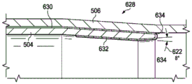
图13示出了根据本发明形成的组装的机械压力配合的管接头的横截面视图;和Figure 13 shows a cross-sectional view of an assembled mechanically press fit pipe joint formed in accordance with the present invention; and
图14示出了图13所示的机械压力配合的管接头的可替代实施例的横截面的细节图。FIG. 14 shows a detail view of a cross-section of an alternative embodiment of the mechanically press fit fitting shown in FIG. 13 .
具体实施方式Detailed ways
简介Introduction
在现有技术的发展中,公开了用于形成具有更均匀和一致性的机械压力配合的管接头的系统及相关装置和方法,借此克服了此前所提及的缺陷。数据采集、存储和分析可以被用于控制在组装之前形成管端部的过程以及机械压力配合的接头的组装过程本身。上述过程制造了优异的机械压力配合的接头并提供记录数据,以用于设置标准以及使得以跟踪管道条件和表现、探测故障和失效等为目的的管道完整性的监控成为可能。基础数据,例如:形成管端部和组装机械压力配合的接头所施加的压力,以及箱(或钟)端进入到形成的或连接的销(或锥)端的重叠部分的长度,可以被积累并将其用于管道记录、正在进行的分析和用于机械压力配合的管接头和通常的管道完整性的标准。以下机械压力配合的管接头可以被称为MPF接头,涉及由这里描述的装置和方法所连接的管段。MPF接头图示于图13中的附图标记620。In a development of the prior art, systems and related apparatus and methods for forming pipe joints with a more uniform and consistent mechanical press fit are disclosed, thereby overcoming the previously mentioned deficiencies. Data acquisition, storage and analysis can be used to control the process of forming the pipe ends prior to assembly as well as the assembly process itself of the mechanically press fit joint. The above process produces excellent mechanical press fit joints and provides recorded data for use in setting standards and enabling monitoring of pipeline integrity for purposes of tracking pipeline condition and performance, detecting faults and failures, and the like. Basic data, such as the pressure applied to form the pipe ends and assemble the mechanical press-fit joint, and the length of the overlap of the box (or bell) end into the formed or connected pin (or cone) end, can be accumulated and Use it for pipe documentation, ongoing analysis, and standards for pipe joints and general pipe integrity for mechanical press fits. The following mechanically press-fitted pipe joints may be referred to as MPF joints, referring to pipe segments connected by the apparatus and methods described herein. The MPF junction diagram is shown at
被积累的数据可以被发展为组装的机械压力配合接头的适合性的标准指数,以在监测组装、形成工业标准等方面使用。当管段端部制备期间所做的测量和组装MPF管接头落入独特的由被测量的组装数据和后续的在组装好的接头上执行的测试数据导出的指数范围内时,可以确保得到优异的接头。从积累的组装和测试数据中可以发展出用于不同尺寸、重量、壁厚、材料和等级的管的标准。通过读取用于使用这里公开的标记和记录系统的存储的数据和管道权限的能力,可以促进作为例行的定期检查或者以定位管道完整性偏差为目的管道的监测,以获得有关管道完整性的精确数据。可以理解的是,为了能够快速定位和诊断管道中的问题,以在小问题变成大问题之前发现小问题,监测和检查规则是至关重要的。The accumulated data can be developed into a standard index of suitability of assembled mechanical press fit joints for use in monitoring assembly, developing industry standards, and the like. Excellent results are assured when measurements made during pipe end preparation and assembled MPF fittings fall within a unique index range derived from the measured assembly data and subsequent test data performed on the assembled joint. connector. From accumulated assembly and test data, standards can be developed for pipes of different sizes, weights, wall thicknesses, materials and grades. The ability to read stored data and pipeline permissions for use with the tagging and logging system disclosed herein can facilitate monitoring of pipelines, either as a routine periodic inspection or for the purpose of locating pipeline integrity deviations, to obtain relevant information on pipeline integrity. precise data. Understandably, in order to be able to quickly locate and diagnose problems in the pipeline to catch small problems before they become big problems, monitoring and checking rules are critical.
将要描述的系统可以包括与编程的处理器和图像的用户界面耦合的多个输入数据采集装置,其中图像的用户界面可以通过特殊化的软件来控制以便在压力配合的管接头被组装时使得用户能够实时观看感兴趣的参数。这些功能单元可以被嵌入计算机中或者以单独的结构提供,统称为“计算机”。数据库可以与计算机或者系统耦合以用于积累数据。与数据采集输入端连接的传感器可以包括多个部件,例如感应为了迫使管段在一起所施加的压力P的部件,感应被连接的管端部的重叠或者形成的长度L的部件,以及用于指示尺寸或者温度条件的其它传感器。通过传感器可以将计算机与在管端部执行形成和组装操作的液压模锻(也被称为钢板锻造)机器相连。例如,压力测量可以是被机器施加的用于组装形成的端部以完成MPF接头的以lb./in2为单位的液压管路压力。长度测量可以是以英寸为单位的第一管段的箱端重叠与第一管段相连接的第二管段的销端的距离。该系统还可以于在模具上形成管箱端和销端的过程中被使用,该模具由位于将要被描述的适合的液压锻造机器的心轴所支撑。通过在这里将被描述的装置和方法,通过机器直接向心轴/模具组件施加的压力,以及沿着管端部的模具的横断面也可以被测量并记录。The system to be described may include a plurality of input data acquisition devices coupled with a programmed processor and a graphical user interface that can be controlled by specialized software to enable the user to Ability to view parameters of interest in real time. These functional units may be embedded in a computer or provided in a separate structure, collectively referred to as a "computer". A database can be coupled to a computer or system for accumulating data. The sensor connected to the data acquisition input may include a number of components, such as a component that senses the pressure P applied to force the pipe sections together, a component that senses the overlapping or formed length L of the pipe ends being connected, and a component for indicating other sensors for size or temperature conditions. The computer can be connected via sensors to a hydraulic die forging (also known as steel plate forging) machine that performs forming and assembling operations at the pipe ends. For example, the pressure measurement may be the hydraulic line pressure in lb./in2 applied by the machine to assemble the formed end to complete the MPF joint. The length measurement may be the distance in inches by which the box end of the first pipe section overlaps the pin end of the second pipe section connected to the first pipe section. The system can also be used in forming the box and pin ends on a die supported by a mandrel on a suitable hydraulic forging machine as will be described. With the apparatus and method to be described herein, the pressure applied by the machine directly to the mandrel/die assembly, as well as the cross-section of the die along the end of the tube, can also be measured and recorded.
在测量箱端的重叠或者行程长度L中,一种传感器类型被称为字符串编码器(或者字符串罐,拉线,或者yo-yo罐)。其它种类的长度传感器可以包括光学或者声学机制的传感器。无论是哪种用于测量和指示重叠长度的方法,都要建立基准或起始点,例如通过将箱的端部置于靠近销端部(在规定的公差之内,例如+1/4~0英寸)并将重叠长度测量设置为零。各种用于建立这种参考的技术是本领域公知的。在测量施加于液压机器以形成管端部或者将管端部组装到一起的压力时,压力P相似的设置为“低设置起始点”例如10psi,这是一个参考值或者起始条件值。In measuring the overlap or stroke length L at the end of the box, one sensor type is called a string encoder (or string can, pull wire, or yo-yo can). Other types of length sensors may include sensors of optical or acoustic mechanisms. Whichever method is used to measure and indicate overlap length, establish a datum or starting point, such as by placing the end of the box close to the end of the pin (within a specified tolerance, such as +1/4 to 0 inches) and set the overlap length measurement to zero. Various techniques for establishing such references are known in the art. When measuring the pressure applied to a hydraulic machine to form or assemble pipe ends together, the pressure P is similarly set to a "low set start point" such as 10 psi, which is a reference or starting condition value.
其它在系统中提供的用于计算机的设备可以包括用于连接键盘、GPS仪器的接口等的USB接口;用于视频或者其它基带信号输出(例如HDMI输出);通向数据库的数据链路以存储带有历史记录的数据;通过以太网或者其它网络接口标准的用于链路的连接,以及常规的电源连接,指示器等。计算机可以通过合适的通信链路与产品或者组装装置交互,并且可以包括用于操作产品或者组装装置的控制机制。这种机制可以包括软件、例如伺服机制,转换器,指示器和测量仪表等通向机器零件的链路,用于形成管端部的典型的机器零件包括液压锻造机器。形成模具在由机器的固定或移动部分支撑的心轴中得到支撑。除了以与锻造机器将管端部连接在一起相同的方式在液压下迫使两个相对的管端部到一起而不是在模具上对一个管段的端部施力以使其形成之外,组装机器与锻造机器非常相似。Other equipment provided in the system for the computer may include a USB interface for connecting a keyboard, an interface for a GPS instrument, etc.; for video or other baseband signal output (eg HDMI output); a data link to a database for storage Data with history; connections for links via Ethernet or other network interface standards, as well as regular power connections, indicators, etc. The computer may interact with the product or assembly through a suitable communication link, and may include control mechanisms for operating the product or assembly. Such mechanisms may include software, such as servo mechanisms, transducers, indicators and gauges, etc., links to machine parts, typical machine parts used to form pipe ends include hydraulic forging machines. The forming dies are supported in mandrels supported by stationary or moving parts of the machine. The assembling machine, except that the ends of one pipe section are formed by hydraulically forcing two opposing pipe ends together in the same way that a forging machine joins the pipe ends together, rather than forcing the end of one pipe section on the die to form it Very similar to forging machines.
这里还要公开的是新指数,其被发展以提供了易于观察并且可重复的箱端与销端的重叠的正确量的指示,以建立可接受的MPF管接头。该指数的目的是识别正确形成的MPF接头被形成的时刻。一个例子是将两个管端部挤压的液压P(lb/in2)乘以箱端越过销端的重叠长度L(in)。该结果具有单位lb/in,这是线性偏离的单位,并且可以与或者并不与迫使管的箱端或钟端于管的销端或锥端之上所需的力的大小相关。如将要描述的图7和图8所示,指示正确形成的机械压力配合的管接头的P和L的值的组合在P-L曲线中也是明显的。Also disclosed herein are new indices that were developed to provide an easy-to-see and repeatable indication of the correct amount of box end to pin end overlap to establish an acceptable MPF fitting. The purpose of this index is to identify the moment when a correctly formed MPF linker is formed. An example would be multiplying the hydraulic pressure P (lb/in2) of the extrusion of the two tube ends by the overlap length L (in) of the box end over the pin end. This result has units of lb/in, which is a unit of linear deviation, and may or may not be related to the amount of force required to force the box or bell end of the tube over the pin or cone end of the tube. The combination of the values of P and L indicating a properly formed mechanically press fit fitting is also evident in the P-L curve, as shown in Figures 7 and 8 to be described.
参数P代表形成一根管的端部或者将两个成形的管端部组装在一起所需的液压,参数L代表一段越过另一段的重叠长度或者在将管段端部形成箱端的过程中行进的距离,该参数P和参数L基于当以例如焊接或者螺纹的其它方法组装管段时的相似的重要参数。在两种连接管段的传统方法中,由将要重叠相对段的销端的箱端的尺寸表达的重叠长度L是关键参数。对于焊接接头,重叠长度L将取决于焊接类型、完成的接头的所要求的结构以及其它因素,例如管的尺寸和材料。对于螺纹接头,例如螺纹的类型和节距、在组装接头时是否使用了密封剂等与管的其它特征一起将决定参数L的选择。The parameter P represents the hydraulic pressure required to form the end of one tube or to assemble two formed tube ends together, and the parameter L represents the overlapping length of one section over another or the travel in the process of forming the end of the tube section into the box end The distance, the parameter P and the parameter L are based on similar important parameters when assembling pipe segments by other methods such as welding or threading. In the two conventional methods of connecting pipe segments, the overlap length L, expressed by the size of the box ends that will overlap the pin ends of the opposing segments, is the key parameter. For welded joints, the overlap length L will depend on the type of weld, the desired configuration of the finished joint, and other factors such as the size and material of the pipe. For threaded joints, such as the type and pitch of threads, whether a sealant was used when assembling the joint, etc., along with other characteristics of the pipe, will determine the choice of parameter L.
为了理解为何在测量机械压力配合的管接头的形成时参数是有用的,将管端部连接在一起的传统方法的例子可能是有帮助的。如在管道中使用的钢管是很重的组件,所以将带有螺纹的管段旋转到带有配合螺纹的相对的管段之上可能要求使用液压机器以提供必要的动力。随着第一段提升至第二段之上(或之中),在螺纹区域中的特定大小的摩擦必须通过液压予以克服以操作机器,该机器旋转第一段来抵抗由接触第二段产生的摩擦。随着接头接近完成,达到一个段的螺纹端部,从而使液压更快速地增加。这种情况表明接头接近于完全形成。事实上,特定的压力可作为充分开螺纹接头的有用测量。在达到这一压力之前,接头可能没有完成;超过压力P开始更快速增加的点为参考压力,如果超过这一压力可能导致螺纹剥离、劈裂管或者其它缺陷。可以期望的是,指示合适螺纹连接的压力位于上述两个值之间,并且可能会与重叠的长度L紧密相关。相似的,对于焊接接头,管的尺寸,特别是箱端和销端相接触的部分,例如接头的相接触的总表面积将与把管端部组装到一起所需的压力P和重叠长度L相关。To understand why parameters are useful in measuring the formation of mechanically press-fitted pipe joints, an example of a traditional method of joining pipe ends together may be helpful. Steel pipes such as those used in piping are heavy components, so rotating a threaded pipe section over an opposing pipe section with mating threads may require the use of a hydraulic machine to provide the necessary power. As the first segment is lifted over (or into) the second segment, a certain amount of friction in the threaded area must be overcome hydraulically to operate a machine that rotates the first segment against the resulting contact with the second segment friction. As the joint nears completion, the threaded end of a segment is reached, allowing hydraulic pressure to increase more rapidly. This condition indicates that the linker is nearly fully formed. In fact, a specific pressure can be a useful measure of an adequately threaded joint. The joint may not be complete until this pressure is reached; the point above which pressure P begins to increase more rapidly is the reference pressure, which may lead to thread stripping, splitting of the tube, or other defects if exceeded. It can be expected that the pressure indicative of a suitable threaded connection lies between the above two values and may be closely related to the length L of overlap. Similarly, for welded joints, the dimensions of the pipe, especially the parts of the box and pin ends that come into contact, such as the total surface area of the joint in contact, will be related to the pressure P and the overlap length L required to assemble the pipe ends together. .
将这两个变量P和L的效果可视化的一种方法是在直角坐标系中将一个变量相对于另一变量作图。随着重叠增加而压力增大,这将会产生具有正斜率的曲线。如果可接受的P和L值给定公差,例如+/-5%,那么由两个参数的最小和最大允许值定义的接受矩形可以叠加在图上并且能够在图上计算或者描述其面积。选择本示例中的公差是用于说明概念。正确的公差可以从实际使用中获得的经验数据中获得。将管端部连接在一起直到P-L曲线进入接受矩形中的装置的操作提供了正确组装接头的容易观察的指示器。进一步,测量值通过在图形显示器上的传感器输入到计算机并且还可以被储存以待后续使用。指数可以例如被称作“力配合数”,“PL乘积”,或者“压力配合乘积”。如果“PL乘积”位于图形显示器上的接受窗口内,这是因为压力P和长度L 的乘积与实质的且均匀的管的箱端和销端之间的金属到金属的接触相关。这仅是指数及其在帮助管内压力配合的机械接头的组装中的用途的一个例子。One way to visualize the effect of these two variables, P and L, is to plot one variable relative to the other in a rectangular coordinate system. As the overlap increases and the pressure increases, this will produce a curve with a positive slope. If the acceptable P and L values are given a tolerance, eg +/- 5%, then the acceptance rectangle defined by the minimum and maximum allowed values of the two parameters can be superimposed on the graph and its area can be calculated or described on the graph. The tolerances in this example were chosen to illustrate the concept. The correct tolerance can be obtained from empirical data obtained in actual use. The act of joining the tube ends together until the P-L curve enters the device in the receiving rectangle provides an easy-to-see indicator that the joint is properly assembled. Further, the measured values are input to the computer via sensors on the graphic display and can also be stored for subsequent use. The index may be referred to, for example, as a "force fit number", "PL product", or "press fit product". If the "PL product" is within the acceptance window on the graphical display, it is because the product of pressure P and length L is associated with substantial and uniform metal-to-metal contact between the box and pin ends of the tube. This is but one example of the index and its use in the assembly of mechanical joints to aid in a press fit within a pipe.
上述的指数可以与例如施工现场的温度的其它变量相关。对于众多施工现场,管的类型和尺寸和P,L值以及温度T的数据积累可以表明确保最可靠压力配合管接头的方法的变化。积累的数据可以被记录在表格中以协助用于组装管道的压力配合装置的安装,组装管道既用于构造新管道或者用于修复旧管道以使它们重新服役。因为温度不仅影响管材料的柔韧性,归因于扩张和收缩的尺寸变化,而且影响在压力配合装置中使用的液压流体的粘度,所以这些数据可以很重要。如果在接头中使用密封组合物或者环氧树脂或者其它胶粘材料,它们的性质也可能会被温度变化影响。总体而言,可以为代表涉及压力配合组装过程的参数的任意变量建立用于MPF接头的组装表格。The aforementioned indices may be related to other variables such as the temperature of the construction site. For numerous construction sites, the accumulation of data on pipe types and sizes and P, L values, and temperature T can indicate changes in methods to ensure the most reliable press fit pipe joints. The accumulated data can be recorded in tables to assist in the installation of press fit devices for assembled pipes, either for the construction of new pipes or for the repair of old pipes to bring them back into service. These data can be important because temperature affects not only the flexibility of the tube material, dimensional changes due to expansion and contraction, but also the viscosity of the hydraulic fluid used in the press fit device. If sealing compositions or epoxies or other adhesive materials are used in the joint, their properties may also be affected by temperature changes. In general, assembly tables for MPF joints can be built for arbitrary variables representing parameters involved in the press fit assembly process.
有资格的用户或订阅者,管道权威部门,管生产者,管道承包商及类似人员可以读取到如此积累的数据。数据可以作为历史数据查阅或者实时观察。数据可能与特定的生产将要被安装的管道的生产商或者工厂相关。通过互联网或其它网络可以容易地提供对于数据的访问。The data thus accumulated can be read by qualified users or subscribers, pipe authorities, pipe producers, pipe contractors and the like. Data can be viewed as historical data or observed in real time. The data may be associated with a particular manufacturer or factory producing the pipe to be installed. Access to the data can be readily provided through the Internet or other networks.
压力配合装置的描述Description of the press fit device
用在此处描述的系统和过程中使用的压力配合装置包括两个液压装置。它们外观相似,但是为实现它们特定的功能而进行不同的配置。每一个液压装置可以被认为是工作台或者框架,其配备有轨道,液压操作的夹子或工件沿着轨道安装。在“端部制备”机器中,滑动件可以在与液压源相连的工作台的端部安装于轨道上。滑动件支持用于形成管箱端或者是销端的工具(由心轴支持的模具)。在管道的相对端部,用于安全的保持将要被形成的管段的管夹组合体可以沿着与模具相同的纵轴被固定于轨道。在由液压泵向可移动杆提供的液压的作用下,可以迫使或者驱动可移动的模具移向固定的管段。液压泵可以由内燃机驱动,典型地柴油发动机。端部制备机器典型地可以被用于方便形成管段的箱端和销端的场所。场所可以位于也可以不位于管道被构造的场所。The press fit device used in the system and process described here includes two hydraulic devices. They look similar, but are configured differently for their specific functions. Each hydraulic device can be thought of as a table or frame, which is equipped with rails along which hydraulically operated clamps or workpieces are mounted. In "end preparation" machines, slides may be mounted on rails at the end of a table connected to a hydraulic source. The slide supports the tool (die supported by the mandrel) used to form the box end or pin end. At the opposite end of the pipe, a pipe clamp assembly for safely holding the pipe section to be formed can be secured to the rail along the same longitudinal axis as the mold. The movable die can be forced or driven towards the stationary pipe section under the action of hydraulic pressure provided by the hydraulic pump to the movable rod. The hydraulic pump may be driven by an internal combustion engine, typically a diesel engine. End preparation machines can typically be used in locations that facilitate the formation of box and pin ends of pipe sections. The site may or may not be located at the site where the duct is constructed.
夹紧部分可以具有液压操作的半球形夹爪,该夹爪在一端连接于沿着半径隔开的刚好超出半球形部分的枢轴,以此夹爪可以被置于将要被夹住的管的周围并且通过液压被拉到一起以将管道夹紧就位。夹爪的开口端可以沿着液压油缸耦合到一起,以使得夹爪可以被打开和关闭。半球形的夹爪可以与模具相配合以适应将被连接的管的特定直径。The gripping portion may have a hydraulically operated hemispherical jaw connected at one end to a pivot shaft spaced along the radius just beyond the hemispherical portion, whereby the jaw may be placed in the position of the pipe to be gripped. around and hydraulically pulled together to clamp the pipe in place. The open ends of the jaws can be coupled together along the hydraulic ram so that the jaws can be opened and closed. The hemispherical jaws can be fitted with the die to accommodate the specific diameter of the pipes to be connected.
在与液压操作的锻造机器装置相似的“现场组装”机器中,在工作台或者框架上的轨道支撑两个相对的夹紧部分,其可用于支撑待连接的管端部。其中一个管夹可以被固定于轨道,而另一个可以被配置为在液压的作用下沿着轨道滑动至固定在滑动夹的缸体。在端部制备机器中,轨道确保至少一个夹紧部分能够向着其它夹紧部分移动并且远离其它夹紧部分移动并同时维持它们之间的固定的轴向关系,以此确保待连接的管端部被正确对准。相同类型的枢轴夹爪夹紧部分可以被用来固定用于连接的管端部。在管道现场的使用中,组装机器可以由安装于交通车辆上的侧面起重机支撑。用于操作现场组装机器的液压泵可以由例如柴油发动机的内燃机驱动。车辆因此可以沿着现场的侧面移动以将组装机器安置在每一对将要被组装的管端部的位置。In "assemble-in-place" machines similar to hydraulically operated forging machines, rails on a table or frame support two opposing clamping sections, which can be used to support the pipe ends to be joined. One of the pipe clamps may be secured to the rail, and the other may be configured to slide hydraulically along the rail to a cylinder secured to the slide clamp. In an end preparation machine, the rail ensures that at least one gripping part can move towards and away from the other gripping parts while maintaining a fixed axial relationship between them, thereby ensuring that the pipe ends to be connected is correctly aligned. The same type of pivot jaw gripping portion can be used to secure the pipe ends for connection. In use at the pipeline site, the assembly machine may be supported by a side crane mounted on a traffic vehicle. Hydraulic pumps used to operate field-assembled machines may be driven by internal combustion engines such as diesel engines. The vehicle can thus be moved along the side of the site to position the assembly machine in the position of each pair of pipe ends to be assembled.
端部制备和现场组装机器优选地可以与计算机监测系统耦合(“CMS”或者“计算机”)以测量MPF接头操作中涉及的某些选定的参数,包括或者是用于连接的管端部的制备或者是在现场将制备好的端部的组装。作为过程监测子系统24一部分的CMS可以优选地被编程用于处理由适当的传感器提供的测量数据,用于将数据转换为可以在显示屏上以图形方式显示的形式,用于在数据库中存储数据及其处理过的形式(“数据产品”),以及用于通过网络将数据和数据产品通信至外部位置以便数据和过程管理,以及其它类似用途。The end preparation and field assembly machine can preferably be coupled with a computer monitoring system ("CMS" or "computer") to measure certain selected parameters involved in the operation of MPF joints, including or for the pipe ends being joined. Preparation or assembly of the prepared ends on site. The CMS, which is part of the
用于操作端部制备机器和现场组装机器的系统也包括与CMS输入端耦合的数据采集单元,用于接收参数传感器的输出并将这些信号转化为数字形式以供计算机监控系统处理。传感器优选地可以是用于测量由操作端部制备机器和现场组装机器的液压油缸提供的液压管路压力P的传感器,以及用于测量行程长度L的线性位移传感器,行程长度L对于提供一段管的箱端越过管的相邻段的销端的正确的重叠量是必要的。线性量规传感器的例子包括“字符串电位计”(或者“字符串罐”或者“yo-yo罐”),以及激光位移计,这些都是本领域熟知的技术。控制CMS的操作程序可以被存储在计算机监控系统中的非易失性存储器中。The system for operating end preparation machines and field assembly machines also includes a data acquisition unit coupled to the input of the CMS for receiving the outputs of the parametric sensors and converting these signals into digital form for processing by the computer monitoring system. The sensors may preferably be sensors for measuring hydraulic line pressure P provided by hydraulic rams operating end preparation machines and field assembly machines, and linear displacement sensors for measuring stroke length L, which is necessary to provide a length of pipe. The correct amount of overlap of the pin end of the box end over the adjacent section of tube is necessary. Examples of linear gauge sensors include "string potentiometers" (or "string pots" or "yo-yo pots"), and laser displacement meters, all of which are well known in the art. The operating program to control the CMS can be stored in non-volatile memory in the computer monitoring system.
耦合到计算机的图形显示屏优选地被用于显示由CMS生成的参数或数据产品的图形。主要感兴趣的是用于将夹持管端的可移动管夹向其相对构件推进的液压压力P(上述构件是端部制备机器的形成模具或工具或者是夹持将被连接的其它管段的端部的管夹),与在形成机械压力配合接头过程中产生的重叠行程长度L的曲线。压力P相对于长度L作图,P沿着纵轴,L沿着横轴。随着重叠长度的增加压力也增加,所得到的曲线通常具有正的斜率。曲线的斜率和形状可能包含有关已形成的接头状态或者被监控机器的操作状态的信息。这些信息在测量接头质量及其寿命方面非常有用,在诊断管或者连接过程中的异常情况方面也是有用的。进一步,随着用于后续分析和创建历史纪录的数据被存储,可以了解很多有关管材料,及其生产和组装中使用的方法,未来数年有关管道和管道接头完整性的内容。特别是历史数据将有助于在现场开发更好的连接管段的方法。A graphical display screen coupled to the computer is preferably used to display graphics of the parameters or data products generated by the CMS. Of primary interest is the hydraulic pressure P used to push the movable clamp holding the pipe end towards its opposing member (the said member being the forming die or tool of the end preparation machine or the end holding the other pipe sections to be connected). pipe clamp), and the curve of the overlapping stroke length L created during the formation of the mechanical press fit joint. Pressure P is plotted against length L, with P along the vertical axis and L along the horizontal axis. As the overlap length increases, the pressure also increases, and the resulting curve typically has a positive slope. The slope and shape of the curve may contain information about the state of the joint that has been formed or the operating state of the machine being monitored. This information is very useful in measuring joint quality and its life, and in diagnosing anomalies in the pipe or connection process. Further, as data is stored for subsequent analysis and creation of historical records, much can be learned about the pipe material, and the methods used in its production and assembly, about the integrity of pipes and pipe joints for years to come. In particular, historical data will help develop better methods of connecting pipe segments in the field.
系统的详细描述Detailed description of the system
在之后的描述中,在多幅图中出现的附图标记指代相同的结构。图1示出了本发明一个实施例的系统框图。该实施例描绘了系统10的主要部件或者子系统,系统10在生产环境中接收原始管60,处理管以便将其准备好以用于组装成使用机械压力配合的管接头形成的防泄漏管道。在提供内置的用于测量和积累在生产、安装以及监控过程中产生的用于分析、维护、管理以及发展管道标准的数据的同时,系统10还提供组装管以构造管道。由于是本领域公知的且没有构成本发明的一部分,图1没有示出各种输送和存储设备,其可能(取决于特定环境)在通过示于图1的一系列子系统参与输送。In the following description, reference numerals appearing in several figures refer to the same structures. FIG. 1 shows a system block diagram of an embodiment of the present invention. This embodiment depicts the major components or sub-systems of a
系统10包括一系列主要功能的子系统,开始于设备12,其用于接收标准原始管段60(典型地,每根长40英尺)以经受通过使用机械压力配合的接头待组装为管道的管段60的端部制备过程。这里指出的机械压力配合的管接头是在压力作用下通过力作用而结合到一起,并且不需要焊接或者在管的端部加工螺纹以在管安装位置以端对端的方式将管段连接在一起。下一个子系统包括用于形成作为机械压力配合的接头而将待连接在一起的管端部的设备14。设备14可以包括由操作器(液压机器控制器22)控制的液压泵驱动的机器装置,其中该过程由过程监控计算机24监控,用于接收传感器数据并在显示器 26上以图像形式显示一些制备步骤的参数。机器设备14支撑着用模具纵向对准地正在形成的管端部,随着模具在液压下通过力的作用越过管端部。The
在管段端部的一端形成箱(或钟)端,并在子系统14的相对端形成销 (或锥)端,管段准备好在施工现场组装成管道,如子系统16所示。管段的组装包括由控制器(液压机控制器22)控制的液压泵驱动的机器设备,其过程由过程监控计算机24监控,用于在显示器26上以图像形式显示一些组装步骤的参数。子系统16中的机器设备,其可以是适于操作管段的锻造机器,其纵向对准地支撑着管段随着管段在液压下被压在一起。A box (or bell) end is formed at one end of the end of the pipe segment, and a pin (or cone) end is formed at the opposite end of the
在管端部的形成和管段的组装期间,包含用于监测组装管道的完整性的传感器和电路的装置可以安装在管段上。应用在子系统18中的完整性监控电路在管道构造完成之后连续地测量管道的各种条件,以提供管道的维护和安全以及有效的操作。子系统18中生成的数据可以优选地被转发到管道数据采集站20。During formation of the pipe ends and assembly of the pipe sections, a device containing sensors and circuitry for monitoring the integrity of the assembled pipe may be installed on the pipe sections. Integrity monitoring circuitry implemented in
系统的其他部件包括液压机器控制器22,其耦合到每个机器设备成形机 14和机器设备组装机16。在典型的实施例中,这些可以是用于测量所选择的控制参数的手动控制和适当的传感器23(如将被描述的)。过程监控计算机 24可以耦合到机器控制子系统22、23,用于接收传感器数据并对其进行响应。连接到过程监控计算机24的显示器26提供控制参数的可觉的图形表示。用于控制包括液压P和行程长度L的图形显示的过程监控计算机24的操作的过程程序可以存储在非易失性程序存储器中。过程监控计算机24还可以包括用于耦合到网络36的通信接口。管道数据采集子系统20还优选地包括耦合到网络36的通信接口。网络36使子系统20和24能够和数据管理中心计算机 40(也称为“DMC 40”)进行数据通信,用于归档和处理关于管段和完成的管道的制备、组装和监控的数据。提供数据库42和显示器44以帮助子系统40 的归档和处理功能。Other components of the system include the
DMC 40计算机可以是具有多个计算机、服务器等的系统,其根据需要执行分配给它的从事收集、分析和其他处理发送到DMC 40的数据的功能的。这些和其他功能可以由为管理这些功能而开发的适当的软件提供。应用软件套件38可以包括至少一个操作程序,用于处理源自数据采集系统的关于管道操作参数和条件的数据测量,例如在端部制备和现场组装操作期间获取的液压P和行程长度L。数据管理中心计算机40可以进一步在数据管理系统中被使用,该数据管理系统响应于通过耦合到已安装的管道的设备监控管道数据期间获得的数据。传送到数据管理中心计算机40的数据可以被应用软件套件 38的组件进行处理,该应用软件套件38可以从数据管理中心计算机40访问。应用软件套件38包括必要的存储设备,其可以直接耦合到数据管理中心计算机40,或者可通过网络访问到远程存储设备,如本领域所熟知的。通过这样的装置(将在图9和图10中描述)获得的数据可以被处理并转发到数据管理中心计算机40,以在为这些目的选择或开发的应用软件套件38的控制下执行如上所述的服务以及对管道运营商和其他负责管道安全及管道的高效运行的实体的管理、故障排除和全面管理活动。The
图2示出了管过程系统50,其针对用于图1的系统中的管进行处理。该图稍微扩展了子系统22和24的组件。过程监控计算机24包括多个功能部分: CPU、程序和数据存储器(包括非易失性存储器)以及数据采集、I/O、显示处理、GPS(全球定位卫星)接收器以及通信接口(包括以太网)。键盘27 和鼠标29以及GPS天线可以连接到计算机24的相应的I/O和GPS接收器端口。以太网端口可以与卫星链路或其他通信提供商耦合。数据采集输入端可以优选地连接到耦合到液压机器22的传感器的输出端,以提供用于液压、长度计、环境温度以及液压流体温度的信号。FIG. 2 shows a
液压机器22通常由液压动力单元30驱动,例如配备有歧管的柴油动力泵(未示出)、流体管线和阀,以在压力下控制流体流动到机器上的致动器。液压机器可以由操作者使用手动控制单元32操作,同时观察在形成或组装机械管接头时以图形方式显示操作参数的显示器26。结合到图2的系统中的一个特征是排放阀34,其可以手动地或自动地操作以将液压流体的高压流转向与液压泵系统相关联的蓄水池(未示出),以响应于在图形显示器上观察到的异常操作的液压。该动作停止液压机器的操作,以允许操作者考虑到工件(管) 触发排放阀操作的情况。排放阀34在液压进给管线中耦合到液压机器。例如,如果压力过大,排放阀34可以自动操作;相反,如果液压不足,操作人员可以手动地触发排放阀34。可以为排放阀34的操作建立其他条件。The
图3示出了在图1和图2的实施例中使用的管端部制备机器70的一个实施例的俯视图。由底座72支撑的端部制备机器70被构造成用来形成管段的箱端和销端,使得管段可以端对端地组装以形成管道,如图13将要描述的。在导轨84上行进的滑动件80(包括心轴)由液压缸74驱动,液压缸74使驱动杆76沿着导轨84推进滑动件80。滑动件80能够沿着导轨84滑动一段距离,该距离适当地超过在端部制备过程中完全形成管段的箱端504或销端部506(参见图13)所需的行程长度。滑动件80支撑心轴中的模具82(参见图 11)。模具可以是如图11和图12所示的箱端模具600或销端模具610。滑动件80将模具82推向支撑于管夹90中的相对的管端60,管夹90固定在端部制备机器70的底座72。管端60被夹紧在管夹90的夹爪中。通过液压缸92 使管夹的夹爪移动关闭或打开。FIG. 3 shows a top view of one embodiment of a pipe
继续图3,以形成管端的滑动件的位移或行程长度的测量可以使用几种装置中的任何一种,位移测量装置选自由字符串电位计、测量带和激光测距仪组成的群组。在实施例中,字符串罐110可以固定到管夹90上,用于测量模具82完全形成管端60所需的行程长度L。作为可伸缩地存储在字符串罐110 中的一段线路的字符串计量器114,可以在该示例中在其远端处固定到附接到滑动件80的连接点116。当滑动件80从预定的基准(“零”)位置移动时,字符串罐110测量当模具82从零基准L=Lo前进时缩回的字符串计量器114的量,以与管端60重叠一个指定量L=Lf以在L=Lf处形成完全完成的机械压力配合的接头。由字符串罐110传感并被转换成长度单位(例如,英寸“in”) 的字符串计量器的量等于管端的形成时在图形显示中显示并被操作者观察的长度L。由字符串罐110传感的长度测量通过线路118耦合到过程监控计算机 24的数据采集输入端。在其他实施例中,字符串罐110可以被安装用来随着字符串计量器向外反馈而测量L的值。Continuing with Figure 3, the displacement or stroke length measurement of the slide to form the tube end can use any of several devices selected from the group consisting of string potentiometers, measuring tapes and laser rangefinders. In an embodiment, the
用于操作端部制备机器的液压可以在手动控制器32的控制下,通过管线 39由柴油动力液压动力装置30供给。根据用于驱动滑动件80的(多个)液压缸的结构,管线39可以是多条线路。管线39连接到通过由控制器32控制的阀102从液压动力单元30在高压下供应液压流体的连接件100的输出端。压力的量(例如Ib./in2(“Psi”))被换能器104传感,换能器104通过管线108 耦合到过程监控计算机24的数据采集部分的输入端。该换能器提供对应于下面将要描述的液压P的传感器信号。当需要中断流向控制滑动件前进的液压缸的液压流体的流动时,例如当压力P超过安全值时,连接件100包括排放阀34通过来自过程监控计算机24的管线106被控制。排放阀34也可以由操作者手动操作(出于为了清楚未示出机构,但在本领域中是众所周知的)。Hydraulic pressure for operating the end preparation machine may be supplied by a diesel powered
图4示出了用于图1和图2的实施例的管组装机器的一个实施例的俯视示意图。由基座132支撑的组装机器70被构造成用来在第一管段和第二管段之间形成一个机械压力配合的管接头以形成管道,如图13所示。在该示例中,第一管段120的箱端122被夹紧在固定到基座132的管夹150的夹爪中。第二管段126的销端124被夹紧在滑动管夹160的夹爪中。固定管夹150由液压缸134操作。滑动管夹160由液压缸136操作。当滑动管夹160通过液压缸140被拉向固定的管夹150时,滑动管夹160沿着一对轨道138行进。液压缸140由连接到连接件100的液压管线41驱动。类似地,用于操作管夹150、 160的液压缸134、136通过管线43由液压动力单元30供给液压流体。FIG. 4 shows a schematic top view of one embodiment of a tube assembly machine for use with the embodiments of FIGS. 1 and 2 . The
图4的其余结构在结构和功能上与图3的各个部件相同。The remaining structure of FIG. 4 is identical in structure and function to the various components of FIG. 3 .
机械压力配合过程的描述Description of the Mechanical Press Fitting Process
图5A和5B示出了针对制备用于组装以构造管道的管的箱端和销端的过程的流程图的一个实施例。初始步骤称为“预处理”,包括清洗和机加工,旨在调整管表面并在管端部的表面提供均匀的表面处理,以确保安全且液密封的机械接头,即没有孔洞和“假期”(间隙)、划痕和会破坏连接表面间的金属对金属的紧密接触的粗糙表面。这些预处理步骤可以包括施加某些润滑剂和防腐蚀剂以帮助预处理过程形成一致的、均匀的、成品表面,以最小化“假期”(管表面的间隙,划痕,孔洞等)、防止腐蚀以及保护表面免受损坏。目标是双重的:(a)确保安全的和防泄漏的接头;和(b)确保在制备和组装机械压力配合的管接头期间和之后进行的测量的可重复性。5A and 5B illustrate one embodiment of a flow diagram for a process for preparing box and pin ends of pipes for assembly to construct pipes. The initial steps, called "pre-treatment", include cleaning and machining, and are designed to condition the surface of the tube and provide a uniform finish on the surface of the tube ends to ensure a safe and liquid-tight mechanical joint, i.e., free of holes and "holidays" (gap), scratches, and rough surfaces that can disrupt the metal-to-metal contact between the joining surfaces. These pretreatment steps may include the application of certain lubricants and corrosion inhibitors to help the pretreatment process create a consistent, uniform, finished surface to minimize "holidays" (gaps, scratches, holes, etc. on the pipe surface), prevent corrosion As well as protecting the surface from damage. The goals are twofold: (a) to ensure a safe and leak-proof joint; and (b) to ensure repeatability of measurements made during and after the preparation and assembly of a mechanically press-fit fitting.
图5A的预处理步骤还可以包括喷砂或珩磨(或替代地钢丝刷清洗)以去除腐蚀(并提供裸露的金属或“白色金属”表面)以及使用某些工具,例如切割或研磨工具,从而将管段切割或研磨成特定的轮廓,并且用于加工或平滑表面以为施加某些物质以清洗或制备用于制造接头的连接表面做准备。如本领域所熟知的那样,珩磨和钢丝刷清洗的操作可以包括使用珩磨或切削油来帮助操作,延长珩磨工具的使用寿命(如果使用的话),并冲洗从清洁的表面通过操作去除的碎屑。所需的表面光洁度在“平均粗糙度”Ra为1至3mil (即0.001至0.003英寸)的范围内。Ra定义为高于平均值的峰值粗糙度变化的平均值。相似的测量参数可以表示为表面轮廓中峰值偏差的RMS或均方根值。The pretreatment step of Figure 5A may also include sandblasting or honing (or alternatively wire brushing) to remove corrosion (and provide a bare metal or "white metal" surface) and the use of certain tools, such as cutting or grinding tools, to thereby Pipe sections are cut or ground to a specific profile and used to machine or smooth surfaces in preparation for the application of certain substances to clean or prepare connecting surfaces for making joints. As is well known in the art, the operation of honing and wire brush cleaning can include the use of honing or cutting oils to aid the operation, prolong the life of the honing tool (if used), and flush the debris removed by the operation from the cleaned surface . The desired surface finish is in the range of "average roughness" Ra of 1 to 3 mil (ie, 0.001 to 0.003 inches). Ra is defined as the mean value of the peak roughness variation above the mean value. Similar measurement parameters can be expressed as the RMS or root mean square value of the peak deviation in the surface profile.
在清洗操作之后,可以优选使用防腐蚀剂。可以使用两种类型的防腐蚀剂;一种是溶剂基防腐蚀剂,另一种是矿物油基防腐蚀剂。每种可以被选择以适合管段和随后的工艺步骤、环境条件等一组特定的条件。例如,尽管溶剂型防腐蚀剂在涂覆或其它操作之前不需要额外的步骤来除去防腐蚀剂,油基防腐蚀剂通常需要在锻造机器(在如下述使用图3和图4所示的机器)操作中的端部形成过程之前进行清洗液体的轻微喷涂。防腐蚀剂也可以具有“脱水”属性,即脱水作为延缓“白色金属”表面的新腐蚀过程的手段的能力。After the cleaning operation, a corrosion inhibitor can preferably be used. Two types of corrosion inhibitors can be used; one is a solvent based corrosion inhibitor and the other is a mineral oil based corrosion inhibitor. Each can be selected to suit a specific set of conditions for the pipe section and subsequent process steps, environmental conditions, etc. For example, while solvent-based corrosion inhibitors do not require additional steps to remove the corrosion inhibitor prior to coating or other operations, oil-based corrosion inhibitors are typically required to operate in a forging machine (as described below using the machines shown in Figures 3 and 4). A light spray of cleaning liquid is performed before the end forming process. Corrosion inhibitors can also have "dehydration" properties, ie the ability to dehydrate as a means of retarding new corrosion processes on "white metal" surfaces.
从图5A开始,流程开始于步骤200并前进到步骤202,以开始用于制备待连接的管端部的预处理过程。步骤202可以包括将原料管传送和分类到检查位置。接下来,步骤204包括对待制备的端部的目视检查,随后是步骤206,用于在步骤208中选择用于机器倾斜操作的管段的销端。机器倾斜操作将在管的销端的边缘产生向外的斜面轮廓626(“斜面626”)。斜面量通常设置为相对于管段的纵向轴线成大约为8度并可以沿着管段的销端的内表面延伸大约1.00英寸。这些数字通常是标称中等管尺寸(例如,外径在6至8英寸范围内),对于较小或较大外径的管,可能需要调整该斜面轮廓的值,斜面626 提供了锥形,其在管端部的边缘稍微扩大了管的销端的内径,使得当销端在箱端内配合时,使得形成的MPF接头的内边缘对于组装的管道内的流体的流动呈现最小的阻碍。施加到销端的内表面的斜面或锥形626沿着销端的内表面延伸一段短距离,也形成机械管接头的“双锥形”构造的一半。具有销端的外径的第一锥形和沿内端的短部的第二锥形的构造近似于在管内部和外部均为平滑的无缝接头。参见图12和13。Beginning with Figure 5A, the flow begins at
进一步考虑图5A的流程图,然后将箱端和销端都传递到清洗步骤210,其可以包括使用润滑剂来珩磨和刚毛刷端部的表面,该润滑剂例如掺杂有高负载润滑剂(“HLBL”)的珩磨油,主要用于延长珩磨工具的使用寿命。清洗过程之后可以施加溶剂基或矿物油基防腐蚀剂,以及工业中众所周知的保护涂层或密封剂。在接下来的步骤212中,完全制备好的管段可以装载到端部制备机器70(参见图3)中以形成箱端或销端。下面从步骤306开始的图6A至6C的描述中进一步描述步骤212的形成箱端和销端的过程。当管段被固定到管夹90中,并且箱端模具600或销端模具610(分别参见图11和12)被固定在端部制备机器70的滑动件中,用于启动箱端504或销端506的形成的参考点或基准83可以在步骤214中被建立。在基准83被设置后(如下面段落所述),可以施加液压以激活端部制备机器70,并且可以测量液压P和完全形成箱端600或销端610的行程长度L。这些测量对于验证形成正确的管端部是至关重要的,并且被记录、绘制在图形400上(参见图7),以供端部制备机器70的操作者查看。Further considering the flow chart of FIG. 5A, both the box end and the pin end are then passed to a cleaning step 210, which may include honing and bristle brush end surfaces with a lubricant, such as doped with a high load lubricant ( "HLBL") honing oil, mainly used to prolong the service life of honing tools. The cleaning process can be followed by applying solvent-based or mineral oil-based corrosion inhibitors, as well as protective coatings or sealants well known in the industry. In the next step 212, the fully prepared pipe section may be loaded into the end preparation machine 70 (see Figure 3) to form the box end or pin end. The process of forming the box end and pin end of step 212 is further described below in the description of FIGS. 6A-6C beginning at
设置P和L的基准可以按照如下步骤完成。一旦管段60被固定在管夹 90内,计量字符串114的自由端从字符串罐110延伸(在这个示例中字符串罐110安装在固定管夹上)并附接到安装在用于支撑心轴82中的箱端模具600 或者销端模具610的滑动件80上的标杆116上。滑动件80沿着轨道84前进,直到模具600或610在管端部的预定距离内。该距离可以在零到1/4英寸之间变化,例如,使得在L=L0时可以将字符串罐设置为读取零英寸。从该基准点开始,如图3所示,当L=Lf时,该长度L被认为是达到目标长度。如图 1和图2所示,Lf的值可以被输入到数据库中累积的数据记录中。Setting the benchmarks for P and L can be done as follows. Once the
可以回想到,传统指示箱端应该与销端重叠的距离的方法是通过使用粉笔或其他容易看到的标记在销端端上通常用手来刻划。然后,当箱端通过力的作用越过销端时,施加外力直到箱端的端部到达销端上的标记。显然,这种操作取决于施加外力到箱端的机器的操作者熟练的眼手协调,以及设备的其他操作条件等。本质上是将管端部连接在一起的不可靠的方法,部分原因是不确定的重复性。此外,在传统方法中,没有创建距离(箱端在相邻销端上的重叠量)的记录,也不是长度标准化的值或用于对正在进行的过程的特定管段验证其准确度或确保其重复性的任何过程的值。这种缺乏验证或重复性信息会损害确定机械管接头失效原因的能力,因为没有数据追溯特定管接头的历史。没有关于如何准备和组装管接头的充分的数据,没有可靠的方式来证明管道已经被正确组装并且将能够承受在管道的寿命期间将经受的操作、环境和地质条件。It will be recalled that the traditional method of indicating how far the box end should overlap the pin end is by using chalk or other easily visible markings on the pin end, usually by hand. Then, as the box end passes over the pin end by force, an external force is applied until the end of the box end reaches the marking on the pin end. Obviously, this operation depends on the skilled eye-hand coordination of the operator of the machine applying the external force to the end of the box, as well as other operating conditions of the equipment, etc. Essentially an unreliable method of joining tube ends together, in part due to indeterminate repeatability. Furthermore, in traditional methods, no record of distance (the amount of overlap of box ends on adjacent pin ends) is created, nor is it a value normalized to length or used to verify its accuracy or ensure its The value of repeatability for any process. This lack of validated or reproducible information compromises the ability to determine the cause of mechanical fitting failure because there is no data to trace the history of a particular fitting. Without sufficient data on how to prepare and assemble pipe joints, there is no reliable way to demonstrate that the pipe has been assembled correctly and will be able to withstand the operational, environmental and geological conditions that will be experienced during the life of the pipe.
在本发明中,从销端的端部到“标记”的距离被定义为上述的Lf的值。因此,在操作中,在基准L=L0处,液压可以优选地设定为其初始值,例如 P=P0=10psi作为示例。将P和L的值设定为其初始值时,液压可以逐渐增加使得安装在心轴82中的模具600,610前进到要形成的管的端部。因为销端的外径有意地稍大于箱端的内径,因而建立了过盈接触,并且遇到相当大的摩擦阻力。该阻力对抗液压的增加,使得相对于完全形成管接头所需的行程长度L,压力P的上升绘制在曲线400中(参见图7)。完全形成的管接头通常将具有在图8所示的接受范围460内的Pf和Lf值。In the present invention, the distance from the end of the pin end to the "mark" is defined as the value of Lf described above. Thus, in operation, at reference L=L0, the hydraulic pressure may preferably be set to its initial value, eg P=P0=10 psi as an example. When the values of P and L are set to their initial values, the hydraulic pressure can be gradually increased so that the dies 600, 610 installed in the
返回到图5A,在步骤214之后,流程前进到步骤216,其中当P和L的正确值落在如图8所示的由参数P和L的最大值和最小值形成的接受窗口内时,操作者停止机器。如这数值定义了如将要描述的指示如图13所示的完全形成的和规格中的机械压力配合的管接头620的接受范围或接受窗口460。然后管段可以从机器上移走并且在步骤218中进行检查。如果管端部没有通过检查,则流程进行到步骤220以考虑是否废弃该管段或将其返回到步骤200以进行再处理。如果管段通过检查,则流程可以进行通过步骤222,其提供永久标签用于标记管段,使得单个管段在监控期间可以被追踪,并且可以数据积累可以被检索并存储在数据库中供以后分析。Returning to Figure 5A, after
标记步骤222可以通过多种方法来实现。所示示例的优选方法是将金属表面中的数字代码或序列号(包括某些特定数据)以字母数字形式表示或编码为条形码(优选二维条码)进行蚀刻,铭刻或印记。通过点喷丸过程施加的一种示例性的二维数据矩阵条形码可从Mecco Partners,LLC,Cranberry Township,PA 16066读取。这些代码可以由工业条形码阅读器读取,例如可以从Cognex Corporation,Natick,MA 01760读取。编码的数据可以包括制造工厂的位置、形成管端部的日期和时间、端部类型(箱或销),Mil规格数据等。该数据可以结合在为每个管段建立的数据记录中在端部制备形成过程中获得的P和L数据。数据记录可以进一步由管道现场处的组装数据补充,其中参数P和L再次被测量并存储在数据记录中,如在此将要描述的。The marking
在步骤222之后提供决定步骤224,以确定管段60是否必须被涂覆或必须安装监控总线导管,或者是否要在步骤226将其传送至存储或者准备运输。如果管段将要涂覆,例如为了防腐蚀,在图5B的步骤240进入另一个决定点,以决定是否将监控总线安装在管段上作为施加涂层的过程的一部分。监控总线可以是优选地在每个端部配备有连接器的电缆(也称为导管),以附接到管段的外表面,用于连接传感器元件和用于监控管道状态的其它电路,如将要在图9和图10中描述的。A
在继续如图5A和5B所示的制备用于组装的管端部的过程之前,有三个替代的可以包括在管段连接在一起之前涂覆管段的过程步骤。待描述的涂覆步骤可以在以下过程中多次进行。这些步骤可以包括内部涂覆或外部涂覆或者同时内部和外部涂覆,主要作为防腐蚀剂。通常,该过程可以包括施加基于溶剂基或矿物油基的防腐蚀剂的涂层。可替代地,该方法可以包括在管的表面上喷涂底漆,然后将液体环氧树脂的涂层喷涂到底漆表面上。Before continuing with the process of preparing the pipe ends for assembly as shown in Figures 5A and 5B, there are three alternative process steps that may include coating the pipe sections before they are joined together. The coating step to be described can be performed multiple times in the following process. These steps may include internal or external coating or both, primarily as corrosion inhibitors. Typically, the process may include applying a coating based on a solvent-based or mineral oil-based corrosion inhibitor. Alternatively, the method may include spraying a primer on the surface of the tube and then spraying a coating of liquid epoxy onto the primer surface.
在管中的管的外表面上没有安装监控总线,只有管的内表面通常被涂覆。如果要安装监控总线,管段将接受外部涂覆作为安装监控总线过程的一部分。在其他实例中,内部涂覆和外部涂覆都需要。因此,图5B概述了用于涂覆管段的过程步骤,包括如果需要安装监控总线。在图5A中的决定步骤224之后,流程前进到步骤240以判定是否要安装监控总线。如果判定为是,则流程进行到步骤242以确定管段是否仅接受外部涂覆。如果为判定为否,则过程进入步骤244以根据适用的规范进行内部涂覆过程。在涂覆了涂层的管段(或段)被检查后,如果通过检查流程进行到步骤248,以安装监控总线在管段上,通过将监控总线附接到管段的外表面。如果涂覆管段没有通过检查,则在处理步骤268中被转移到废料或返工操作以待处置。No monitoring bus is installed on the outer surface of the tube-in-tube, only the inner surface of the tube is usually coated. If a monitoring bus is to be installed, the pipe sections will receive external coating as part of the process of installing the monitoring bus. In other instances, both internal and external coatings are required. Thus, Figure 5B outlines the process steps for coating the pipe section, including the installation of a monitoring bus if required. After
在步骤248中,监控总线可以通过本领域公知的方式附接到管段的外表面,并且被设置成在端对端组装管段以形成管道后,使得监控总线段的每个端部处的连接器能够被连接在一起穿过压力配合的管接头。在安装监控总线之后,在步骤250中管段通过外部涂覆过程到适用的规范。如果外部涂层在步骤252中通过检查,则配有监控总线和外部涂层的管段被转移到步骤254 用于运输或存储,以等待管段组装成管道。In
返回到图5B的步骤240,如果不需要在管的主体部分上安装监控总线,则流程进入再次根据适用规范向管段施加内部涂层的过程。该阶段可以是与步骤244相同的涂装线,或者它可以是单独的涂装线,甚至可能在不同的工厂设备。如果涂覆的管在步骤262中通过检查,则管前进到判定步骤264以确定已经完成内部涂覆的管段是否也接受外部涂覆。如果判定为是,则流程进行到步骤250,以在外部涂覆到适用的规范。此外,根据由处理器调整的特定过程序列,该涂覆工艺可以在单独的涂覆设备上进行。随后,管可以经历与前述相同的处理步骤252,254,256和270或252,268。如果判定为否,返回步骤264,则该过程遵循如所述的步骤254,256和270的路径。在步骤 270中,用于制备管段的端部即每个管段的箱端和销端的过程被完成,并且管已准备好用于在管道场所处组装。Returning to step 240 of Figure 5B, if no monitoring bus is required to be installed on the main body portion of the pipe, the flow proceeds to the process of applying an internal coating to the pipe section again in accordance with applicable specifications. This stage can be the same paint line as
在作为填料或密封剂以及作为粘合剂以确保无泄漏的机械压力配合的管接头提供的步骤244、250或260中,在图5A和5B所示的过程中使用的涂层材料包括如上所述的防腐蚀剂(参见步骤210)的施加,以及施加环氧树脂材料的涂层,或者替代地施加甲基丙烯酸甲酯粘合剂(“MMA”)。需要先前描述的珩磨或钢丝刷清洗步骤(步骤210)以提供表面粗糙度,以优化环氧树脂或MMA材料的最大附着力。内部涂层可以是喷涂在或者熔融粘合环氧树脂(“FBE”)涂层上的环氧树脂涂料,其以粉末施加到预热的管段的内表面。热熔融粉末形成光滑、无空隙的涂层。涂覆操作可以包括遮蔽管段的一部分。外部涂层也可以是施加到管段的外部的FBE涂层。涂覆步骤可以包括当涂层完成时将塑料保护帽安装在完成的箱端或销端上。将用图14描述每个管段的销端的附加涂层。In
图6A,6B和6C示出了用于操作图3和图4的实施例的端部制备和组装机器的流程图的一个实施例。端部制备和组装机器基本上是钢模锻造(也称为模锻)机器的变型,该机器通常由柴油发动机驱动的大容量液压泵提供的液压下操作。这些操作包括作为涉及形成管段的箱端和销端以及将箱端和销端组装在一起以构造管道的测量关键参数的重要步骤。流程在步骤300开始,随后在步骤302和步骤304中初始化系统,以确定过程是否设置为(a)端部制备或(b)现场组装。应当理解,本发明已经被设计为在两个阶段(a)和 (b)中利用非常相似的操作序列来提供可靠的机械压力配合的管接头。还应当理解,两个阶段(a)和(b)都包括本文所述的用于测量和记录参数P和L 的测量步骤,这是各自的过程中的关键步骤。Figures 6A, 6B and 6C illustrate one embodiment of a flow diagram for operating the end preparation and assembly machine of the embodiment of Figures 3 and 4 . End preparation and assembly machines are basically a variation of steel die forging (also known as die forging) machines, which are typically operated under hydraulic pressure provided by a large capacity hydraulic pump driven by a diesel engine. These operations are included as important steps in measuring key parameters involved in forming the box and pin ends of the pipe section and assembling the box and pin ends together to construct the pipe. The process begins at
在图6A至6B中描绘了双重序列(a)和(b)。如果该过程要进入“端部制备”路径,则流程前进到步骤306,以在端部制备工作台上安装管段的第一端,并且在步骤308中,验证正确的工具被安装,且工作台重置为初始状态。类似地,如果该过程要进入“现场组装”路径,则流程前进到步骤312以在现场组装工作台处安装管段的第一端,并且在步骤314中,验证正确的工具被安装,且工作台重置为初始状态。从上述图3和图4的描述可以看出,端部制备和现场组装台在配置和操作上非常相似。在端部制备操作的情况下,可以使用单独的机器同时制备管(通常为40英尺长)的两端,因为过程步骤采用相同的步骤。因此,设置端部制备机器在管段的相应端部上操作以制备和形成销端,同时设置端部制备机器在管的相应端部上操作以制备并形成箱端,每个端部由单独的机组制备,以加载、保护和执行所需的过程。Double sequences (a) and (b) are depicted in Figures 6A-6B. If the process is to enter the "end preparation" path, the flow proceeds to step 306 to install the first end of the pipe section on the end preparation station, and at
在步骤316之后,该过程遵循相同的步骤,无论形成管端部或者组装箱端对销端以形成机械压力配合的管接头。因此,在步骤316中在端部制备工作台上加载和固定管段时,流程前进到步骤318,在该步骤中操作者在图形显示器的限定区域中输入有关管段的数据(见图7)。将被编码在永久标签或标签508(参见图9)中的该数据可以包括但不限于设备的日期、位置(可能为编码,或用经度和纬度坐标表示)、操作员ID、管段的序列号以及管数据例如其材料和尺寸。在下一步骤320中,操作者通过施加低压来将机器设定到初始状态,将移动模具推进到基准,将P和L的基准点设定为例如P=P0=10Psi, L=L0=0英寸(0英寸),并在图形显示器上记录这些基准点。此外,在步骤 320中,操作者将工作台和报警电路设置为空闲。报警电路可以被配置为当液压条件落在可接受值之外时操作,这可能导致触发排放阀34(见图2)并照亮报警灯444。触发排放阀34的条件用图8说明如下。在步骤322中,计算机监控系统(“CMS”)(也称为过程监控计算机24)在啮合机器之前检查P 和L的初始设置在规范之内。After
在步骤324中,操作者通常通过移动杆或操作控制面板32上的开关(参见图3和图4)来啮合液压油缸,以形成各自的销端或箱端,或者组装压力配合的管接头。当液压P和行程长度L增加时,步骤326中的操作者在显示器 26上的图形屏幕(参见图7)上观察实时绘制的数值(参见图1和图2),并注意在图6B中的步骤330中的所有参数是否都在规范内。如果参数在任何点超出规范,特别是在端部制备或接头接近完成时,可以启动报警信号,这可以是指示灯(图7中的444)或可听音调。借助图8将进一步描述该步骤。如果使用可听音调,则优选鸟鸣调制或闪光以指示超出规范的参数。如果参数P 过大,这一点则尤为重要。当注意到报警的状况下,操作者在步骤334中可以关闭机器,识别异常并采取适当的纠正措施。如果操作未能令人满意地完成,则该示例中的过程在步骤338返回到步骤304。如果操作完成到规范,则流程从步骤338前进到步骤340。In
步骤340-344是临时或替代顺序作为备选实施例来覆盖锻造机器70、130 的响应于警报条件的激活的手动或自动操作。如果优选手动操作,则流程进行到步骤342,以确保操作者能够将机器的移动控制到空档状态,以脱离锻造机器70或130的液压油缸。如果优选自动操作,则CMS 24(也称为过程监控计算机24)将该机器移动到空档以使液压油缸脱离并停止机器。Steps 340-344 are a temporary or alternative sequence as an alternative embodiment to cover manual or automatic operation of the forging
当在步骤350中液压油缸脱离和缩回时,过程监控计算机24在进行步骤352之前记录参数Pf和Lf以及ID号、GPS坐标、标签号等,以检查完成的管端部或管接头。当在步骤352中检验时,流程前进到步骤354。如果该过程正在形成管端部(箱或销),则管段可以在步骤356中释放并且进行到步骤360。如果该过程在现场组装期间形成管接头,现场组装机器(图4)在步骤358中与组装的机械压力配合的接头脱离并移动到下一个接头位置。When the hydraulic rams are disengaged and retracted in
在管道组装完成之后,优选在步骤360中测试管道以确认其功能效用和完整性。测试可以至少包括执行管道数据监控系统的电和数据信号测试的步骤;对已安装的管道进行泄漏和流量的压力测试;并将超声波测试装置附接到管道,以进行泄漏和流动振动的声学测试。虽然这些测试在业界是众所周知的,并不总是在实践中进行,但它们对于根据本文描述的原理构造的管道的操作是必要的,以保证管道的每个接头的适当的数据记录。After assembly of the tubing is complete, the tubing is preferably tested in
如果要继续每步362相应的过程操作,在图6A中的返回步骤304的过程之前的步骤364中更新数据日志并且打印管端部标签(先前讨论的永久标签)。如果要停止过程操作,则在步骤366中更新数据日志并且打印管端部标签,步骤366随后是选择打印或保存更新的日志的步骤368。如果要打印数据日志,则流程进行到步骤370,随后是步骤374,其是图6A至6C中描绘的过程的结束。如果要保存数据日志,则流程进行到步骤372以保存到数据库42(参见图1和图2),随后是步骤374。If the corresponding process operation of each
图7示出了描绘在图3,4,5A,5B,6A,6B和6C的实施例的操作期间测量的数据的图形显示的屏幕截图。屏幕包括在管端部的形成或机械压力配合的管接头的组装期间参数P和L的变化的图形400。图解将在图8中描述。纵轴402表示液压P,横轴404表示长度L。直线406和408分别表示在各自的端部准备和组装过程的操作期间提供给锻造机器70、130的液压P 的最大可接受值和最小可接受值。识别数据410的表格显示在显示器的左上角。如图所示可以提供以显示长度参数L的数值422的线性图形420,其为液压油缸在其操作期间的位移。可以提供压力计424以显示液压P的数值。可以提供温度计428、432以显示被位于靠近锻造机器的温度传感器传感的环境空气温度430和液压流体温度434的读数。温度也可以绘制成以图形的形式将其变化分别显示在图形440和442上,如显示器的右上角所示。图7中还示出了报警指示器444,其可以包括术语“报警”的旁边的灯光的图像。该特征可以包括在机器的操作期间帮助警告操作者条件,如图6B在步骤330至334 所示。Figure 7 shows a screenshot of a graphical display depicting data measured during operation of the embodiment of Figures 3, 4, 5A, 5B, 6A, 6B and 6C. The screen includes a
图8示出了参数P和L的示例性图形图形400的详细视图,包括参数的接受范围,以帮助解释所显示的图形图形400。液压P的最大值和最小值分别由水平虚线406和408表示。长度L的最大值和最小值分别由垂直虚线450和452 表示。这些值包括用于完成的过程的矩形接受“窗口”460,无论它是完成的管端部还是组装的管接头。这个“窗口”460的实际使用是让操作者知道完成的过程何时在规范内。这在对机器的手动操作过程中特别有用。应当理解,所示的值是示例性的;实际值可能不同于为说明而示出的值,而非限制性的。图8中也示出了在端部制备或组装过程的操作期间用于描绘P随L的变化的优选界限的成角度的线。例如,对于正常过程,液压P应保持在直线454和 456的范围内。如果液压P的图形400在过程中的某一点处偏离这些界限,如果允许该过程继续,则指示正在形成的管端部或接头将包含缺陷。这些情况可以与报警功能有关,以确保操作人员了解该异常操作。示出直线462和464 以显示何时机械接头的连接将会有缺陷,因为(462)液压P在长度L的相关值处过大,或者因为在长度L的相关值处的液压P不足。FIG. 8 shows a detailed view of an exemplary
图9示出了用于监控利用根据图1至图8的实施例制备的管的组装管道的完整性的一个实施例。示出了包括附接到管道500的管道监控装置的部件的组装管道500的一部分。管段502在由销端504和箱端506形成的机械压力配合的管接头处连接。管段502的每个端部标有永久标签508(例如先前描述的点喷式标签)。每个组装的机械管接头包括附接到其上的传感器电路模块 510。在所示示例中,传感器电路模块510可以是薄膜电路,其包括传感元件 550至556,互连和处理电路512,542,以及发射电路526,528,如在图10 中将要描述的。FIG. 9 illustrates one embodiment for monitoring the integrity of an assembled pipe utilizing pipes prepared according to the embodiments of FIGS. 1-8. A portion of an assembled
图9中还示出了监控总线514,其可以通过本领域常规方式附接到管道 500的每个各自的部分,其中如图所示,监控总线514通过连接器512连接在每个机械管接头处。应当理解,所示的管道是用于说明可以配置管道的一种方式的装置的代表功能的示例。监控总线514还可以包括例如电源520的组件(例如耦合到太阳能充电系统的可充电电池),用于控制监控总线系统的操作的致动器524,发射器和天线526,528,其用于通过具有数据管理中心40 的网络36通过数据接收器和天线530,532通信。传达给数据管理中心计算机40的数据可以被来自数据管理中心计算机40的可访问的应用软件套件38 的组件处理。应用软件套件38包括必要的存储设备,其可以直接耦合到数据管理中心计算机40或者可以通过网络访问到远程存储设备,如本领域中所熟知的。安装管道传感器电路模块包括在每个机械压力配合的接头处将传感器电路模块510固定到管道,连接每个模块510到管道监控总线514,以及连接电源520、致动器524和数据发射器526及其天线528到管道监控总线514。Also shown in FIG. 9 is a
图10示出了在图9的实施例中使用的传感器电路模块的一个实施例。在该说明性实施例中,如图所示模块510可以形成薄膜电路,其包括传感元件 550至554,处理电路556和传送电路526,528。在所示的示例中,温度传感器(例如,热电偶)550,声学传感器(例如压电元件)552,应变计(其也可以是压电元件)和集成电路,该集成电路可以包括处理器,存储器,数据采集和通信接口部分。这些电路元件和传感器可以耦合在一起并且被配置为将数据输出到用于将数据发送到管道数据采集20位置的发射器和天线,以通过网络36连接到如图1所示的数据管理中心40。总线连接器512可以用于连接到管道监控总线514。连接器542可以用于将薄膜模块510固定到每个机械压力配合的管接头。传感器模块510优选地固定在总线连接器512的配合部件所在的压力配合的接头620的中点附近(参见图13)。FIG. 10 shows one embodiment of a sensor circuit module used in the embodiment of FIG. 9 . In this illustrative embodiment,
图11示出了用于形成金属管段的箱端或钟端的模具600的横截面视图。提供横截面以示出由模具形成的箱端或钟形端的内径应在模具的前端或管口端处以4度的角度稍微渐缩,并且以中间角度2度在前端或管口端与模具的尾端的公称直径之间稍微渐缩,其对应于待形成的管的外径。Figure 11 shows a cross-sectional view of a mold 600 for forming a box or bell end of a metal pipe section. The cross section is provided to show that the inner diameter of the box or bell end formed by the mold should taper slightly at the front or nozzle end of the mold at an angle of 4 degrees, and at an intermediate angle of 2 degrees at the front or nozzle end with the mold's There is a slight taper between the nominal diameters of the tails, which correspond to the outer diameter of the tube to be formed.
图12示出了用于形成金属管段的销端或锥端的模具601的横截面视图。提供横截面以示出由模具形成的销端或锥端的外径在模具的前端或管口端以 5度的角度稍微渐缩,并且以中间角度2度在前端或管口端与模具的尾端的公称直径之间稍微渐缩,其对应于待形成的管的外径。在组装MPF接头期间,由图12的模具形成的销端在如前所述的液压下插入到由图11的模具形成的管段的箱端中。当销端进入箱端时,随着销端的鼻部接近管的标称内径,金属对金属的接触将形成并且变得更加明显。销端的外表面和箱端的内表面将在完成的MPF接头中贯穿接头的长度和围绕管段的周长100%接触。Figure 12 shows a cross-sectional view of a die 601 for forming a pin or tapered end of a metal pipe section. Cross-sections are provided to show that the outer diameter of the pin or taper end formed by the mold tapers slightly at the leading or nozzle end of the mold at an angle of 5 degrees, and at an intermediate angle of 2 degrees at the leading or nozzle end and the trailing end of the mold There is a slight taper between the nominal diameters of the ends, which correspond to the outer diameter of the tube to be formed. During assembly of the MPF joint, the pin end formed by the mold of FIG. 12 is hydraulically inserted into the box end of the pipe section formed by the mold of FIG. 11 under hydraulic pressure as previously described. As the pin end enters the box end, metal-to-metal contact will form and become more pronounced as the nose of the pin end approaches the nominal inner diameter of the tube. The outer surface of the pin end and the inner surface of the box end will be in 100% contact throughout the length of the joint and around the perimeter of the pipe section in the finished MPF joint.
图13示出了根据本发明形成的组装的机械压力配合的管接头620的横截面视图,其中销端504完全插入并且其外表面与箱端506的内表面100%接触,贯穿MPF接头的整个长度。图13中也示出了如制备过程中所描述的倾斜销端的内侧边缘622的效果(参见图5A,步骤208及其相应的描述)。该倾斜的边缘622的目的是平滑完成的MPF接头的销端和箱端之间的过渡。Figure 13 shows a cross-sectional view of an assembled mechanical press fit tube fitting 620 formed in accordance with the present invention with
图14示出了图13中所示的机械压力配合的管接头的替代实施例的详细横截面视图。在MPF接头628的实施例中,示出了FBE环氧树脂材料或甲基丙烯酸甲酯粘合剂(“MMA”)涂层632。仅在管道的MPF接头组装之前,将涂层632施加到形成和制备的销端。环氧树脂材料优选地在销端的鼻部处形成圆角634,以平滑MPF接头处的管道内部的过渡。该涂层还可以起到确保接头附加粘合和密封的作用。空间630可以表示销端504的外部涂层或箱端 506的内部涂层。销端622的斜面特征也在图14中示出。斜面特征的角度可以优选为大约8度并且沿着销端的内表面从其端部的边缘延伸大约1.00英寸。上述示例性描述中给定的角度旨在是说明性的而不是限制性的,因为它们将随着管的特定尺寸及其使用的具体情况而变化。FIG. 14 shows a detailed cross-sectional view of an alternative embodiment of the mechanically press fit fitting shown in FIG. 13 . In the embodiment of the MPF joint 628, an FBE epoxy material or methyl methacrylate adhesive ("MMA")
结论in conclusion
本发明公开的关于管道的构造的系统和方法至少包括四个方面:(1)通过机械压力配合的接头被连接的管段的制备;(2)该管段的组装;其中涉及的过程被计算机程序监控以测量并向操作者显示实时参数,该实时参数指示正在形成的管端部的质量和正在组装的机械压力配合的接头。数据被累积并发送到数据管理中心进行归档和分析,以提供用于制定安装管道的施工、维护和安全标准的原始材料。(3)由本发明的系统和方法形成和组装的管段包括管道完整性系统的部件,其测量和监控安装的管道的条件,例如由于地质和气候变化引起的应力,以及与使用管道长距离输送流体商品相关的内部压力和温度。(4)累积的数据同样发送到数据管理中心进行存储并可用于分析和维护。数据管理中心能够监控收到的所有数据,并确定何时出现由管道泄漏或压力引起的紧急情况。The system and method for the construction of pipelines disclosed in the present invention includes at least four aspects: (1) preparation of pipe sections to be connected by mechanical press-fit joints; (2) assembly of the pipe sections; wherein the processes involved are monitored by a computer program to measure and display to the operator real-time parameters indicative of the quality of the tube end being formed and the mechanically press fit joint being assembled. Data is accumulated and sent to a data management center for archiving and analysis to provide the raw material used to develop construction, maintenance and safety standards for installing pipelines. (3) Pipe sections formed and assembled by the systems and methods of the present invention include components of a pipeline integrity system that measures and monitors the conditions of installed pipelines, such as stresses due to geological and climatic changes, as well as those associated with the use of pipelines to transport fluids over long distances. Commodity-related internal pressures and temperatures. (4) The accumulated data is also sent to the data management center for storage and can be used for analysis and maintenance. The data management center is able to monitor all data received and determine when an emergency occurs due to a leak or pressure in the pipeline.
尽管已经以示例性形式示出了本发明,但是它们并不限于此,而是在不脱离本发明精神的情况下容易进行各种变化和修改。例如,本文描述的数据处理系统,装置和方法适用于其他类型的管道结构的数据监控和处理。该数据传感和监控装置和方法同样适用于少许修改的其他类型的管道结构。可以使用前述说明中公开的相同概念来监控管特性的各种参数。制备本文所公开的金属表面的方法可以在不脱离应用于制备用于经历本文描述和被描述的成形操作的管材料的概念所使用的技术和材料的情况下进行修改。此外,用于形成机械压力配合的管端部的液压机器可以用于形成任何管端部和用于将管段连接在一起的其它方法中。例如,在待焊接的管接头中,待被焊接的部分可以使其端部为“钟形的”以装配在内部套管上。Although the present invention has been shown in an exemplary form, they are not limited thereto, but various changes and modifications can be readily made without departing from the spirit of the invention. For example, the data processing systems, apparatus and methods described herein are applicable to data monitoring and processing of other types of pipeline structures. The data sensing and monitoring device and method are equally applicable to other types of piping structures with minor modifications. Various parameters of tube properties can be monitored using the same concepts disclosed in the preceding description. The methods of making the metal surfaces disclosed herein may be modified without departing from the techniques and materials used in the concepts applied to make pipe materials for use in the forming operations described and described herein. Additionally, hydraulic machines for forming mechanically press-fit pipe ends may be used in forming any pipe ends and in other methods for joining pipe lengths together. For example, in a pipe joint to be welded, the portion to be welded may have its ends "bell-shaped" to fit over the inner sleeve.
Claims (49)
Applications Claiming Priority (3)
| Application Number | Priority Date | Filing Date | Title |
|---|---|---|---|
| US201462062944P | 2014-10-12 | 2014-10-12 | |
| US62/062,944 | 2014-10-12 | ||
| PCT/US2015/055142 WO2016060993A1 (en) | 2014-10-12 | 2015-10-12 | Apparatus and method for assembling measuring and monitoring integrity of mechanical pipe joints |
Publications (2)
| Publication Number | Publication Date |
|---|---|
| CN107002468A CN107002468A (en) | 2017-08-01 |
| CN107002468B true CN107002468B (en) | 2020-09-08 |
Family
ID=55654808
Family Applications (1)
| Application Number | Title | Priority Date | Filing Date |
|---|---|---|---|
| CN201580066354.9A Expired - Fee Related CN107002468B (en) | 2014-10-12 | 2015-10-12 | Apparatus and method for assembling, measuring and monitoring the integrity of mechanical fittings |
Country Status (4)
| Country | Link |
|---|---|
| US (6) | US10732579B2 (en) |
| CN (1) | CN107002468B (en) |
| TN (1) | TN2017000140A1 (en) |
| WO (1) | WO2016060993A1 (en) |
Families Citing this family (22)
| Publication number | Priority date | Publication date | Assignee | Title |
|---|---|---|---|---|
| PT108534A (en) * | 2015-06-03 | 2016-12-05 | Bbe Lda | FLUID CIRCUIT CIRCUIT INSPECTION EQUIPMENT |
| CN107253048B (en) * | 2017-06-19 | 2019-06-04 | 十堰市倍力汽车管业有限公司 | The air-leakage test and nozzle of automobile pipeline keep circle to install integrated tooling |
| CN107442632B (en) * | 2017-09-11 | 2022-09-27 | 宁国隆世金属制品有限公司 | Extrusion forming equipment for automobile tail pipe |
| JP6987689B2 (en) * | 2018-03-30 | 2022-01-05 | 日本発條株式会社 | Load measuring device and method |
| CN110162815B (en) * | 2018-08-23 | 2021-10-15 | 浙江大学 | Multi-objective optimization method of eight-link mechanical press based on NSGA-II algorithm |
| US10801644B2 (en) * | 2019-01-28 | 2020-10-13 | Caterpillar Inc. | Pipelaying guidance |
| CN110063721B (en) * | 2019-03-12 | 2024-03-22 | 南京信息工程大学 | Intelligent shoe for measuring human body sign information, sign measuring method and piezoelectric method |
| DE102019116326A1 (en) * | 2019-06-14 | 2020-12-17 | Theodor WÜST | Pipe joint applicator and method of making a joint |
| CN110411684B (en) * | 2019-07-18 | 2024-12-06 | 南京利德东方橡塑科技有限公司 | Hose assembly pressure test flat seal test assembly and test device |
| CA3170737A1 (en) * | 2020-04-03 | 2021-10-07 | Mark John Sindelar | Installation apparatus for pipe fittings and method of verifying proper installation |
| JP7450444B2 (en) * | 2020-04-07 | 2024-03-15 | 株式会社クボタ | Construction management document creation device, construction management document creation method, piping construction drawing creation device, and piping construction drawing creation method |
| CN111897287B (en) * | 2020-06-17 | 2021-08-03 | 成都飞机工业(集团)有限责任公司 | Conduit installation error modeling and compensating method based on digital quantity |
| CN111692027B (en) * | 2020-06-23 | 2022-03-11 | 中车大连机车车辆有限公司 | Design method for diesel engine generator set system pipeline |
| MY199141A (en) * | 2020-06-30 | 2023-10-17 | Petroliam Nasional Berhad Petronas | An inspection system, a clamping structure and an inspection method in association with the inspection system |
| CN113253688B (en) * | 2021-06-11 | 2021-10-01 | 四川航天长征装备制造有限公司 | Servo mechanism flame exhaust pipe digital assembly manufacturing method |
| CN114378558B (en) * | 2022-01-05 | 2024-06-07 | 爱三(佛山)汽车部件有限公司 | Flange plate assembly production line and flange plate leakage detection method thereof |
| CN115899595B (en) | 2023-03-08 | 2023-05-23 | 成都秦川物联网科技股份有限公司 | Intelligent gas pipeline corrosion prevention optimization method, internet of things system and storage medium |
| CN116399521A (en) * | 2023-03-17 | 2023-07-07 | 深圳安培时代数字能源科技有限公司 | Battery air tightness detection device, battery air tightness detection method, and related devices |
| CN118150080B (en) * | 2024-04-12 | 2024-09-20 | 广东信科机电工程有限公司 | Cable joint testing device |
| CN118545261B (en) * | 2024-07-30 | 2024-11-12 | 成都飞机工业(集团)有限责任公司 | Method, system, device and medium for identifying abnormal assembly state of aircraft pipeline |
| CN119608834B (en) * | 2024-12-19 | 2025-08-29 | 广东爱高环境设备科技有限公司 | Shrinkage pipe monitoring method and system |
| CN120306988B (en) * | 2025-06-16 | 2025-09-05 | 江苏星火汽车部件制造有限公司 | A guide wheel press-fitting device and method based on intelligent positioning and constant force control |
Family Cites Families (40)
| Publication number | Priority date | Publication date | Assignee | Title |
|---|---|---|---|---|
| US1886275A (en) | 1925-05-02 | 1932-11-01 | Vereinigte Stahlwerke Ag | Method of joining pipe ends |
| US2884745A (en) | 1955-12-19 | 1959-05-05 | J C Fennelly Company | Sandblasting tool and method |
| US3208136A (en) | 1963-08-16 | 1965-09-28 | Joslin Alvin Earl | Method of joining pipe |
| US3508766A (en) | 1968-10-25 | 1970-04-28 | American Mach & Foundry | Welded joint for pipe having internal coating |
| US3758361A (en) * | 1970-11-16 | 1973-09-11 | J Hunter | Process for lining pipe joints |
| US4063980A (en) | 1975-05-19 | 1977-12-20 | Trunnell Harold K | Method of making a press-fit pipe joint |
| CA1067538A (en) | 1975-05-27 | 1979-12-04 | Major G. Butler | Taper pipe joint |
| US4328608A (en) | 1980-06-05 | 1982-05-11 | Gibson Jack Edward | Pipeline building method and apparatus |
| US4696499A (en) | 1980-06-25 | 1987-09-29 | Butler Taper Joint | Mechanical pipe joint and method of forming the same |
| US4738145A (en) | 1982-06-01 | 1988-04-19 | Tubular Make-Up Specialists, Inc. | Monitoring torque in tubular goods |
| USRE34063E (en) | 1982-06-01 | 1992-09-15 | Monitoring torque in tubular goods | |
| US4645247A (en) * | 1984-05-25 | 1987-02-24 | Energy Pipelines International Company | Mechanical pipe joint |
| US4865359A (en) | 1987-06-18 | 1989-09-12 | Brown & Root, Inc. | Press fit pipe joint and method |
| US4812503A (en) | 1987-12-11 | 1989-03-14 | Ronco Laboratories, Inc. | Paint composition containing a volatile corrosion inhibitor |
| US5178902A (en) * | 1990-12-21 | 1993-01-12 | Shaw Industries Ltd. | High performance composite coating |
| US5300336A (en) * | 1990-12-21 | 1994-04-05 | Shaw Industries Ltd. | High performance composite coating |
| US5271141A (en) | 1991-05-08 | 1993-12-21 | Vincent Larry W | Threaded joint with corrosion protection |
| US5918268A (en) * | 1995-07-07 | 1999-06-29 | Intelligent Controls, Inc. | Line leak detection |
| US5794982A (en) | 1995-11-06 | 1998-08-18 | Green; Herbert J. | Mechanical pipe joint with liners |
| CA2524666C (en) | 1997-05-02 | 2008-04-22 | Sensor Highway Limited | Wellbores utilizing fiber optic-based sensors and operating devices |
| DE19814202A1 (en) * | 1998-03-31 | 1999-10-07 | Gaenslein Hans Guenther | Hydraulic cable press, pipe press or fitting tool |
| US20020094247A1 (en) * | 2000-08-09 | 2002-07-18 | Wartluft Donald W. | Pipe end chamfering tool and measurement device |
| JP2004160529A (en) * | 2002-11-15 | 2004-06-10 | Uk:Kk | Double acting hydraulic press |
| CN2618840Y (en) | 2003-01-28 | 2004-06-02 | 诠钧实业有限公司 | Riding vehicle with improved drive wheel structure |
| US20090101328A1 (en) | 2004-09-28 | 2009-04-23 | Advanced Composite Products & Technology, Inc. | Composite drill pipe and method of forming same |
| EP1672344B1 (en) * | 2004-12-16 | 2008-08-13 | Insensys Oil & Gas Limited | Structural joint strain monitoring apparatus and system |
| GB2475195A (en) * | 2005-11-28 | 2011-05-11 | Weatherford Lamb | Method of invoicing for the actual wear to a tubular member |
| US7587923B1 (en) | 2006-07-12 | 2009-09-15 | Raul Garza | Method of making a tubular |
| CN101513778A (en) * | 2008-12-18 | 2009-08-26 | 天津市天锻压力机有限公司 | Control system for high-precision digital-control digital-display grinding material hydraulic machine |
| US8346492B2 (en) * | 2009-10-21 | 2013-01-01 | Acoustic Systems, Inc. | Integrated acoustic leak detection system using intrusive and non-intrusive sensors |
| US20110106460A1 (en) * | 2009-11-03 | 2011-05-05 | Alstom Technology Ltd. | Automated component verification system |
| US20120304637A1 (en) * | 2009-11-13 | 2012-12-06 | Ceto Ip Pty Ltd. | Hydraulic apparatus |
| GB201005247D0 (en) * | 2010-03-29 | 2010-05-12 | Hsc Fzco | An improved seal between pipes |
| GB201006336D0 (en) * | 2010-04-15 | 2010-06-02 | Oil States Ind Uk Ltd | Pipe connector device |
| EP2859317A1 (en) * | 2012-06-06 | 2015-04-15 | National Oilwell Varco Inc. | Method for detecting at least one variable associated with the formation of at least one joint and/or a machine during assembly of a pipeline system |
| CN202646989U (en) | 2012-07-05 | 2013-01-02 | 达瑞尔·莱恩·文森特 | Fitting assembly and safety lock line connection system including the assembly |
| EP2948746A4 (en) * | 2013-01-28 | 2016-08-03 | Aquarius Spectrum Ltd | Method and apparatus for detecting leaks in a pipeline network |
| US20140310942A1 (en) * | 2013-04-18 | 2014-10-23 | Marubeni-Itochu Tubulars America Inc. | Positive seal coupling system |
| WO2015141159A1 (en) * | 2014-03-20 | 2015-09-24 | 新日鐵住金株式会社 | Solid lubricant coating composition, threaded joint for pipes comprising solid lubricant coating formed using said composition, and production method for said threaded joint for pipes |
| EP2975211A1 (en) * | 2014-07-15 | 2016-01-20 | Siemens Aktiengesellschaft | Pipeline system |
-
2015
- 2015-10-12 CN CN201580066354.9A patent/CN107002468B/en not_active Expired - Fee Related
- 2015-10-12 US US14/880,618 patent/US10732579B2/en not_active Expired - Fee Related
- 2015-10-12 TN TN2017000140A patent/TN2017000140A1/en unknown
- 2015-10-12 WO PCT/US2015/055142 patent/WO2016060993A1/en not_active Ceased
-
2016
- 2016-06-23 US US15/190,744 patent/US10684593B2/en not_active Expired - Fee Related
- 2016-06-23 US US15/190,718 patent/US10120348B2/en not_active Expired - Fee Related
-
2018
- 2018-09-20 US US16/137,141 patent/US10732580B2/en not_active Expired - Fee Related
- 2018-10-03 US US16/150,670 patent/US10732581B2/en not_active Expired - Fee Related
- 2018-10-05 US US16/150,642 patent/US10795325B2/en not_active Expired - Fee Related
Also Published As
| Publication number | Publication date |
|---|---|
| US20160101491A1 (en) | 2016-04-14 |
| US10120348B2 (en) | 2018-11-06 |
| US20190033796A1 (en) | 2019-01-31 |
| US20190025772A1 (en) | 2019-01-24 |
| WO2016060993A1 (en) | 2016-04-21 |
| TN2017000140A1 (en) | 2018-10-19 |
| US20170102674A1 (en) | 2017-04-13 |
| US20170100806A1 (en) | 2017-04-13 |
| US10732581B2 (en) | 2020-08-04 |
| US10684593B2 (en) | 2020-06-16 |
| US10795325B2 (en) | 2020-10-06 |
| US20190033795A1 (en) | 2019-01-31 |
| US10732580B2 (en) | 2020-08-04 |
| US10732579B2 (en) | 2020-08-04 |
| CN107002468A (en) | 2017-08-01 |
Similar Documents
| Publication | Publication Date | Title |
|---|---|---|
| CN107002468B (en) | Apparatus and method for assembling, measuring and monitoring the integrity of mechanical fittings | |
| CN110925602B (en) | Oil and gas pipeline corrosion and leakage monitoring and early warning system and method based on OFDR optical fiber sensing | |
| CN107401655B (en) | Metal pipeline defect identification and welding-free maintenance method | |
| CN110984247A (en) | Foundation pit supporting axial force monitoring and early warning system and method based on OFDR optical fiber sensing | |
| CN105806709A (en) | Pipe property testing method and pipe property testing equipment | |
| KR101815223B1 (en) | Apparatus and Method for Pipeline Visual Inspection | |
| JP2020097095A (en) | Method and device for assembling in pipeline component | |
| CN105737778B (en) | Rapid detection positioning platform | |
| CN118037066A (en) | Detection and evaluation method for repairing pipeline corrosion perforation defect effect of adhesive | |
| KR101858032B1 (en) | Apparatus, Method, System and Program for Pipeline Visual Inspection | |
| CN108444431B (en) | Pipe fitting shape detection method based on three mounting points | |
| Safa et al. | An integrated quality management system for piping fabrication using 3D laser scanning and photogrammetry | |
| US7168291B2 (en) | Apparatus and method for determining feedscrew and barrel wear | |
| KR101815224B1 (en) | Apparatus and Method for Pipeline Visual Inspection | |
| CN108956758A (en) | A kind of pipe welding line detecting method and device | |
| CN221007420U (en) | Defect marking device for underground pipeline detection | |
| CN119124480A (en) | A leak detection and protection device for welding points of energy metering pressure pipe | |
| Abulkhanov et al. | Optical inspection device for the inner surface of pipe ends | |
| CN120870123A (en) | Pressure pipeline defect detection method and system | |
| Veritas | Pipeline Field Joint Coating and Field Repair of Linepipe Coating | |
| Goessmann et al. | Jumper Fabrication and Testing Specification for Tank Farms | |
| CN120845631A (en) | Filling pipeline damage detection and inner wall in-situ repair method and robot | |
| Kainat | Initial Imperfections of High Strength UOE Manufactured Steel Pipes and Their Effects on Pipe Buckling | |
| Pikas et al. | 3D structured light measurement and analysis of corrosion and related defects | |
| CN117309031A (en) | A quick installation method for multi-parameter monitoring of non-metallic pipelines |
Legal Events
| Date | Code | Title | Description |
|---|---|---|---|
| PB01 | Publication | ||
| PB01 | Publication | ||
| SE01 | Entry into force of request for substantive examination | ||
| SE01 | Entry into force of request for substantive examination | ||
| GR01 | Patent grant | ||
| GR01 | Patent grant | ||
| CF01 | Termination of patent right due to non-payment of annual fee |
Granted publication date: 20200908 |
|
| CF01 | Termination of patent right due to non-payment of annual fee |