CN106971423B - Drawing method, device and equipment of cubic graph and storage medium - Google Patents
Drawing method, device and equipment of cubic graph and storage medium Download PDFInfo
- Publication number
- CN106971423B CN106971423B CN201710330073.0A CN201710330073A CN106971423B CN 106971423 B CN106971423 B CN 106971423B CN 201710330073 A CN201710330073 A CN 201710330073A CN 106971423 B CN106971423 B CN 106971423B
- Authority
- CN
- China
- Prior art keywords
- cube
- adsorption
- coordinate
- point
- canvas
- Prior art date
- Legal status (The legal status is an assumption and is not a legal conclusion. Google has not performed a legal analysis and makes no representation as to the accuracy of the status listed.)
- Active
Links
Images


Classifications
-
- G—PHYSICS
- G06—COMPUTING OR CALCULATING; COUNTING
- G06T—IMAGE DATA PROCESSING OR GENERATION, IN GENERAL
- G06T17/00—Three dimensional [3D] modelling, e.g. data description of 3D objects
- G06T17/10—Constructive solid geometry [CSG] using solid primitives, e.g. cylinders, cubes
-
- G—PHYSICS
- G06—COMPUTING OR CALCULATING; COUNTING
- G06F—ELECTRIC DIGITAL DATA PROCESSING
- G06F3/00—Input arrangements for transferring data to be processed into a form capable of being handled by the computer; Output arrangements for transferring data from processing unit to output unit, e.g. interface arrangements
- G06F3/01—Input arrangements or combined input and output arrangements for interaction between user and computer
- G06F3/03—Arrangements for converting the position or the displacement of a member into a coded form
- G06F3/041—Digitisers, e.g. for touch screens or touch pads, characterised by the transducing means
Landscapes
- Engineering & Computer Science (AREA)
- Physics & Mathematics (AREA)
- Theoretical Computer Science (AREA)
- General Engineering & Computer Science (AREA)
- General Physics & Mathematics (AREA)
- Geometry (AREA)
- Human Computer Interaction (AREA)
- Computer Graphics (AREA)
- Software Systems (AREA)
- Processing Or Creating Images (AREA)
Abstract
本发明公开了立方体图形的绘制方法、装置、设备及存储介质。该方法包括:获取画布中光标绘制点所形成第一绘制点的第一坐标值;监听并获取光标绘制点移动时对应的当前坐标值;根据第一坐标值、当前坐标值以及预设的标准参考信息,确定绘制所述待绘制立方体所需吸附点的吸附坐标值;确定第一绘制点和吸附点为待绘制立方体的顶点,根据吸附坐标值以及第一坐标值,确定其余各顶点的坐标值并突出显示,以连接各顶点形成所述待绘制立方体。利用该方法,能够在画布中确定绘制立方体所需关键点的坐标值,并根据关键点确定构成立方体的各顶点的坐标,简单方便的实现了立方体的精准绘制,由此更好的增强了电子白板中绘画功能的用户体验。
The invention discloses a method, device, equipment and storage medium for drawing cube graphics. The method includes: acquiring a first coordinate value of a first drawing point formed by a cursor drawing point in a canvas; monitoring and acquiring the current coordinate value corresponding to the movement of the cursor drawing point; according to the first coordinate value, the current coordinate value and a preset standard With reference to the information, determine the adsorption coordinate value of the adsorption point required to draw the cube to be drawn; determine that the first drawing point and the adsorption point are the vertices of the cube to be drawn, and determine the coordinates of the remaining vertices according to the adsorption coordinate value and the first coordinate value value and highlight it to connect the vertices to form the cube to draw. Using this method, the coordinate values of the key points required to draw the cube can be determined in the canvas, and the coordinates of the vertices constituting the cube can be determined according to the key points, which can simply and conveniently realize the precise drawing of the cube, thereby better enhancing the electronic User experience of the drawing function in the whiteboard.
Description
技术领域technical field
本发明涉及电子白板技术领域,尤其涉及立方体图形的绘制方法、装置、设备及存储介质。The present invention relates to the technical field of electronic whiteboards, and in particular, to a method, device, device and storage medium for drawing cube graphics.
背景技术Background technique
随着电子技术的发展,越来越多具有交互功能的电子设备出现在人们的学习、工作及生活中,电子白板就是电子设备中常见的一种交互功能软件,具有书写、批注、绘画以及多媒体娱乐等交互功能。With the development of electronic technology, more and more electronic devices with interactive functions appear in people's study, work and life. Electronic whiteboard is a common interactive function software in electronic devices, which has functions of writing, annotation, painting and multimedia. Interactive functions such as entertainment.
用户在电子白板上绘画时,如果是二维的几何图形,用户还可以根据画布上显示的标尺确定所需的图形尺寸,然而,在进行三维的立方体绘制时,用户很难在画布绘制出一个长、宽和高均相等的标准立方体,由此极大影响了用户的使用体验。When the user draws on the electronic whiteboard, if it is a two-dimensional geometric figure, the user can also determine the required figure size according to the ruler displayed on the canvas. However, when drawing a three-dimensional cube, it is difficult for the user to draw a A standard cube with equal length, width and height, which greatly affects the user experience.
发明内容SUMMARY OF THE INVENTION
本发明实施例提供了立方体图形的绘制方法、装置、设备及存储介质,能够解决用户无法在电子白板中快速绘制立方体的问题。Embodiments of the present invention provide a method, device, device and storage medium for drawing cube graphics, which can solve the problem that a user cannot quickly draw a cube on an electronic whiteboard.
一方面,本发明实施例提供了一种立方体图形的绘制方法,包括:On the one hand, an embodiment of the present invention provides a method for drawing a cube shape, including:
获取画布中光标绘制点所形成第一绘制点的第一坐标值;Obtain the first coordinate value of the first drawing point formed by the cursor drawing point in the canvas;
监听并获取所述光标绘制点在所述画布中移动时对应的当前坐标值;Monitor and obtain the current coordinate value corresponding to the movement of the cursor drawing point in the canvas;
根据所述第一坐标值、当前坐标值以及预设的标准参考信息,确定绘制所述待绘制立方体所需吸附点的吸附坐标值;According to the first coordinate value, the current coordinate value and the preset standard reference information, determine the adsorption coordinate value of the adsorption point required to draw the cube to be drawn;
确定所述第一绘制点和吸附点为所述待绘制立方体的顶点,并根据所述吸附坐标值以及第一坐标值,确定所述待绘制立方体其余各顶点的坐标值并突出显示,以连接各顶点形成所述待绘制立方体。Determine that the first drawing point and the adsorption point are the vertices of the cube to be drawn, and determine the coordinate values of the remaining vertices of the cube to be drawn according to the adsorption coordinate value and the first coordinate value, and highlight them to connect Each vertex forms the cube to be drawn.
另一方面,本发明实施例提供了一种立方体图形的绘制装置,包括:On the other hand, an embodiment of the present invention provides a device for drawing cube graphics, including:
第一坐标获取模块,用于获取画布中光标绘制点所形成第一绘制点的第一坐标值;a first coordinate obtaining module, used for obtaining the first coordinate value of the first drawing point formed by the cursor drawing point in the canvas;
移动坐标获取模块,用于监听并获取所述光标绘制点在所述画布中移动时对应的当前坐标值;a moving coordinate obtaining module, used to monitor and obtain the current coordinate value corresponding to the cursor drawing point when moving in the canvas;
吸附坐标获取模块,用于根据所述第一坐标值、当前坐标值以及预设的标准参考信息,确定绘制所述待绘制立方体所需吸附点的吸附坐标值;an adsorption coordinate acquisition module, configured to determine the adsorption coordinate value of the adsorption point required to draw the cube to be drawn according to the first coordinate value, the current coordinate value and the preset standard reference information;
图形绘制模块,用于确定所述第一绘制点和吸附点为所述待绘制立方体的顶点,并根据所述吸附坐标值以及第一坐标值,确定所述待绘制立方体其余各顶点的坐标值并突出显示,以连接各顶点形成所述待绘制立方体。A graphics drawing module, configured to determine that the first drawing point and the adsorption point are the vertices of the cube to be drawn, and determine the coordinate values of the remaining vertices of the cube to be drawn according to the adsorption coordinate value and the first coordinate value and highlighted to connect the vertices to form the cube to be drawn.
又一方面,本发明实施例提供了一种电子设备,包括:In another aspect, an embodiment of the present invention provides an electronic device, including:
一个或多个处理器;one or more processors;
存储装置,用于存储一个或多个程序;a storage device for storing one or more programs;
所述一个或多个程序被所述一个或多个处理器执行,使得所述一个或多个处理器实现本发明实施例提供的立方体图形的绘制方法。The one or more programs are executed by the one or more processors, so that the one or more processors implement the method for rendering cube graphics provided by the embodiments of the present invention.
再一方面,本发明实施例提供了一种计算机可读存储介质,其上存储有计算机程序,该程序被处理器执行时实现本发明实施例提供的立方体图形的绘制方法。In another aspect, an embodiment of the present invention provides a computer-readable storage medium on which a computer program is stored, and when the program is executed by a processor, implements the method for drawing a cube graph provided by the embodiment of the present invention.
在上述立方体图形的绘制方法、装置、设备及存储介质中,首先获取画布中光标绘制点所形成的第一绘制点的第一坐标值;然后监听并获取光标绘制点在画布中的移动时对应的当前坐标值;之后根据第一坐标值、当前坐标值以及预设的标准参考信息确定绘制待绘制立方体所需吸附点的吸附坐标值;最终确定第一绘制点和吸附点为待绘制立方体的顶点,并根据吸附坐标值以及第一坐标值确定待绘制立方体中其余各顶点的坐标值,以连接各顶点形成待绘制立方体。上述立方体图形的绘制方法、装置、设备及存储介质,能够在画布中确定绘制立方体所需关键吸附点的坐标值,并根据关键吸附点确定构成立方体的其他顶点的坐标,简单方便的实现了立方体的绘制,由此更好的增强了电子白板中绘画功能的用户体验。In the above-mentioned method, device, device and storage medium for drawing a cube graph, firstly obtain the first coordinate value of the first drawing point formed by the cursor drawing point in the canvas; then monitor and obtain the corresponding movement of the cursor drawing point in the canvas Then determine the adsorption coordinate value of the adsorption point required to draw the cube to be drawn according to the first coordinate value, the current coordinate value and the preset standard reference information; finally determine that the first drawing point and the adsorption point are the cube to be drawn. vertices, and determine the coordinate values of the remaining vertices in the cube to be drawn according to the adsorption coordinate value and the first coordinate value, so as to connect the vertices to form the cube to be drawn. The above-mentioned method, device, device and storage medium for drawing a cube graph can determine the coordinate values of the key adsorption points required for drawing the cube on the canvas, and determine the coordinates of other vertices constituting the cube according to the key adsorption points, so that the cube can be realized simply and conveniently. , which better enhances the user experience of the drawing function in the electronic whiteboard.
附图说明Description of drawings
图1为本发明实施例一提供的一种立方体图形的绘制方法的流程示意图;1 is a schematic flowchart of a method for drawing a cube graph according to Embodiment 1 of the present invention;
图2a为本发明实施例二提供的一种立方体图形的绘制方法的流程示意图;2a is a schematic flowchart of a method for drawing a cube figure according to Embodiment 2 of the present invention;
图2b为本发明实施例二中进行标准参考信息确定的具体操作流程图;Fig. 2b is the specific operation flow chart of carrying out standard reference information determination in the second embodiment of the present invention;
图2c为进行标准参考信息确定时标准立方体模型在画布中的投影示意图;Figure 2c is a schematic diagram of the projection of the standard cube model on the canvas when the standard reference information is determined;
图2d为本发明实施例二中进行吸附坐标值确定的具体操作流程图;Fig. 2d is a specific operation flow chart for determining the adsorption coordinate value in the second embodiment of the present invention;
图2e为进行第一吸附坐标值确定时的效果展示图;FIG. 2e is an effect display diagram when the first adsorption coordinate value is determined;
图2f为进行第二吸附坐标值确定时的效果展示图;Figure 2f is an effect display diagram when the second adsorption coordinate value is determined;
图2g为根据吸附点的吸附坐标值确定的待绘制立方体的示例图;2g is an example diagram of a cube to be drawn determined according to the adsorption coordinate value of the adsorption point;
图3为本发明实施例三提供的一种立方体图形的绘制装置的结构框图;FIG. 3 is a structural block diagram of a device for drawing cube graphics according to Embodiment 3 of the present invention;
图4为本发明实施例四提供的一种电子设备的硬件结构示意图。FIG. 4 is a schematic diagram of a hardware structure of an electronic device according to Embodiment 4 of the present invention.
具体实施方式Detailed ways
下面结合附图和实施例对本发明作进一步的详细说明。可以理解的是,此处所描述的具体实施例仅仅用于解释本发明,而非对本发明的限定。另外还需要说明的是,为了便于描述,附图中仅示出了与本发明相关的部分而非全部结构。The present invention will be further described in detail below in conjunction with the accompanying drawings and embodiments. It should be understood that the specific embodiments described herein are only used to explain the present invention, but not to limit the present invention. In addition, it should be noted that, for the convenience of description, the drawings only show some but not all structures related to the present invention.
实施例一Example 1
图1为本发明实施例一提供的一种立方体图形的绘制方法的流程示意图,该方法适用于在电子白板中进行立方体绘制的情况,该方法可以由立方体图形的绘制装置执行,其中该装置可由软件和/或硬件实现,并一般可作为电子白板的插件集成在具有电子设备上。FIG. 1 is a schematic flowchart of a method for drawing cube graphics according to Embodiment 1 of the present invention. The method is suitable for the case of performing cube rendering in an electronic whiteboard, and the method can be executed by a device for rendering cube graphics, wherein the device can be It is implemented in software and/or hardware, and can generally be integrated on electronic devices as a plug-in for an electronic whiteboard.
在本实施例中,所述电子设备具体可以是手机、平板电脑、笔记本等移动终端设备,也可以是台式计算机、智能教学白板等固定式的具有交互功能的终端设备。本实施例优选的设定其应用场景为在电子白板的交互功能下进行在绘画功能模块的画布中进行立方体绘制,此时基于本发明提供的绘制方法,可以让绘画者简单快速的绘制长宽高等长的立方体。In this embodiment, the electronic device may specifically be a mobile terminal device such as a mobile phone, a tablet computer, and a notebook, or a stationary terminal device with interactive functions such as a desktop computer and an intelligent teaching whiteboard. The preferred application scenario of this embodiment is to perform cube drawing on the canvas of the drawing function module under the interactive function of the electronic whiteboard. At this time, based on the drawing method provided by the present invention, the painter can draw the length and width simply and quickly. High long cubes.
如图1所示,本发明实施例一提供的一种立方体图形的绘制方法,包括如下操作:As shown in FIG. 1 , a method for drawing a cube graph provided by Embodiment 1 of the present invention includes the following operations:
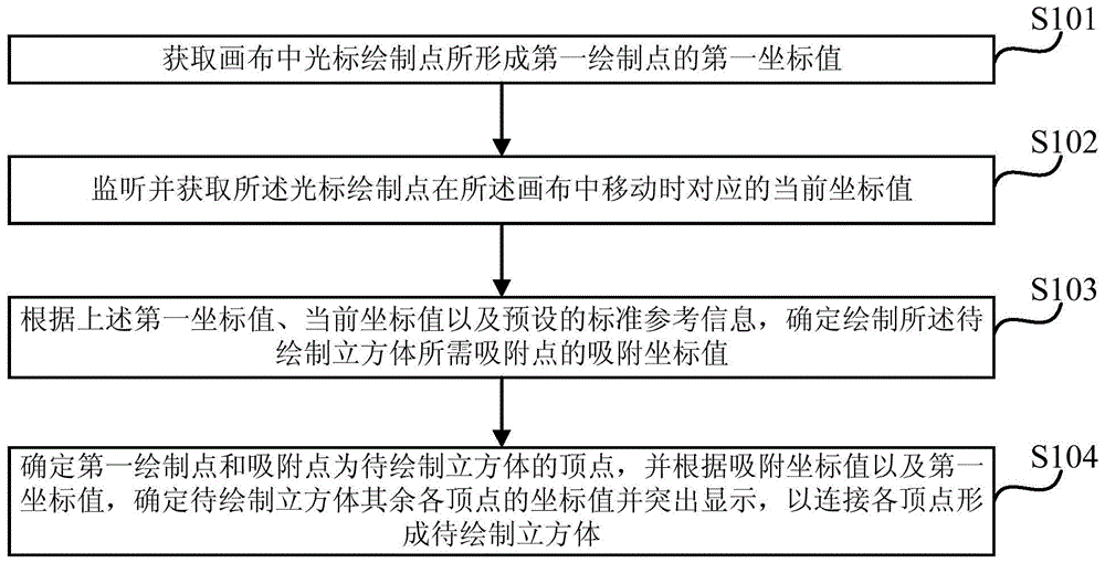
S101、获取画布中光标绘制点所形成第一绘制点的第一坐标值。S101. Acquire a first coordinate value of a first drawing point formed by a cursor drawing point in a canvas.
在本实施例中,所述画布具体可指电子白板中进行绘画操作时显示在设备屏幕上的操作界面。一般地,用户可在画布中通过手指或触屏笔进行触屏绘画,也可在画布中通过对鼠标的操作进行绘画,其中,所述光标绘制点具体可理解为对触屏或鼠标操作进行响应后显示在画布中的绘制标识。In this embodiment, the canvas may specifically refer to an operation interface displayed on the screen of the device when a drawing operation is performed in the electronic whiteboard. Generally, the user can perform touch-screen painting on the canvas with a finger or a touch-screen pen, and can also draw on the canvas by operating a mouse, wherein the cursor drawing point can be specifically understood as performing touch-screen or mouse operations. The draw ID to display in the canvas after the response.
具体地,用户可以在画布的任意区域点击鼠标或单击屏幕,本步骤可在响应上述操作后触发光标绘制点在画布中形成第一绘制点,并可获取第一绘制点在设备的屏幕坐标系上对应的像素坐标值,可以理解的是,本实施例默认所述画布所处的坐标系以第一绘制点为原点,其具有的横纵坐标轴可通过第一绘制点的像素坐标值对上述屏幕坐标系进行平移获得,因此,本实施例中第一绘制点在画布所处坐标系中的第一坐标值可看作(0,0)。Specifically, the user can click the mouse or click the screen in any area of the canvas. In this step, the cursor drawing point can be triggered to form the first drawing point in the canvas after responding to the above operation, and the screen coordinates of the first drawing point on the device can be obtained. It can be understood that in this embodiment, the coordinate system where the canvas is located by default takes the first drawing point as the origin, and its horizontal and vertical axes can pass the pixel coordinate value of the first drawing point. The above screen coordinate system is obtained by translation. Therefore, in this embodiment, the first coordinate value of the first drawing point in the coordinate system where the canvas is located can be regarded as (0,0).
S102、监听并获取所述光标绘制点在所述画布中移动时对应的当前坐标值。S102. Monitor and acquire the current coordinate value corresponding to the cursor drawing point moving in the canvas.
可以理解的是,在绘画过程中,可以通过用户对鼠标的拖拽或在屏幕上的触摸滑动来触发画布中的光标绘制点移动,本步骤可以监听所述画布中光标绘制点的移动操作,并可实时获取光标绘制点在屏幕坐标系中对应的当前像素坐标值,由此,根据上述当前像素坐标值以及第一绘制点的像素坐标值,可以实时确定光标绘制点在画布所处坐标系中对应的当前坐标值。It can be understood that during the drawing process, the movement of the cursor drawing point in the canvas can be triggered by the user dragging the mouse or touching and sliding on the screen, and this step can monitor the movement operation of the cursor drawing point in the canvas, The current pixel coordinate value corresponding to the cursor drawing point in the screen coordinate system can be obtained in real time. Therefore, according to the current pixel coordinate value and the pixel coordinate value of the first drawing point, the coordinate system where the cursor drawing point is located on the canvas can be determined in real time. The corresponding current coordinate value in .
S103、根据上述第一坐标值、当前坐标值以及预设的标准参考信息,确定绘制所述待绘制立方体所需吸附点的吸附坐标值。S103: Determine the adsorption coordinate value of the adsorption point required for drawing the cube to be drawn according to the first coordinate value, the current coordinate value and the preset standard reference information.
在本实施例中,所述第一坐标值具体可指上述第一绘制点在画布所处坐标系中具有的坐标值(一般记为(0,0));所述当前坐标值具体可指光标绘制点移动时当前在画布所处坐标系中具有的坐标值(通常可根据光标绘制点在屏幕坐标系中的当前像素坐标值以及第一绘制点的像素坐标值确定)。In this embodiment, the first coordinate value may specifically refer to the coordinate value (generally denoted as (0,0)) of the first drawing point in the coordinate system where the canvas is located; the current coordinate value may specifically refer to The coordinate value currently in the coordinate system where the canvas is located when the cursor drawing point moves (usually can be determined according to the current pixel coordinate value of the cursor drawing point in the screen coordinate system and the pixel coordinate value of the first drawing point).
此外,所述标准参考信息具体可指预先设定的用于立方体绘制时吸附点确定的参考信息。具体地,所述标准参考信息可以根据标准正方体模型到画布中投影后投影坐标值确定,其中,所述标准参考信息可以包括画布中作为标准正方体模型顶面的一条边与画布所在横坐标轴所形成夹角的夹角值、作为标准正方体顶面的两条邻边所形成夹角的夹角值以及标准正方体模型投影时对应的变化矩阵等,以用于后续绘制立方体所需吸附点的确定。In addition, the standard reference information may specifically refer to preset reference information for determining the adsorption point during cube rendering. Specifically, the standard reference information may be determined according to the projected coordinate values after the standard cube model is projected onto the canvas, wherein the standard reference information may include an edge in the canvas serving as the top surface of the standard cube model and the position of the horizontal axis where the canvas is located. The included angle value of the included angle, the included angle value of the included angle formed by the two adjacent sides as the top surface of the standard cube, and the corresponding change matrix when the standard cube model is projected, etc., are used for the determination of the adsorption points required for subsequent drawing of the cube .
一般地,在进行立方体绘制时,需要保证所绘制立方体的长边、宽边以及高边具有相等的长度值,在现有电子白板中绘画时,用户无法直接确定保证立方体长宽高相等的顶点,由此本实施例提供了立方体的绘制方法,以通过确定吸附点作为待绘制立方体的顶点,来保证待绘制立方体的长边、宽边以及高边具有相同的长度。Generally, when drawing a cube, it is necessary to ensure that the long side, wide side and high side of the drawn cube have equal length values. When drawing on an existing electronic whiteboard, the user cannot directly determine the vertices that ensure equal length, width and height of the cube. Therefore, this embodiment provides a method for drawing a cube, so as to ensure that the long side, the wide side and the high side of the to-be-drawn cube have the same length by determining the adsorption point as the vertex of the to-be-drawn cube.
示例性地,进行吸附点确定的操作可描述为:首先将第一绘制点作为待绘制立方体顶面上的第一顶点,同时将移动的光标绘制点作为待绘制立方体顶面上的第二顶点,且可设定第一顶点与第二顶点为构成顶面的对顶点,此时可确定第一顶点为固定点,第二顶点为移动点,获取到第二顶点移动时对应到当前坐标值后,可以根据第一顶点的第一坐标值、第二顶点的当前坐标值以及标准参考信息,确定构成待绘制立方体顶面的另外两个顶点的当前坐标值;之后可根据第一顶点以及其余三个顶点的当前坐标值获得待绘制立方体的长边和宽边的当前长度值,然后可假设长边和宽边的当前长度值相等,由此可确定长边和宽边相等时第二顶点应该具有的理想坐标值,本步骤将该理想坐标值作为吸附坐标值,将其对应的坐标点作为吸附点,由此可将第二顶点吸附固定到所述吸附点对应的位置上。Exemplarily, the operation of determining the adsorption point can be described as: first, the first drawing point is used as the first vertex on the top surface of the cube to be drawn, and the moving cursor drawing point is used as the second vertex on the top surface of the cube to be drawn. , and the first vertex and the second vertex can be set as the opposite vertices constituting the top surface. At this time, it can be determined that the first vertex is a fixed point, and the second vertex is a moving point, and the current coordinate value corresponding to the movement of the second vertex is obtained. Then, the current coordinate values of the other two vertices that constitute the top surface of the cube to be drawn can be determined according to the first coordinate value of the first vertex, the current coordinate value of the second vertex, and the standard reference information; The current coordinate values of the three vertices obtain the current length values of the long side and the wide side of the cube to be drawn, and then it can be assumed that the current length values of the long side and the wide side are equal, so it can be determined that the second vertex when the long side and the wide side are equal The ideal coordinate value that should be there, this step is taken as the adsorption coordinate value, and the corresponding coordinate point is taken as the adsorption point, so that the second vertex can be adsorbed and fixed to the position corresponding to the adsorption point.
可以理解的是,经过上述操作可以确定一个吸附点,根据所确定的吸附点仅可保证待绘制立方体的长边和宽边相等,无法保证高边等同于长边和宽边,因此需要确定待绘制立方体所需的下一吸附点。It can be understood that an adsorption point can be determined through the above operations. According to the determined adsorption point, only the long side and the wide side of the cube to be drawn can be guaranteed to be equal, and the high side cannot be guaranteed to be equal to the long side and the wide side. Therefore, it is necessary to determine the The next snap point required to draw the cube.
示例性地,确定下一吸附点的操作可表述为:在将第二顶点固定到吸附点对应的位置后,再次监听光标绘制点的移动,并确定移动时在画布中的当前坐标值;然后将第二顶点与光标绘制点的连线看作待绘制立方体的高边,根据第二顶点对应的吸附坐标值以及光标绘制点的当前坐标值,确定高边的当前长度值,之后可假设高边的当前长度值与上述长边或宽边的长度值相等,由此可确定高边与长边或宽边相等时光标绘制点应该具有的理想坐标值,本步骤可将该理想坐标值作为下一吸附点的吸附坐标值,同时可将光标绘制点吸附固定到下一吸附点对应的位置上。Exemplarily, the operation of determining the next adsorption point can be expressed as: after the second vertex is fixed to the position corresponding to the adsorption point, monitor the movement of the cursor drawing point again, and determine the current coordinate value in the canvas when moving; then The line connecting the second vertex and the cursor drawing point is regarded as the high side of the cube to be drawn, and the current length value of the high side is determined according to the adsorption coordinate value corresponding to the second vertex and the current coordinate value of the cursor drawing point, and then the high side can be assumed. The current length value of the side is equal to the length value of the above-mentioned long side or wide side, so the ideal coordinate value that the cursor drawing point should have when the high side is equal to the long side or wide side can be determined. In this step, the ideal coordinate value can be used as The adsorption coordinate value of the next adsorption point, and the cursor drawing point can be fixed to the position corresponding to the next adsorption point.
经过上述操作,最终确定了绘制立方体所需的至少两个吸附点的吸附坐标值。本实施例后续操作将上述确定的吸附点作为待绘制立方体的顶点,由此保证所绘制立方体的长宽高相等。After the above operations, the adsorption coordinate values of at least two adsorption points required to draw the cube are finally determined. Subsequent operations in this embodiment use the above-determined adsorption point as the vertex of the cube to be drawn, thereby ensuring that the drawn cube has the same length, width and height.
S104、确定第一绘制点和吸附点为待绘制立方体的顶点,并根据吸附坐标值以及第一坐标值,确定待绘制立方体其余各顶点的坐标值并突出显示,以连接各顶点形成待绘制立方体。S104. Determine the first drawing point and the adsorption point as the vertices of the cube to be drawn, and determine the coordinate values of the remaining vertices of the cube to be drawn according to the adsorption coordinate value and the first coordinate value and highlight them, so as to connect the vertices to form the cube to be drawn .
在本实施例中,首先可以将所述第一绘制点以及所确定的吸附点作为待绘制立方体的固定顶点,之后,可根据上述已确定第一绘制点以及吸附点的坐标值,结合预设的标准参考信息确定所述待绘制立方体其中各顶点的坐标值,并可突出显示,最终,连接突出显示的各顶点,从而在画布中形成长宽高相等立方体。In this embodiment, firstly, the first drawing point and the determined adsorption point may be used as fixed vertices of the cube to be drawn, and then, according to the coordinate values of the determined first drawing point and the adsorption point, in combination with a preset The standard reference information of the to-be-drawn cube determines the coordinate value of each vertex in the cube to be drawn, and can be highlighted. Finally, each highlighted vertex is connected to form a cube of equal length, width and height in the canvas.
本发明实施例一提供的一种立方体图形的绘制方法,能够根据所获取第一绘制点的第一坐标值、所监听光标绘制点的当前坐标值以及预设的用于立方体绘制的标准参考信息,确定画布中绘制立方体所需的吸附点,最终根据确定的吸附点坐标值以及第一绘制点的第一坐标值确定立方体中各顶点对应的坐标值,在画布中实现立方体的绘制。利用该方法,能够在电子白板的画布中简单方便的实现立方体的绘制,由此更好的增强了电子白板中绘画功能的用户体验。Embodiment 1 of the present invention provides a method for drawing a cube graph, which can be based on the acquired first coordinate value of the first drawing point, the current coordinate value of the monitored cursor drawing point, and the preset standard reference information for cube drawing. , determine the adsorption point required for drawing the cube on the canvas, and finally determine the coordinate value corresponding to each vertex in the cube according to the determined coordinate value of the adsorption point and the first coordinate value of the first drawing point, and realize the drawing of the cube on the canvas. By using the method, the drawing of the cube can be realized simply and conveniently on the canvas of the electronic whiteboard, thereby better enhancing the user experience of the drawing function in the electronic whiteboard.
实施例二Embodiment 2
图2a为本发明实施例二提供的一种立方体图形的绘制方法的流程示意图。本发明实施例以上述实施例为基础进行优化,在本实施例中,优化增加了:将标准正方体模型投影到所述画布中,获取所述标准正方体模型中各顶点在所述画布中的投影坐标值;根据各顶点在所述画布中的投影坐标值,确定所述标准正方体模型在所述画布中的标准参考信息。FIG. 2a is a schematic flowchart of a method for drawing a cube graph according to Embodiment 2 of the present invention. The embodiment of the present invention performs optimization based on the above-mentioned embodiment. In this embodiment, the optimization adds: project the standard cube model into the canvas, and obtain the projection of each vertex in the standard cube model on the canvas Coordinate value; according to the projected coordinate value of each vertex in the canvas, determine the standard reference information of the standard cube model in the canvas.
如图2a所示,本发明实施例二提供的一种立方体图形的绘制方法,具体包括如下操作:As shown in FIG. 2a, a method for drawing a cube graph provided in Embodiment 2 of the present invention specifically includes the following operations:
可以理解的是,本实施例在上述实施例的基础上增加了S201和S202,进而实现了标准参考信息的确定。It can be understood that this embodiment adds S201 and S202 on the basis of the above-mentioned embodiment, thereby realizing the determination of the standard reference information.
S201、将标准正方体模型投影到画布中,获取标准正方体模型中各顶点在画布中的投影坐标值。S201. Project the standard cube model onto the canvas, and obtain the projected coordinate values of each vertex in the standard cube model on the canvas.
本实施例中,可以首先对标准正方体模型进行投影处理,获取标准正方体模型在画布中的投影信息,以用于后续立方体绘制时吸附点的确定。需要说明的是,本实施例所采用的标准正方体模型可通过构建函数构建,且构建出的标准正方体模型具有相应的空间坐标信息。本步骤可以根据标准正方体模型具有的空间坐标信息以及选取的投影变换矩阵实现标准正方体模型到二维画布的投影;还可以直接调用电子设备操作系统函数库中的投影所需的函数集合实现标准正方体模型的投影。In this embodiment, projection processing can be performed on the standard cube model first, and the projection information of the standard cube model on the canvas can be obtained, which is used to determine the adsorption point during subsequent cube drawing. It should be noted that the standard cube model used in this embodiment can be constructed by a construction function, and the constructed standard cube model has corresponding spatial coordinate information. In this step, the projection of the standard cube model to the two-dimensional canvas can be realized according to the spatial coordinate information of the standard cube model and the selected projection transformation matrix; the function set required for the projection in the function library of the operating system of the electronic device can also be directly called to realize the standard cube Projection of the model.
进一步地,本实施例将所述将标准正方体模型投影到所述画布中,获取所述标准正方体模型中各顶点在所述画布中的投影坐标值,具体优化为:在构建的三维场景中调用预设的虚拟透视相机,根据所述虚拟透视相机在所述画布中对设定的标准正方体模型进行投影;调用设定的投影坐标确定函数,根据所述标准正方体模型各顶点的空间坐标值,确定各顶点在所述画布中的投影坐标值。Further, in this embodiment, the standard cube model is projected into the canvas, and the projected coordinate values of each vertex in the standard cube model in the canvas are obtained, and the specific optimization is: calling in the constructed three-dimensional scene. The preset virtual perspective camera projects the set standard cube model in the canvas according to the virtual perspective camera; calls the set projection coordinate determination function, and according to the spatial coordinate value of each vertex of the standard cube model, Determine the projected coordinate value of each vertex in the canvas.
在本实施例中,优选地采用操作系统函数库中的投影函数集合实现标准正方体模型到画布的投影,其将标准立方体模型投影到画布的具体过程可描述为:首先调用三维场景的构建函数构建一个三维场景;然后在该三维场景中添加预设的虚拟照相机,其中,该虚拟照相机优选为虚拟透视相机;之后调用正方体构建函数在三维场景中构建一个棱长为1的标准正方体模型,最终通过添加的虚拟透视相机将构建的标准正方体模型投影到二维平面上,并可调用投影坐标确定函数根据标准正方体模型的空间坐标信息获取标准正方体模型各顶点在二维平面上对应的投影坐标值。In this embodiment, the projection function set in the operating system function library is preferably used to realize the projection of the standard cube model to the canvas. The specific process of projecting the standard cube model to the canvas can be described as follows: first, the construction function of the three-dimensional scene is called to construct A three-dimensional scene; then add a preset virtual camera in the three-dimensional scene, wherein, the virtual camera is preferably a virtual perspective camera; then call the cube construction function to construct a standard cube model with an edge length of 1 in the three-dimensional scene, and finally pass The added virtual perspective camera projects the constructed standard cube model onto the two-dimensional plane, and can call the projection coordinate determination function to obtain the corresponding projected coordinate values of each vertex of the standard cube model on the two-dimensional plane according to the spatial coordinate information of the standard cube model.
S202、根据各顶点在画布中的投影坐标值,确定标准正方体模型在画布中的标准参考信息。S202. Determine the standard reference information of the standard cube model in the canvas according to the projected coordinate values of the vertices in the canvas.
在本实施例中,可以根据各顶点在画布中的投影坐标值,在画布中连接形成一个平面的标准正方体。进一步地,本步骤中所述标准参考信息的确定操作可以通过图2b所示的操作步骤实现,其中,图2b为本发明实施例二中进行标准参考信息确定的具体操作流程图,同时,图2c为进行标准参考信息确定时标准立方体模型在画布中的投影示意图。如图2b所示,进行标准参考信息确定的具体操作步骤包括:In this embodiment, standard cubes that form a plane can be connected in the canvas according to the projected coordinate values of the vertices in the canvas. Further, the determination operation of the standard reference information described in this step can be realized through the operation steps shown in FIG. 2 b , wherein FIG. 2 b is a specific operation flowchart for determining the standard reference information in Embodiment 2 of the present invention, and at the same time, FIG. 2c is a schematic diagram of the projection of the standard cube model on the canvas when the standard reference information is determined. As shown in Figure 2b, the specific operation steps for determining the standard reference information include:
S2021、将画布中表示标准正方体模型顶面的顶点记为第一顶点SP1、第二顶点SP2、第三顶点SP3以及第四顶点SP4,并将与所述SP2相对的底面顶点记为第六顶点SP6。S2021: Denote the vertices representing the top surface of the standard cube model in the canvas as the first vertex SP1, the second vertex SP2, the third vertex SP3 and the fourth vertex SP4, and denote the bottom vertex opposite to the SP2 as the sixth vertex SP6.
示例性地,如图2c所示,画布20处于屏幕坐标系XOY中,在画布20中点SP1、点SP2、点SP3以及点SP4构成了标准正方体模型的顶面,同时可以确定点SP1和点SP2为顶面中的对顶点;此外,根据图2c所示,在画布20中点SP5、点SP6、点SP7以及点SP8分别与点SP1、点SP2、点SP3以及点SP4相对,并构成了标准正方体模型的底面。Exemplarily, as shown in FIG. 2c, the
S2022、将SP1与SP3形成的边记为宽边SH1,将SP3与SP2形成的边为长边SH2,以及将SP2与SP6形成的边记为高边SH3。S2022: Denote the side formed by SP1 and SP3 as the broad side SH1, the side formed by SP3 and SP2 as the long side SH2, and the side formed by SP2 and SP6 as the high side SH3.
示例性地,如图2c所示,点SP1和点SP3的连接形成了标准正方体模型的宽边SH1,点SP2和点SP3的连接形成了标准正方体模型的长边SH2,同时,点SP2和点SP6的连接形成了标准正方体模型的宽边SH3。Exemplarily, as shown in Figure 2c, the connection of points SP1 and SP3 forms the broad side SH1 of the standard cube model, the connection of points SP2 and SP3 forms the long side SH2 of the standard cube model, and at the same time, the point SP2 and the point The connection of SP6 forms the broad side SH3 of the standard cube model.
S2023、根据SP1、SP2、SP3、SP4以及SP6的投影坐标值,确定所述SH1、SH2以及SH3的长度值,并确定SH1与SH2所形成夹角的第一夹角值以及所述SH2与画布所在横坐标轴所形成夹角的第二夹角值。S2023, according to the projected coordinate values of SP1, SP2, SP3, SP4 and SP6, determine the length values of the SH1, SH2 and SH3, and determine the first angle value of the included angle formed by SH1 and SH2, and the SH2 and the canvas The second included angle value of the included angle formed by the abscissa axis.
示例性地,为便于标准参考信息的表示,如图2c所示,本实施例以点SP1为原点构建了平行于屏幕坐标系XOY的xoy坐标系,需要说明的是,本实施例中各点的投影坐标值为xoy坐标系,由此本实施例可以根据各点的投影坐标值确定SH1、SH2以及SH3的长度值,同时可以确定上述各边在xoy坐标系中向量,如,可确定点SP1与点SP3的向量V1,点SP3与点SP2的向量V2,以及点SP1与点SP4的向量V3,点SP1与xoy坐标系中点(1,0)的向量为V4。Exemplarily, in order to facilitate the representation of standard reference information, as shown in FIG. 2c, this embodiment uses point SP1 as the origin to construct an xoy coordinate system parallel to the screen coordinate system XOY. It should be noted that each point in this embodiment The projected coordinate value of the xoy coordinate system, so this embodiment can determine the length values of SH1, SH2 and SH3 according to the projected coordinate value of each point, and can determine the vectors of the above sides in the xoy coordinate system. For example, the point can be determined The vector V1 of SP1 and point SP3, the vector V2 of point SP3 and point SP2, and the vector V3 of point SP1 and point SP4, the vector of point SP1 and point (1,0) in the xoy coordinate system is V4.
此外,如图2c所示,可确定SH1与SH2所形成夹角为β,SH2与画布20所在横坐标轴所形成的夹角相当于SH2与xoy坐标系中x轴所形成的夹角,记为ɑ。具体地,本实施例可以根据向量积公式确定夹角β的第一夹角值以及夹角ɑ的第二夹角值,接上述示例,可确定β的第一夹角值为β=arccos(V1·V2/|V1||V2|);以及可确定ɑ的第二夹角值为ɑ=arccos(V4·V3/|V4||V3|)。In addition, as shown in Figure 2c, it can be determined that the angle formed by SH1 and SH2 is β, and the angle formed by SH2 and the abscissa axis where the
S2024、将画布当前所处的坐标系作为第一坐标系,并将以SH2作为横坐标轴的坐标系看作第二坐标系。S2024, taking the coordinate system where the canvas is currently located as the first coordinate system, and taking the coordinate system with SH2 as the abscissa axis as the second coordinate system.
示例性地,如图2c所示,由于画布20当前所处的坐标系为xoy坐标系,因此xoy坐标系可记为第一坐标系,同时可以看出,x`oy`坐标系中的横坐标轴为SH2,由此x`oy`坐标系可记为第二坐标系。Exemplarily, as shown in FIG. 2c, since the coordinate system where the
S2025、根据第一夹角值和第二夹角值,确定第一坐标系变换为第二坐标系时对应的第一变换矩阵Mo,以及第二坐标系变换为第一坐标系时对应的第二变换矩阵Mo`。S2025, according to the first included angle value and the second included angle value, determine the first transformation matrix Mo corresponding when the first coordinate system is transformed into the second coordinate system, and the first transformation matrix Mo corresponding when the second coordinate system is transformed into the first coordinate system Two transformation matrix Mo`.
示例性地,如图2c所示,xoy坐标系到x`oy`坐标系的变换,相当于xoy坐标系顺时针旋转了夹角ɑ变换为x`oy`坐标系,在本实施例中,根据坐标变换规则以及变换夹角ɑ对应的第二夹角值,可确定其对应的变换矩阵Mo可表示为:

S2026、将第一夹角值、Mo和Mo`以及所述SH1、SH2以及SH3的长度值作为预设的标准参考信息。S2026. Use the first included angle value, Mo and Mo', and the length values of SH1, SH2, and SH3 as preset standard reference information.
本实施例中,可以将SH1与SH2所形成夹角β的第一夹角值、第一变换矩阵Mo、第二变换矩阵Mo`看作标准参考信息,同时还将宽边SH1、长边SH2以及高边SH3看作标准参考信息,以供后续操作使用。In this embodiment, the first angle value of the angle β formed by SH1 and SH2, the first transformation matrix Mo, and the second transformation matrix Mo' can be regarded as standard reference information, and the broad side SH1 and the long side SH2 And high-side SH3 as standard reference information for subsequent operations.
S203、获取画布中光标绘制点所形成第一绘制点的第一坐标值。S203: Acquire the first coordinate value of the first drawing point formed by the cursor drawing point in the canvas.
示例性地,可以响应用户点击鼠标触发光标绘制点在所述画布中形成第一绘制点,且可以以所述第一绘制点为原点构建所述画布所处的第一坐标系,由此,所述第一绘制点的第一坐标值可看作(0,0),可以理解的是,所述第一坐标系可以由屏幕坐标系根据所述第一绘制点在屏幕坐标系中的像素坐标值平移获得。Exemplarily, a first drawing point can be formed in the canvas by triggering a cursor drawing point in response to a user clicking a mouse, and a first coordinate system in which the canvas is located can be constructed with the first drawing point as an origin, thus, The first coordinate value of the first drawing point can be regarded as (0,0). It can be understood that the first coordinate system can be determined by the screen coordinate system according to the pixels of the first drawing point in the screen coordinate system. The coordinate value is obtained by translation.
S204、监听并获取所述光标绘制点在所述画布中移动时对应的当前坐标值。S204. Monitor and acquire the current coordinate value corresponding to the cursor drawing point when it moves in the canvas.
示例性地,可以监听光标绘制点在画布中的移动,并可获取光标绘制点在屏幕坐标系中对应当前像素坐标值,由此可以根据所述当前像素坐标值,确定光标绘制点在画布所处第一坐标系中的当前坐标值。Exemplarily, the movement of the cursor drawing point in the canvas can be monitored, and the current pixel coordinate value corresponding to the cursor drawing point in the screen coordinate system can be obtained, so that it can be determined according to the current pixel coordinate value that the cursor drawing point is on the canvas. the current coordinate value in the first coordinate system.
S205、根据第一坐标值、当前坐标值以及预设的标准参考信息,确定绘制所述待绘制立方体所需吸附点的吸附坐标值。S205 , according to the first coordinate value, the current coordinate value and the preset standard reference information, determine the adsorption coordinate value of the adsorption point required to draw the cube to be drawn.
在本实施例中,可以根据第一绘制点在第一坐标系中的第一坐标值,光标绘制点的当前坐标值以及预先确定的标准正方体模型投影后所获得的第一夹角值、第一变换矩阵以及第二变换矩阵等标准参考信息,确定待绘制立方体所需吸附点的吸附坐标值。In this embodiment, according to the first coordinate value of the first drawing point in the first coordinate system, the current coordinate value of the cursor drawing point, and the first included angle value, the third Standard reference information such as a transformation matrix and a second transformation matrix to determine the adsorption coordinate value of the adsorption point required for the cube to be drawn.
进一步地,本步骤中吸附坐标值的确定操作可以通过图2d所示的操作流程实现,其中,图2d为本发明实施例二中进行吸附坐标值确定的具体操作流程图,同时,图2e为进行第一吸附坐标值确定时的效果展示图;图2f为进行第二吸附坐标值确定时的效果展示图。如图2d所示,进行吸附坐标值确定的具体操作步骤包括:Further, the determination operation of the adsorption coordinate value in this step can be realized through the operation flow shown in FIG. 2d, wherein, FIG. 2d is the specific operation flow chart of determining the adsorption coordinate value in Embodiment 2 of the present invention, and at the same time, FIG. An effect display diagram when the first adsorption coordinate value is determined; FIG. 2f is an effect display diagram when the second adsorption coordinate value is determined. As shown in Figure 2d, the specific operation steps for determining the adsorption coordinate value include:
S2051、将第一绘制点和光标绘制点作为待绘制立方体中顶面的两个顶点,分别记为P1和P2,其中,所述P1和P2在所述顶面中互为对顶点。S2051 , taking the first drawing point and the cursor drawing point as two vertices of the top surface of the cube to be drawn, and denoted as P1 and P2 respectively, wherein the P1 and P2 are opposite vertices on the top surface.
示例性地,如图2e所示,XOY为电子设备的屏幕坐标系,画布20处于该屏幕坐标系中,其中,光标绘制点触发所形成的第一绘制点P1可以看作画布20所处坐标系xoy的原点,且P1可看作待绘制立方体顶面中的一个顶点,其对应的第一坐标值可记为(0,0),在画布20中移动的光标绘制点可作为待绘制立方体顶面的另一个顶点P2,其在xoy坐标系中具有的当前坐标值可通过S204确定。需要知道的是,本实施例将点P1和点P2设置为顶面上的对顶点。Exemplarily, as shown in FIG. 2e, XOY is the screen coordinate system of the electronic device, and the
S2052、根据第一夹角值、Mo和Mo`以及P1的第一坐标值和P2的当前坐标值,确定待绘制立方体中顶面的第三顶点P3和第四顶点P4在第一坐标系中的当前坐标值。S2052, according to the first included angle value, Mo and Mo', the first coordinate value of P1 and the current coordinate value of P2, determine that the third vertex P3 and the fourth vertex P4 of the top surface in the cube to be drawn are in the first coordinate system the current coordinate value of .
本步骤可将待绘制立方体顶面中的其余顶点分别记为第三顶点P3和第四顶点P4,在本实施例中,进行待绘制立方体绘制时,为保证所绘制图形为立方体,首先需要将点P1和点P4所形成棱长HP1P4与x轴之间的夹角默认为ɑ,即,保证HP1P4与x轴所形成夹角的角度值为第二夹角值;同时,还需将点P1和点P3所形成第一棱长HP1P3与点P3和点P2所形成第二棱长HP2P3之间的夹角默认为β,即,保证HP1P3与HP2P3所形成夹角的角度值为第一夹角值。In this step, the remaining vertices on the top surface of the cube to be drawn can be recorded as the third vertex P3 and the fourth vertex P4 respectively. In this embodiment, when drawing the cube to be drawn, in order to ensure that the drawn figure is a cube, it is first necessary to set the The angle between the edge length H P1P4 formed by the point P1 and the point P4 and the x-axis is ɑ by default, that is, to ensure that the angle formed by the H P1P4 and the x-axis is the second angle value; The angle between the first edge length H P1P3 formed by point P1 and point P3 and the second edge length H P2P3 formed by point P3 and point P2 is β by default, that is, the angle that ensures the angle formed by H P1P3 and H P2P3 The value is the value of the first included angle.
本步骤根据P1和P2在xoy坐标系中的坐标值以及标准参考信息中记录的第一夹角值、Mo和Mo`,可以确定点P3和点P4在xoy坐标系中对应的当前坐标值(点P3和点P4仅是计算出的当前坐标值,因此图2e中各点之间的连接用虚线表示)。具体地,根据第一变换矩阵Mo,可以确定点P1和点P2在第二坐标系x`oy`上的坐标值,其中,P1`=P1*Mo;P2`=P2*Mo;将点P3`和点P4`分别记为点P3和点P4在第二坐标系中的对应点,则点P3`和点P4`在x`oy`中的坐标值可通过下述公式计算:In this step, according to the coordinate values of P1 and P2 in the xoy coordinate system and the first included angle value, Mo and Mo' recorded in the standard reference information, the current coordinate values ( Points P3 and P4 are only the calculated current coordinate values, so the connections between the points in Figure 2e are indicated by dotted lines). Specifically, according to the first transformation matrix Mo, the coordinate values of the point P1 and the point P2 on the second coordinate system x`oy` can be determined, wherein, P1`=P1*Mo; P2`=P2*Mo; ` and point P4` are respectively recorded as the corresponding points of point P3 and point P4 in the second coordinate system, then the coordinate values of point P3` and point P4` in x`oy` can be calculated by the following formula:
P3`=[P1`.x–(P2`.y–P1`.y)*cotβ,P2`.y] (1)P3` = [P1`.x – (P2`.y – P1`.y)*cotβ, P2`.y] (1)
P4`=[P1`.x+(P2`.x–P3`.x),P1`.y] (2)P4`=[P1`.x+(P2`.x–P3`.x), P1`.y] (2)
之后,根据第二变换矩阵Mo`,可确定P3=P3`*Mo`以及P4=P4`*Mo`,进而可确定点P3`和点P4`转换到xoy坐标系中后所对应点P3和点P4的当前坐标值(图2e中示出了点P3和点P4的当前所在位置)。Afterwards, according to the second transformation matrix Mo`, P3=P3`*Mo` and P4=P4`*Mo` can be determined, and then the corresponding points P3 and P4` after the point P3` and point P4` are converted into the xoy coordinate system can be determined. The current coordinate value of point P4 (the current positions of points P3 and P4 are shown in FIG. 2e).
S2053、根据P1的第一坐标值以及P2、P3以及P4的当前坐标值,确定第一棱长HP1P3以及第二棱长HP2P3的当前棱长值,并根据HP1P3和HP2P3的当前棱长值以及SH1和SH2的长度值,确定HP1P3对应的第一比率值R1和HP2P3对应的第二比率值R2。S2053: Determine the current edge length values of the first edge length H P1P3 and the second edge length H P2P3 according to the first coordinate value of P1 and the current coordinate values of P2, P3 and P4, and according to the current edge lengths of H P1P3 and H P2P3 The length value and the length values of SH1 and SH2 determine the first ratio value R1 corresponding to HP1P3 and the second ratio value R2 corresponding to HP2P3 .
在本实施例中,所述第一棱长HP1P3相当于待绘制立方体的宽边,所述第二棱长HP2P3相当于待绘制立方体的长边,为保证待绘制立方体的长宽高相等,首先需要保证HP1P3(宽边)与HP2P3(长边)相等。In this embodiment, the length of the first edge H P1P3 is equivalent to the wide side of the cube to be drawn, and the length of the second edge H P2P3 is equivalent to the long side of the cube to be drawn. In order to ensure that the length, width and height of the cube to be drawn are equal , first of all, it is necessary to ensure that HP1P3 (wide side) and HP2P3 (long side) are equal.
由此本实施例可以根据点P1的第一坐标值以及点P2、点P3和点P4的当前坐标值,确定第一棱长HP1P3以及第二棱长HP2P3的当前棱长值;之后可以根据HP1P3和HP2P3的当前棱长值以及标准参考信息中SH1和SH2的长度值,通过公式R1=HP1P3/SH1;R2=HP2P3/SH2确定HP1P3对应的第一比率值R1和所述HP2P3对应的第二比率值R2,以通过各边对应的比率值根据后续吸附坐标值的确定操作保证HP1P3(宽边)与HP2P3(长边)相等。Therefore, the present embodiment can determine the current edge length values of the first edge length H P1P3 and the second edge length H P2P3 according to the first coordinate value of the point P1 and the current coordinate values of the point P2, the point P3 and the point P4; According to the current edge length values of HP1P3 and HP2P3 and the length values of SH1 and SH2 in the standard reference information, the first ratio value R1 and the corresponding first ratio value R1 corresponding to HP1P3 are determined by formula R1= HP1P3 /SH1; R2= HP2P3 /SH2 The second ratio value R2 corresponding to HP2P3 is described, so as to ensure that HP1P3 (broad side) and HP2P3 (long side) are equal according to the subsequent determination of adsorption coordinate values through the ratio values corresponding to each side.
S2054、当R1与R2的差值不大于设定阈值时,根据R1和R2以及第一夹角值、Mo和Mo`,确定绘制所述待绘制立方体所需的第一吸附点在第一坐标系中的第一吸附坐标值。S2054, when the difference between R1 and R2 is not greater than the set threshold, according to R1 and R2 and the first included angle value, Mo and Mo', determine that the first adsorption point required to draw the cube to be drawn is at the first coordinate The first adsorption coordinate value in the system.
本实施例中,为保证待绘制立方体中保证HP1P3(宽边)与HP2P3(长边)相等,可以将R1和R2的值进行比对,并确定其差值是否不大于设定阈值,其中,所述设定阈值可以由系统默认设定,也可以根据历史经验人为设定,本实施例优选设定所述设定阈值为0.05。In this embodiment, in order to ensure that H P1P3 (wide side) and H P2P3 (long side) are equal in the cube to be drawn, the values of R1 and R2 can be compared, and it is determined whether the difference is not greater than the set threshold, The set threshold may be set by default by the system, or may be set manually according to historical experience. In this embodiment, the set threshold is preferably set to 0.05.
需要说明的是,当R1和R2的差值大于设定阈值时,本实施例不再进行下述吸附坐标值的确定操作,而是返回S204继续获取光标绘制点移动后重新对应的当前坐标值(本实施例图2a未示出),以及根据光标绘制点的新的当前坐标值重新执行S205(图2a中未示出),且可重复上述操作直至本步骤确定了R1和R2的差值小于或等于设定阈值。It should be noted that when the difference between R1 and R2 is greater than the set threshold, this embodiment does not perform the following determination of the adsorption coordinate value, but returns to S204 to continue to obtain the current coordinate value corresponding to the cursor drawing point after moving. (This embodiment is not shown in Fig. 2a), and re-executes S205 according to the new current coordinate value of the cursor drawing point (not shown in Fig. 2a), and the above operations can be repeated until the difference between R1 and R2 is determined in this step Less than or equal to the set threshold.
具体地,当R1和R2的差值不大于设定阈值时,确定第一吸附点在第一坐标系中的第一吸附坐标值的过程可描述为:步骤(1),选取R1或R2作为标准比率值R,本步骤以R1作为标准比率值R为例,因此可确定R=R1=HP1P3/SH1,由于R为标准比率值,所以可认为当前HP1P3为标准值,之后需要保证R2等于R,以保证待绘制立方体的宽边(HP1P3)与长边(HP2P3)相等,此时,可通过反推公式HP2P3=(HP1P3/SH1)*SH2来确定HP2P3的标准值;步骤(2),在确定HP2P3的标准值后,可以根据HP2P3的标准值、点P1的第一坐标值以及所述第一夹角值、Mo和Mo`,确定点P2待吸附的第一吸附点对应的第一吸附坐标值(为便于表示,直接将待确定的第一吸附点记为P21)。Specifically, when the difference between R1 and R2 is not greater than the set threshold, the process of determining the first adsorption coordinate value of the first adsorption point in the first coordinate system can be described as: Step (1), select R1 or R2 as the The standard ratio value R, this step takes R1 as the standard ratio value R as an example, so it can be determined that R=R1=H P1P3 /SH1, since R is the standard ratio value, it can be considered that the current H P1P3 is the standard value, and then it is necessary to ensure that R2 equal to R, to ensure that the wide side (H P1P3 ) of the cube to be drawn is equal to the long side (H P2P3 ), at this time, the standard value of H P2P3 can be determined by the reverse formula H P2P3 = (H P1P3 /SH1)*SH2 Step (2), after determining the standard value of HP2P3 , can according to the standard value of HP2P3 , the first coordinate value of point P1 and the first included angle value, Mo and Mo', determine the point P2 to be adsorbed The first adsorption coordinate value corresponding to the first adsorption point (for convenience of representation, the to-be-determined first adsorption point is directly recorded as P21).
具体地,上述步骤(2)的过程可描述为:确定光标移动点P2在画布20所处第一坐标系xoy中移动时对应的象限区域,需要说明的是,本实施例将第一吸附点P21看作光标绘制点P2待吸附的点,且点P2处于不同象限时,可以根据不同的坐标计算公式确定点P2待吸附的第一吸附点P21对应的第一吸附坐标值,其中,坐标计算公式包括:Specifically, the process of the above step (2) can be described as: determining the quadrant area corresponding to when the cursor moving point P2 moves in the first coordinate system xoy where the
在第一象限中:In the first quadrant:
P21`=[P1`.x+HP2P3*cotβ+H1,P1`.y–HP2P3*sinβ]P21`=[P1`.x+H P2P3 *cotβ+H1,P1`.y–H P2P3 *sinβ]
在第二象限中:In the second quadrant:
P21`=[P1`.x+HP2P3*cotβ–H1,P1`.y–HP2P3*sinβ]P21`=[P1`.x+H P2P3 *cotβ–H1,P1`.y–H P2P3 *sinβ]
在第三象限中:In the third quadrant:
P21`=[P1`.x–HP2P3*cotβ–H1,P1`.y+HP2P3*sinβ]P21`=[P1`.x–H P2P3 *cotβ–H1,P1`.y+H P2P3 *sinβ]
在第四象限中:In the fourth quadrant:
P21`=[P1`.x–HP2P3*cotβ+H1,P1`.y+HP2P3*sinβ]P21`=[P1`.x–H P2P3 *cotβ+H1,P1`.y+H P2P3 *sinβ]
需要说明的是,上述公式中P1`=P1*Mo,所述HP2P3为根据标准比率值计算所得的标准值,点P21`相当于第一吸附点P21在第二坐标系中x`oy`的对应点,其中,根据P21=P21`*Mo`可以确定第一吸附点P21在第一坐标系xoy中的第一吸附坐标值。It should be noted that, in the above formula, P1`=P1*Mo, the HP2P3 is the standard value calculated according to the standard ratio value, the point P21` is equivalent to the first adsorption point P21 in the second coordinate system x`oy` , wherein the first adsorption coordinate value of the first adsorption point P21 in the first coordinate system xoy can be determined according to P21=P21`*Mo`.
同时,可以看出,图2e中示出的点P2在画布20所处第一坐标系xoy中移动时的象限区域为第四象限,由此可根据第四象限对应的计算公式确定P21的第一吸附坐标值(图2e示出了点P21的所在位置)。At the same time, it can be seen that the quadrant area when the point P2 shown in FIG. 2e moves in the first coordinate system xoy where the
S2055、将P2吸附到第一吸附点的位置上,确定P2的当前坐标值为第一吸附坐标值,并在P2吸附到所述第一吸附点后,记光标绘制点为P6,监听并获取P6在画布中移动时的当前坐标值。S2055. Adsorb P2 to the position of the first adsorption point, determine that the current coordinate value of P2 is the first adsorption coordinate value, and after P2 is adsorbed to the first adsorption point, mark the cursor drawing point as P6, monitor and acquire The current coordinate value of P6 when moving in the canvas.
示例性地,根据S2054确定第一吸附点的第一吸附坐标后,本步骤可以将点P2吸附到第一吸附点P21的位置上,并可将点P2的当前坐标值确定为第一吸附坐标值。如图2f所示,点P2吸附到第一吸附点P21的位置上,点P2与点P21为同一点,图2f中同时示出了点P2吸附到点P21后,待绘制立方体顶面中四个顶点的连接关系(具体以粗虚线示出)。Exemplarily, after the first adsorption coordinate of the first adsorption point is determined according to S2054, in this step, the point P2 can be adsorbed to the position of the first adsorption point P21, and the current coordinate value of the point P2 can be determined as the first adsorption coordinate. value. As shown in Figure 2f, the point P2 is adsorbed to the position of the first adsorption point P21, and the point P2 and the point P21 are the same point. Figure 2f also shows that after the point P2 is adsorbed to the point P21, the four points in the top surface of the cube to be drawn The connection relationship between the vertices (specifically shown with thick dashed lines).
之后,本步骤还将光标绘制点记为P6,光标绘制点P6响应用户的操作,以垂直于画布20纵坐标轴y的轨迹移动,本步骤可以监听光标绘制点的移动,并获取光标绘制点P6的当前像素坐标值,最终根据该当前像素坐标值获得其在第一坐标系xoy中的当前坐标值,图2f示出了点P6在xoy坐标系中的当前位置。After that, this step also marks the cursor drawing point as P6, and the cursor drawing point P6 responds to the user's operation and moves with a trajectory perpendicular to the vertical axis y of the
S2056、根据所述P2的第一吸附坐标值以及所述P6的当前坐标值,确定第三棱长HP2P6的当前棱长值,并根据所述HP2P6的当前棱长值以及所述SH3的长度值,确定所述HP2P6的第三比率值R3。S2056: Determine the current edge length value of the third edge length H P2P6 according to the first adsorption coordinate value of the P2 and the current coordinate value of the P6, and according to the current edge length value of the H P2P6 and the SH3 The length value determines the third ratio value R3 of the HP2P6 .
示例性地,如图2f所示,点P2(P21)与点P6连接形成第三棱长HP2P6,其中,所述第三棱长HP2P6相当于待绘制立方体的高边,本步骤可以根据点P2(P21)的第一吸附坐标值以及点P6的当前坐标值,确定HP2P6的当前棱长值。Exemplarily, as shown in Figure 2f, the point P2 (P21) is connected with the point P6 to form a third edge length H P2P6 , wherein the third edge length H P2P6 is equivalent to the high side of the cube to be drawn, and this step can be based on The first adsorption coordinate value of point P2 (P21) and the current coordinate value of point P6 determine the current edge length value of H P2P6 .
在本实施例中,根据HP2P6的当前棱长值以及标准参考信息中SH3的长度值,通过下述公式可以确定HP2P6对应的第一比率值R3:其中,R3=HP2P6/SH3。In this embodiment, according to the current edge length value of HP2P6 and the length value of SH3 in the standard reference information, the first ratio value R3 corresponding to HP2P6 can be determined by the following formula: R3= HP2P6 /SH3.
S2057、当R3与R1和/或R2的差值不大于设定阈值时,根据R1和/或R2、第一吸附坐标值以及R3,确定绘制所述待绘制立方体所需的第二吸附点在第一坐标系中的第二吸附坐标值。S2057. When the difference between R3 and R1 and/or R2 is not greater than the set threshold, according to R1 and/or R2, the first adsorption coordinate value and R3, determine that the second adsorption point required to draw the cube to be drawn is at The second snap coordinate value in the first coordinate system.
在本实施例中,所述设定阈值同样优选为0.05;根据上述S2054可以通过保证R1和R2相等来保证待绘制立方体的宽边(HP1P3)与长边(HP2P3)相等,本步骤需进一步确定待绘制立方体的高边(HP2P6)同时与宽边(HP1P3)与长边(HP2P3)相等,由此需要确定待绘制立方体中的第二吸附点。In this embodiment, the set threshold is also preferably 0.05; according to the above S2054, it can be ensured that the wide side (H P1P3 ) and the long side (H P2P3 ) of the cube to be drawn are equal by ensuring that R1 and R2 are equal. This step requires It is further determined that the high side (H P2P6 ) of the cube to be drawn is equal to the wide side (H P1P3 ) and the long side (H P2P3 ) at the same time, so the second adsorption point in the to-be-drawn cube needs to be determined.
具体地,确定第二吸附点在第一坐标系中的第二吸附坐标值的过程可描述为:步骤(1),选取R1和/或R2作为标准比率值R,本实施例本以R1作为标准比率值R为例,因此可确定R=R1=HP1P3/SH1,由于R为标准比率值,所以同样可认为当前HP1P3为标准值,为保证待绘制立方体的宽边(HP1P3)与高边(HP2P6)相等,需要保证R3等于R,此时,可通过反推公式HP2P6=(HP1P3/SH1)*SH3获取HP2P6的标准值;步骤(2),在确定HP2P6的标准值后,可以根据HP2P6的标准值、点P2的第一吸附坐标值以及公式P61=[P2.x,P2.y+HP2P6],确定点P6待吸附的第二吸附点对应的第二吸附坐标值(为便于表示,直接将待确定的第一吸附点记为P61,图2f示出了点P61的所在位置),其中,所述HP2P6为根据标准比率值计算所得的标准值。Specifically, the process of determining the second adsorption coordinate value of the second adsorption point in the first coordinate system can be described as: step (1), selecting R1 and/or R2 as the standard ratio value R, in this embodiment, R1 is used as the The standard ratio value R is taken as an example, so it can be determined that R=R1=H P1P3 /SH1. Since R is the standard ratio value, the current H P1P3 can also be considered as the standard value . The high sides (H P2P6 ) are equal, and it is necessary to ensure that R3 is equal to R. At this time, the standard value of H P2P6 can be obtained through the inverse formula H P2P6 = (H P1P3 /SH1)*SH3; step (2), after determining the H P2P6 After the standard value, according to the standard value of HP2P6 , the first adsorption coordinate value of point P2 and the formula P61=[ P2 . Two adsorption coordinate values (for convenience of representation, the first adsorption point to be determined is directly denoted as P61, and FIG. 2f shows the location of point P61), wherein the HP2P6 is the standard value calculated according to the standard ratio value .
S206、确定第一绘制点和吸附点为待绘制立方体的顶点,并根据吸附坐标值以及第一坐标值,确定待绘制立方体其余各顶点的坐标值并突出显示,以连接各顶点形成所述待绘制立方体。S206. Determine the first drawing point and the adsorption point as the vertices of the cube to be drawn, and determine the coordinate values of the remaining vertices of the cube to be drawn according to the adsorption coordinate value and the first coordinate value and highlight them, so as to connect the vertices to form the to-be-drawn cube. Draw the cube.
在本实施例中,可以将确定的第一绘制点、第一吸附点以及第二吸附点确定为待绘制立方体的固定顶点,之后可以根据上述各固定顶点的坐标值以及预设的标准参考信息,确定待绘制立方体中其余各顶点在画布所在坐标系xoy中的坐标值。In this embodiment, the determined first drawing point, the first adsorption point, and the second adsorption point may be determined as the fixed vertices of the cube to be drawn, and then the coordinate values of the fixed vertices and the preset standard reference information may be determined. , determine the coordinate values of the remaining vertices in the cube to be drawn in the coordinate system xoy where the canvas is located.
具体地,本步骤通过下述操作确定待绘制立方体其余各顶点的坐标值:将所述P6吸附到所述第二吸附点的位置上,确定所述P6的当前坐标值为所述第二吸附坐标值;根据所述P1的第一坐标值、P2的第一吸附坐标值和P6的第二吸附坐标值以及所述第一夹角值、Mo和Mo`,确定所述待绘制立方体其余各顶点的坐标值并突出显示,以在画布上连接各顶点形成所述待绘制立方体。Specifically, in this step, the coordinate values of the remaining vertices of the cube to be drawn are determined by the following operations: the P6 is adsorbed to the position of the second adsorption point, and the current coordinate value of the P6 is determined to be the second adsorption point. Coordinate value; according to the first coordinate value of P1, the first adsorption coordinate value of P2, the second adsorption coordinate value of P6, and the first included angle value, Mo and Mo', determine the rest of the cube to be drawn. The coordinate values of the vertices are highlighted, so as to connect the vertices on the canvas to form the to-be-drawn cube.
可以理解的是,在确定第二吸附点P61的第二吸附坐标值后,本步骤同样可以将点P6吸附到第二吸附点P61的位置上,并可将点P6的当前坐标值确定为第二吸附坐标值。图2g为根据吸附点的吸附坐标值确定的待绘制立方体的示例图,如图2g所示,点P6吸附到第二吸附点P61的位置上,标记为P6(P61)。It can be understood that, after the second adsorption coordinate value of the second adsorption point P61 is determined, the point P6 can also be adsorbed to the position of the second adsorption point P61 in this step, and the current coordinate value of the point P6 can be determined as the first adsorption point. Two adsorption coordinate values. FIG. 2g is an example diagram of a cube to be drawn determined according to the adsorption coordinate values of the adsorption points. As shown in FIG. 2g, the point P6 is adsorbed to the position of the second adsorption point P61, which is marked as P6 (P61).
在本实施例中,可以根据第一绘制点P1的第一坐标值以及第一吸附点P2(P21)的第一吸附坐标值,再次通过本实施例中的公式(1)和公式(2)确定第二坐标系x`oy`下点P3`和点P4`的坐标值,由此再根据第二变换矩阵Mo`以及点P3`和点P4`的坐标值,确定第一坐标系xoy下点P3和点P4的坐标值,并可突出显示。In this embodiment, according to the first coordinate value of the first drawing point P1 and the first adsorption coordinate value of the first adsorption point P2 (P21), formula (1) and formula (2) in this embodiment can be used again. Determine the coordinate values of point P3` and point P4` under the second coordinate system x`oy`, and then determine the first coordinate system xoy according to the second transformation matrix Mo` and the coordinate values of point P3` and point P4` Coordinate values of point P3 and point P4 and can be highlighted.
进一步地,本实施中待绘制立方体顶面上的顶点为P1、P2、P3以及P4,而点P5、P6、P7以及P8为待绘制立方体底面上的分别与上述各点对应的顶点,因此,本实施例可以根据所确定出的点P3和点P4的坐标值,以及HP2P6的标准值,根据下述公式分别确定点P5、点P7以及点P8的坐标值并突出显示:Further, in this implementation, the vertices on the top surface of the cube to be drawn are P1, P2, P3 and P4, and the points P5, P6, P7 and P8 are respectively the vertices corresponding to the above-mentioned points on the bottom surface of the cube to be drawn. Therefore, In this embodiment, according to the determined coordinate values of point P3 and point P4, and the standard value of H P2P6 , the coordinate values of point P5, point P7 and point P8 can be respectively determined and highlighted according to the following formula:
P5=[P1.X,P2.Y+H3]P5=[P1.X,P2.Y+H3]
P7=[P3.X,P3.Y+H3]P7=[P3.X, P3.Y+H3]
P8=[P4.X,P4.Y+H3]P8=[P4.X, P4.Y+H3]
在本实施例中,可以对上述确定出的并突出显示的各顶点进行连接,由此形成所需的待绘制立方体(如图2g所示),可以确定的是,所绘制出的待绘制立方体中的长边、宽边以及高边相等。In this embodiment, the above determined and highlighted vertices can be connected to form the required cube to be drawn (as shown in FIG. 2g ). It can be determined that the drawn cube to be drawn The long side, wide side, and high side are equal.
本发明实施例二提供的一种立方体图形的绘制方法,具体增加了标准参考信息的确定操作,同时具体化了待绘制立方体所需吸附点的确定操作,最终根据所确定的吸附点获得了待绘制立方体各顶点的坐标值,并连接形成待绘制立方体。利用该方法,能够在电子白板的画布中简单方便的实现立方体的绘制,由此更好的增强了电子白板中绘画功能的用户体验。The second embodiment of the present invention provides a method for drawing a cube figure, which specifically adds the operation of determining the standard reference information, and at the same time specifies the operation of determining the adsorption point required for the cube to be drawn, and finally obtains the desired adsorption point according to the determined adsorption point. Draw the coordinate values of the vertices of the cube, and connect them to form the cube to be drawn. By using the method, the drawing of the cube can be realized simply and conveniently on the canvas of the electronic whiteboard, thereby better enhancing the user experience of the drawing function in the electronic whiteboard.
实施例三Embodiment 3
图3为本发明实施例三提供的一种立方体图形的绘制装置的结构框图。该方法适用于在电子白板中进行立方体绘制的情况,其中该装置可由软件和/或硬件实现,并一般可作为电子白板的插件集成在具有电子设备上。如图3所示,该装置包括:第一坐标获取模块31、移动坐标获取模块32、吸附坐标获取模块33以及图形绘制模块34。FIG. 3 is a structural block diagram of an apparatus for drawing a cube graph according to Embodiment 3 of the present invention. The method is suitable for the case of cube rendering in an electronic whiteboard, wherein the device can be implemented by software and/or hardware, and can generally be integrated on electronic equipment as a plug-in of the electronic whiteboard. As shown in FIG. 3 , the device includes: a first coordinate obtaining
其中,第一坐标获取模块31,用于获取画布中光标绘制点所形成第一绘制点的第一坐标值;Wherein, the first coordinate obtaining
移动坐标获取模块32,用于监听并获取所述光标绘制点在所述画布中移动时对应的当前坐标值;The movement coordinate
吸附坐标获取模块33,用于根据所述第一坐标值、当前坐标值以及预设的标准参考信息,确定绘制所述待绘制立方体所需吸附点的吸附坐标值;The adsorption coordinate
图形绘制模块34,用于确定所述第一绘制点和吸附点为所述待绘制立方体的顶点,并根据所述吸附坐标值以及第一坐标值,确定所述待绘制立方体其余各顶点的坐标值并突出显示,以连接各顶点形成所述待绘制立方体。The
在本实施例中,该装置首先通过第一坐标获取模块31获取画布中光标绘制点所形成第一绘制点的第一坐标值;然后通过移动坐标获取模块32监听并获取所述光标绘制点在所述画布中移动时对应的当前坐标值;之后通过吸附坐标获取模块33根据所述第一坐标值、当前坐标值以及预设的标准参考信息,确定绘制所述待绘制立方体所需吸附点的吸附坐标值;最终通过图形绘制模块34确定所述第一绘制点和吸附点为所述待绘制立方体的顶点,并根据所述吸附坐标值以及第一坐标值,确定所述待绘制立方体其余各顶点的坐标值并突出显示,以连接各顶点形成所述待绘制立方体。In this embodiment, the device first obtains the first coordinate value of the first drawing point formed by the cursor drawing point in the canvas through the first coordinate obtaining
本发明实施例三提供的一种立方体图形的绘制装置,能够根据所获取第一绘制点的第一坐标值、所监听光标绘制点的当前坐标值以及预设的用于立方体绘制的标准参考信息,确定画布中绘制立方体所需的吸附点,最终根据确定的吸附点坐标值以及第一绘制点的第一坐标值确定立方体中各顶点对应的坐标值,在画布中实现立方体的绘制。利用该装置,能够在电子白板的画布中简单方便的实现立方体的绘制,由此更好的增强了电子白板中绘画功能的用户体验。The third embodiment of the present invention provides a device for drawing cube graphics, which can draw the first coordinate value of the first drawing point, the current coordinate value of the monitored cursor drawing point, and the preset standard reference information for cube drawing according to the acquired first coordinate value of the first drawing point. , determine the adsorption point required for drawing the cube on the canvas, and finally determine the coordinate value corresponding to each vertex in the cube according to the determined coordinate value of the adsorption point and the first coordinate value of the first drawing point, and realize the drawing of the cube on the canvas. By using the device, the drawing of the cube can be realized simply and conveniently on the canvas of the electronic whiteboard, thereby better enhancing the user experience of the drawing function in the electronic whiteboard.
进一步地,该装置还优化包括了:Further, the device is also optimized to include:
投影坐标获取模块35,用于将标准正方体模型投影到所述画布中,获取所述标准正方体模型中各顶点在所述画布中的投影坐标值;The projection coordinate
参考信息确定模块36,用于根据各顶点在所述画布中的投影坐标值,确定所述标准正方体模型在所述画布中的标准参考信息。The reference
在上述优化的基础上,投影坐标获取模块35,具体用于:On the basis of the above optimization, the projection coordinate
在构建的三维场景中调用预设的虚拟透视相机,根据所述虚拟透视相机在所述画布中对设定的标准正方体模型进行投影;Calling a preset virtual perspective camera in the constructed three-dimensional scene, and projecting the set standard cube model in the canvas according to the virtual perspective camera;
调用设定的投影坐标确定函数,根据所述标准正方体模型各顶点的空间坐标值,确定各顶点在所述画布中的投影坐标值。The set projection coordinate determination function is called, and the projection coordinate value of each vertex in the canvas is determined according to the spatial coordinate value of each vertex of the standard cube model.
进一步地,参考信息确定模块36,具体用于:Further, the reference
将所述画布中表示所述标准正方体模型顶面的顶点记为第一顶点SP1、第二顶点SP2、第三顶点SP3以及第四顶点SP4,并将与所述SP2相对的底面顶点记为第六顶点SP6;将所述SP1与SP3形成的边记为宽边SH1,将所述SP3与SP2形成的边为长边SH2,以及将所述SP2与SP6形成的边记为高边SH3;根据所述SP1、SP2、SP3、SP4以及SP6的投影坐标值,确定所述SH1、SH2以及SH3的长度值,并确定所述SH1与SH2所形成夹角的第一夹角值以及所述SH2与画布所在横坐标轴所形成夹角的第二夹角值;将所述画布当前所处的坐标系作为第一坐标系,并将以所述SH2作为横坐标轴的坐标系看作第二坐标系;根据所述第一夹角值和第二夹角值,确定所述第一坐标系变换为所述第二坐标系时对应的第一变换矩阵Mo,以及所述第二坐标系变换为所述第一坐标系时对应的第二变换矩阵Mo`;将所述第一夹角值、Mo和Mo`以及所述SH1、SH2以及SH3的长度值作为预设的标准参考信息。The vertices representing the top surface of the standard cube model in the canvas are denoted as the first vertex SP1, the second vertex SP2, the third vertex SP3 and the fourth vertex SP4, and the bottom surface vertex opposite to the SP2 is denoted as the first vertex SP1, the second vertex SP2, the third vertex SP3 and the fourth vertex SP4. Six vertices SP6; the side formed by the SP1 and SP3 is marked as the broad side SH1, the side formed by the SP3 and SP2 is the long side SH2, and the side formed by the SP2 and SP6 is marked as the high side SH3; according to The projected coordinate values of the SP1, SP2, SP3, SP4 and SP6, determine the length values of the SH1, SH2 and SH3, and determine the first included angle value of the included angle formed by the SH1 and SH2 and the SH2 and SH2. The second included angle value of the included angle formed by the abscissa axis where the canvas is located; the coordinate system where the canvas is currently located is the first coordinate system, and the coordinate system with the SH2 as the abscissa axis is regarded as the second coordinate system; according to the first included angle value and the second included angle value, determine the corresponding first transformation matrix Mo when the first coordinate system is transformed into the second coordinate system, and the second coordinate system is transformed into The second transformation matrix Mo' corresponding to the first coordinate system; the first included angle value, Mo and Mo', and the length values of the SH1, SH2, and SH3 are used as preset standard reference information.
在上述优化的基础上,吸附坐标获取模块33,具体用于:On the basis of the above optimization, the adsorption coordinate
将所述第一顶点和所述光标绘制点作为所述待绘制立方体中顶面的两个顶点,分别记为P1和P2,其中,所述P1和P2在所述顶面中互为对顶点;根据所述第一夹角值、Mo和Mo`以及所述P1的第一坐标值和P2的当前坐标值,确定所述待绘制立方体中顶面的第三顶点P3和第四顶点P4在所述第一坐标系中的当前坐标值;根据所述P1的第一坐标值以及所述P2、P3以及P4的当前坐标值,确定第一棱长HP1P3以及第二棱长HP2P3的当前棱长值,并根据所述HP1P3和HP2P3的当前棱长值以及SH1和SH2的长度值,确定所述HP1P3对应的第一比率值R1和所述HP2P3对应的第二比率值R2;当所述R1与所述R2的差值不大于设定阈值时,根据所述R1和R2以及所述第一夹角值、Mo和Mo`,确定绘制所述待绘制立方体所需的第一吸附点在所述第一坐标系中的第一吸附坐标值;将所述P2吸附到所述第一吸附点的位置上,确定所述P2的当前坐标值为所述第一吸附坐标值,并在所述P2吸附到所述第一吸附点后,记光标绘制点为P6,监听并获取所述P6在所述画布中移动时的当前坐标值;根据所述P2的第一吸附坐标值以及所述P6的当前坐标值,确定第三棱长HP2P6的当前棱长值,并根据所述HP2P6的当前棱长值以及所述SH3的长度值,确定所述HP2P6的第三比率值R3;当所述R3与所述R1和/或R2的差值不大于所述设定阈值时,根据所述R1和/或R2、所述第一吸附坐标值以及所述R3,确定绘制所述待绘制立方体所需的第二吸附点在第一坐标系中的第二吸附坐标值。Take the first vertex and the cursor drawing point as the two vertices of the top surface of the cube to be drawn, which are respectively denoted as P1 and P2, wherein the P1 and P2 are opposite vertices in the top surface ; According to the first included angle value, Mo and Mo' and the current coordinate value of the first coordinate value of P1 and P2, it is determined that the 3rd vertex P3 and the 4th vertex P4 of the top surface in the cube to be drawn are at The current coordinate value in the first coordinate system; according to the first coordinate value of the P1 and the current coordinate values of the P2, P3 and P4, determine the current length of the first edge length H P1P3 and the second edge length H P2P3 edge length value, and according to the current edge length value of the HP1P3 and HP2P3 and the length values of SH1 and SH2, determine the first ratio value R1 corresponding to the HP1P3 and the second ratio value R2 corresponding to the HP2P3 ; When the difference between described R1 and described R2 is not greater than the set threshold value, according to described R1 and R2 and described first included angle value, Mo and Mo ', determine to draw the required first cube to be drawn a first adsorption coordinate value of the adsorption point in the first coordinate system; the P2 is adsorbed to the position of the first adsorption point, and the current coordinate value of the P2 is determined to be the first adsorption coordinate value , and after the P2 is adsorbed to the first adsorption point, mark the cursor drawing point as P6, monitor and obtain the current coordinate value of the P6 when it moves in the canvas; according to the first adsorption coordinate value of the P2 And the current coordinate value of described P6, determine the current edge length value of 3rd edge length H P2P6 , and according to the current edge length value of described H P2P6 and the length value of described SH3, determine the 3rd ratio of described H P2P6 value R3; when the difference between the R3 and the R1 and/or R2 is not greater than the set threshold, determine the drawing according to the R1 and/or R2, the first adsorption coordinate value and the R3 The second adsorption coordinate value of the second adsorption point required by the cube to be drawn in the first coordinate system.
进一步地,图形绘制模块34,具体用于:Further, the
将所述P6吸附到所述第二吸附点的位置上,确定所述P6的当前坐标值为所述第二吸附坐标值;根据所述P1的第一坐标值、P2的第一吸附坐标值和P6的第二吸附坐标值以及所述第一夹角值、Mo和Mo`,确定所述待绘制立方体其余各顶点的坐标值并突出显示,以在所述画布上连接各顶点形成所述待绘制立方体。Adsorb the P6 to the position of the second adsorption point, and determine that the current coordinate value of the P6 is the second adsorption coordinate value; according to the first coordinate value of the P1 and the first adsorption coordinate value of the P2 and the second adsorption coordinate value of P6 and the first included angle value, Mo and Mo', determine the coordinate values of the remaining vertices of the cube to be drawn and highlight them, so as to connect the vertices on the canvas to form the The cube to be drawn.
实施例四Embodiment 4
图4为本发明实施例四提供的一种电子设备的硬件结构示意图,如图4所示,本发明实施例四提供的电子设备,包括:FIG. 4 is a schematic diagram of the hardware structure of an electronic device provided by Embodiment 4 of the present invention. As shown in FIG. 4 , the electronic device provided by Embodiment 4 of the present invention includes:
处理器41和存储装置42。该电子设备中的处理器可以是一个或多个,图4中以一个处理器41为例,所述电子设备中的处理器41和存储装置42也通过总线或其他方式连接,图4中以通过总线连接为例。
可以理解的是,本实施例的电子设备可以集成电子白板的交互功能,使用户可以进行绘画。It can be understood that, the electronic device of this embodiment can integrate the interactive function of the electronic whiteboard, so that the user can draw.
该电子设备中的存储装置42作为一种计算机可读存储介质,可用于存储一个或多个程序,所述程序可以是软件程序、计算机可执行程序以及模块,如本发明实施例中立方体图形的绘制方法对应的程序指令/模块(例如,附图3所示的立方体图形的绘制装置中的模块,包括:第一坐标获取模块31、移动坐标获取模块32、吸附坐标获取模块33以及图形绘制模块34)。处理器41通过运行存储在存储装置42中的软件程序、指令以及模块,从而执行电子设备的各种功能应用以及数据处理,即实现上述方法实施例中立方体图形的绘制方法。As a computer-readable storage medium, the
存储装置42可包括存储程序区和存储数据区,其中,存储程序区可存储操作系统、至少一个功能所需的应用程序;存储数据区可存储根据设备的使用所创建的数据等(如上述实施例预设的标准参考信息)。此外,存储装置42可以包括高速随机存取存储器,还可以包括非易失性存储器,例如至少一个磁盘存储器件、闪存器件、或其他非易失性固态存储器件。在一些实例中,存储装置42可进一步包括相对于处理器41远程设置的存储器,这些远程存储器可以通过网络连接至设备。上述网络的实例包括但不限于互联网、企业内部网、局域网、移动通信网及其组合。The
并且,当上述电子设备所包括一个或者多个程序被所述一个或者多个处理器41执行时,程序进行如下操作:Moreover, when one or more programs included in the above electronic device are executed by the one or
获取画布中光标绘制点所形成第一绘制点的第一坐标值;监听并获取所述光标绘制点在所述画布中移动时对应的当前坐标值;根据所述第一坐标值、当前坐标值以及预设的标准参考信息,确定绘制所述待绘制立方体所需吸附点的吸附坐标值;确定所述第一绘制点和吸附点为所述待绘制立方体的顶点,并根据所述吸附坐标值以及第一坐标值,确定所述待绘制立方体其余各顶点的坐标值并突出显示,以连接各顶点形成所述待绘制立方体。Obtain the first coordinate value of the first drawing point formed by the cursor drawing point in the canvas; monitor and obtain the current coordinate value corresponding to the cursor drawing point when moving in the canvas; according to the first coordinate value, the current coordinate value and Preset standard reference information, determine the adsorption coordinate value of the adsorption point required to draw the cube to be drawn; determine that the first drawing point and the adsorption point are the vertices of the cube to be drawn, and according to the adsorption coordinate value and For the first coordinate value, the coordinate values of the remaining vertices of the cube to be drawn are determined and highlighted, so as to connect the vertices to form the cube to be drawn.
此外,本发明实施例还提供一种计算机可读存储介质,其上存储有计算机程序,该程序被控制装置执行时实现本发明实施例一或实施例二提供的立方体图形的绘制方法,该方法包括:获取画布中光标绘制点所形成第一绘制点的第一坐标值;监听并获取所述光标绘制点在所述画布中移动时对应的当前坐标值;根据所述第一坐标值、当前坐标值以及预设的标准参考信息,确定绘制所述待绘制立方体所需吸附点的吸附坐标值;确定所述第一绘制点和吸附点为所述待绘制立方体的顶点,并根据所述吸附坐标值以及第一坐标值,确定所述待绘制立方体其余各顶点的坐标值并突出显示,以连接各顶点形成所述待绘制立方体。In addition, an embodiment of the present invention also provides a computer-readable storage medium on which a computer program is stored, and when the program is executed by a control device, implements the method for drawing a cube graphic provided in Embodiment 1 or Embodiment 2 of the present invention, and the method The method includes: acquiring the first coordinate value of the first drawing point formed by the cursor drawing point in the canvas; monitoring and acquiring the current coordinate value corresponding to the cursor drawing point moving in the canvas; according to the first coordinate value, the current coordinate value and preset standard reference information, determine the adsorption coordinate value of the adsorption point required to draw the cube to be drawn; determine that the first drawing point and the adsorption point are the vertices of the cube to be drawn, and according to the adsorption coordinate value and the first coordinate value, the coordinate values of the remaining vertices of the cube to be drawn are determined and highlighted, so as to connect the vertices to form the cube to be drawn.
通过以上关于实施方式的描述,所属领域的技术人员可以清楚地了解到,本发明可借助软件及必需的通用硬件来实现,当然也可以通过硬件实现,但很多情况下前者是更佳的实施方式。基于这样的理解,本发明的技术方案本质上或者说对现有技术做出贡献的部分可以以软件产品的形式体现出来,该计算机软件产品可以存储在计算机可读存储介质中,如计算机的软盘、只读存储器(Read-Only Memory,ROM)、随机存取存储器(RandomAccess Memory,RAM)、闪存(FLASH)、硬盘或光盘等,包括若干指令用以使得一台计算机设备(可以是个人计算机,服务器,或者网络设备等)执行本发明各个实施例所述的方法。From the above description of the embodiments, those skilled in the art can clearly understand that the present invention can be realized by software and necessary general-purpose hardware, and of course can also be realized by hardware, but in many cases the former is a better embodiment . Based on such understanding, the technical solutions of the present invention can be embodied in the form of software products in essence or the parts that make contributions to the prior art, and the computer software products can be stored in a computer-readable storage medium, such as a floppy disk of a computer , read-only memory (Read-Only Memory, ROM), random access memory (Random Access Memory, RAM), flash memory (FLASH), hard disk or CD, etc., including several instructions to make a computer device (which can be a personal computer, A server, or a network device, etc.) executes the methods described in the various embodiments of the present invention.
注意,上述仅为本发明的较佳实施例及所运用技术原理。本领域技术人员会理解,本发明不限于这里所述的特定实施例,对本领域技术人员来说能够进行各种明显的变化、重新调整和替代而不会脱离本发明的保护范围。因此,虽然通过以上实施例对本发明进行了较为详细的说明,但是本发明不仅仅限于以上实施例,在不脱离本发明构思的情况下,还可以包括更多其他等效实施例,而本发明的范围由所附的权利要求范围决定。Note that the above are only preferred embodiments of the present invention and applied technical principles. Those skilled in the art will understand that the present invention is not limited to the specific embodiments described herein, and various obvious changes, readjustments and substitutions can be made by those skilled in the art without departing from the protection scope of the present invention. Therefore, although the present invention has been described in detail through the above embodiments, the present invention is not limited to the above embodiments, and can also include more other equivalent embodiments without departing from the concept of the present invention. The scope is determined by the scope of the appended claims.
Claims (10)
Priority Applications (1)
| Application Number | Priority Date | Filing Date | Title |
|---|---|---|---|
| CN201710330073.0A CN106971423B (en) | 2017-05-11 | 2017-05-11 | Drawing method, device and equipment of cubic graph and storage medium |
Applications Claiming Priority (1)
| Application Number | Priority Date | Filing Date | Title |
|---|---|---|---|
| CN201710330073.0A CN106971423B (en) | 2017-05-11 | 2017-05-11 | Drawing method, device and equipment of cubic graph and storage medium |
Publications (2)
| Publication Number | Publication Date |
|---|---|
| CN106971423A CN106971423A (en) | 2017-07-21 |
| CN106971423B true CN106971423B (en) | 2020-11-06 |
Family
ID=59331614
Family Applications (1)
| Application Number | Title | Priority Date | Filing Date |
|---|---|---|---|
| CN201710330073.0A Active CN106971423B (en) | 2017-05-11 | 2017-05-11 | Drawing method, device and equipment of cubic graph and storage medium |
Country Status (1)
| Country | Link |
|---|---|
| CN (1) | CN106971423B (en) |
Families Citing this family (8)
| Publication number | Priority date | Publication date | Assignee | Title |
|---|---|---|---|---|
| CN107798715B (en) * | 2017-10-19 | 2020-12-29 | 广州视睿电子科技有限公司 | Alignment and adsorption method, device, computer equipment and storage medium for three-dimensional graphics |
| CN107895388B (en) * | 2017-11-13 | 2022-04-12 | 广州视睿电子科技有限公司 | Method and device for filling colors of graph, computer equipment and storage medium |
| CN107978018B (en) * | 2017-12-22 | 2022-07-05 | 广州视源电子科技股份有限公司 | Method and device for constructing three-dimensional graph model, electronic equipment and storage medium |
| CN109636875B (en) * | 2018-12-18 | 2023-09-08 | 深圳市沃特沃德信息有限公司 | Graphic drawing method, device and storage medium |
| CN110489693A (en) * | 2019-07-23 | 2019-11-22 | 北京字节跳动网络技术有限公司 | A kind of method, apparatus of drawing 3 D graphics, medium and electronic equipment |
| CN113554725A (en) * | 2020-04-24 | 2021-10-26 | 西安诺瓦星云科技股份有限公司 | Multi-pattern mobile adsorption method and device thereof |
| CN112000402B (en) * | 2020-07-01 | 2024-04-02 | 佛山市青松科技股份有限公司 | VMS screen content management method, device and storage medium |
| CN114022592A (en) * | 2021-11-09 | 2022-02-08 | 四川长虹教育科技有限公司 | Regular polygon drawing method and device |
Citations (4)
| Publication number | Priority date | Publication date | Assignee | Title |
|---|---|---|---|---|
| CN101178816A (en) * | 2007-12-07 | 2008-05-14 | 桂林电子科技大学 | Volume Rendering Visualization Method Based on Surface Sampling |
| CN103177135A (en) * | 2011-12-23 | 2013-06-26 | 鸿富锦精密工业(深圳)有限公司 | Imaging establishing system and imaging establishing method of three-dimensional coordinate system |
| CN104866121A (en) * | 2014-02-21 | 2015-08-26 | 上海市七宝中学 | Drawing system and drawing method for three-dimensional model |
| CN105068727A (en) * | 2015-08-18 | 2015-11-18 | 百度在线网络技术(北京)有限公司 | Method and device for realizing a drawing tool |
Family Cites Families (2)
| Publication number | Priority date | Publication date | Assignee | Title |
|---|---|---|---|---|
| GB2526263B (en) * | 2014-05-08 | 2019-02-06 | Sony Interactive Entertainment Europe Ltd | Image capture method and apparatus |
| US10036812B2 (en) * | 2015-06-24 | 2018-07-31 | Blackmore Sensors and Analytics Inc. | Method and system for three dimensional digital holographic aperture synthesis |
-
2017
- 2017-05-11 CN CN201710330073.0A patent/CN106971423B/en active Active
Patent Citations (4)
| Publication number | Priority date | Publication date | Assignee | Title |
|---|---|---|---|---|
| CN101178816A (en) * | 2007-12-07 | 2008-05-14 | 桂林电子科技大学 | Volume Rendering Visualization Method Based on Surface Sampling |
| CN103177135A (en) * | 2011-12-23 | 2013-06-26 | 鸿富锦精密工业(深圳)有限公司 | Imaging establishing system and imaging establishing method of three-dimensional coordinate system |
| CN104866121A (en) * | 2014-02-21 | 2015-08-26 | 上海市七宝中学 | Drawing system and drawing method for three-dimensional model |
| CN105068727A (en) * | 2015-08-18 | 2015-11-18 | 百度在线网络技术(北京)有限公司 | Method and device for realizing a drawing tool |
Non-Patent Citations (1)
| Title |
|---|
| 《GPS几何监测系统的三维可视化设计与初步实现》;黄声享 等;《测绘工程》;20100301;第19卷(第1期);第1-4页 * |
Also Published As
| Publication number | Publication date |
|---|---|
| CN106971423A (en) | 2017-07-21 |
Similar Documents
| Publication | Publication Date | Title |
|---|---|---|
| CN106971423B (en) | Drawing method, device and equipment of cubic graph and storage medium | |
| US11687230B2 (en) | Manipulating 3D virtual objects using hand-held controllers | |
| US11042294B2 (en) | Display device and method of displaying screen on said display device | |
| US8860726B2 (en) | Transform manipulator control | |
| WO2013118373A1 (en) | Image processing apparatus, image processing method, and program | |
| CN103890704A (en) | System and method for performing three-dimensional object constraint operation through multi-touch input | |
| US9069415B2 (en) | Systems and methods for finger pose estimation on touchscreen devices | |
| WO2018205493A1 (en) | Graphic drawing method, apparatus and device | |
| EP4002072A1 (en) | Interpreting inputs for three-dimensional virtual spaces from touchscreen interface gestures to improve user interface functionality | |
| US10867452B2 (en) | System and methods for conversion of 2D assets into 3D graphical scenes | |
| Kang et al. | Editing 3D models on smart devices | |
| CN104423792A (en) | Method and device for changing positions of icons of touch screen terminal and mobile terminal | |
| CN118885102B (en) | Precise follow-up interaction method, device and storage medium based on Unreal Engine platform | |
| CN112686948B (en) | Editor operation method and device and electronic equipment | |
| EP2887195B1 (en) | A computer-implemented method for designing a three-dimensional modeled object | |
| CN113467613A (en) | Desktop interaction system, realization method and storage medium | |
| US8937600B1 (en) | Method and apparatus for interpreting multi-touch events | |
| JP7378865B1 (en) | Method and program for generating images of three-dimensional objects | |
| Molchanov | Smooth map deformation using integral images | |
| CN117148961A (en) | Model scaling method based on VR and readable storage medium | |
| CN116681793A (en) | Element drawing method, device, storage medium and electronic equipment | |
| CN116935011A (en) | Geometric combination operation method, device, terminal equipment and storage medium | |
| CN115905395A (en) | Method, system, device and medium for visualization of geographic information network topology data | |
| HK40097780A (en) | Image rendering method, apparatus, device, and medium | |
| CN119597389A (en) | Desktop object processing method, device, equipment storage medium and program product |
Legal Events
| Date | Code | Title | Description |
|---|---|---|---|
| PB01 | Publication | ||
| SE01 | Entry into force of request for substantive examination | ||
| SE01 | Entry into force of request for substantive examination | ||
| GR01 | Patent grant | ||
| GR01 | Patent grant |