CN106871857B - A device and method for detecting the bending deflection of a ball screw - Google Patents
A device and method for detecting the bending deflection of a ball screw Download PDFInfo
- Publication number
- CN106871857B CN106871857B CN201710112483.8A CN201710112483A CN106871857B CN 106871857 B CN106871857 B CN 106871857B CN 201710112483 A CN201710112483 A CN 201710112483A CN 106871857 B CN106871857 B CN 106871857B
- Authority
- CN
- China
- Prior art keywords
- chuck
- displacement sensor
- bending deflection
- lead screw
- screw
- Prior art date
- Legal status (The legal status is an assumption and is not a legal conclusion. Google has not performed a legal analysis and makes no representation as to the accuracy of the status listed.)
- Active
Links
- 238000005452 bending Methods 0.000 title claims abstract description 33
- 238000000034 method Methods 0.000 title abstract description 12
- 238000006073 displacement reaction Methods 0.000 claims abstract description 53
- 238000001514 detection method Methods 0.000 claims description 16
- 238000004364 calculation method Methods 0.000 abstract description 5
- 230000035945 sensitivity Effects 0.000 abstract description 2
- 210000003781 tooth socket Anatomy 0.000 abstract 2
- 238000010586 diagram Methods 0.000 description 11
- 238000012360 testing method Methods 0.000 description 5
- 230000005540 biological transmission Effects 0.000 description 3
- 238000004519 manufacturing process Methods 0.000 description 2
- 230000009286 beneficial effect Effects 0.000 description 1
- 210000000078 claw Anatomy 0.000 description 1
- 230000007812 deficiency Effects 0.000 description 1
- 238000011161 development Methods 0.000 description 1
- 238000011900 installation process Methods 0.000 description 1
- 238000005259 measurement Methods 0.000 description 1
- 230000000737 periodic effect Effects 0.000 description 1
- 238000012545 processing Methods 0.000 description 1
- 238000012216 screening Methods 0.000 description 1
Images


Classifications
-
- G—PHYSICS
- G01—MEASURING; TESTING
- G01B—MEASURING LENGTH, THICKNESS OR SIMILAR LINEAR DIMENSIONS; MEASURING ANGLES; MEASURING AREAS; MEASURING IRREGULARITIES OF SURFACES OR CONTOURS
- G01B21/00—Measuring arrangements or details thereof, where the measuring technique is not covered by the other groups of this subclass, unspecified or not relevant
- G01B21/32—Measuring arrangements or details thereof, where the measuring technique is not covered by the other groups of this subclass, unspecified or not relevant for measuring the deformation in a solid
Landscapes
- Physics & Mathematics (AREA)
- General Physics & Mathematics (AREA)
- A Measuring Device Byusing Mechanical Method (AREA)
Abstract
Description
技术领域technical field
本发明涉及滚珠丝杠测试装置及方法,具体的说,是涉及机床滚珠丝杠弯曲挠度检测以及丝杠在空间中的弯曲程度检测的装置和方法。The invention relates to a ball screw testing device and method, in particular to a device and a method for detecting the bending deflection of a machine tool ball screw and the bending degree of the screw in space.
背景技术Background technique
随着制造业的发展,人们对机床的精度要求越来越高。滚珠丝杠作为机床的传动部件,其传动精度直接影响机床工作台的精度。丝杠在制造、安装过程中存在误差,致使丝杠发生弯曲变形,实际轴线与理想轴线不重合。由于滚珠丝杠的特殊性,难以直接用精密的测量仪器去检测其工作过程中的挠度,因此,开发一种间接检测丝杠挠度变化的装置是非常有必要的。With the development of manufacturing industry, people have higher and higher requirements for the precision of machine tools. The ball screw is the transmission part of the machine tool, and its transmission accuracy directly affects the accuracy of the machine tool table. There are errors in the manufacturing and installation process of the screw, which causes the screw to bend and deform, and the actual axis does not coincide with the ideal axis. Due to the particularity of the ball screw, it is difficult to directly use precise measuring instruments to detect the deflection during its work. Therefore, it is very necessary to develop a device that indirectly detects the change of the screw deflection.
参考文献:references:
[1]S.Frey·M.Walther·A.Verl.Periodicvariation of preloading in ballscrews.Machine Tool,DOI 10.1007/s11740-010-0207-8,2010.[1] S.Frey·M.Walther·A.Verl.Periodic variation of preloading in ballscrews.Machine Tool, DOI 10.1007/s11740-010-0207-8, 2010.
发明内容Contents of the invention
本发明的目的是为了克服现有技术中的不足,提供一种滚珠丝杠弯曲挠度检测装置及方法。The object of the present invention is to provide a ball screw bending deflection detection device and method in order to overcome the deficiencies in the prior art.
本发明的目的是通过以下技术方案实现的:The purpose of the present invention is achieved through the following technical solutions:
一种滚珠丝杠弯曲挠度检测装置,包括通过紧固螺栓和丝杠螺母相连的第一卡盘和第二卡盘,所述的第一卡盘和第二卡盘均为分离式卡盘,所述第一卡盘上等间距的设置有四个位移传感器,分别为第一位移传感器、第二位移传感器、第三位移传感器和第四位移传感器;第一卡盘和第二卡盘中部相对应的设有用于连接滚珠丝杠的连接孔,所述第一卡盘上设有矩形齿槽,所述第二卡盘上设有与所述矩形齿槽相契合的矩形齿牙。A ball screw bending deflection detection device, including a first chuck and a second chuck connected by fastening bolts and screw nuts, the first chuck and the second chuck are separate chucks, Four displacement sensors are arranged at equal intervals on the first chuck, which are respectively the first displacement sensor, the second displacement sensor, the third displacement sensor and the fourth displacement sensor; Correspondingly, a connecting hole for connecting the ball screw is provided, the first chuck is provided with a rectangular slot, and the second chuck is provided with a rectangular tooth matching the rectangular slot.
所述第一卡盘和第二卡盘的直径为100mm。The diameters of the first chuck and the second chuck are 100 mm.
所述第一卡盘和第二卡盘分别由两个半圆盘相互嵌固构成。The first chuck and the second chuck are respectively composed of two half discs embedded with each other.
检测装置的厚度为42mm。The thickness of the detection device is 42mm.
所述位移传感器的精度为0.1微米。The precision of the displacement sensor is 0.1 micron.
所述丝杠螺母之间还设有连接螺钉。Connecting screws are also arranged between the lead screw nuts.
一种滚珠丝杠弯曲挠度检测装置的检测方法,包括以下步骤:A detection method of a ball screw bending deflection detection device, comprising the following steps:
(1)检测时,丝杠在运动过程中位移传感器会检测到丝杠螺母之间的位置变化,并将信号传递至采集器中;(1) During detection, the displacement sensor will detect the position change between the screw nut during the movement of the screw and transmit the signal to the collector;
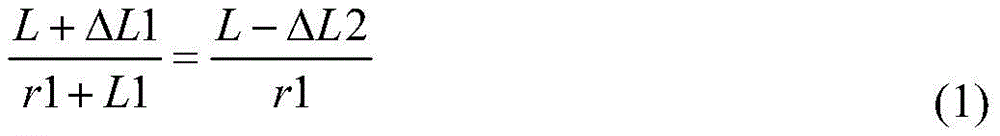
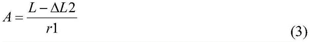
(2)第一卡盘和第二卡盘之间的距离为L,在Z-Y方向上,通过第一位移传感器和第二位移传感器测量出第一位移传感器和第二位移传感器的距离变化值ΔL1和ΔL2:(2) The distance between the first chuck and the second chuck is L, and in the Z-Y direction, the distance change value ΔL1 between the first displacement sensor and the second displacement sensor is measured by the first displacement sensor and the second displacement sensor and ΔL2:


式中CD即为所求的丝杠在Z方向的弯曲挠度ωz;In the formula, CD is the bending deflection ω z of the lead screw in the Z direction;
同样,根据X-Y方向上第三位移传感器和第四位移传感器的距离变化值ΔL3和ΔL4计算出丝杠在X方向的弯曲挠度ωx;Similarly, the bending deflection ω x of the lead screw in the X direction is calculated according to the distance change values ΔL3 and ΔL4 of the third displacement sensor and the fourth displacement sensor in the XY direction;
根据ωz和ωx进一步计算出丝杠的总弯曲挠度ω及其与X方向的夹角θ:According to ω z and ω x, the total bending deflection ω of the lead screw and its angle θ with the X direction are further calculated:


式中,r1为丝杠弯曲内圆距丝杠曲率中心的距离,A为丝杠长度局部长度L范围内丝杠弯曲的圆心角,L1为丝杠公称直径。In the formula, r1 is the distance from the inner circle of the lead screw to the center of curvature of the lead screw, A is the central angle of the lead screw within the local length L of the lead screw length, and L1 is the nominal diameter of the lead screw.
与现有技术相比,本发明的技术方案所带来的有益效果是:Compared with the prior art, the beneficial effects brought by the technical solution of the present invention are:
由于滚珠丝杠工作方式的特殊性,工作过程中滚珠丝杠的弯曲挠度不方便直接测出,本发明在现有检测丝杠弯曲挠度装置的基础上,将第一卡盘、第二卡盘设计为分离式,便于安装;并通过位移传感器的布局,提高了对应变的灵敏度,从而通过计算方法计算出弯曲挠度,检测装置的软件系统通过对位移传感器的测量数据处理,可实时评价出滚珠丝杠的弯曲挠度值,具有精度高,计算简单的优点,并且结果具有较高的可靠性。Due to the particularity of the working mode of the ball screw, it is inconvenient to directly measure the bending deflection of the ball screw during the working process. On the basis of the existing device for detecting the bending deflection of the ball screw, the present invention uses the first chuck, the second chuck It is designed as a separate type, which is easy to install; and through the layout of the displacement sensor, the sensitivity to strain is improved, so that the bending deflection is calculated by the calculation method, and the software system of the detection device can evaluate the ball in real time by processing the measurement data of the displacement sensor. The bending deflection value of the lead screw has the advantages of high precision and simple calculation, and the result has high reliability.
附图说明Description of drawings
图1a是本发明装置的三维结构示意图,图1b是本发明装置使用状态示意图。Fig. 1a is a schematic diagram of a three-dimensional structure of the device of the present invention, and Fig. 1b is a schematic view of the state of use of the device of the present invention.
图2a、2b和2c分别是具体实施例中第一卡盘的三维、二维及其侧视结构示意图。Figures 2a, 2b and 2c are respectively three-dimensional, two-dimensional and side view structural schematic diagrams of the first chuck in a specific embodiment.
图3a、3b和3c分别是具体实施例中第二卡盘的三维、二维及其侧视结构示意图。Figures 3a, 3b and 3c are respectively three-dimensional, two-dimensional and side view structural schematic diagrams of the second chuck in the specific embodiment.
图4是位移传感器的布置位置示意图。Fig. 4 is a schematic diagram of the arrangement position of the displacement sensor.
图5a和图5b均是丝杠弯曲挠度计算示意图。Figure 5a and Figure 5b are both schematic diagrams for calculating the bending deflection of the lead screw.
图6滚珠丝杠弯曲挠度检测流程图。Fig. 6 Flow chart of ball screw bending deflection detection.
图7针对本发明实施例检测装置配套的软件系统界面图。Fig. 7 is an interface diagram of the software system supporting the detection device according to the embodiment of the present invention.
附图标记:1-第一卡盘,2-第二卡盘,3-位移传感器,4-矩形齿槽,5-矩形齿牙Reference signs: 1-first chuck, 2-second chuck, 3-displacement sensor, 4-rectangular tooth groove, 5-rectangular tooth
具体实施方式Detailed ways
下面结合附图对本发明作进一步的描述:Below in conjunction with accompanying drawing, the present invention will be further described:
如图1a和1b所示,一种滚珠丝杠弯曲挠度检测装置,包括第一卡盘1和第二卡盘2,第一卡盘1和第二卡盘2通过紧固螺栓与丝杠螺母副相连,第一卡盘1和第二卡盘2中部相对应的设有用于穿设滚珠丝杠的连接孔,第一卡盘1上设有矩形齿槽4,第二卡盘2上设有与矩形齿槽4相契合的矩形齿牙5,连接孔的周围等间距的环绕设置有四个位移传感器3,本实施例中检测装置外形尺寸为φ100mm×42mm,矩形齿槽4和矩形齿牙5想接合形成矩形爪盘,防止应力测试柱在丝杠进给过程中产生扭转变形。具体实施过程中丝杠螺母之间还设有连接螺钉,连接螺钉起到力的传递作用,其中矩形齿槽4和矩形齿牙5承受大部分的扭矩,As shown in Figures 1a and 1b, a ball screw bending deflection detection device includes a
图2a是本实施例中第一卡盘的三维结构示意图,图2b和2c分别是其二维结构示意图和剖视结构示意图。Fig. 2a is a schematic three-dimensional structural diagram of the first chuck in this embodiment, and Figs. 2b and 2c are a schematic two-dimensional structural diagram and a schematic cross-sectional structural diagram respectively.
图3a是本实施例中第二卡盘的三维结构示意图,图3b和3c分别是其二维结构示意图和剖视结构示意图。Fig. 3a is a schematic diagram of a three-dimensional structure of the second chuck in this embodiment, and Figs. 3b and 3c are a schematic diagram of its two-dimensional structure and a schematic cross-sectional structure, respectively.
如图4所示,本实施例中第一卡盘1上均匀布置四个位移传感器3,分别为第一位移传感器、第二位移传感器、第三位移传感器和第四位移传感器。丝杠在运动过程中四个位移传感器会感受到两丝杠螺母之间的位置变化,将信号传递到采集其中,采集器读出传感器示数。本实施例中位移传感器3选用杰诺LM12-3004NA LM12-3004PA,其检测精度为0.1微米。当丝杠发生弯曲变形时四个位移传感器的示数会发生变化,根据传感器的示As shown in FIG. 4 , four
如图5a和图5b所示,已知两卡盘之间的距离为L。在Z-Y截面内,通过第一位移传感器和第二位移传感器可以测量出位移传感器的距离变化值ΔL1和ΔL2。As shown in Fig. 5a and Fig. 5b, the distance L between the two chucks is known. In the Z-Y section, the distance change values ΔL1 and ΔL2 of the displacement sensors can be measured by the first displacement sensor and the second displacement sensor.


式中CD即为所求的丝杠在z方向的弯曲挠度ωz。where CD is the desired bending deflection ω z of the lead screw in the z direction.
同样,根据X-Y方向上第三位移传感器和第四位移传感器的距离变化值ΔL3和ΔL4计算出X方向的弯曲挠度ωx;Similarly, the bending deflection ω x in the X direction is calculated according to the distance change values ΔL3 and ΔL4 of the third displacement sensor and the fourth displacement sensor in the XY direction;
根据计算出的ωz和ωx可以进一步计算出丝杠的总弯曲挠度ω及其与X向的夹角θ。According to the calculated ω z and ω x, the total bending deflection ω of the lead screw and its angle θ with the X direction can be further calculated.


根据图6滚珠丝杠弯曲挠度测试流程所示,需要开发一套完整的滚珠丝杠弯曲挠度检测装置软件系统必须能实现数据读入功能、方向选择功能、测试点筛选功能、弯曲变形量计算功能、弯曲图形绘制功能、弯曲量最大、最小值及弯曲度显示功能并且拥有良好的用户操作界面。According to the ball screw bending deflection test process shown in Figure 6, it is necessary to develop a complete set of ball screw bending deflection detection device software system must be able to realize the data reading function, direction selection function, test point screening function, bending deformation calculation function , Bending graphic drawing function, maximum bending value, minimum value and bending degree display function and has a good user interface.
所以具体实施过程中开发出了一款符合上述要求的滚珠丝杠弯曲挠度测试系统软件,用户界面如图7所示。Therefore, a ball screw bending deflection test system software that meets the above requirements has been developed during the specific implementation process. The user interface is shown in Figure 7.
本发明并不限于上文描述的实施方式。以上对具体实施方式的描述旨在描述和说明本发明的技术方案,上述的具体实施方式仅仅是示意性的,并不是限制性的。在不脱离本发明宗旨和权利要求所保护的范围情况下,本领域的普通技术人员在本发明的启示下还可做出很多形式的具体变换,这些均属于本发明的保护范围之内。The present invention is not limited to the embodiments described above. The above description of the specific embodiments is intended to describe and illustrate the technical solution of the present invention, and the above specific embodiments are only illustrative and not restrictive. Without departing from the gist of the present invention and the scope of protection of the claims, those skilled in the art can also make many specific changes under the inspiration of the present invention, and these all belong to the protection scope of the present invention.
Claims (1)


Priority Applications (1)
| Application Number | Priority Date | Filing Date | Title |
|---|---|---|---|
| CN201710112483.8A CN106871857B (en) | 2017-02-28 | 2017-02-28 | A device and method for detecting the bending deflection of a ball screw |
Applications Claiming Priority (1)
| Application Number | Priority Date | Filing Date | Title |
|---|---|---|---|
| CN201710112483.8A CN106871857B (en) | 2017-02-28 | 2017-02-28 | A device and method for detecting the bending deflection of a ball screw |
Publications (2)
| Publication Number | Publication Date |
|---|---|
| CN106871857A CN106871857A (en) | 2017-06-20 |
| CN106871857B true CN106871857B (en) | 2023-02-17 |
Family
ID=59169480
Family Applications (1)
| Application Number | Title | Priority Date | Filing Date |
|---|---|---|---|
| CN201710112483.8A Active CN106871857B (en) | 2017-02-28 | 2017-02-28 | A device and method for detecting the bending deflection of a ball screw |
Country Status (1)
| Country | Link |
|---|---|
| CN (1) | CN106871857B (en) |
Families Citing this family (1)
| Publication number | Priority date | Publication date | Assignee | Title |
|---|---|---|---|---|
| CN117890043B (en) * | 2024-03-15 | 2024-05-24 | 山东省汶上县丝杠有限责任公司 | Bending deflection detection device and method for ball screw |
Citations (12)
| Publication number | Priority date | Publication date | Assignee | Title |
|---|---|---|---|---|
| JPS61297058A (en) * | 1985-06-24 | 1986-12-27 | Seiko Epson Corp | positioning device |
| JPH0462450A (en) * | 1990-06-30 | 1992-02-27 | Kawatetsu Adobantetsuku Kk | Method and device for detecting abnormality of ball screw |
| JP2001349407A (en) * | 2000-06-08 | 2001-12-21 | Sumitomo Heavy Ind Ltd | Device for detecting abnormality of ball screw |
| CN101907441A (en) * | 2009-06-03 | 2010-12-08 | 上海莱恩精密机床附件有限公司 | Laser Pitch Measuring Instrument for Ball Screw and Its Measuring Method |
| JP2011122906A (en) * | 2009-12-10 | 2011-06-23 | Jtekt Corp | Torque measuring method and device of ball screw |
| CN102152799A (en) * | 2011-03-18 | 2011-08-17 | 南京南车浦镇城轨车辆有限责任公司 | Presetting and detecting device for vehicle deflections of metro vehicles and use method of same |
| CN102331376A (en) * | 2011-06-24 | 2012-01-25 | 赵宏伟 | Cross-scale micro-nano in-situ three-point bending mechanical performance testing platform |
| CN102735206A (en) * | 2012-05-31 | 2012-10-17 | 武汉理工大学 | Dynamic rotary kiln supporting roller shaft deflection variation and cylinder bending measuring method and instrument |
| CN202709987U (en) * | 2012-05-03 | 2013-01-30 | 张领先 | Bridge deflection monitoring device |
| CN103868470A (en) * | 2014-03-10 | 2014-06-18 | 中国地质大学(武汉) | Curvature detection device and method for drill rod |
| CN103926077A (en) * | 2014-04-24 | 2014-07-16 | 清华大学 | Comprehensive measuring device of static and dynamic rigidity of ball screw |
| CN206601119U (en) * | 2017-02-28 | 2017-10-31 | 天津大学 | A kind of ball-screw sag detection means |
Family Cites Families (2)
| Publication number | Priority date | Publication date | Assignee | Title |
|---|---|---|---|---|
| CN103018104B (en) * | 2012-12-26 | 2015-04-22 | 南京理工大学 | Horizontal measuring device for axial static rigidity of ball screw pair and method thereof |
| CN205184300U (en) * | 2015-12-01 | 2016-04-27 | 天津中屹铭科技有限公司 | Take work piece to go up and down and control automatic centering mechanism of removal with centering chuck |
-
2017
- 2017-02-28 CN CN201710112483.8A patent/CN106871857B/en active Active
Patent Citations (12)
| Publication number | Priority date | Publication date | Assignee | Title |
|---|---|---|---|---|
| JPS61297058A (en) * | 1985-06-24 | 1986-12-27 | Seiko Epson Corp | positioning device |
| JPH0462450A (en) * | 1990-06-30 | 1992-02-27 | Kawatetsu Adobantetsuku Kk | Method and device for detecting abnormality of ball screw |
| JP2001349407A (en) * | 2000-06-08 | 2001-12-21 | Sumitomo Heavy Ind Ltd | Device for detecting abnormality of ball screw |
| CN101907441A (en) * | 2009-06-03 | 2010-12-08 | 上海莱恩精密机床附件有限公司 | Laser Pitch Measuring Instrument for Ball Screw and Its Measuring Method |
| JP2011122906A (en) * | 2009-12-10 | 2011-06-23 | Jtekt Corp | Torque measuring method and device of ball screw |
| CN102152799A (en) * | 2011-03-18 | 2011-08-17 | 南京南车浦镇城轨车辆有限责任公司 | Presetting and detecting device for vehicle deflections of metro vehicles and use method of same |
| CN102331376A (en) * | 2011-06-24 | 2012-01-25 | 赵宏伟 | Cross-scale micro-nano in-situ three-point bending mechanical performance testing platform |
| CN202709987U (en) * | 2012-05-03 | 2013-01-30 | 张领先 | Bridge deflection monitoring device |
| CN102735206A (en) * | 2012-05-31 | 2012-10-17 | 武汉理工大学 | Dynamic rotary kiln supporting roller shaft deflection variation and cylinder bending measuring method and instrument |
| CN103868470A (en) * | 2014-03-10 | 2014-06-18 | 中国地质大学(武汉) | Curvature detection device and method for drill rod |
| CN103926077A (en) * | 2014-04-24 | 2014-07-16 | 清华大学 | Comprehensive measuring device of static and dynamic rigidity of ball screw |
| CN206601119U (en) * | 2017-02-28 | 2017-10-31 | 天津大学 | A kind of ball-screw sag detection means |
Non-Patent Citations (1)
| Title |
|---|
| 滚珠丝杠副的弯曲变形对传动精度的影响分析;万玉;《机械工程师》;20091130(第11期);第112-113页 * |
Also Published As
| Publication number | Publication date |
|---|---|
| CN106871857A (en) | 2017-06-20 |
Similar Documents
| Publication | Publication Date | Title |
|---|---|---|
| US20160273979A1 (en) | Residual stress measuring method | |
| JP2006098392A (en) | Angle detector with self-calibration function | |
| CN104198303B (en) | Device for measuring creep of torsion bar | |
| CN102607433A (en) | Multi-point detection device for thickness of bearing bush | |
| US8904884B2 (en) | Torque sensor | |
| CN105675329B (en) | A kind of static rigidity of lathe measuring device | |
| WO1998014750A1 (en) | Gauge for measuring large diameter | |
| CN106644320B (en) | A kind of ball-screw bending deflection detection device and its detection method | |
| CN102003931B (en) | Comprehensive detection method and device of tool tapered handle (7:24) | |
| CN103743508B (en) | Torsional moment test macro and torque sensor device thereof | |
| CN206161218U (en) | Action roller tension sensor of measurable atress angle | |
| CN106092014A (en) | For measuring the radial dimension of multipoint measuring instrument of thin-wall bearing and measuring method | |
| CN204963740U (en) | Inner diameter measurement device | |
| JP7286512B2 (en) | test indicator | |
| CN106871857B (en) | A device and method for detecting the bending deflection of a ball screw | |
| CN109458915A (en) | A kind of detecting tool and detection method of profile of plate cam | |
| CN200986478Y (en) | Ball guide-screw pair frictional moment measuring apparatus | |
| CN206601119U (en) | A kind of ball-screw sag detection means | |
| CN112284241A (en) | A strain pressure sensor | |
| CN104931176B (en) | A kind of piezoelectric type scroll chuck clamps force measuring device | |
| CN108225622B (en) | A three-dimensional force sensor | |
| CN210486742U (en) | End face ring groove combined gauge | |
| CN108061503B (en) | Method for detecting outer diameter of conical part on length measuring instrument | |
| US9651439B2 (en) | Axial force testing device for spindles of machines | |
| CN217465649U (en) | A thread phase angle detection structure |
Legal Events
| Date | Code | Title | Description |
|---|---|---|---|
| PB01 | Publication | ||
| PB01 | Publication | ||
| SE01 | Entry into force of request for substantive examination | ||
| SE01 | Entry into force of request for substantive examination | ||
| GR01 | Patent grant | ||
| GR01 | Patent grant |