CN106780618B - Three-dimensional information acquisition method and device based on heterogeneous depth camera - Google Patents
Three-dimensional information acquisition method and device based on heterogeneous depth camera Download PDFInfo
- Publication number
- CN106780618B CN106780618B CN201611050176.3A CN201611050176A CN106780618B CN 106780618 B CN106780618 B CN 106780618B CN 201611050176 A CN201611050176 A CN 201611050176A CN 106780618 B CN106780618 B CN 106780618B
- Authority
- CN
- China
- Prior art keywords
- camera
- depth
- point
- information
- kinect
- Prior art date
- Legal status (The legal status is an assumption and is not a legal conclusion. Google has not performed a legal analysis and makes no representation as to the accuracy of the status listed.)
- Expired - Fee Related
Links
Images


Classifications
-
- G—PHYSICS
- G06—COMPUTING OR CALCULATING; COUNTING
- G06T—IMAGE DATA PROCESSING OR GENERATION, IN GENERAL
- G06T2207/00—Indexing scheme for image analysis or image enhancement
- G06T2207/10—Image acquisition modality
- G06T2207/10024—Color image
-
- G—PHYSICS
- G06—COMPUTING OR CALCULATING; COUNTING
- G06T—IMAGE DATA PROCESSING OR GENERATION, IN GENERAL
- G06T2207/00—Indexing scheme for image analysis or image enhancement
- G06T2207/10—Image acquisition modality
- G06T2207/10028—Range image; Depth image; 3D point clouds
Landscapes
- Image Processing (AREA)
- Length Measuring Devices By Optical Means (AREA)
Abstract
The invention discloses a three-dimensional information acquisition method based on a heterogeneous depth camera, which comprises the following steps: shooting a picture; obtaining internal parameters of a Kinect camera and a TOF camera; extracting reliable depth information according to the shot picture; respectively fitting respective calibration plate plane coordinates according to the reliable depth information; restoring the actual three-dimensional coordinate sets of the corner points of the Kinect camera and the TOF camera under the respectively fitted calibration plate plane coordinates by combining the internal parameters; solving a least square conversion matrix between the two; performing coordinate conversion on the reliable depth information according to the least square conversion matrix to obtain depth fusion information; matching color information acquired by the Kinect camera with depth fusion information; and carrying out point cloud registration on the matched image information based on the space distance between the points to obtain three-dimensional information. By adopting the method and the device, the high-resolution accurate depth map fusing the color information can be rapidly acquired, and accurate three-dimensional information can be further acquired.
Description
Technical Field
The invention belongs to the field of image processing and point cloud registration, and particularly relates to a three-dimensional information acquisition method and device based on a heterogeneous depth camera.
Background
At present, two approaches for acquiring depth information of an object mainly include a stereo matching method and a depth camera method for acquiring depth by solving parallax of image matching points. Among them, the widely used depth cameras are mainly a Kinect camera (Kinect XBOX360 of microsoft corporation, the same below) using a structured light technology and a TOF camera (represented by SR4000 of Mesa corporation) using a Time of flight (Time of flight) technology. The TOF camera can generate a depth map in real time, has high depth information precision, can support hardware triggering, and has low image resolution. For example, the accuracy of the depth information obtained by the SR4000 camera of the Mesa corporation can be controlled within 1cm, but the maximum image resolution is only 176 × 144. A Kinect camera using structured light techniques can generate high resolution depth maps (depth map resolution is at most 640 x 480), but the reliability of the depth information is low (depth information accuracy is within 10 cm).
In the fields of reverse engineering, stereo television, pattern recognition based on depth information and the like, the appearance of high-resolution accurate depth maps greatly reduces the technical difficulty of related algorithms. However, as can be seen from the above, a high-resolution accurate depth map cannot be acquired by only the TOF camera or the Kinect camera alone.
The existing solution at home and abroad is as follows: and fusing the depth information obtained by the depth camera with the depth information obtained by stereo matching to obtain a high-resolution accurate depth map. The depth information obtained by stereo matching needs to be calibrated by a camera, and depth data is further calculated by using an algorithm such as confidence coefficient propagation, and the calculation process consumes time and resources. Meanwhile, the calibration between some depth cameras and ordinary color cameras needs to be carried out by means of accurate machinery, so that the calibration is carried out according to the motion trail, and the use conditions and the use occasions are greatly increased. The application discloses that a color camera array is directly used in calibration, as chinese patent publication No. CN101556696, published as 2009, 10, 14, and named as an array camera-based depth map real-time acquisition algorithm. The disadvantages are that: common color cameras are very affected by illumination and texture, thus resulting in poor operability of direct calibration of color cameras with TOF depth cameras.
Therefore, to acquire complete three-dimensional information of an object, after depth information (point cloud) at a certain viewing angle is acquired, depth data at different viewing angles need to be registered, and the process is called three-dimensional point cloud registration of the object. Most of the current coarse registration algorithms use RANSAC and feature value combination methods, such as the coplanar four-point set algorithm proposed by the driver Aiger (from Aiger D, Mitra N J, Cohen-Or D.4-points consistency sets for robust pair surface registration [ C ]// ACM Transformations On Graphics (TOG); ACM,2008,27(3): 85). In 2014, Mellado Nicolas improved the driver Aiger algorithm and proposed the super 4pcs algorithm (from Mellado N, Aiger D, Mitra N J. super 4pcs fast glass spherical porous registered geometric index [ C ]// Computer Graphics Forum.2014,33(5):205 and 215.), and the number of similar control sets was reduced by restricting the angle range between the diagonals of the target quadrangle. Nevertheless, the accuracy of the similar control sets found only by means of geometric features is still difficult to guarantee, and the number of control sets is also very large.
Disclosure of Invention
In order to solve the above problems, an object of the present invention is to provide a three-dimensional information obtaining method based on a heterogeneous depth camera, which can obtain a high-resolution accurate depth map fused with color information, and further obtain accurate three-dimensional information.
In order to achieve the purpose, the invention is realized according to the following technical scheme:
the invention discloses a three-dimensional information acquisition method based on a heterogeneous depth camera, which comprises the following steps:
s1, in the common shooting visual field, the calibration plate is placed at least at 10 different positions, and at least 1 picture is shot at each position by using a Kinect camera and a TOF camera respectively;
s2, respectively obtaining internal parameters of the Kinect camera and the TOF camera according to pictures shot by the Kinect camera and the TOF camera respectively Wherein α ═ f/dx, β ═ f/dy, f is the focal length of the camera, dx represents the width of one pixel in the x-axis direction, and dy represents the width of one pixel in the y-axis direction; (u)0,ν0) The principal point, called the image plane, is also an intrinsic parameter of the camera; and gamma represents the deviation of the pixel point in the x and y directions.
S3, according to the shot picture and the formula The reliable depth information is extracted and,
d represents depth information, reliable depth information is represented when D is reliable, and unreliable depth information is represented when D is nonreable; i represents the intensity value, T represents the threshold value T obtained by Otsu method;
s4, respectively fitting respective calibration plate plane coordinates to the Kinect camera and the TOF camera according to the reliable depth information;
s5, restoring the actual three-dimensional coordinate sets of the corner points of the Kinect camera and the TOF camera under the respectively fitted calibration plate plane coordinates by combining the internal parameters;
s6, solving a least square conversion matrix between the Kinect camera and the TOF camera according to the actual three-dimensional coordinate sets of the corner points of the Kinect camera and the TOF camera;
s7, performing coordinate conversion on the reliable depth information acquired by the Kinect camera and the TOF camera according to the least square conversion matrix to obtain depth fusion information;
s8, matching color information acquired by the Kinect camera with depth fusion information;
and S9, carrying out point cloud registration on the matched image information based on the space distance between the points to obtain three-dimensional information.
Further, the step of S9 specifically includes:
selecting a source control set from a source data set P;
selecting a color similarity control set according to the source control set in the target data set Q;
performing ICP (inductively coupled plasma) criterion on the source control set and the color similarity control set to obtain an optimal transformation matrix, and splicing point clouds in the source data set P and the target data set Q by using the optimal transformation matrix to obtain three-dimensional information;
wherein the source data set P and the target data set Q are depth data information under different viewing angles.
Further, the step of S91 is specifically:
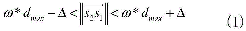
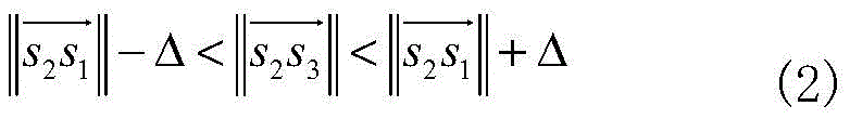
randomly extracting four coplanar points s in the source data set P1,s2,s3,s4In which { s }1,s2,s3,s4Satisfy:


wherein, the overlapping rate between the two data models P and Q is omega, and the average point cloud spacing d of the source data set PavgMaximum point cloud distance dmaxAnd a distance threshold Δ davg*0.1;
Finding a straight line s1s3And s2s4Approximate intersection e ofsThus obtaining a coplanar five-point set Fs={s1,s2,s3,s4,es};
The coplanar five-point set is expressed by the following four characteristic values of the coplanar five-point set:
diagonal single ratio Diagonal
 single ratio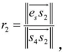
③ included angle between two adjacent sides ④FsColor vector of color value corresponding to each point in RGB color space:
coplanar five-point set FsAnd its corresponding color control set CsCommon component source control set S ═ { F ═ Fs,Cs}。
Further, the step of S92 is specifically:
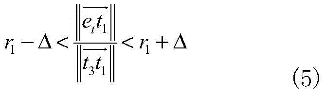
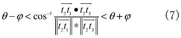
searching a coplanar five-point set F with all characteristic values satisfying equations (5) - (8) in a target data set Qt={t1,t2,t3,t4,et};


DC≤C (8)
Wherein Representing an angle error threshold between the coplanar five-point sets;
etaccording to coplanar quadrilaterals t1t2t3t4Recalculating the intersection point;
DCis CsAnd CtThe color difference therebetween;
c is the measurement of the color difference between the source control set and the similar control set by the point cloud color distance threshold;
each coplanar five-point set in the similar control set has a corresponding color vector set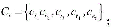
All C satisfying the formula (8)tCoplanar five-point set F corresponding to the sametForming color similarity control set T ═ T1,T2,...,Tn}。
Further, the step of S93 is specifically:
controlling the color similarity to a set Ti={T1,i,T2,i,...,Tm,i,.. } and source control set Si={Fs,i,Cs,iSolving a rotation matrix R by using a least square methodm,iAnd a translation matrix tm,i(ii) a Wherein m represents one of the color similarity control sets; i represents the number of times;
is derived from the conversion relation p'm,i=Rm,i*p+tm,iTransforming a point P in the source data set P to the coordinate of the target set Q;
finding p 'in target set Q'm,iPoint of minimum distanceFrom this point to p'm,iIs p'm,iEuclidean distance d (p ') from target point set Q'm,i,Q);
If d (p'm,iQ) is less than or equal to delta, then the point p is in the maximum consistent set, LCPm,iThe number of (2) is increased by 1;
LCPm,iwhen the number is maximum, the corresponding rotation matrix Rm,iAnd a translation matrix tm,iIs an optimal transformation matrix;
and splicing point clouds in the source data set P and the target data set Q corresponding to the optimal transformation matrix to obtain three-dimensional information.
Further, the step of S4 is specifically:
three-dimensional coordinates (x) of corner pointsd,yd,zd)
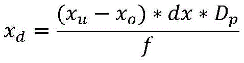

zd=Dp
Wherein (x)o,yo) As the projection point of the optical center on the image, dx, dy is the pixel pitch of the Kinect camera 1, DpFitting a plane equation by using the three-dimensional coordinates of the angular points, wherein the depth value is corresponding to the Kinect camera 1, and the focal length is f;
assuming that the plane equation is aX + bY + cZ ═ d (9), the optimal equation coefficients a, b, c, and d can be obtained bY the least square method, and the plane can be fitted.
Further, the step of S5 is specifically:
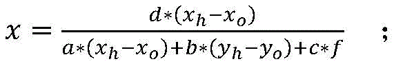
suppose a certain point corner point H on the image coordinates, whose image coordinates are (x)h,yh),(xo,yo) Is the projection point of the optical center on the image, dx and dy are the pixel distances between the corner point H and the Kinect camera and the TOF camera, DhAnd f, the straight line equation of the line connecting the optical center and the point H is as follows:

the intersection point of the linear equation and the plane equation is the actual three-dimensional coordinate of the corner point;
from the above equations (9) and (10), the actual three-dimensional coordinates of the intersection point (x, y, z) are found as:


so far, the actual three-dimensional coordinate set H of all corner points is obtained1={h1,h2,…hnLike this, the actual three-dimensional coordinate set H of the corner point obtained by another camera2={h1,h2,…hn}。
Further, the step of S6 is specifically:
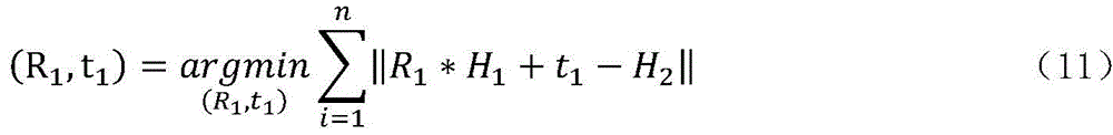
solving a least squares transformation matrix (R) between a depth dataset T of a TOF camera and a depth dataset K of a Kinect camera1,t1) Namely:
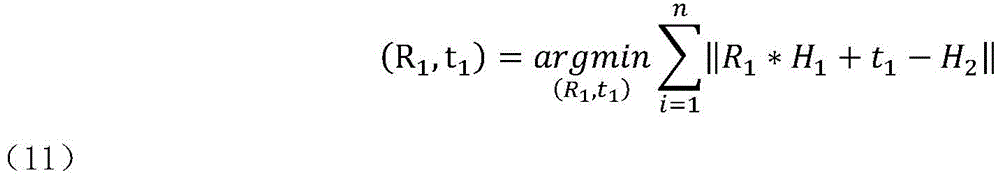
where n is a positive integer representing the number of corner points.
The three-dimensional information acquisition device based on the heterogeneous depth camera comprises a processor, a Kinect camera and a TOF camera, wherein the Kinect camera and the TOF camera are respectively connected with the processor; the Kinect camera and the TOF camera transmit acquired depth image information to the processor, and the processor matches low-resolution high-precision depth image information in the depth image information with high-resolution low-precision depth image information to obtain a high-resolution high-precision depth map.
Further, the Kinect camera comprises an infrared emitter, a color camera and a depth camera, wherein the infrared emitter is used for emitting an infrared band light source, the color camera is used for collecting color image information, and the depth camera is used for collecting depth image information; and the processor matches the color image information with the depth image information, and performs point cloud registration to acquire three-dimensional information.
Compared with the prior art, the invention has the beneficial effects that:
the invention relates to a heterogeneous camera system based on the combination of design TOF sensors and structured light Kinect sensors, and provides a camera calibration method based on depth information. The system can combine the depth information of the two, and then acquire a high-resolution accurate depth map by matching the low-resolution depth map into the high-resolution depth map.
Meanwhile, the Kinect camera is a fixed system comprising a color camera and a depth camera, and the Kinect camera is provided with a method for calibrating the two cameras, so that the depth camera of the Kinect is used as an intermediate, data of the color camera is matched into depth data of the TOF camera, internal reference is obtained, reliable depth information is extracted, plane coordinates of a calibration plate are fitted, an angular point three-dimensional coordinate set is recovered, a least square conversion matrix is obtained, fusion of color information and depth information and point cloud registration operation are carried out, and finally a high-resolution accurate depth map is obtained.
Specifically, the three-dimensional information acquisition method and device based on the heterogeneous depth camera have the following characteristics:
1. according to the three-dimensional information acquisition method based on the heterogeneous depth camera, the calculated amount is small in the process of matching the color data information and the depth data information, and extra mechanical equipment is not needed for calibrating the cameras;
2. compared with the existing similar algorithm, the three-dimensional information acquisition method based on the heterogeneous depth camera improves the registration accuracy and reduces the calculated amount;
3. the calibration method in the three-dimensional information acquisition method based on the heterogeneous depth camera is simple and only needs one calibration;
4. the traditional stereo matching method is influenced by textures and illumination intensity, and the Kinect camera in the three-dimensional information acquisition device based on the heterogeneous depth camera has a light source emitting in an infrared band, so that the Kinect camera is basically not influenced by illumination;
5. due to the low price of the Kinect camera, compared with the prior system that the TOF camera is combined with a plurality of common color CCD cameras, the TOF camera and the Kinect camera system have higher cost performance.
Drawings
Embodiments of the invention are described in further detail below with reference to the attached drawing figures, wherein:
FIG. 1 is a schematic flow chart of a three-dimensional information acquisition method based on a heterogeneous depth camera according to the present invention;
FIG. 2 is a schematic flow chart of a point cloud registration step in the three-dimensional information acquisition method based on the heterogeneous depth camera according to the present invention;
fig. 3 is a schematic structural diagram of three-dimensional information acquisition based on heterogeneous depth cameras according to the present invention.
In the figure:
1: kinect camera
11: the infrared emitter 12: color camera 13: depth camera
2: TOF camera
3: processor with a memory having a plurality of memory cells
Detailed Description
The preferred embodiments of the present invention will be described in conjunction with the accompanying drawings, and it will be understood that they are described herein for the purpose of illustration and explanation and not limitation.
As shown in fig. 1 to 3, in the three-dimensional information acquisition method based on the heterogeneous depth camera, under the condition that the resolution of the depth map of the Kinect camera is not changed, the reliability of the depth information of the Kinect camera is improved by using the accurate depth map acquired by the TOF camera, so that the accurate depth map with high resolution is acquired.
In the process of obtaining a high-resolution accurate depth map, aiming at the problems that the registration speed is low due to excessive redundant control sets in the existing three-dimensional point cloud global registration process, and the registration accuracy is difficult to guarantee due to improper selection of the control sets, the concept of color coplanar five-point set and point cloud color distance is introduced, and the three-dimensional point cloud automatic registration algorithm based on the color distance between the points is provided.
In order to achieve the purpose, the three-dimensional information acquisition device based on the heterogeneous depth cameras adopts one Kinect camera 1 and one TOF camera 2, namely two depth cameras are designed to acquire image information with characteristics respectively, the Kinect camera 1 has high resolution, and the TOF camera 2 has high depth information precision. And then, calibrating through the processor 3, and obtaining a high-resolution accurate depth map after fusion. Meanwhile, the method of matching the color information collected by the color camera 12 to the depth information is combined with the point cloud registration algorithm of the color information to jointly complete the acquisition of the three-dimensional information of the object.
In the embodiment of the present invention, the structured light depth Kinect camera 1 adopts Kinect XBOX360 of microsoft corporation, and the camera can provide a depth map with the highest resolution of 640 × 480 and a color map with the highest resolution of 1280 × 960; the TOF camera 2, which uses the SR4000 from the company MESA, can provide depth and intensity maps (grey scale maps) with a resolution of 176 × 144, and the modulation frequencies can be 29MHZ, 30MHZ, and 31 MHZ.
As shown in fig. 1, the method for acquiring three-dimensional information based on a heterogeneous depth camera according to the present invention includes the following steps:
s1: acquiring a depth map: in the common shooting visual field, the calibration plate is placed at least at 10 different positions, and at least 1 picture is shot at each position by using a Kinect camera 1 and a TOF camera 2 respectively;
s2: respectively obtaining internal parameters of the Kinect camera 1 and the TOF camera 2 according to the picture shot in the step S1;
wherein the resolution of the depth map and the color map of the Kinect camera 1 are both 320 × 240; in order not to interfere with the structured light emitted by the Kinect camera 1, the optical frequency of SR4000 selected by the TOF camera 2 is set to 31 MHZ.
The method for solving the internal parameters of the Kinect camera 1 is the same as that of the TOF camera 2, and the solution of the Kinect camera is only specifically described here as follows:
the Kinect camera 1 takes a picture of the calibration plate according to step S1, and places the calibration plate in at least 10 different positions, each position taking a picture, and the position range of the calibration plate should cover the entire camera field of view as comprehensively as possible. The calibration board is a chessboard with calibration on the front surface, and each chessboard is a square with the side length of 31.4 mm.
In this embodiment, the calibration plate is placed at 10 different positions, and at each different position, the Kinect camera 1 is used to collect information 1 time for the calibration plate. Finally, 10 pieces of depth map and color map generated by the Kinect camera 1 (10 pieces of depth map and intensity map generated by the TOF camera 2, namely SR 4000) are acquired.
Then, self-calibrating the Kinect Camera 1 and the TOF Camera 2 by using a Camera imager carried by Matlab, specifically:
selecting a group of 10 depth maps acquired by a Kinect Camera 1 as input, and then manually inputting the side length of a checkerboard in a calibration board, wherein a Camera calibretter can automatically detect Harris angular points in an intensity map and can calculate internal parameters A of the Camera and external parameters (R, t) corresponding to each image, and the specific expression of A is as follows:
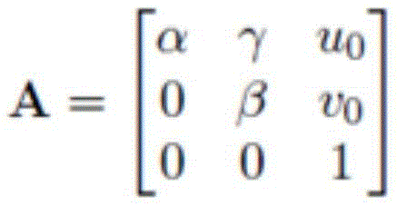
where α ═ f/dx, β ═ f/dy, and f is the focal length of the camera, because the pixels are not squares of the regular moment, dx represents the width of one pixel in the x-axis direction, and dy represents the width of one pixel in the y-axis direction; (u)0,ν0) Called principal of the image planePoints, which are also intrinsic parameters of the camera; and gamma represents the deviation of the pixel point in the x and y directions.
The relationship of the image coordinate system, the camera coordinate system and the three-dimensional coordinate system is expressed by the following expressions:

wherein Representing homogeneous coordinates (u, v,1) of pixels in the image coordinate system,
 homogeneous coordinates (X, Y, Z,1) representing the midpoint of a three-dimensional coordinate system, R representing a rotation matrix, t representing a translation matrix, S representing a scale factor, and A representing an intrinsic parameter of the camera.
S3: from the picture taken in step S1, information whose depth value is reliable is selected by the following formula:
performing threshold processing on the shot image, and then taking the inverse to obtain all points with reliable depth values on the calibration plate;
the following formula is utilized:

d represents depth information, reliable depth information is represented when D is reliable, and unreliable depth information is represented when D is nonreable; i represents the intensity value and T represents the threshold value T determined by the tsu method.
S4: according to the reliable depth information, respectively fitting respective calibration plate plane coordinates to a Kinect camera and a TOF camera;
the method for fitting the Kinect camera and the TOF camera is the same, and only the Kinect camera is taken as an example, and the method specifically comprises the following steps:
due to the influence of noise and the accuracy of the depth camera, each point which should be on the same plane originally hasSlight deviation, in order to find the truest depth value, combine to remove the points with unreliable depth value in S3, and then use the depth D of the remaining corner pointspThree-dimensional coordinates (x) of available corner pointsd,yd,zd)


zd=Dp
Wherein (x)o,yo) As the projection point of the optical center on the image, dx, dy is the pixel pitch of the Kinect camera 1, DpAnd f, fitting a plane equation by using the three-dimensional coordinates of the corner points, wherein the depth value corresponds to the Kinect camera 1 and the focal length is f.
Assuming that the plane equation is aX + bY + cZ ═ d, the optimal equation coefficients a, b, c, and d can be obtained bY the least square method, and the plane can be fitted.
S5: restoring the actual three-dimensional coordinate sets of the corner points of the Kinect camera and the TOF camera under the respectively fitted calibration plate plane coordinates by combining the internal parameters;
similarly, the same method for recovering the Kinect camera and the TOF camera is only taken as an example, and the steps are also specifically as follows:
and (3) solving the actual three-dimensional coordinates of the corner points:
assuming a certain point corner point H on the image coordinates, the equation of the straight line connecting the optical center and the point H is as follows:
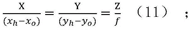
wherein: the image coordinate of the H point is (x)h,yh),(xo,yo) As the projection point of the optical center on the image, dx, dy is the pixel pitch of the Kinect camera 1, DhIs its corresponding depth value and the focal length of the camera is f.
The line equation and the plane equation of the calibration plate obtained in step S4 find an intersection approximate solution, and then obtain the actual three-dimensional coordinates of the corner point H:


so far, the actual three-dimensional coordinate set H of all corner points is obtained1={h1,h2,…hnLike this, the actual three-dimensional coordinate set H of the corner point obtained by another camera2={h1,h2,…hn}。
S6: according to the actual three-dimensional coordinate sets of the corner points of the Kinect camera and the TOF camera, solving a least square conversion matrix between the Kinect camera and the TOF camera;
solving a least square conversion matrix (R) between the depth data set T of the TOF camera 2 and the depth data set K of the Kinect camera 1 by utilizing a SVD singular value solving method1,t1). Namely:
wherein n is a positive integer and represents the number of corner points;
s7: and performing coordinate conversion on the reliable depth information acquired by the Kinect camera and the TOF camera according to the least square conversion matrix.
To this end, the depth data of the TOF camera 2 with the SR400 completed passes through the conversion matrix (R)1,t1) Projected into the depth data obtained by the Kinect camera 1. Namely:
TK=R1*T+t1
TKnamely Kinect camera shootingDepth data of TOF camera 2 in the field of view of camera 1.
S8: matching color information acquired by the Kinect camera with depth fusion information to realize the fusion of the depth information and the color information;
the matching between the data obtained by the color camera 12 built in the Kinect camera 1 and the depth camera 13 can be performed by using the Kinect SDK for Windows of microsoft corporation, assuming that the matrix from the color camera 12 to the depth data obtained by using the tool is (R)2,t2) The set of coordinate points in the color camera 12 is C ═ C1,c2,…cnK ═ a set of coordinate points in the depth camera 131,k2,…knThe set of coordinate points in the TOF camera 2 is F ═ F1,f2,…fnAnd then the color data is fused with the depth data information of the TOF by the following formula:
FK=R1*F+t1
CK=R2*C+t2
wherein C isKData for the color camera 12 in the field of view of the depth camera 13, FKIs the depth data of the TOF camera 2 in the field of view of the depth camera 13.
S9: and carrying out point cloud registration on the matched image information based on the space distance between the points to obtain three-dimensional information.
The method specifically comprises the following steps:
s91: selecting a source control set from a source data set P;
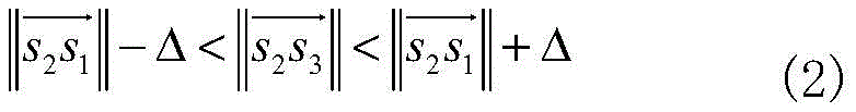
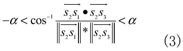
randomly extracting four coplanar points s in the source data set P1,s2,s3,s4In which { s }1,s2,s3,s4Satisfy:

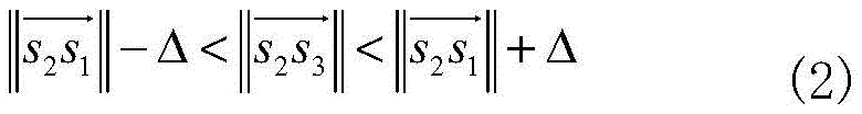
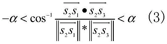

wherein, the overlapping ratio between the source data set P and the target data set Q is omega, and the average point cloud distance d of the source data set PavgMaximum point cloud distance dmaxAnd a distance threshold Δ davg*0.1;
Finding a straight line s1s3And s2s4Approximate intersection e ofsThus, a coplanar five-point set F is obtaineds={s1,s2,s3,s4,es};
The coplanar five-point set is expressed by the following four characteristic values of the coplanar five-point set:
diagonal single ratio Diagonal
 single ratio
③ included angle between two adjacent sides ④FsColor vector of color value corresponding to each point in RGB color space
 Coplanar five-point set FsAnd its corresponding color control set CsCommon component source control set S ═ { F ═ Fs,Cs}。
S92: selecting a color similarity control set;
searching a coplanar five-point set F with all characteristic values satisfying equations (5) - (8) in a target data set Qt={t1,t2,t3,t4,et}:

DC≤C (8)
Wherein Representing an angle error threshold between the coplanar five-point sets;
etaccording to coplanar quadrilaterals t1t2t3t4Recalculating the intersection point;
DCis CsAnd CtThe color difference therebetween;
each coplanar five-point set in the similar control set has a corresponding color vector set Wherein C is the point cloud color distance threshold which is a measure of the color difference between the source control set and the similar control set.
All C satisfying the formula (8)tCoplanar five-point set F corresponding to the sametForm similar control set T ═ T1,T2,...,Tn} (e.g. T1={Ft,1,Ct,1}, and so on).
It should be noted that: each source control set generally corresponds to a plurality of similar control sets, and the nearest neighbor problem in the process of selecting the similar control sets is solved by using K-d tree acceleration, so that the number of the control sets is reduced, and the time complexity of an algorithm is reduced.
S93: performing ICP (inductively coupled plasma) criterion on the source control set and the color similarity control set to obtain an optimal transformation matrix, and splicing point clouds in the source data set P and the target data set Q by using the optimal transformation matrix to obtain three-dimensional information; the LCP is a maximum consistent set, and refers to a set of points that can satisfy a certain condition within a certain error range.
Controlling the color similarity to a set Ti={T1,i,T2,i,...,Tm,i,.. } and source control set Si={Fs,i,Cs,iSolving a rotation matrix R by using a least square methodm,iAnd a translation matrix tm,i(ii) a Wherein m represents one of the color similarity control sets; i represents the number of times;
is derived from the conversion relation p'm,i=Rm,i*p+tm,iTransforming a point P in the source data set P to the coordinate of the target set Q;
finding p 'in target set Q'm,iPoint of minimum distance, this point and p'm,iIs p'm,iEuclidean distance d (p ') from target point set Q'm,i,Q);
If d (p'm,iQ) is less than or equal to delta, then the point p is in the maximum consistent set, LCPm,iThe number of (2) is increased by 1;
LCPm,iwhen the number is maximum, the corresponding rotation matrix Rm,iAnd a translation matrix tm,iAnd splicing the data in the source data set P and the target data set Q corresponding to the optimal change matrix to obtain three-dimensional information.
The three-dimensional information acquisition device based on the heterogeneous depth camera comprises a processor 3, and a Kinect camera 1 and a TOF camera 2 which are respectively connected with the processor 3, wherein the Kinect camera 1 and the TOF camera 2 transmit acquired depth image information to the processor 3, and the processor 3 matches low-resolution high-precision depth image information in the depth image information to high-resolution low-precision depth image information to acquire a high-resolution high-precision depth map.
Specifically, the Kinect camera 1 comprises an infrared emitter 11 for emitting an infrared band light source, a color camera 12 for collecting color image information and a depth camera 13 for collecting depth image information, which are respectively connected with the processor 3; the processor 3 matches the color image information to depth image information, and performs point cloud registration to acquire three-dimensional information.
The infrared emitter 11 can provide a required infrared band, and the problem that the existing matching method is easily affected by textures and illumination intensity is avoided.
Meanwhile, for the whole three-dimensional information acquisition device based on the heterogeneous depth camera, data of 3 cameras (the color camera 12, the depth camera 13 and the camera of the TOF camera 2) are actually adopted, but since the positions of the color camera 12 and the depth camera 13 are fixed, the depth information between the Kinect camera 1 and the TOF camera 2 only needs to be calibrated once, and the whole operation is relatively simpler.
Meanwhile, other contents of the three-dimensional information acquisition method and the three-dimensional information acquisition device based on the heterogeneous depth camera of the invention are referred to in the prior art and are not described herein again.
The above description is only a preferred embodiment of the present invention, and is not intended to limit the present invention in any way, so that any modification, equivalent change and modification made to the above embodiment according to the technical spirit of the present invention are within the scope of the technical solution of the present invention.
Claims (6)
1. A three-dimensional information acquisition method based on a heterogeneous depth camera is characterized by comprising the following steps:
s1, in the common shooting visual field, the calibration plate is placed at least at 10 different positions, and at least 1 picture is shot at each position by using a Kinect camera and a TOF camera respectively;
s2, respectively obtaining internal parameters of the Kinect camera and the TOF camera according to pictures shot by the Kinect camera and the TOF camera respectively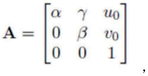 Wherein α ═ fD, β is f/dy; f is the focal length of the camera; dx represents the width of one pixel in the x-axis direction, and dy represents the width of one pixel in the y-axis direction; (u)0,ν0) The principal point, called the image plane, is also an intrinsic parameter of the camera; gamma represents the scale deviation of the pixel points in the x and y directions;
s3, according to the shot picture and the formula Extracting reliable depth information, wherein D represents the depth information, D represents the reliable depth information when being reliable, and D represents unreliable depth information when being nonreable; i represents the intensity value, T represents the threshold value T obtained by Otsu method;
s4, respectively fitting respective calibration plate plane coordinates to the Kinect camera and the TOF camera according to the reliable depth information;
s5, restoring the actual three-dimensional coordinate sets of the corner points of the Kinect camera and the TOF camera under the respectively fitted calibration plate plane coordinates by combining the internal parameters;
s6, solving a least square conversion matrix between the Kinect camera and the TOF camera according to the actual three-dimensional coordinate sets of the corner points of the Kinect camera and the TOF camera;
s7, performing coordinate conversion on the reliable depth information acquired by the Kinect camera and the TOF camera according to the least square conversion matrix to obtain depth fusion information;
s8, matching color information acquired by the Kinect camera with depth fusion information;
s9, performing point cloud registration on the matched image information based on the space distance between points to acquire three-dimensional information, specifically comprising the following steps:
s91: selecting a source control set from a source data set P, specifically:
randomly extracting four coplanar points s in the source data set P1,s2,s3,s4In which { s }1,s2,s3,s4Satisfy:


wherein, the overlapping ratio between the source data set P and the target data set Q is omega, and the average point cloud distance d of the source data set PavgMaximum point cloud distance dmaxAnd a distance threshold Δ davg*0.1;
Finding a straight line s1s3And s2s4Approximate intersection e ofsObtaining a coplanar five-point set Fs={s1,s2,s3,s4,es};
The coplanar five-point set is expressed by the following four characteristic values of the coplanar five-point set:
diagonal single ratio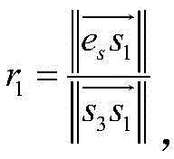 Diagonal single ratio
 ③ included angle between two adjacent sides
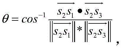 ④FsColor vector of color value corresponding to each point in RGB color space: cs={cs1,cs2,cs3,cs4,ces};
Coplanar five-point set FsAnd its corresponding color control set CsCo-composing a source control setS={Fs,Cs};
S92: in the target data set Q, selecting a color similarity control set according to the source control set;
s93: performing ICP (inductively coupled plasma) criterion on the source control set P and the color similarity control set to obtain an optimal transformation matrix, and splicing point clouds in the source data set P and the target data set Q by using the optimal transformation matrix to obtain three-dimensional information;
wherein the source data set P and the target data set Q are depth fusion information under different viewing angles.
2. The heterogeneous depth camera-based three-dimensional information acquisition method according to claim 1, wherein:
the step of S92 is specifically:
searching a coplanar five-point set F with all characteristic values satisfying equations (5) - (8) in a target data set Qt={t1,t2,t3,t4,et};

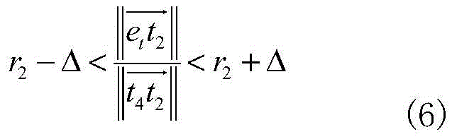

DC≤C (8)
Wherein Representing an angle error threshold between the coplanar five-point sets;
etaccording to coplanar quadrilaterals t1t2t3t4Recalculating the intersection point;
c is the measurement of the color difference between the source control set and the similar control set by the point cloud color distance threshold;
DCis CsAnd CtThe color difference therebetween;
each coplanar five-point set in the similar control set has a corresponding color vector set
All C satisfying the formula (8)tCoplanar five-point set F corresponding to the sametForming color similarity control set T ═ T1,T2,...,Tn}。
3. The heterogeneous depth camera-based three-dimensional information acquisition method according to claim 2, wherein:
the step of S93 is specifically:
controlling the color similarity to a set Ti={T1,i,T2,i,...,Tm,i,.. } and source control set Si={Fs,i,Cs,iSolving a rotation matrix R by using a least square methodm,iAnd a translation matrix tm,i(ii) a Wherein m represents one of the color similarity control sets; i represents the number of times;
is derived from the conversion relation p'm,i=Rm,i*p+tm,iTransforming a point P in the source data set P to the coordinate of the target set Q;
finding p 'in target set Q'm,iPoint of minimum distance, this point and p'm,iIs p'm,iEuclidean distance d (p ') from target point set Q'm,i,Q);
If d (p'm,iQ) is less than or equal to delta, then the point p is in the maximum consistent set, LCPm,iThe number of (2) is increased by 1;
LCPm,iwhen the number is maximum, the corresponding rotation matrix Rm,iAnd a translation matrix tm,iIs an optimal transformation matrix;
and splicing point clouds in the source data set P and the target data set Q according to the optimal transformation matrix to obtain three-dimensional information.
4. The heterogeneous depth camera-based three-dimensional information acquisition method according to claim 1, wherein:
the step of S4 is specifically:
three-dimensional coordinates (x) of corner pointsd,yd,zd)


zd=Dp
Wherein (x)o,yo) As the projection point of the optical center on the image, dx, dy is the pixel pitch of the Kinect camera 1, DpFitting a plane equation by using the three-dimensional coordinates of the angular points, wherein the depth value is corresponding to the Kinect camera 1, and the focal length is f;
assuming that the plane equation is aX + bY + cZ ═ d (9), the optimal equation coefficients a, b, c, and d can be obtained bY the least square method to fit the plane.
5. The heterogeneous depth camera-based three-dimensional information acquisition method according to claim 4, wherein:
the step of S5 is specifically:
suppose a certain point corner point H on the image coordinates, whose image coordinates are (x)h,yh),(xo,yo) Is the projection point of the optical center on the image, dx and dy are the pixel distances between the corner point H and the Kinect camera and the TOF camera, DhAnd f, the straight line equation of the line connecting the optical center and the point H is as follows:
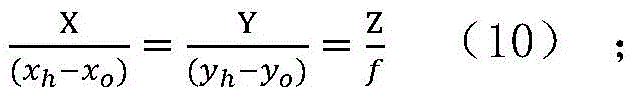
the intersection point of the linear equation and the plane equation is the actual three-dimensional coordinate of the corner point;
from the above equations (9) and (10), the actual three-dimensional coordinates of the corner points (x, y, z) are found as:


so far, the actual three-dimensional coordinate set H of all corner points is obtained1={h1,h2,…hnLike this, the actual three-dimensional coordinate set H of the corner point obtained by another camera2={h1,h2,…hn}。
6. The heterogeneous depth camera-based three-dimensional information acquisition method according to claim 1, wherein:
the step of S6 is specifically:
solving a least square conversion matrix (R) between the depth data set T of the TOF camera 2 and the depth data set K of the Kinect camera 1 by utilizing a SVD singular value solving method1,t1) Namely:

wherein H1、H2The actual three-dimensional coordinate sets of the corner points corresponding to the Kinect camera and the TOF camera respectively, and n is a positive integer and represents the number of the corner points.
Priority Applications (1)
| Application Number | Priority Date | Filing Date | Title |
|---|---|---|---|
| CN201611050176.3A CN106780618B (en) | 2016-11-24 | 2016-11-24 | Three-dimensional information acquisition method and device based on heterogeneous depth camera |
Applications Claiming Priority (1)
| Application Number | Priority Date | Filing Date | Title |
|---|---|---|---|
| CN201611050176.3A CN106780618B (en) | 2016-11-24 | 2016-11-24 | Three-dimensional information acquisition method and device based on heterogeneous depth camera |
Publications (2)
| Publication Number | Publication Date |
|---|---|
| CN106780618A CN106780618A (en) | 2017-05-31 |
| CN106780618B true CN106780618B (en) | 2020-11-03 |
Family
ID=58912883
Family Applications (1)
| Application Number | Title | Priority Date | Filing Date |
|---|---|---|---|
| CN201611050176.3A Expired - Fee Related CN106780618B (en) | 2016-11-24 | 2016-11-24 | Three-dimensional information acquisition method and device based on heterogeneous depth camera |
Country Status (1)
| Country | Link |
|---|---|
| CN (1) | CN106780618B (en) |
Families Citing this family (21)
| Publication number | Priority date | Publication date | Assignee | Title |
|---|---|---|---|---|
| CN107091643A (en) * | 2017-06-07 | 2017-08-25 | 旗瀚科技有限公司 | A kind of indoor navigation method based on many 3D structure lights camera splicings |
| CN107480612A (en) * | 2017-07-31 | 2017-12-15 | 广东欧珀移动通信有限公司 | Recognition methods, device and the terminal device of figure action |
| CN109729721B (en) | 2017-08-29 | 2021-04-16 | 深圳市汇顶科技股份有限公司 | Optical ranging method and optical ranging device |
| CN107507235B (en) * | 2017-08-31 | 2020-11-10 | 山东大学 | Registration method of color image and depth image acquired based on RGB-D equipment |
| CN108038453A (en) * | 2017-12-15 | 2018-05-15 | 罗派智能控制技术(上海)有限公司 | A kind of driver's state-detection and identifying system based on RGBD |
| CN108470323B (en) * | 2018-03-13 | 2020-07-31 | 京东方科技集团股份有限公司 | An image stitching method, computer equipment and display device |
| CN108845332B (en) * | 2018-07-04 | 2020-11-20 | 歌尔光学科技有限公司 | Depth information measurement method and device based on TOF module |
| CN109272555B (en) * | 2018-08-13 | 2021-07-06 | 长安大学 | A method of obtaining and calibrating external parameters of RGB-D camera |
| CN109377551B (en) * | 2018-10-16 | 2023-06-27 | 北京旷视科技有限公司 | Three-dimensional face reconstruction method and device and storage medium thereof |
| CN109767464B (en) * | 2019-01-11 | 2023-03-28 | 西南交通大学 | Point cloud registration method with low overlapping rate |
| CN109886905B (en) * | 2019-01-25 | 2023-06-16 | 江苏大学 | A Navigation Line Extraction and Recognition Method Based on Color Depth Fusion of Kinect Sensor |
| CN109949350B (en) * | 2019-03-11 | 2021-03-02 | 中国矿业大学(北京) | A Multitemporal Point Cloud Automatic Registration Method Based on Morphological Invariant Features |
| CN110110614A (en) * | 2019-04-19 | 2019-08-09 | 江苏理工学院 | A kind of gesture identifying device and method based on 3D camera |
| CN110189371B (en) * | 2019-05-20 | 2023-06-30 | 东南大学 | A mouse balance state discrimination device and method based on TOF depth camera |
| CN110930411B (en) * | 2019-11-20 | 2023-04-28 | 浙江光珀智能科技有限公司 | A method and system for human body segmentation based on depth camera |
| CN113096154B (en) * | 2020-01-08 | 2023-02-21 | 浙江光珀智能科技有限公司 | A target detection and tracking method and system based on obliquely mounted depth cameras |
| CN111654626B (en) * | 2020-06-05 | 2021-11-30 | 合肥泰禾智能科技集团股份有限公司 | High-resolution camera containing depth information |
| CN111681282A (en) * | 2020-06-18 | 2020-09-18 | 浙江大华技术股份有限公司 | A kind of pallet identification processing method and device |
| CN112734862A (en) * | 2021-02-10 | 2021-04-30 | 北京华捷艾米科技有限公司 | Depth image processing method and device, computer readable medium and equipment |
| CN113312992A (en) * | 2021-05-18 | 2021-08-27 | 中山方显科技有限公司 | Dynamic object sensing and predicting method based on multi-source sensor information fusion |
| CN117190911B (en) * | 2023-09-06 | 2024-06-25 | 中国铁建大桥工程局集团有限公司 | Linear monitoring method for steel truss arch bridge construction based on three-dimensional laser scanning |
Citations (3)
| Publication number | Priority date | Publication date | Assignee | Title |
|---|---|---|---|---|
| KR20120047482A (en) * | 2010-11-04 | 2012-05-14 | 삼성전자주식회사 | Calibration apparatus and method between heterogeneous cameras using plane area |
| CN103426200A (en) * | 2013-08-26 | 2013-12-04 | 天津大学 | Tree three-dimensional reconstruction method based on unmanned aerial vehicle aerial photo sequence image |
| CN106097348A (en) * | 2016-06-13 | 2016-11-09 | 大连理工大学 | A Fusion Method of 3D Laser Point Cloud and 2D Image |
Family Cites Families (3)
| Publication number | Priority date | Publication date | Assignee | Title |
|---|---|---|---|---|
| CN101582165B (en) * | 2009-06-29 | 2011-11-16 | 浙江大学 | Camera array calibration algorithm based on gray level image and spatial depth data |
| US9332243B2 (en) * | 2012-10-17 | 2016-05-03 | DotProduct LLC | Handheld portable optical scanner and method of using |
| US20150103200A1 (en) * | 2013-10-16 | 2015-04-16 | Broadcom Corporation | Heterogeneous mix of sensors and calibration thereof |
-
2016
- 2016-11-24 CN CN201611050176.3A patent/CN106780618B/en not_active Expired - Fee Related
Patent Citations (3)
| Publication number | Priority date | Publication date | Assignee | Title |
|---|---|---|---|---|
| KR20120047482A (en) * | 2010-11-04 | 2012-05-14 | 삼성전자주식회사 | Calibration apparatus and method between heterogeneous cameras using plane area |
| CN103426200A (en) * | 2013-08-26 | 2013-12-04 | 天津大学 | Tree three-dimensional reconstruction method based on unmanned aerial vehicle aerial photo sequence image |
| CN106097348A (en) * | 2016-06-13 | 2016-11-09 | 大连理工大学 | A Fusion Method of 3D Laser Point Cloud and 2D Image |
Also Published As
| Publication number | Publication date |
|---|---|
| CN106780618A (en) | 2017-05-31 |
Similar Documents
| Publication | Publication Date | Title |
|---|---|---|
| CN106780618B (en) | Three-dimensional information acquisition method and device based on heterogeneous depth camera | |
| Ishikawa et al. | Lidar and camera calibration using motions estimated by sensor fusion odometry | |
| CN112001926B (en) | RGBD multi-camera calibration method, system and application based on multi-dimensional semantic mapping | |
| Zhu et al. | Fusion of time-of-flight depth and stereo for high accuracy depth maps | |
| CN105184857B (en) | Monocular vision based on structure light ranging rebuilds mesoscale factor determination method | |
| CN102073874B (en) | Geometric constraint-attached spaceflight three-line-array charged coupled device (CCD) camera multi-image stereo matching method | |
| CN111210481A (en) | Depth estimation acceleration method of multiband stereo camera | |
| CN108629829B (en) | A three-dimensional modeling method and system combining dome camera and depth camera | |
| CN106485690A (en) | Cloud data based on a feature and the autoregistration fusion method of optical image | |
| CN102938142A (en) | Method for filling indoor light detection and ranging (LiDAR) missing data based on Kinect | |
| CN103106688A (en) | Indoor three-dimensional scene rebuilding method based on double-layer rectification method | |
| CN113554708A (en) | Complete calibration method of linear structured light vision sensor based on single cylindrical target | |
| CN107154014A (en) | A kind of real-time color and depth Panorama Mosaic method | |
| Khoshelham et al. | Generation and weighting of 3D point correspondences for improved registration of RGB-D data | |
| CN116309813A (en) | A Solid-state LiDAR-Camera Tightly Coupled Pose Estimation Method | |
| CN111415375B (en) | SLAM method based on multi-fisheye camera and double-pinhole projection model | |
| Bileschi | Fully automatic calibration of lidar and video streams from a vehicle | |
| CN118918265A (en) | Three-dimensional reconstruction method and system based on monocular camera and line laser | |
| Nguyen et al. | CalibBD: Extrinsic calibration of the LiDAR and camera using a bidirectional neural network | |
| CN118537216A (en) | Outdoor large scene panorama stitching method based on unmanned aerial vehicle inclined video | |
| CN116295351B (en) | A mapping method and system integrating semi-direct vision and radar odometry | |
| Jin et al. | A novel stitching method for high-precision low-overlap thermal infrared array sweeping images | |
| Somanath et al. | Stereo+ kinect for high resolution stereo correspondences | |
| Weinmann et al. | Fusing passive and active sensed images to gain infrared-textured 3D models | |
| Chen et al. | Low cost and efficient 3D indoor mapping using multiple consumer RGB-D cameras |
Legal Events
| Date | Code | Title | Description |
|---|---|---|---|
| PB01 | Publication | ||
| PB01 | Publication | ||
| SE01 | Entry into force of request for substantive examination | ||
| SE01 | Entry into force of request for substantive examination | ||
| GR01 | Patent grant | ||
| GR01 | Patent grant | ||
| CF01 | Termination of patent right due to non-payment of annual fee | ||
| CF01 | Termination of patent right due to non-payment of annual fee |
Granted publication date: 20201103 |