CN106737001B - Automatic processing method and equipment for sound sheet of musical box - Google Patents
Automatic processing method and equipment for sound sheet of musical box Download PDFInfo
- Publication number
- CN106737001B CN106737001B CN201611126405.5A CN201611126405A CN106737001B CN 106737001 B CN106737001 B CN 106737001B CN 201611126405 A CN201611126405 A CN 201611126405A CN 106737001 B CN106737001 B CN 106737001B
- Authority
- CN
- China
- Prior art keywords
- sound
- shifting
- piece
- grinding
- sheet
- Prior art date
- Legal status (The legal status is an assumption and is not a legal conclusion. Google has not performed a legal analysis and makes no representation as to the accuracy of the status listed.)
- Active
Links
- 238000003672 processing method Methods 0.000 title claims abstract description 9
- 230000007246 mechanism Effects 0.000 claims abstract description 152
- 238000000227 grinding Methods 0.000 claims abstract description 145
- 239000000463 material Substances 0.000 claims abstract description 18
- 238000000034 method Methods 0.000 claims abstract description 17
- 230000009467 reduction Effects 0.000 claims abstract description 6
- 238000013016 damping Methods 0.000 claims description 46
- 230000005284 excitation Effects 0.000 claims description 31
- 238000005259 measurement Methods 0.000 claims description 27
- 230000008569 process Effects 0.000 claims description 11
- 238000003860 storage Methods 0.000 claims description 5
- 230000009471 action Effects 0.000 claims description 3
- 238000003825 pressing Methods 0.000 claims description 3
- 206010063659 Aversion Diseases 0.000 description 9
- 238000006073 displacement reaction Methods 0.000 description 6
- 238000010586 diagram Methods 0.000 description 5
- 238000005868 electrolysis reaction Methods 0.000 description 4
- 238000009434 installation Methods 0.000 description 3
- 235000010585 Ammi visnaga Nutrition 0.000 description 2
- 244000153158 Ammi visnaga Species 0.000 description 2
- 230000005540 biological transmission Effects 0.000 description 2
- 230000007547 defect Effects 0.000 description 2
- 238000004064 recycling Methods 0.000 description 2
- 238000007599 discharging Methods 0.000 description 1
- 230000000694 effects Effects 0.000 description 1
- 239000003792 electrolyte Substances 0.000 description 1
- 238000001125 extrusion Methods 0.000 description 1
- 238000007689 inspection Methods 0.000 description 1
- 238000004519 manufacturing process Methods 0.000 description 1
Images


Classifications
-
- B—PERFORMING OPERATIONS; TRANSPORTING
- B24—GRINDING; POLISHING
- B24B—MACHINES, DEVICES, OR PROCESSES FOR GRINDING OR POLISHING; DRESSING OR CONDITIONING OF ABRADING SURFACES; FEEDING OF GRINDING, POLISHING, OR LAPPING AGENTS
- B24B19/00—Single-purpose machines or devices for particular grinding operations not covered by any other main group
-
- B—PERFORMING OPERATIONS; TRANSPORTING
- B07—SEPARATING SOLIDS FROM SOLIDS; SORTING
- B07C—POSTAL SORTING; SORTING INDIVIDUAL ARTICLES, OR BULK MATERIAL FIT TO BE SORTED PIECE-MEAL, e.g. BY PICKING
- B07C5/00—Sorting according to a characteristic or feature of the articles or material being sorted, e.g. by control effected by devices which detect or measure such characteristic or feature; Sorting by manually actuated devices, e.g. switches
- B07C5/34—Sorting according to other particular properties
-
- B—PERFORMING OPERATIONS; TRANSPORTING
- B07—SEPARATING SOLIDS FROM SOLIDS; SORTING
- B07C—POSTAL SORTING; SORTING INDIVIDUAL ARTICLES, OR BULK MATERIAL FIT TO BE SORTED PIECE-MEAL, e.g. BY PICKING
- B07C5/00—Sorting according to a characteristic or feature of the articles or material being sorted, e.g. by control effected by devices which detect or measure such characteristic or feature; Sorting by manually actuated devices, e.g. switches
- B07C5/36—Sorting apparatus characterised by the means used for distribution
- B07C5/361—Processing or control devices therefor, e.g. escort memory
- B07C5/362—Separating or distributor mechanisms
-
- B—PERFORMING OPERATIONS; TRANSPORTING
- B24—GRINDING; POLISHING
- B24B—MACHINES, DEVICES, OR PROCESSES FOR GRINDING OR POLISHING; DRESSING OR CONDITIONING OF ABRADING SURFACES; FEEDING OF GRINDING, POLISHING, OR LAPPING AGENTS
- B24B41/00—Component parts such as frames, beds, carriages, headstocks
- B24B41/002—Grinding heads
-
- B—PERFORMING OPERATIONS; TRANSPORTING
- B24—GRINDING; POLISHING
- B24B—MACHINES, DEVICES, OR PROCESSES FOR GRINDING OR POLISHING; DRESSING OR CONDITIONING OF ABRADING SURFACES; FEEDING OF GRINDING, POLISHING, OR LAPPING AGENTS
- B24B41/00—Component parts such as frames, beds, carriages, headstocks
- B24B41/02—Frames; Beds; Carriages
-
- B—PERFORMING OPERATIONS; TRANSPORTING
- B24—GRINDING; POLISHING
- B24B—MACHINES, DEVICES, OR PROCESSES FOR GRINDING OR POLISHING; DRESSING OR CONDITIONING OF ABRADING SURFACES; FEEDING OF GRINDING, POLISHING, OR LAPPING AGENTS
- B24B41/00—Component parts such as frames, beds, carriages, headstocks
- B24B41/06—Work supports, e.g. adjustable steadies
-
- B—PERFORMING OPERATIONS; TRANSPORTING
- B24—GRINDING; POLISHING
- B24B—MACHINES, DEVICES, OR PROCESSES FOR GRINDING OR POLISHING; DRESSING OR CONDITIONING OF ABRADING SURFACES; FEEDING OF GRINDING, POLISHING, OR LAPPING AGENTS
- B24B49/00—Measuring or gauging equipment for controlling the feed movement of the grinding tool or work; Arrangements of indicating or measuring equipment, e.g. for indicating the start of the grinding operation
- B24B49/003—Measuring or gauging equipment for controlling the feed movement of the grinding tool or work; Arrangements of indicating or measuring equipment, e.g. for indicating the start of the grinding operation involving acoustic means
-
- B—PERFORMING OPERATIONS; TRANSPORTING
- B24—GRINDING; POLISHING
- B24B—MACHINES, DEVICES, OR PROCESSES FOR GRINDING OR POLISHING; DRESSING OR CONDITIONING OF ABRADING SURFACES; FEEDING OF GRINDING, POLISHING, OR LAPPING AGENTS
- B24B49/00—Measuring or gauging equipment for controlling the feed movement of the grinding tool or work; Arrangements of indicating or measuring equipment, e.g. for indicating the start of the grinding operation
- B24B49/02—Measuring or gauging equipment for controlling the feed movement of the grinding tool or work; Arrangements of indicating or measuring equipment, e.g. for indicating the start of the grinding operation according to the instantaneous size and required size of the workpiece acted upon, the measuring or gauging being continuous or intermittent
-
- B—PERFORMING OPERATIONS; TRANSPORTING
- B24—GRINDING; POLISHING
- B24B—MACHINES, DEVICES, OR PROCESSES FOR GRINDING OR POLISHING; DRESSING OR CONDITIONING OF ABRADING SURFACES; FEEDING OF GRINDING, POLISHING, OR LAPPING AGENTS
- B24B51/00—Arrangements for automatic control of a series of individual steps in grinding a workpiece
-
- G—PHYSICS
- G01—MEASURING; TESTING
- G01H—MEASUREMENT OF MECHANICAL VIBRATIONS OR ULTRASONIC, SONIC OR INFRASONIC WAVES
- G01H17/00—Measuring mechanical vibrations or ultrasonic, sonic or infrasonic waves, not provided for in the preceding groups
Landscapes
- Engineering & Computer Science (AREA)
- Mechanical Engineering (AREA)
- Physics & Mathematics (AREA)
- Acoustics & Sound (AREA)
- General Physics & Mathematics (AREA)
- Grinding And Polishing Of Tertiary Curved Surfaces And Surfaces With Complex Shapes (AREA)
- Finish Polishing, Edge Sharpening, And Grinding By Specific Grinding Devices (AREA)
Abstract
The invention discloses an automatic processing method of a sound sheet of a musical box, which comprises the following steps: 1) the method comprises the steps of automatically measuring the frequency of each sound key of a sound piece material processed according to the shape requirement of the sound piece by a frequency measuring mechanism, 2) determining the required reduction amount of each sound key of the sound piece according to the difference value between the measured frequency and the required frequency of each sound key of the sound piece material, grinding the sound key by a grinding mechanism, determining the grinding starting position of each sound key of the sound piece by a sonar controller, 3) measuring the frequency after the required reduction amount of the sound key of the sound piece is ground, obtaining a qualified sound key if the frequency is qualified, and continuing to grind the sound key to be qualified or to obtain an unqualified sound key after the frequency is qualified, or continuing to grind the sound key to be qualified in the steps 2) and 3) for multiple times of circulation. It also correspondingly provides automatic processing equipment for the sound sheet of the musical box.
Description
Technical Field
The invention relates to a processing method and equipment of a sound sheet of a musical box.
Background
The sound sheet in the musical box refers to the sound producing component of the musical box, and is also called as a tuning fork, a sound board and the like. When manufacturing the sound sheet, in order to ensure that the sound sheet keys produce correct sound, each sound key on the sound sheet needs to be processed, and the sound wave frequency when the sound key vibrates needs to be adjusted. The conventional processing mode is manual operation: the worker holds the electric grinding head with one hand and the plectrum with the other hand, the tone key is shifted through the plectrum to judge the tone key frequency difference, then the electric grinding head is used for grinding, and the frequency measurement grinding is carried out again after the grinding until the key is qualified. Repeating the above process until all the keys of the sound sheet are qualified. The manual processing and grinding operation needs an operator with better operation skill, the labor intensity is high, and the potential safety hazard is large during the operation. The existing electrolysis method is used for carrying out frequency modulation on a music chip of a music box, the method is to place the music chip in electrolyte for electrolysis, and the quality of the music chip is changed by an electroerosion method, and the method also has some defects: the electrolysis head is fixed during electrolysis frequency modulation, only the sound piece root can be electrolyzed, and when the sound piece root is excessively electrolyzed, the sound piece head material cannot be electrolyzed to modulate frequency; in addition, real-time frequency modulation and frequency measurement cannot be realized.
Disclosure of Invention
The technical problem to be solved by the invention is to overcome the defects in the prior art and provide an automatic processing method of a musical box sound chip, so that the grinding amount of the sound chip can be accurately determined, and the qualified rate of the sound chip is improved.
The invention also correspondingly provides equipment for automatically processing the sound sheet of the eight-tone musical instrument, which can automatically produce the sound sheet.
The technical scheme adopted by the invention for solving the problems is as follows:
the automatic processing method of the sound sheet of the musical box comprises the following steps:
1) each sound key of the sound sheet material processed according to the shape requirement of the sound sheet is automatically subjected to frequency measurement by a frequency measurement mechanism,
2) determining the amount of reduction required for each key of the sound sheet according to the difference between the measured frequency and the required frequency of each key of the sound sheet material, grinding the keys by a grinding mechanism, determining the grinding starting position of each key of the sound sheet by a sonar sensor,
3) and (3) carrying out frequency measurement after the quantity required to be reduced for grinding the sound keys of the sound sheet is reduced, obtaining qualified sound keys if the frequency is qualified, and continuing to grind the sound keys in the steps 2) and 3) until the sound keys are qualified if the frequency is unqualified, or recycling the steps 2) and 3) for multiple times to finally obtain unqualified products.
The step 2) specifically includes: step 1, determining the grinding amount of a sound sheet; step 2, enabling the rotating grinding wheel to be close to the part of the sound piece to be ground; step 3, detecting and determining whether the grinding wheel is contacted with the sound piece by using a sonar sensor; and 4, finishing grinding the sound piece according to the determined grinding amount after the sound piece is contacted with the grinding wheel.
More specifically, the step 2) above includes: step 1, inputting the grinding amount of a sound sheet into a controller; step 2, a controller is adopted to control a grinding mechanism or a sound piece clamping mechanism, and a rotating grinding wheel is close to a part of the sound piece to be ground; step 3, detecting whether the sound chip is contacted with the grinding wheel by the sonar sensor; if the sound piece is not in contact with the grinding wheel, the grinding mechanism is continuously controlled to move the grinding wheel, or the sound piece clamping mechanism is controlled to move the sound piece until the sound piece is in contact with the grinding wheel; and 4, after the sound piece is contacted with the grinding wheel, the controller controls the grinding wheel to move through the grinding mechanism according to the set grinding amount, or the sound piece is moved through the sound piece clamping mechanism, and the grinding wheel grinds the sound piece in the moving process until the grinding amount set in the step 1 is finished.
Correspondingly, the automatic processing equipment for the sound sheet of the musical box comprises a clamping and transferring mechanism, a frequency measuring mechanism, a grinding mechanism and a controller; the clamping and transferring mechanism transfers the sound piece to the frequency measuring mechanism to detect the vibration frequency of the sound key, and sends a frequency signal to the controller, the controller determines the amount to be ground, the controller controls the clamping and transferring mechanism to transfer the sound piece to the grinding mechanism to grind the sound piece, the grinding mechanism is also provided with a sonar sensor, the sonar sensor detects and judges whether the sound key is contacted with the grinding mechanism, the sonar sensor sends a signal to the controller to start to measure the grinding amount after detecting that the sound key is contacted with the grinding mechanism, the sound piece is ground until the grinding amount determined by the control controller, and the controller controls the clamping and transferring mechanism to transfer the sound piece to the frequency measuring mechanism to detect the vibration frequency of the sound key, and whether the sound piece is qualified is judged.
Preferably, the grinding mechanism comprises a grinding wheel, a grinding wheel driver, a horizontal moving mechanism and a vertical moving mechanism, wherein the grinding wheel driver drives the grinding wheel to rotate, and the horizontal moving mechanism and the vertical moving mechanism respectively move the grinding wheel driver horizontally and vertically, so that the position of the grinding wheel can be conveniently moved and adjusted, and the moving distance of the grinding wheel can be accurately determined.
More specifically, the grinding wheel driver is a motor, the horizontal moving mechanism is a horizontal electric cylinder, the vertical moving mechanism is a vertical electric cylinder, the grinding wheel is fixed on a rotating shaft of the motor, the motor is fixed on a motor seat, the motor seat is fixed on a lifting rod of the vertical electric cylinder, the vertical electric cylinder is fixed on a moving plate of the horizontal electric cylinder, and the controller controls the rotation of the motor and the actions of the horizontal electric cylinder and the vertical electric cylinder.
Preferably, the grinding device further comprises an upper ejection mechanism, the upper ejection mechanism comprises an upper ejection block and an upper ejection block driving mechanism, the sound piece is located between the upper ejection block and the grinding wheel, the upper ejection block driving mechanism drives the upper ejection block to eject or leave the sound piece, and the controller controls the action of the upper ejection block driving mechanism.
More specifically, the upper ejector block driving mechanism is an upper ejector cylinder.
Preferably, the clamping and transferring mechanism comprises a carriage, a carriage driving part, a clamping pressure plate, a pressure plate driving part, an upright post, a sound piece seat, a blanking push plate and a push plate driving part; the pressing plate driving part, the upright post, the sound sheet seat and the push plate driving part are fixed on the carriage, and the carriage driving part drives the carriage to move horizontally; the middle section of clamping pressure plate and the upper end of vertical stand are through pivot swing joint, and clamping pressure plate's one end is driven by clamp plate driver part and is gone up and down, and clamping pressure plate's the other end has the pressure head, and clamping pressure plate one end lift drive pressure head and lift or push down, sets up the sound piece seat under the pressure head, and sound piece seat top sets up the unloading push pedal, and the unloading push pedal is located the side below of pressure head, and push pedal driver part drives the unloading push pedal and translates in sound piece seat top.
Preferably, the frequency measurement mechanism includes the driver, the excitation axle, the driver can drive the excitation axle rotatory, still include a plurality of plectrums, a plurality of damping fin are the tourus that the structure is the same, the body of plectrum is the tourus, this excircle of plectrum has outstanding group tooth, it has the breach to open on the plectrum body excircle of next-door neighbour group tooth, breach on every plectrum is all in the same one side of dialling the tooth, plectrum body external diameter is the same with the damping fin external diameter, plectrum and damping fin interval ground are installed in the excitation axle, the plectrum body, the damping fin, the excitation axle is coaxial, dial tooth on a plurality of plectrums after the installation, the breach staggers each other along the.
Preferably, each damping fin excircle and each plectrum body excircle all have an axial recess, and the axial recess forms the communicating logical groove of axial.
Preferably, the processing equipment further comprises a feeding structure, and the feeding structure comprises a storage bin, a shifting cylinder, a shifting push plate, a shifting guide rail, a feeding cylinder, a feeding push plate and a feeding guide rail; the left side and the right side of the lower part of the bin are provided with openings, the shifting push plate is driven by the shifting air cylinder to slide in the shifting guide rail, the push sheet on the shifting push plate extends into the opening on the left side of the bin to push out the sound sheet in the bin from the opening on the right side of the bin when sliding rightwards, the sound sheet is pushed into the feeding guide rail, and the feeding push plate is driven by the feeding air cylinder to push out the sound sheet in the feeding guide rail to the sound sheet seat of the clamping and transferring mechanism.
Preferably, a magnet is arranged in the side wall of the feeding guide rail, and the magnet is over against the right opening of the storage bin.
Preferably, the processing equipment further comprises a sorting mechanism, the sorting mechanism comprises a barrel, a rocker, a sorting cylinder and a swing plate, the upper end and the lower end of the barrel are open, the lower end of the barrel is divided into a left channel and a right channel, the sorting cylinder drives the rocker to be linked with the swing plate in the barrel, and the swing plate swings to open the left channel or the right channel; the clamping and transferring mechanism can send the sound sheet into the upper opening of the cylinder body.
Compared with the prior art, the invention has the advantages that: 1. the grinding mechanism is used for grinding the sound piece, and the sonar sensor is used for detecting and judging whether the grinding wheel is in contact with the sound piece, so that the reduction of the sound piece can be accurately controlled, and the qualified rate of the frequency of the processed sound piece is ensured. 2. The clamping transfer mechanism, the frequency measurement mechanism and the grinding mechanism are arranged, and the clamping transfer mechanism, the frequency measurement mechanism and the grinding mechanism are controlled by the controller, so that real-time frequency measurement and grinding of the sound piece can be realized, and the sound piece can be automatically and efficiently processed. 3. The feeding mechanism can realize automatic feeding, and the direction and the position of the sound piece conveyed each time are fixed, thereby providing convenience for the operation of subsequent procedures. 4. The grinding device can flexibly adjust the position of the grinding wheel, so that the head or the root of the tuning-lobe tuning key can be ground to increase or decrease the frequency of the tuning-lobe tuning key, and the requirement for preparing qualified tuning-lobe can be better met. 5. By adopting the frequency measurement mechanism, the plurality of plectrums and the damping sheets are arranged on the excitation shaft at intervals, the plectrums and the gaps on each plectrum are staggered, the plectrums on the plectrums can sequentially strike a plurality of sound keys when the excitation shaft rotates for a circle, and the excircle of the damping sheet and the excircle of the plectrum are contacted with the heads of the rest sound keys which are not struck, so that the vibration of the sound keys which are not struck is avoided, the noise interference on the sound keys which are being struck is prevented, and the frequency measurement precision of the sound keys which are struck is tested is improved. 6. The invention completes the whole process from feeding to discharging of qualified materials under the control of the control system, and has high automation degree.
Drawings
Fig. 1 is a schematic structural diagram of a musical piece of a musical box.
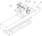
Fig. 2 is a schematic view of the overall structure of the embodiment of the present invention.
Fig. 3 is a schematic view of the structure of fig. 2 in another viewing direction.
Fig. 4 is a schematic structural diagram of a feeding mechanism according to an embodiment of the present invention.
Fig. 5 is a schematic view of the structure of fig. 4 in another viewing direction.
Fig. 6 is a partial top view of the structure of fig. 5.
Fig. 7 is a schematic structural diagram of a clamping and transferring mechanism according to an embodiment of the invention.
Fig. 8 is a schematic view of the structure of fig. 7 in another viewing direction.
Fig. 9 is a schematic structural diagram of a frequency measuring mechanism according to an embodiment of the present invention.
Fig. 10 is a partial structural view of fig. 9.
Fig. 11 is a schematic structural view of two of the paddles of fig. 10.
FIG. 12 is a schematic view of the damper and paddle of FIG. 10.
Fig. 13 is a partial structural schematic diagram of the frequency measuring mechanism in the use state.
Fig. 14 is a schematic structural view of a grinding mechanism according to an embodiment of the present invention.
Fig. 15 is a schematic structural view of the jack-up mechanism according to the embodiment of the present invention.
Fig. 16 is a schematic structural view of a sorting mechanism according to an embodiment of the present invention.
Fig. 17 is a schematic cross-sectional structure view in another direction of observation of fig. 16.
Detailed Description
The invention is further explained by the embodiment in the following with the attached drawings.
The structure of the sound sheet 7 is as shown in fig. 1, the head of the sound sheet 7 is uniformly distributed with a plurality of parallel sound keys 71, the heads of all the sound keys 71 are flush, and gaps are left between the sound keys 71.
The automatic processing method of the sound sheet of the musical box comprises the following steps:
1) each sound key of the sound sheet material processed according to the shape requirement of the sound sheet is automatically subjected to frequency measurement by a frequency measurement mechanism,
2) determining the amount of reduction required for each of the keys of the soundpiece according to the difference between the measured frequency and the required frequency of each of the keys of the soundpiece material, grinding the keys by a grinding mechanism, determining the starting position of grinding of each of the keys of the soundpiece by a sonar controller,
3) and (3) carrying out frequency measurement after the quantity required to be reduced for grinding the sound keys of the sound sheet is reduced, obtaining qualified sound keys if the frequency is qualified, and continuing to grind the sound keys in the steps 2) and 3) until the sound keys are qualified if the frequency is unqualified, or recycling the steps 2) and 3) for multiple times to finally obtain unqualified products.
The step 2) includes: step 1, inputting the grinding amount of a sound sheet into a controller; step 2, a controller is adopted to control a grinding mechanism or a sound piece clamping mechanism, and a rotating grinding wheel is close to a part of the sound piece to be ground; step 3, detecting whether the sound chip is contacted with the grinding wheel by the sonar sensor; if the sound piece is not in contact with the grinding wheel, the grinding mechanism is continuously controlled to move the grinding wheel, or the sound piece clamping mechanism is controlled to move the sound piece until the sound piece is in contact with the grinding wheel; and 4, after the sound piece is contacted with the grinding wheel, the controller controls the grinding wheel to move through the grinding mechanism according to the set grinding amount, or the sound piece is moved through the sound piece clamping mechanism, and the grinding wheel grinds the sound piece in the moving process until the grinding amount set in the step 1 is finished.
As shown in fig. 2 and 3, the automatic processing device for musical instrument sound sheets includes a feeding mechanism 1, a clamping and transferring mechanism 2, a frequency measuring mechanism 3, a grinding mechanism 4 (including an upper pushing mechanism 5), a sorting mechanism 6 (for convenience of observation, the sorting mechanism 6 is moved down properly in the figure), and a controller. The equipment is used for grinding the keys of the sound sheet of the music box, and the quality of the keys is changed through grinding so as to adjust the frequency of the keys during vibration.
The structure of the feeding mechanism 1 is as shown in fig. 4, 5 and 6, the feeding mechanism 1 comprises a displacement cylinder 11, a displacement push plate 12, a displacement guide rail 13, a bin 14, a feeding cylinder 17, a feeding push plate 16, a feeding guide rail 15 and a magnet 18, and all the components are arranged on a rack. The bin 14 is vertically arranged in a square cylinder shape, and the sound sheets 7 are stacked up and down inside the bin. The bottom left and right sides opening of feed bin 14, wherein left side opening and the switch-on of aversion guide rail 13, set up slidable aversion push pedal 12 in the guide rail 13, the right side bottom of aversion push pedal 12 has the push jack, the left side of aversion push pedal 12 is connected with the telescopic link of aversion cylinder 11, aversion push pedal 12 can be in aversion guide rail 13 horizontal slip under the drive of aversion cylinder 11, after the right slip, the push jack on aversion push pedal 12 right side can stretch into feed bin 14 from the left opening of feed bin 14, push the opening on feed bin 14 right side with sound piece 7 of lower floor, and further push sound piece 7 and get into in feeding guide rail 15. The rear part in the material loading guide rail 15 is provided with a slidable material loading push plate 16, the rear part of the material loading push plate 16 is connected with a telescopic rod of a material loading air cylinder 17, the material loading push plate 16 can slide back and forth in the material loading guide rail under the driving of the material loading air cylinder 17, and the sound piece 7 in the material loading guide rail 15 is pushed forward by sliding forward. And a magnet 18 is arranged in the side wall of the feeding guide rail 15, and the magnet 18 is opposite to the right opening of the storage bin 14.
Obviously, the size of the bin, the guide rail and the push plate is set according to the size of the sound sheet. The height of the left opening and the right opening at the bottom of the bin is larger than the thickness of the sound piece but smaller than the thickness of the two sound pieces, the width of the opening is slightly larger than the width of the sound piece, and the sizes of the push plate and the guide rail are set according to the size of the sound piece and the size of the bin, which belong to the common knowledge in the field and are not described again.
When loading is needed, the sound sheet 7 is filled in the bin 14, the sound sheets 7 are stacked up and down, and the sound keys 71 of the sound sheets 7 face to the right, namely the head of the sound sheet faces to the right. Then, the shifting cylinder 11 is started to drive the pushing piece of the shifting pushing plate 12 to push the bottom sound piece 7 into the feeding guide rail 15, and due to the magnetic force of the magnet 18, the head of the sound piece 7 is tightly attached to the right side edge of the guide rail, so that the sound piece 7 is positioned. And then the feeding cylinder 17 is started to drive the feeding push plate 16 to push the sound-extruding sheet 7 forwards so as to enable the sound-extruding sheet to move forwards, and the sound-extruding sheet enters the clamping and transferring mechanism.
The structure of the clamping and transferring mechanism 2 is shown in fig. 7 and 8, and the clamping and transferring mechanism comprises an electric cylinder 21, a carriage 25, a clamping pressure plate 23, a clamping cylinder 22, a blanking cylinder 24, a sound sheet seat 26, a blanking push plate 27 and an upright post 29.
The electric cylinder 21 serves as a driving member of the carriage 25, and drives the carriage 25 to translate. The carriage 25 is a carrying platform, and a clamping cylinder 22, a blanking cylinder 24, a sound sheet seat 26 and an upright post 29 are fixed on the carriage.
The clamping cylinder 22 is used as a driving component for driving one end of the clamping pressure plate 23 to ascend and descend, the bottom of the clamping cylinder 22 is fixed on the carriage 25, and the top end of the telescopic rod at the upper part is movably connected with one end of the clamping pressure plate 23.
The clamping pressure plate 23 is in a long strip shape, and one end of the clamping pressure plate is movably connected with the top end of a telescopic rod of the clamping cylinder 22: the end part of the clamping pressure plate 23 is provided with a vertical groove, the side edge of the vertical groove is provided with a transverse sliding groove 210, a connecting rod 211 is inserted into the transverse sliding groove, and the connecting rod 211 can slide back and forth in the transverse sliding groove 210; the telescopic rod 212 of the clamping cylinder is arranged up and down, and the upper end of the telescopic rod is connected with the connecting rod 211. The up-and-down movement of the telescopic rod 212 of the clamping cylinder can drive one end of the clamping pressure plate 23 to lift, the connecting rod 211 slides back and forth in the transverse sliding groove 210 in the lifting process, and the transverse sliding groove 210 is arranged to prevent the telescopic rod 21 of the clamping cylinder from shaking back and forth due to the fact that the end of the clamping pressure plate 23 has radian in the lifting process.
The other end of the clamping pressure plate 23 is provided with a pressure head, the middle section of the clamping pressure plate 23 is connected with the top end of a vertical upright post 29 through a rotating shaft, and the lower end of the upright post 29 is fixed on the carriage 25. The telescopic rod of the clamping cylinder 22 moves up and down to drive one end of the clamping pressure plate 23 to lift, the rotating shaft between the top end of the stand column 29 and the middle section of the clamping pressure plate is opposite to a supporting point, and one end of the clamping pressure plate 23 lifts to drive the pressure head at the other end to press down or tilt up.
The sound sheet seat 26 is fixed on the carriage 25, the upper plane of the sound sheet seat 26 is located under the pressure head of the clamping pressure plate, the upper plane of the sound sheet seat 26 is used as a platform for placing the sound sheet 7, in order to ensure that the positions for placing the sound sheet 7 are consistent, a limit strip 213 protruding out of the upper plane of the sound sheet seat is arranged on one side edge of the sound sheet seat 26, after the sound sheet 7 is placed each time, the side edge of the sound sheet 7 is tightly attached to the limit strip 213, namely the limit strip 213 is used as a reference for placing the side edge of the sound sheet 7.
In order to facilitate the disassembly and assembly and move the upright post 29 and the sound piece seat 26, the planker 25 is provided with a screw fixing bracket 214, the bracket 214 is provided with a mounting hole, the lower part of the upright post 29 can be inserted into the mounting hole, the lower end of the upright post 29 is fixed by the mounting hole, the lower part of the upright post 29 can also be provided with a shaft shoulder with the outer diameter larger than that of the mounting hole, and the mounting height of the upright post 29 is limited by the shaft shoulder. The sound stage 26 is also fixed to the bracket 214 to move the post 29 and the sound stage 26 simultaneously.
The blanking push plate 27 is flat, and the blanking push plate 27 is located above the voice coil holder 26 and below the side of the clamping platen press head, as shown in fig. 8.
The blanking cylinder 24 is used as a driving part of the blanking push plate 27, the blanking cylinder 24 is fixed on the upper plane of the carriage 25, the telescopic rod of the blanking cylinder 24 is horizontally arranged, the front end of the telescopic rod is fixedly connected with the blanking push plate 27, and the blanking cylinder 24 is started to drive the blanking push plate 27 to move forwards on the upper plane of the sound piece seat 26 to push the sound piece 7.
The working process of the clamping and transferring mechanism 2 is as follows: the shift electric cylinder 21 drives the electric cylinder carriage 25 to translate, so that the sound sheet seat 26 is close to the end face of the feeding guide rail 15 of the feeding mechanism 1, and the sound sheet 7 is pushed onto the sound sheet seat 26 by the feeding push plate 16. The clamping cylinder 22 is started to jack up one end of the clamping pressure plate 23, the pressure head at the other end of the clamping pressure plate 23 presses down the tail part of the clamping sound sheet 7, and the head part where the sound key 71 is located is suspended. The displacement electric cylinder 21 drives the displacement carriage 25 to translate to send the sound piece 7 to a processing station or a frequency measurement station of the grinding mechanism, after the processing or the frequency measurement is finished, the displacement carriage 25 moves to the position above the sorting mechanism 6, and the clamping cylinder 22 retracts into the telescopic rod 212 to enable the pressure head at the other end of the clamping cylinder 22 to lift up and loosen the sound piece 7. The blanking air cylinder 24 drives the blanking push plate 27 to pull the sound sheet 7 off the sound sheet seat 26 and enter the sorting mechanism.
The frequency measuring mechanism 3 is configured as shown in fig. 9 and 10, and includes a motor 31, a transmission belt 32, an excitation shaft 33, a frequency measuring sensor 34, a damping plate 35, and a paddle. The motor 31 can drive the exciting shaft 33 to rotate through the transmission belt 32, and the frequency measuring sensor 34 is used for detecting the frequency when the sound key 71 vibrates.
The body of the plectrum is a circular ring body, the excircle of the plectrum body is provided with protruding plectrum teeth, wherein the structure of the first plectrum 36 is shown in fig. 11, the first plectrum body of the plectrum body protrudes out of the first plectrum teeth 361, the excircle of the first plectrum body is provided with a first plectrum notch 362 and a first plectrum groove 363, and the radiuses of the notches and the bottom arcs of the grooves are smaller than the radius of the plectrum body. The first paddle recess 363 is on a counterclockwise side of the first paddle finger 361. The first plectrum notch 362 is close to the clockwise side of the first plectrum shifting tooth 361, namely the close proximity means that no arc of the excircle of the body exists between the notch and the shifting tooth, so that after the shifting tooth strikes a sound key, the sound key immediately enters the notch space after the plectrum rotates anticlockwise, and the sound key cannot be rubbed due to the existence of the arc of the excircle of the body.
The structure of the other shifting piece is similar to that of the first shifting piece 36, such as the second shifting piece 37 shown in fig. 11, and a second shifting piece notch 372 is formed on the clockwise side adjacent to the second shifting piece shifting tooth 371. The difference is that a second plectrum groove 373 with a larger radian is arranged on the anticlockwise side of the second plectrum. The other shifting pieces have similar structures with the first shifting piece 36 and the second shifting piece 37, except that the radian of the grooves on the shifting pieces and the positions of the opposite shifting teeth are different, and the grooves are communicated axially.
The radian of the second paddle recess 373 of the second paddle 37 may also be the same as that of the first paddle recess 363, but the recess 373 is connected to the second paddle tooth 371 by a segment of outer arc of the paddle body.
The vibration excitation effect can be realized if the radians of the grooves are the same.
Fig. 11 shows a schematic view of the first paddle 36 and the second paddle 37 after being attached to the exciting shaft 33 (the damper plate between the two paddles is omitted). The first shifting piece shifting tooth 361 and the first shifting piece notch 362 are mutually staggered with the second shifting piece shifting tooth 371 and the second shifting piece notch 372, are not in the same axial direction and are not overlapped in the circumferential direction, namely all the shifting teeth and notches are projected onto a cross section, and the first shifting tooth, the first notch, the second shifting tooth, the second notch, the third shifting tooth and the like are sequentially arranged. The first shifting piece groove 363 and the second shifting piece groove 373 are overlapped, i.e. are communicated in the axial direction. In a similar way, other shifting pieces are arranged behind the excitation shaft 33, the shifting teeth and the notches are staggered, and the grooves are axially communicated.
The damper 35 has a structure as shown in fig. 12, and the damper 35 includes a damper body 351 and a damper bar 352. The damping fin body 351 is a circular ring body, a section of arc-shaped damping strip 352 is fixed on the cylindrical surface of the damping fin body 351, and the width of the damping strip 352 is smaller than the thickness of the damping fin body 351, namely, a step is left on the cylindrical surface of the damping fin body 351. The diameter of the outer circle of the damping bar 352 is the same as the diameter of the plectrum body. The ends of the damping strips 352 are not in contact with each other, but rather leave a gap which, with respect to the entire damper 35, forms a damper groove 353. The structure of the first pick 36 and the damper 35 after installation is shown in fig. 12, and the first pick tooth 361 protrudes out of the damper bar 352 and the outer circle of the first pick body. The first paddle notch 362 is recessed relative to the damping bar 352 and the outer circle of the first paddle body. The first plectrum groove 363 is axially communicated with the damping fin groove 353, and after other plectrums and damping fins are arranged on the excitation shaft at intervals, all grooves are axially communicated to form a through groove, as shown in fig. 10. The width of the damping sheet and the width of the gap between the two damping sheets are designed according to the width of the sound key and the gap between the two sound keys, the width of the gap between the two damping strips after installation is larger than the width of one sound key 71, if the width of the gap is smaller than the width of the sound key 71, the sound key can cross the gap and contact with the excircle of the damping sheet, and when the plectrum teeth strike the sound key, the sound key cannot freely vibrate due to the friction of the damping sheets.
Preferably, 7 damping plates and 6 plectrums are arranged on the excitation shaft 33, the damping plates and the plectrums are arranged at intervals, and the plectrums and gaps of the plectrums are staggered by 45 degrees, as shown in fig. 11.
The working process of the mechanism is described by taking the example of exciting the vibration of the sound sheet with 18 sound keys by adopting the mechanism:
in an initial state, as shown in fig. 10, the through groove is located on one side of the excitation shaft, the clamping and transferring mechanism 2 moves all the keys 71 of the sound sheet 7 to be opposite to the through groove, the front ends of the heads of the keys 71 are located on contour lines of outer circles of the damping sheets and the plectrum, as the keys 71 are opposite to the grooves, and the grooves are sunken relative to the contour line of the outer circle of the plectrum, all the damping sheets and the plectrum do not contact with the keys at the moment, the 1 st sound key corresponds to the first plectrum 36 between the 1 st damping sheet and the 2 nd damping sheet, the 2 nd and 3 rd sound keys correspond to the 2 nd damping sheet, the 4 th sound key corresponds to the second plectrum 37 between the 2 nd damping sheet and the 3 rd damping sheet, the 5 th and 6 th sound keys are opposite to the 3 rd damping sheet, and so on the same order.
The starting motor 31 drives the excitation shaft 33 to rotate anticlockwise, the first plectrum 361 on the first plectrum 36 rotates by a certain angle to strike the 1 st sound key, and at the moment, other sound keys are contacted with the damping sheet 35 and the excircle of other plectrums, so that vibration cannot occur. After the striking, because the first pick notch 362 is arranged on the clockwise side close to the first pick tooth 361, the 1 st sound key will vibrate in the first pick notch 362, and the state at this time is as shown in fig. 13, and the frequency measurement sensor 34 detects the vibration frequency; the excitation shaft 33 rotates again, the excircle of the first plectrum 36 contacts the 1 st key, and the 1 st key stops vibrating; the excitation shaft 33 continues to rotate, the second plectrum 371 on the second plectrum 37 strikes the 4 th sound key, the struck 4 th sound key vibrates in the second plectrum notch 372, and the frequency measurement sensor 34 detects the frequency of the 4 th sound key; the excitation shaft 33 continues to rotate, the excircle of the second plectrum 37 contacts the 4 th key, and the 4 th key stops vibrating; the excitation shaft 33 continues to rotate, the third, fourth, fifth and sixth plectrums sequentially strike the 7 th, 10 th, 13 th and 16 th sound keys and sequentially measure the frequency, and the excitation shaft 33 rotates for a circle to complete the shifting and frequency measuring processes of the 6 sound keys. After rotating for a circle, the excitation shaft 33 returns to the initial position, then the whole sound piece 7 is driven by the clamping and transferring mechanism 2, so that the sound piece keys are displaced relative to the excitation shaft 33, the corresponding relation between the sound keys and the damping sheet and the plectrum is changed, and the 2 nd, 5 th, 37 th, 11 th, 14 th and 17 th sound keys are detected; the excitation shaft 33 rotates once to return to the initial position, and then the sound sheet is moved to detect the 3 rd, 6 th, 9 th, 12 th, 15 th and 18 th keys, so that the frequency measurement of all the keys is completed.
The grinding mechanism 4 is structured as shown in fig. 14, and the grinding mechanism 4 includes a vertical electric cylinder 41, a motor base 42, a grinding wheel 43, a motor 44, and a horizontal electric cylinder 45. The grinding wheel 43 is fixed on a rotating shaft of the motor 44, the motor 44 is fixed on a lifting rod of the vertical electric cylinder 41 through the motor seat 42, the vertical electric cylinder 41 is fixed on a moving plate of the horizontal electric cylinder 45, so that the grinding wheel 43 is driven by the motor 44 to rotate, and the position of the grinding wheel is adjusted through the vertical electric cylinder 41 and the horizontal electric cylinder 45 so as to control the position and the depth of a grinding sound key of the grinding wheel.
The grinding mechanism further comprises an upward pushing mechanism 5, the structure is shown in fig. 15, the upward pushing mechanism 5 comprises an upward pushing block 51, an upward pushing block fixing seat 52 and an upward pushing cylinder 54, the upward pushing block 51 is fixed on the upward pushing block fixing seat 52, the upward pushing block fixing seat 52 is fixed on a telescopic rod of the upward pushing cylinder 54, the upward pushing block 51 is located right below the grinding wheel 43, after the clamping and transferring mechanism 2 moves the sound piece 7 to the lower side of the grinding wheel 43, the upward pushing cylinder 54 drives the upward pushing block 51 to move upwards for pushing the sound piece 7, equivalently, the suspended part of the sound piece 7 is better supported, and the sound key of the sound piece is prevented from being deformed due to extrusion during grinding of the grinding wheel.
The sonar transducer 53 detects whether the rotating grinding wheel 43 contacts the sound chip, and the sonar transducer 53 may be fixed to the upper top block holder in the upper top mechanism, as shown in fig. 15, at a position close to the grinding wheel and the sound chip, so as to facilitate the inspection of the sound waves emitted by the sound chip.
Of course, the sonar transducer may be fixed to another part of the grinding mechanism as long as it can detect that the sound chip is in contact with the grinding wheel.
As shown in fig. 16 and 17, the sorting mechanism 6 includes a cylinder 61, a rocker 62, a sorting cylinder 63, and a swing plate 64. The sorting cylinder 63 is connected with a rocker 62, the rocker 62 is linked with a swing plate 64 in the cylinder 61, the upper end and the lower end of the cylinder are open, the lower end of the cylinder is divided into a left open channel and a right open channel, the right channel is opened when the swing plate 64 swings to the left side, and the left channel swings to the right side.
Obviously, the positions of the loading guide rail 15 of the loading mechanism 1, the sound piece seat 26 of the clamping and transferring mechanism, the frequency measuring station of the frequency measuring mechanism 3, the grinding station of the grinding mechanism 4 and the upper opening of the cylinder 61 of the sorting mechanism 6 are aligned to ensure that the clamping and transferring mechanism 2 can transfer the sound pieces among the mechanisms.
The working process of the automatic processing equipment comprises the steps of loading the sound piece 7 into a sound piece bin 14 of a loading mechanism 1 in an up-and-down superposition mode, controlling the loading mechanism 1 to push the sound piece into a sound piece seat 26 of a clamping and transferring mechanism 2 by a controller, clamping a tail part of the sound piece by a clamping pressure plate 23, driving a dragging plate 25 to translate by a shifting electric cylinder 21, moving a sound key of the sound piece to a through groove which is opposite to a vibration excitation shaft 33 of a frequency measurement mechanism 3, driving the vibration excitation shaft 33 to rotate by a controller starting motor 31, detecting the frequency of each sound key by a frequency measurement sensor 34 and transmitting the frequency to the controller, determining the quantity to be ground by the controller according to the frequency requirement of the qualified sound key, controlling the clamping and transferring mechanism 2 to send the sound piece 7 to the lower part of a grinding wheel 43 of a grinding mechanism 4 by the controller, starting the grinding wheel 43, adjusting the position of the grinding wheel 43 to be contacted with the sound key by a vertical electric cylinder 41 and a horizontal electric cylinder 45, the upper top block 51 tightly pushes up the sound keys of the sound chips, whether the grinding wheel 43 is in contact with the sound chips or not is detected through the sonar sensor 53, if the grinding wheel 43 is not in contact with the sound chips, the grinding wheel 43 is continuously close to the sound keys 71, the sonar sensor 53 sends signals to the controller after detecting that the grinding wheel 43 is in contact with the sound chips, and the controller starts to measure the grinding amount; after the sound piece is ground to a certain amount, the clamping and transferring mechanism 2 moves the sound piece to the frequency measuring mechanism 3 for frequency measurement again, whether the sound piece is qualified or not is judged, then the sound piece is moved to the upper part of the qualified cylinder 61 of the sorting mechanism 6 through the clamping and transferring mechanism 2, the sound piece 7 is loosened through the clamping and pressing plate 23, the blanking cylinder 24 is started to drive the blanking push plate 27 to push the sound piece 7 into the cylinder 61, the sorting cylinder 63 is started to drive the swinging plate 64 as required, and the left channel or the right channel below the cylinder 61 is opened to enable the sound piece to enter the corresponding qualified or unqualified product channel.
Claims (9)
1. The automatic processing method of the sound sheet of the musical box is characterized by comprising the following steps: the method comprises the following steps:
1) automatically measuring the frequency of each sound key of the sound sheet material processed according to the shape requirement of the sound sheet by a frequency measuring mechanism;
2) determining the required reduction amount of each sound key of the sound sheet according to the difference between the measured frequency and the required frequency of each sound key of the sound sheet material, grinding the sound keys by a grinding mechanism, and determining the grinding starting position of each sound key of the sound sheet by a sonar sensor;
3) carrying out frequency measurement after the quantity of the sound keys of the sound sheet required to be reduced is ground, obtaining qualified sound keys if the frequency is qualified, and continuing grinding in the step 2) and the step 3) until the sound keys are qualified or obtaining unqualified sound keys after the step 2) and the step 3) are repeatedly cycled;
the frequency measurement mechanism comprises a motor and an excitation shaft, the motor can drive the excitation shaft to rotate, the frequency measurement mechanism further comprises a plurality of shifting pieces and a plurality of damping pieces, the plurality of damping pieces are annular bodies with the same structure, a body of the shifting pieces is an annular body, protruding shifting teeth are arranged on the outer circle of the shifting piece body, gaps are formed in the outer circle of the shifting piece body close to the shifting teeth, the gaps on each shifting piece are located on the same side of the shifting teeth, the outer diameter of the shifting piece body is the same as that of the damping pieces, the shifting pieces and the damping pieces are installed on the excitation shaft at intervals, the shifting piece body, the damping pieces and the excitation shaft are coaxial, and the shifting teeth and the gaps on the plurality of shifting pieces are staggered with each other along.
2. The automatic processing method of musical instrument sound piece of claim 1, characterized in that: the step 2) comprises the following steps: step 1), inputting the grinding amount of the sound sheet into a controller; step 2), a controller is adopted to control a grinding mechanism or a voice chip clamping mechanism, and a rotating grinding wheel is close to a part of the voice chip to be ground; step 3), detecting whether the sound chip is contacted with the grinding wheel by the sonar sensor; if the sound piece is not in contact with the grinding wheel, the grinding mechanism is continuously controlled to move the grinding wheel, or the sound piece clamping mechanism is controlled to move the sound piece until the sound piece is in contact with the grinding wheel; and 4), after the sound piece is contacted with the grinding wheel, the controller controls the grinding wheel to move through the grinding mechanism according to the set grinding amount, or the sound piece is moved through the sound piece clamping mechanism, and the grinding wheel grinds the sound piece in the moving process until the grinding amount set in the step 1) is finished.
3. Musical instrument sound piece automatic processing equipment, its characterized in that: the device comprises a clamping and transferring mechanism, a frequency measuring mechanism, a grinding mechanism and a controller; the clamping and transferring mechanism transfers the sound piece to the frequency measuring mechanism to detect the vibration frequency of the sound key, and sends a frequency signal to the controller, the controller determines the amount to be ground, the controller controls the clamping and transferring mechanism to transfer the sound piece to the grinding mechanism to grind the sound piece, the grinding mechanism is also provided with a sonar sensor, the sonar sensor detects and judges whether the sound key is contacted with the grinding mechanism, the sonar sensor sends a signal to the controller to start to measure the grinding amount after detecting that the sound key is contacted with the grinding mechanism, the sound piece is ground until the grinding amount determined by the control controller, the controller controls the clamping and transferring mechanism to transfer the sound piece to the frequency measuring mechanism to detect the vibration frequency of the sound key, and whether the sound piece is qualified is judged; the frequency measurement mechanism comprises a motor and an excitation shaft, the motor can drive the excitation shaft to rotate, the frequency measurement mechanism further comprises a plurality of shifting pieces and a plurality of damping pieces, the plurality of damping pieces are annular bodies with the same structure, a body of the shifting pieces is an annular body, protruding shifting teeth are arranged on the outer circle of the shifting piece body, gaps are formed in the outer circle of the shifting piece body close to the shifting teeth, the gaps on each shifting piece are located on the same side of the shifting teeth, the outer diameter of the shifting piece body is the same as that of the damping pieces, the shifting pieces and the damping pieces are installed on the excitation shaft at intervals, the shifting piece body, the damping pieces and the excitation shaft are coaxial, and the shifting teeth and the gaps on the plurality of shifting pieces are staggered with each other along.
4. The automatic processing equipment of musical instrument sound piece of claim 3, characterized in that: the grinding mechanism comprises a grinding wheel, a grinding wheel driver, a horizontal moving mechanism and a vertical moving mechanism, the grinding wheel driver drives the grinding wheel to rotate, and the horizontal moving mechanism and the vertical moving mechanism respectively move the grinding wheel driver horizontally and vertically.
5. The automatic musical instrument tablet processing equipment according to claim 3 or 4, characterized in that: the clamping and transferring mechanism comprises a carriage, a carriage driving part, a clamping pressure plate, a pressure plate driving part, an upright post, a sound piece seat, a blanking push plate and a push plate driving part; the pressing plate driving part, the upright post, the sound sheet seat and the push plate driving part are fixed on the carriage, and the carriage driving part drives the carriage to move horizontally; the middle section of clamping pressure plate and the upper end of vertical stand are through pivot swing joint, and clamping pressure plate's one end is driven by clamp plate driver part and is gone up and down, and clamping pressure plate's the other end has the pressure head, and clamping pressure plate one end lift drive pressure head and lift or push down, sets up the sound piece seat under the pressure head, and sound piece seat top sets up the unloading push pedal, and the unloading push pedal is located the side below of pressure head, and push pedal driver part drives the unloading push pedal and translates in sound piece seat top.
6. The automatic processing equipment of musical instrument sound piece of claim 5, characterized in that: the grinding device further comprises an upper ejection mechanism, the upper ejection mechanism comprises an upper ejection block and an upper ejection block driving mechanism, the sound sheet is located between the upper ejection block and the grinding wheel, the upper ejection block driving mechanism drives the upper ejection block to eject or leave the sound sheet, and the controller controls the action of the upper ejection block driving mechanism.
7. The automatic musical instrument tablet processing equipment according to claim 3 or 4, characterized in that: the feeding mechanism comprises a storage bin, a shifting cylinder, a shifting push plate, a shifting guide rail, a feeding cylinder, a feeding push plate and a feeding guide rail; the left side and the right side of the lower part of the bin are provided with openings, the shifting push plate is driven by the shifting air cylinder to slide in the shifting guide rail, the push sheet on the shifting push plate extends into the opening on the left side of the bin to push out the sound sheet in the bin from the opening on the right side of the bin when sliding rightwards, the sound sheet is pushed into the feeding guide rail, and the feeding push plate is driven by the feeding air cylinder to push out the sound sheet in the feeding guide rail to the sound sheet seat of the clamping and transferring mechanism.
8. The automatic musical instrument tablet processing equipment according to claim 7, characterized in that: and a magnet is arranged in the side wall of the feeding guide rail and is over against the right opening of the storage bin.
9. The automatic musical instrument tablet processing equipment according to claim 3 or 4, characterized in that: the sorting mechanism comprises a barrel, a rocker, a sorting cylinder and a swing plate, wherein the upper end and the lower end of the barrel are open, the lower end of the barrel is divided into a left channel and a right channel, the sorting cylinder drives the rocker to be linked with the swing plate in the barrel, and the swing plate swings to open the left channel or the right channel; the clamping and transferring mechanism can send the sound sheet into the upper opening of the cylinder body.
Priority Applications (1)
| Application Number | Priority Date | Filing Date | Title |
|---|---|---|---|
| CN201611126405.5A CN106737001B (en) | 2016-12-09 | 2016-12-09 | Automatic processing method and equipment for sound sheet of musical box |
Applications Claiming Priority (1)
| Application Number | Priority Date | Filing Date | Title |
|---|---|---|---|
| CN201611126405.5A CN106737001B (en) | 2016-12-09 | 2016-12-09 | Automatic processing method and equipment for sound sheet of musical box |
Publications (2)
| Publication Number | Publication Date |
|---|---|
| CN106737001A CN106737001A (en) | 2017-05-31 |
| CN106737001B true CN106737001B (en) | 2020-03-24 |
Family
ID=58877524
Family Applications (1)
| Application Number | Title | Priority Date | Filing Date |
|---|---|---|---|
| CN201611126405.5A Active CN106737001B (en) | 2016-12-09 | 2016-12-09 | Automatic processing method and equipment for sound sheet of musical box |
Country Status (1)
| Country | Link |
|---|---|
| CN (1) | CN106737001B (en) |
Families Citing this family (3)
| Publication number | Priority date | Publication date | Assignee | Title |
|---|---|---|---|---|
| CN108686977A (en) * | 2018-03-27 | 2018-10-23 | 杭州星外星科技有限公司 | A kind of audio magnetic label detects screening installation automatically |
| CN109500583A (en) * | 2018-12-13 | 2019-03-22 | 日进教学器材(昆山)有限公司 | Oral cavity model automated attachment fitting machine |
| CN111986635A (en) * | 2020-07-30 | 2020-11-24 | 王正尧 | Method for modulating frequency of sound piece of music box and automatic rate modulation processing center |
Citations (8)
| Publication number | Priority date | Publication date | Assignee | Title |
|---|---|---|---|---|
| US6239336B1 (en) * | 1997-10-02 | 2001-05-29 | Sankyo Seiki Mfg. Co., Ltd. | Music box having an improved, rigid base frame |
| CN101324463A (en) * | 2008-06-23 | 2008-12-17 | 宁波韵升股份有限公司 | Vibration Isolation Device in Automatic Frequency Tuning of Sound Board |
| CN201224036Y (en) * | 2008-06-23 | 2009-04-22 | 宁波韵升股份有限公司 | Sound board locating and clamping device |
| CN100567914C (en) * | 2008-06-23 | 2009-12-09 | 宁波韵升股份有限公司 | Sensor and test device for testing octave keys |
| CN102737624A (en) * | 2012-06-19 | 2012-10-17 | 长沙理工大学 | Music sheet automatic frequency modulation equipment |
| CN202498426U (en) * | 2012-03-16 | 2012-10-24 | 王军波 | Sound sheet automatic cutting machine |
| CN204117582U (en) * | 2013-06-26 | 2015-01-21 | 宁波韵声机芯制造有限公司 | A kind of music box tablet frequency modulation device |
| CN206341481U (en) * | 2016-12-08 | 2017-07-18 | 深圳橙子自动化有限公司 | A kind of sorting mechanism for flexible circuitry board processing device |
Family Cites Families (1)
| Publication number | Priority date | Publication date | Assignee | Title |
|---|---|---|---|---|
| CN201342411Y (en) * | 2009-01-20 | 2009-11-11 | 广州市新豪精密五金制品有限公司 | Detection bench material distribution mechanism |
-
2016
- 2016-12-09 CN CN201611126405.5A patent/CN106737001B/en active Active
Patent Citations (8)
| Publication number | Priority date | Publication date | Assignee | Title |
|---|---|---|---|---|
| US6239336B1 (en) * | 1997-10-02 | 2001-05-29 | Sankyo Seiki Mfg. Co., Ltd. | Music box having an improved, rigid base frame |
| CN101324463A (en) * | 2008-06-23 | 2008-12-17 | 宁波韵升股份有限公司 | Vibration Isolation Device in Automatic Frequency Tuning of Sound Board |
| CN201224036Y (en) * | 2008-06-23 | 2009-04-22 | 宁波韵升股份有限公司 | Sound board locating and clamping device |
| CN100567914C (en) * | 2008-06-23 | 2009-12-09 | 宁波韵升股份有限公司 | Sensor and test device for testing octave keys |
| CN202498426U (en) * | 2012-03-16 | 2012-10-24 | 王军波 | Sound sheet automatic cutting machine |
| CN102737624A (en) * | 2012-06-19 | 2012-10-17 | 长沙理工大学 | Music sheet automatic frequency modulation equipment |
| CN204117582U (en) * | 2013-06-26 | 2015-01-21 | 宁波韵声机芯制造有限公司 | A kind of music box tablet frequency modulation device |
| CN206341481U (en) * | 2016-12-08 | 2017-07-18 | 深圳橙子自动化有限公司 | A kind of sorting mechanism for flexible circuitry board processing device |
Also Published As
| Publication number | Publication date |
|---|---|
| CN106737001A (en) | 2017-05-31 |
Similar Documents
| Publication | Publication Date | Title |
|---|---|---|
| CN106737001B (en) | Automatic processing method and equipment for sound sheet of musical box | |
| CN107470890A (en) | A kind of pump housing bent axle spring installs equipment online | |
| CN201503265U (en) | Straightness detection machine | |
| KR101411458B1 (en) | A shaft inspection apparatus | |
| CN106041770B (en) | Full automatic rotary type multistation grinding wheel molding machine | |
| CN119309485B (en) | Opening detection device and method with multi-opening powder metallurgy tray body | |
| CN115090541B (en) | Full-automatic department of walking detects machine | |
| CN118023172A (en) | Detection device and method for automatically detecting circuit on circuit board | |
| CN106002667B (en) | Grinding wheel molding machine conveying pushes material system | |
| CN103934216A (en) | Bearing vibrating noise sorting machine | |
| KR101760509B1 (en) | Centrifugal casting machine | |
| CN105665575B (en) | Process equipment for pickproof button | |
| KR101835104B1 (en) | A shaft inspection apparatus | |
| CN112895450B (en) | Leveling printing workbench for 3D printer | |
| JP4512548B2 (en) | Quality inspection equipment | |
| CN219996911U (en) | Tubular pile detection device | |
| CN116278130B (en) | Initiating explosive device powder forming system | |
| CN110369717A (en) | A kind of 3D printer of clout self-bring in type mould conformal cooling water channel | |
| CN109499920B (en) | Membrane box seat plate aging screening machine | |
| CN207534560U (en) | Music box tablet automatic processing device | |
| CN211542491U (en) | Feeding compaction assembly of mushroom seed packaging machine | |
| CN107900165B (en) | Round tube welding seam detection positioning mechanism | |
| KR101936876B1 (en) | Inspecting apparatus for motor casing fault | |
| CN220375715U (en) | Automatic feeding and discharging device for tapered roller bearing vibrating instrument | |
| CN210854218U (en) | Rotary discharging mechanism for outer ring of precision bearing |
Legal Events
| Date | Code | Title | Description |
|---|---|---|---|
| PB01 | Publication | ||
| PB01 | Publication | ||
| SE01 | Entry into force of request for substantive examination | ||
| SE01 | Entry into force of request for substantive examination | ||
| GR01 | Patent grant | ||
| GR01 | Patent grant |