CN106639930B - Vortex generator - Google Patents
Vortex generator Download PDFInfo
- Publication number
- CN106639930B CN106639930B CN201611195790.9A CN201611195790A CN106639930B CN 106639930 B CN106639930 B CN 106639930B CN 201611195790 A CN201611195790 A CN 201611195790A CN 106639930 B CN106639930 B CN 106639930B
- Authority
- CN
- China
- Prior art keywords
- hole
- turbine
- boss
- drill rod
- vortex generator
- Prior art date
- Legal status (The legal status is an assumption and is not a legal conclusion. Google has not performed a legal analysis and makes no representation as to the accuracy of the status listed.)
- Active
Links
Images


Classifications
-
- E—FIXED CONSTRUCTIONS
- E21—EARTH OR ROCK DRILLING; MINING
- E21B—EARTH OR ROCK DRILLING; OBTAINING OIL, GAS, WATER, SOLUBLE OR MELTABLE MATERIALS OR A SLURRY OF MINERALS FROM WELLS
- E21B21/00—Methods or apparatus for flushing boreholes, e.g. by use of exhaust air from motor
-
- Y—GENERAL TAGGING OF NEW TECHNOLOGICAL DEVELOPMENTS; GENERAL TAGGING OF CROSS-SECTIONAL TECHNOLOGIES SPANNING OVER SEVERAL SECTIONS OF THE IPC; TECHNICAL SUBJECTS COVERED BY FORMER USPC CROSS-REFERENCE ART COLLECTIONS [XRACs] AND DIGESTS
- Y02—TECHNOLOGIES OR APPLICATIONS FOR MITIGATION OR ADAPTATION AGAINST CLIMATE CHANGE
- Y02E—REDUCTION OF GREENHOUSE GAS [GHG] EMISSIONS, RELATED TO ENERGY GENERATION, TRANSMISSION OR DISTRIBUTION
- Y02E10/00—Energy generation through renewable energy sources
- Y02E10/20—Hydro energy
Landscapes
- Engineering & Computer Science (AREA)
- Life Sciences & Earth Sciences (AREA)
- Geology (AREA)
- Mining & Mineral Resources (AREA)
- Mechanical Engineering (AREA)
- Physics & Mathematics (AREA)
- Environmental & Geological Engineering (AREA)
- Fluid Mechanics (AREA)
- General Life Sciences & Earth Sciences (AREA)
- Geochemistry & Mineralogy (AREA)
- Earth Drilling (AREA)
Abstract
涡流发生器,属于钻井技术领域。上接头包括钻杆母扣、上圆柱体、上凸台,上圆柱体外表面均匀设有上螺旋条,上凸台端面轴向设有若干上过流孔,上过流孔与钻杆母扣内孔连通;接头包括下凸台、下圆柱体、钻杆公扣,下圆柱体外表面均匀设有若干下螺旋条,下凸台端面轴向设有若干下过流孔,该过流孔与钻杆公扣内孔连通;上、下接头通过中心轴连接,涡轮套于中心轴上,涡轮两端口分别套于上、下凸台上,涡轮外表面均匀设有若干扶正条;涡轮端面轴向设有若干通孔,该通孔上、下端分别与上、下过流孔相通。流体经上过流孔流经涡轮通孔,冲击涡轮,使扶正条旋转,从而刮削岩屑,而后从下过流孔流出。
A vortex generator belongs to the technical field of drilling. The upper joint includes a drill pipe box, an upper cylinder, and an upper boss. The outer surface of the upper cylinder is evenly provided with upper spiral strips. The inner hole is connected; the joint includes a lower boss, a lower cylinder, and a drill pipe pin. The outer surface of the lower cylinder is uniformly provided with a number of lower spiral strips, and the end surface of the lower boss is axially provided with a number of lower flow holes. The inner hole of the drill pipe pin is connected; the upper and lower joints are connected by the central shaft, the turbine is sleeved on the central shaft, and the two ports of the turbine are respectively sleeved on the upper and lower bosses, and the outer surface of the turbine is uniformly equipped with a number of centralizing strips; the end shaft of the turbine A number of through holes are arranged in the direction, and the upper and lower ends of the through holes communicate with the upper and lower flow holes respectively. The fluid flows through the turbine through hole through the upper flow hole, impacts the turbine, makes the centralizing bar rotate, thereby scraping the cuttings, and then flows out from the lower flow hole.
Description
技术领域technical field
本发明涉及一种涡流发生器,用于破坏岩屑床,属于钻井技术领域。The invention relates to a vortex generator used for destroying cuttings beds and belongs to the technical field of drilling.
背景技术Background technique
在直井钻井中,钻屑在环空下沉的方向和钻井液流动的方向平行相反,钻井液可以有效的把岩屑带到地面。但是在大斜度井段或水平井段钻井中,钻屑在重力的作用下垂直下沉,下沉的方向和钻井液流动的方向具有一定的角度甚至垂直,钻井液不能有效的把岩屑带到地面,沉积的岩屑在井底形成一个垫层(又称岩屑床),其产生的摩擦力阻碍了钻压的有效传递,严重时钻压加不上去,大大降低了钻进速度,甚至造成卡钻事故,并影响到固井质量。因此,如何清除井底岩屑床成为了钻井工程技术人员致力攻克的难题之一。In vertical well drilling, the sinking direction of cuttings in the annular space is parallel to and opposite to the direction of drilling fluid flow, and the drilling fluid can effectively bring cuttings to the surface. However, in the drilling of highly deviated or horizontal well sections, the cuttings sink vertically under the action of gravity, and the direction of sinking is at a certain angle or even perpendicular to the direction of drilling fluid flow, and the drilling fluid cannot effectively remove the cuttings. When brought to the ground, the deposited cuttings form a cushion (also known as the cuttings bed) at the bottom of the well, and the friction generated by it hinders the effective transmission of the drilling pressure. In severe cases, the drilling pressure cannot be increased, which greatly reduces the drilling speed. , and even cause pipe sticking accidents, and affect the quality of cementing. Therefore, how to remove the cuttings bed at the bottom of the well has become one of the difficult problems that drilling engineers and technicians strive to overcome.
目前,现场使用的岩屑床破坏器主要有辅助加压器附带轴向脉动破坏岩屑床、人字槽岩屑床破坏器、莲花瓣型岩屑床破坏器。第一种岩屑床破坏器优点是自身摩阻小,工作频率高,辅助加压和清除岩屑床兼顾,不足之处是轴向运动时光滑的外表面对清除岩屑床效果不明显,当中心轴达到最大行程时必须重新给钻头加压;第二和第三种在钻柱旋转时对清除岩屑床具有较为显著的效果,但是当滑动钻进时, 由于岩屑床破坏器较长,出于控制井身质量的需要,往往把岩屑床破坏器接在动力钻具上面,钻进时动力钻具以上的钻具是不转动的,因而上述的岩屑床破坏器也是不转动的,这样就失去了破坏岩屑床的作用,并产生额外的摩擦阻力阻碍钻压的有效传递。而打斜井段时经常采用滑动钻进,非常渴望有一种好的岩屑床破坏器,但到目前为止,上述问题仍未得到较好解决。At present, the cuttings bed breakers used on site mainly include auxiliary pressurizer with axial pulsation to break cuttings bed, herringbone groove cuttings bed breaker, and lotus petal cuttings bed breaker. The first kind of cuttings bed breaker has the advantages of small frictional resistance, high working frequency, and both auxiliary pressurization and cuttings bed removal. The disadvantage is that the smooth outer surface has no obvious effect on cuttings bed removal during axial movement. The bit must be repressurized when the central shaft reaches the maximum stroke; the second and third types have a more significant effect on clearing the cuttings bed when the drill string rotates, but when sliding drilling, because the cuttings bed breaker is more Long, because of the need to control the quality of the wellbore, the cuttings bed breaker is often connected to the power drilling tool, and the drilling tools above the power drilling tool do not rotate during drilling, so the cuttings bed breaker mentioned above is not suitable. In this way, the effect of destroying the cuttings bed will be lost, and additional frictional resistance will be generated to hinder the effective transmission of drilling pressure. However, sliding drilling is often used when drilling deviated well sections, and a good cuttings bed breaker is very much desired, but so far, the above-mentioned problems have not been well resolved.
发明内容Contents of the invention
本发明的目的是针对上述现有技术的不足,在分析了井下工况及各种井下工具的基础上,提供一种井下涡流发生器,用来破坏岩屑床。The object of the present invention is to provide a downhole vortex generator for destroying the cuttings bed on the basis of analyzing the downhole working conditions and various downhole tools in view of the above-mentioned deficiencies in the prior art.
本发明的目的是通过以下技术方案实现的:涡流发生器,其特征是,包括上接头、下接头以及涡轮,所述上接头包括上部的钻杆母扣、中部的上圆柱体、下部的上凸台,所述钻杆母扣与钻杆连接,并与之相通;所述上圆柱体外表面均匀设有若干左旋或右旋的上螺旋条;所述上凸台端面轴向设有若干上过流孔,上过流孔上端向上延伸并穿过上圆柱体,与钻杆母扣内孔连通;The object of the present invention is achieved through the following technical solutions: the vortex generator is characterized in that it includes an upper joint, a lower joint and a turbine, and the upper joint includes an upper drill pipe box, a middle upper cylinder, and a lower upper joint. Boss, the drill pipe box is connected with the drill pipe and communicated with it; the outer surface of the upper cylinder is uniformly provided with a number of left-handed or right-handed upper helical strips; the end surface of the upper boss is axially provided with a number of upper The flow hole, the upper end of the upper flow hole extends upward and passes through the upper cylinder, and communicates with the inner hole of the drill pipe box;
所述下接头包括上部的下凸台及芯轴、中部的下圆柱体、下部的钻杆公扣,所述钻杆公扣与钻杆连接,并与之相通;所述下圆柱体外表面均匀设有若干下螺旋条,下螺旋条与上螺旋条旋向相反;下凸台外径与上凸台外径相同,下凸台端面轴向设有若干下过流孔,该过流孔的下端向下延伸并穿过下圆柱体,与钻杆公扣内孔连通;The lower joint includes an upper lower boss and a mandrel, a lower cylinder in the middle, and a lower drill pipe male buckle, the drill pipe male buckle is connected with the drill pipe and communicates with it; the outer surface of the lower cylinder is uniform There are several lower spiral strips, the lower spiral strips are opposite to the upper spiral strips; the outer diameter of the lower boss is the same as that of the upper boss, and the end surface of the lower boss is axially provided with several lower flow holes, the flow holes The lower end extends downward and passes through the lower cylinder to communicate with the inner hole of the drill pipe pin;
所述上接头、下接头通过芯轴连接,所述涡轮中心设有通孔,并通过通孔套于芯轴上;所述涡轮两端口分别套于上、下凸台上,涡轮外表面均匀设有若干扶正条;所述涡轮端面轴向设有若干通孔,该通孔上、下端分别与上、下过流孔相通,流体经上过流孔流经涡轮通孔,冲击涡轮,使扶正条旋转,从而刮削岩屑,而后从下过流孔流出。The upper joint and the lower joint are connected by a mandrel, and the center of the turbine is provided with a through hole, and is sleeved on the mandrel through the through hole; the two ports of the turbine are respectively sleeved on the upper and lower bosses, and the outer surface of the turbine is uniform There are a number of righting bars; the end face of the turbine is provided with a number of through holes in the axial direction, the upper and lower ends of the through holes communicate with the upper and lower flow holes respectively, and the fluid flows through the through hole of the turbine through the upper flow holes and impacts the turbine, so that The centralizer bar rotates to scrape the cuttings, which then exit the lower orifice.
所述扶正条为竖直扶正条。The righting bar is a vertical righting bar.
所述扶正条中部开有T形孔,孔内安放T形伸缩块,T形孔与T形伸缩块间隙配合。There is a T-shaped hole in the middle part of the righting bar, and a T-shaped telescopic block is placed in the hole, and the T-shaped hole is matched with the T-shaped telescopic block.
所述T形孔由轴向孔、径向孔构成,所述T形伸缩块由轴向限位块、径向刮削块构成,轴向限位块置于轴向孔内,径向刮削块置于径向孔内,轴向孔的深度大于轴向限位块的厚度;The T-shaped hole is composed of an axial hole and a radial hole, and the T-shaped telescopic block is composed of an axial limiting block and a radial scraping block. The axial limiting block is placed in the axial hole, and the radial scraping block Placed in the radial hole, the depth of the axial hole is greater than the thickness of the axial limit block;
当扶正条处于涡轮下方时,对应的T形伸缩块在离心力和重力作用下,伸出T形孔外,即径向刮削块刮削井底的岩屑,当扶正条处于涡轮上方时,对应的T形伸缩块则缩回T形孔内。When the centralizing strip is below the turbine, the corresponding T-shaped telescopic block will protrude out of the T-shaped hole under the action of centrifugal force and gravity, that is, the radial scraping block scrapes the cuttings at the bottom of the well. When the centralizing strip is above the turbine, the corresponding The T-shaped telescopic block then retracts in the T-shaped hole.
所述涡轮两端与上、下凸台之间分别采用动配合密封。Dynamic fit seals are used between the two ends of the turbine and the upper and lower bosses respectively.
所述下凸台端面中心开有螺纹孔,用于和芯轴连接。A threaded hole is opened in the center of the end face of the lower boss for connecting with the mandrel.
所述上、下凸台外径分别小于上、下圆柱体的外径。The outer diameters of the upper and lower bosses are respectively smaller than the outer diameters of the upper and lower cylinders.
所述涡轮两端分别通过上轴承、下轴承与上、下凸台连接。The two ends of the turbine are respectively connected with the upper and lower bosses through the upper bearing and the lower bearing.
所述上过流孔为斜直孔,所述下过流孔为直孔。The upper flow hole is an oblique straight hole, and the lower flow hole is a straight hole.
在滑动钻进过程中,钻井液通过上接头的上过流孔(斜直孔),冲击涡轮叶片,带动涡轮旋转,涡轮下方靠近井底的T形槽(孔)内的(T形)伸缩块在离心力和自重的作用下就伸出来,刮削井底的岩屑,而处于涡轮上方的伸缩块则缩回T形槽(孔)内,避免因接触井壁而产生摩擦力。During the sliding drilling process, the drilling fluid passes through the upper flow hole (inclined straight hole) of the upper joint, impacts the turbine blades, drives the turbine to rotate, and the (T-shaped) in the T-shaped groove (hole) below the turbine near the bottom of the well expands and contracts. The block stretches out under the action of centrifugal force and self-weight to scrape the cuttings at the bottom of the well, while the telescopic block above the turbine retracts into the T-shaped slot (hole) to avoid friction due to contact with the well wall.
若是旋转钻进,上、下接头的螺旋条及涡轮的螺旋条(扶正条)都会从井底刮削岩屑,同时上返的液体进入下接头的螺旋槽(即下螺旋条之间的缝隙),经涡轮的螺旋槽(即扶正条之间的缝隙)后又从上接头反方向的螺旋槽(即上螺旋条之间的缝隙)流出,从而在涡流发生器的中间形成涡流,加剧了岩屑床的破坏。If it is rotary drilling, the helical strips of the upper and lower joints and the helical strips (righting strips) of the turbine will scrape cuttings from the bottom of the well, and at the same time, the liquid returned from the upper part will enter the helical groove of the lower joint (that is, the gap between the lower helical strips) After passing through the spiral groove of the turbine (that is, the gap between the centralizing strips), it flows out from the spiral groove in the opposite direction of the upper joint (that is, the gap between the upper spiral strips), thereby forming a vortex in the middle of the vortex generator, which intensifies the rock Destruction of the crumb bed.
由于涡流发生器较短(结构简单、不占空间),对测量井斜方位影响不大,故其可接在动力钻具以下,以取得更好的清除岩屑床效果。又由于钻井液流经涡流发生器时压力损耗不大,所以可在钻柱中间分段接入,效果更好。Since the vortex generator is relatively short (simple structure, does not take up space), it has little effect on measuring the inclination and azimuth of the well, so it can be connected below the power drilling tool to achieve a better effect of clearing the cuttings bed. And because the pressure loss is not large when the drilling fluid flows through the vortex generator, it can be connected in sections in the middle of the drill string, and the effect is better.
综上所述,无论是旋转钻进还是滑动钻进,涡流发生器都能较好的清除岩屑床。To sum up, the vortex generator can remove the cuttings bed well whether it is rotary drilling or sliding drilling.
附图说明Description of drawings
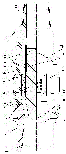
图1为本发明的结构示意图;Fig. 1 is a structural representation of the present invention;
图2为本发明中扶正条及T形孔的结构示意图;Fig. 2 is the structural representation of righting bar and T-shaped hole among the present invention;
图3为本发明中T形伸缩块的结构示意图;Fig. 3 is the structural representation of T-shaped telescopic block among the present invention;
图中:1上接头、2下接头、3涡轮、4钻杆母扣、5上圆柱体、6上凸台、7上螺旋条、8上过流孔、9下凸台、10下圆柱体、11钻杆公扣、12下螺旋条、13下过流孔、14芯轴、15扶正条、16通孔、17 T形孔、18 T形伸缩块、19轴向孔、20径向孔、21轴向限位块、22径向刮削块、23上轴承、24下轴承。In the figure: 1 upper joint, 2 lower joint, 3 turbine, 4 drill pipe box, 5 upper cylinder, 6 upper boss, 7 upper spiral bar, 8 upper flow hole, 9 lower boss, 10 lower cylinder , 11 drill pipe male button, 12 lower spiral bar, 13 lower flow hole, 14 mandrel, 15 centralizing bar, 16 through hole, 17 T-shaped hole, 18 T-shaped telescopic block, 19 axial hole, 20 radial hole , 21 axial limit block, 22 radial scraping block, 23 upper bearing, 24 lower bearing.
具体实施方式Detailed ways
如图1所示,涡流发生器由三个部件组成,上接头1、下接头2和涡轮3。上接头的上端为钻杆母扣4,其中间(上圆柱体5)外表面有若干左旋或右旋的上螺旋条7,其下面是外径略小于螺旋条根部外径的上凸台6(即上凸台外径小于上圆柱体外径)。As shown in Figure 1, the vortex generator consists of three parts, the upper joint 1, the lower joint 2 and the
上凸台的中间是一根芯轴(中心轴14),上端的母扣与钻杆相连接,母扣下面有若干上过流孔8(斜直孔)通到下面的台阶面,经过的流体可以冲击涡轮叶片(扶正条15)。In the middle of the upper boss is a mandrel (central shaft 14), and the upper end of the box is connected with the drill pipe. There are a number of upper flow holes 8 (slanted straight holes) below the box to the lower step surface. The fluid can impinge on the turbine blades (righting bars 15).
下接头的上部是下凸台9,该凸台外径与上凸台6的外径相同,下凸台端面开有若干下过流孔13(直孔),下过流孔上与涡轮的通孔16连通,下与钻杆公扣的内孔连通。下凸台的中间开有螺纹孔,用于和中心轴连接。The upper part of the lower joint is the
下接头中部的下圆柱体10,其外表面带有与上接头旋向相反的下螺旋条12,最下部是钻杆公扣,用来与钻杆连接。The
涡轮的中心带有通孔,套在芯轴(中心轴)上,外表面有若干竖直的扶正条15,扶正条的中间开有T形孔17,孔内安放T形伸缩块18,涡轮两端的孔分别套在上接头下端和下接头上端的凸台上,采用动配合密封。There is a through hole in the center of the turbine, which is sleeved on the mandrel (central shaft), and there are several
T形孔由轴向孔19、径向孔20构成,T形伸缩块由轴向限位块21、径向刮削块22构成,轴向限位块置于轴向孔内,径向刮削块置于径向孔内,轴向孔的深度大于轴向限位块的厚度。The T-shaped hole is composed of an
流体经上过流孔流经涡轮通孔,冲击涡轮,使扶正条旋转,从而刮削岩屑,而后从下过流孔流出(斜直孔出来的水流会为涡轮旋转提供一个冲击力,水流流经涡轮通孔,从直孔流出,直孔可以减小水流阻力)。当扶正条处于涡轮下方时,对应的T形伸缩块在离心力和重力作用下,伸出T形孔外,即径向刮削块刮削井底的岩屑,当扶正条处于涡轮上方时,对应的T形伸缩块则缩回T形孔内。The fluid flows through the through hole of the turbine through the upper flow hole, impacts the turbine, makes the centralizing bar rotate, thereby scraping the rock debris, and then flows out from the lower flow hole (the water flow out of the oblique straight hole will provide an impact force for the rotation of the turbine, and the water flow will Through the turbine through hole, it flows out from the straight hole, which can reduce the water flow resistance). When the centralizing strip is below the turbine, the corresponding T-shaped telescopic block will protrude out of the T-shaped hole under the action of centrifugal force and gravity, that is, the radial scraping block scrapes the cuttings at the bottom of the well. When the centralizing strip is above the turbine, the corresponding The T-shaped telescopic block then retracts in the T-shaped hole.
本发明中,上、下接头中间留有钻井液流通的腔道,因此,本发明在不影响钻井工作的基础上,采用上、下螺旋条、扶正条及伸缩块的组合方式,可更好的破坏岩屑床,使用效果更佳。In the present invention, there is a cavity for drilling fluid circulation between the upper and lower joints. Therefore, the present invention adopts the combination of upper and lower spiral strips, centralizing strips and telescopic blocks on the basis of not affecting the drilling work, which can be better. The destruction of the cuttings bed, the use of the effect is better.
Claims (7)
Priority Applications (1)
| Application Number | Priority Date | Filing Date | Title |
|---|---|---|---|
| CN201611195790.9A CN106639930B (en) | 2016-12-22 | 2016-12-22 | Vortex generator |
Applications Claiming Priority (1)
| Application Number | Priority Date | Filing Date | Title |
|---|---|---|---|
| CN201611195790.9A CN106639930B (en) | 2016-12-22 | 2016-12-22 | Vortex generator |
Publications (2)
| Publication Number | Publication Date |
|---|---|
| CN106639930A CN106639930A (en) | 2017-05-10 |
| CN106639930B true CN106639930B (en) | 2022-11-15 |
Family
ID=58834593
Family Applications (1)
| Application Number | Title | Priority Date | Filing Date |
|---|---|---|---|
| CN201611195790.9A Active CN106639930B (en) | 2016-12-22 | 2016-12-22 | Vortex generator |
Country Status (1)
| Country | Link |
|---|---|
| CN (1) | CN106639930B (en) |
Families Citing this family (2)
| Publication number | Priority date | Publication date | Assignee | Title |
|---|---|---|---|---|
| CN110469278A (en) * | 2019-08-09 | 2019-11-19 | 中国石油天然气股份有限公司 | A cuttings bed cleaning tool and method of use |
| CN115726738B (en) * | 2021-08-25 | 2024-04-30 | 中国石油天然气集团有限公司 | Self-rotating borehole cleaning tool for sliding drilling |
Citations (10)
| Publication number | Priority date | Publication date | Assignee | Title |
|---|---|---|---|---|
| US5651420A (en) * | 1995-03-17 | 1997-07-29 | Baker Hughes, Inc. | Drilling apparatus with dynamic cuttings removal and cleaning |
| CN201738848U (en) * | 2010-06-02 | 2011-02-09 | 西南石油大学 | Wellbore cleaning tool used in well drilling |
| CN102913155A (en) * | 2012-10-29 | 2013-02-06 | 陕西联盟物流有限公司 | Cuttings bed scavenger |
| CN102913157A (en) * | 2012-11-08 | 2013-02-06 | 中国石油天然气集团公司 | Underground sleeve rotational flow guider |
| CN203430446U (en) * | 2013-08-02 | 2014-02-12 | 天津市万众科技发展有限公司 | Horizontal well turbine sand cleaning device |
| CN103775009A (en) * | 2012-10-18 | 2014-05-07 | 中国石油化工股份有限公司 | Drilling power rock debris bed eraser |
| CN104265212A (en) * | 2014-07-28 | 2015-01-07 | 东北石油大学 | Borehole cleaning tool for drilling highly-deviated well |
| CN104675346A (en) * | 2015-02-15 | 2015-06-03 | 东北石油大学 | Split blade hydraulic-magnetic transmission well hole cleaning tool |
| CN105201430A (en) * | 2015-10-26 | 2015-12-30 | 东北石油大学 | Turbine drive cuttings bed cleaning device |
| CN206503576U (en) * | 2016-12-22 | 2017-09-19 | 扬州大泽石油工程技术有限公司 | Vortex generator |
Family Cites Families (3)
| Publication number | Priority date | Publication date | Assignee | Title |
|---|---|---|---|---|
| GB0513645D0 (en) * | 2005-07-02 | 2005-08-10 | Specialised Petroleum Serv Ltd | Wellbore cleaning method and apparatus |
| US8807217B2 (en) * | 2009-12-16 | 2014-08-19 | Bruce A. Tunget | Methods for using or removing unused rock debris from a passageway through subterranean strata using rock breaking apparatus |
| CN106246114A (en) * | 2016-10-24 | 2016-12-21 | 中国石油大学(北京) | Mill drill pipe nipple in horizontal well pulse |
-
2016
- 2016-12-22 CN CN201611195790.9A patent/CN106639930B/en active Active
Patent Citations (10)
| Publication number | Priority date | Publication date | Assignee | Title |
|---|---|---|---|---|
| US5651420A (en) * | 1995-03-17 | 1997-07-29 | Baker Hughes, Inc. | Drilling apparatus with dynamic cuttings removal and cleaning |
| CN201738848U (en) * | 2010-06-02 | 2011-02-09 | 西南石油大学 | Wellbore cleaning tool used in well drilling |
| CN103775009A (en) * | 2012-10-18 | 2014-05-07 | 中国石油化工股份有限公司 | Drilling power rock debris bed eraser |
| CN102913155A (en) * | 2012-10-29 | 2013-02-06 | 陕西联盟物流有限公司 | Cuttings bed scavenger |
| CN102913157A (en) * | 2012-11-08 | 2013-02-06 | 中国石油天然气集团公司 | Underground sleeve rotational flow guider |
| CN203430446U (en) * | 2013-08-02 | 2014-02-12 | 天津市万众科技发展有限公司 | Horizontal well turbine sand cleaning device |
| CN104265212A (en) * | 2014-07-28 | 2015-01-07 | 东北石油大学 | Borehole cleaning tool for drilling highly-deviated well |
| CN104675346A (en) * | 2015-02-15 | 2015-06-03 | 东北石油大学 | Split blade hydraulic-magnetic transmission well hole cleaning tool |
| CN105201430A (en) * | 2015-10-26 | 2015-12-30 | 东北石油大学 | Turbine drive cuttings bed cleaning device |
| CN206503576U (en) * | 2016-12-22 | 2017-09-19 | 扬州大泽石油工程技术有限公司 | Vortex generator |
Non-Patent Citations (2)
| Title |
|---|
| 大位移钻井岩屑床影响因素分析及清除技术探究;陈安明等;《电子测试》;20131101(第19期);第174-176页 * |
| 高效岩屑床清除钻杆作用机理;陈锋等;《石油学报》;20120315;第33卷(第2期);第298-303页 * |
Also Published As
| Publication number | Publication date |
|---|---|
| CN106639930A (en) | 2017-05-10 |
Similar Documents
| Publication | Publication Date | Title |
|---|---|---|
| CN105863514B (en) | A kind of hydraulically-controlled type reaming while drilling tool | |
| CN207960507U (en) | A kind of PDC milling bits | |
| CN207122301U (en) | A kind of drilling well sand cleaning tool | |
| CN110886582A (en) | Integrated drilling tool for crushing and cleaning drilling well debris deposit bed | |
| CN204113225U (en) | Spring casing well scraper | |
| CN106639930B (en) | Vortex generator | |
| CN105735928B (en) | Screw shaft formula local reverse-circulation core bit | |
| CN104763367B (en) | Well scraper integrated tool | |
| CN105422006A (en) | Adjustable underground rock breaking tool combining drilling and expanding | |
| US4312415A (en) | Reverse circulating tool | |
| CN115596355A (en) | Borehole repair tool and repair method while drilling in formation prone to diameter shrinkage | |
| CN112761558B (en) | Annular space acceleration rate swirler for vertical shaft | |
| CN110700762A (en) | Bit mud bag flushing aid while drilling | |
| CN220059488U (en) | Geological coring drilling tool capable of realizing continuous drilling with casing | |
| CN202882806U (en) | Drill column type debris bed eliminating tool | |
| CN109306853B (en) | Fishing device with bridging plug milling function | |
| CN203430446U (en) | Horizontal well turbine sand cleaning device | |
| CN218816239U (en) | Drilling tool integrating drilling and cutting | |
| CN204476270U (en) | A kind of reamer and reaming assembly of pulling back | |
| CN206111114U (en) | Horizontal well collection bits ware | |
| CN204754873U (en) | Belt cleaning device is scraped to sleeve pipe | |
| CN209780758U (en) | Hard rock reaming and repairing device for ground directional horizontal drilling | |
| RU2630497C2 (en) | Device for cleaning directional and horizontal wellbores from slime | |
| CN203867505U (en) | Milling shoe for borehole operation | |
| CN212154655U (en) | A kind of micro-reaming sand cleaning tool for drilling |
Legal Events
| Date | Code | Title | Description |
|---|---|---|---|
| PB01 | Publication | ||
| PB01 | Publication | ||
| SE01 | Entry into force of request for substantive examination | ||
| SE01 | Entry into force of request for substantive examination | ||
| TA01 | Transfer of patent application right |
Effective date of registration: 20221021 Address after: 102200 Beijing city Changping District Road No. 18 Applicant after: China University of Petroleum (Beijing) Address before: 225000 B507, A1 Floor, Yangzhou Science Park, Xi'an Jiaotong University, Wuzhou East Road, Yangzhou Development Zone, Jiangsu Province Applicant before: Yangzhou Daze Petroleum Engineering Technology Co.,Ltd. |
|
| TA01 | Transfer of patent application right | ||
| GR01 | Patent grant | ||
| GR01 | Patent grant |