CN106618405B - Glass cleaner with dual power supplies and control method thereof - Google Patents
Glass cleaner with dual power supplies and control method thereof Download PDFInfo
- Publication number
- CN106618405B CN106618405B CN201611170776.3A CN201611170776A CN106618405B CN 106618405 B CN106618405 B CN 106618405B CN 201611170776 A CN201611170776 A CN 201611170776A CN 106618405 B CN106618405 B CN 106618405B
- Authority
- CN
- China
- Prior art keywords
- power supply
- main
- detection circuit
- main power
- dual
- Prior art date
- Legal status (The legal status is an assumption and is not a legal conclusion. Google has not performed a legal analysis and makes no representation as to the accuracy of the status listed.)
- Active
Links
- 239000011521 glass Substances 0.000 title claims abstract description 46
- 230000009977 dual effect Effects 0.000 title claims abstract description 45
- 238000000034 method Methods 0.000 title claims abstract description 26
- 238000001514 detection method Methods 0.000 claims abstract description 69
- 238000004140 cleaning Methods 0.000 claims abstract description 15
- 238000006243 chemical reaction Methods 0.000 claims description 28
- 239000010409 thin film Substances 0.000 claims description 3
- 230000000087 stabilizing effect Effects 0.000 claims 4
- 230000007613 environmental effect Effects 0.000 abstract description 2
- 238000010586 diagram Methods 0.000 description 5
- 229920006395 saturated elastomer Polymers 0.000 description 3
- 239000004973 liquid crystal related substance Substances 0.000 description 2
- WHXSMMKQMYFTQS-UHFFFAOYSA-N Lithium Chemical group [Li] WHXSMMKQMYFTQS-UHFFFAOYSA-N 0.000 description 1
- 230000009286 beneficial effect Effects 0.000 description 1
- 230000003749 cleanliness Effects 0.000 description 1
- 230000000295 complement effect Effects 0.000 description 1
- 238000007599 discharging Methods 0.000 description 1
- 229910052744 lithium Inorganic materials 0.000 description 1
- 239000000203 mixture Substances 0.000 description 1
- 230000002093 peripheral effect Effects 0.000 description 1
- 238000005096 rolling process Methods 0.000 description 1
Images


Classifications
-
- A—HUMAN NECESSITIES
- A47—FURNITURE; DOMESTIC ARTICLES OR APPLIANCES; COFFEE MILLS; SPICE MILLS; SUCTION CLEANERS IN GENERAL
- A47L—DOMESTIC WASHING OR CLEANING; SUCTION CLEANERS IN GENERAL
- A47L11/00—Machines for cleaning floors, carpets, furniture, walls, or wall coverings
- A47L11/40—Parts or details of machines not provided for in groups A47L11/02 - A47L11/38, or not restricted to one of these groups, e.g. handles, arrangements of switches, skirts, buffers, levers
- A47L11/4002—Installations of electric equipment
- A47L11/4005—Arrangements of batteries or cells; Electric power supply arrangements
-
- A—HUMAN NECESSITIES
- A47—FURNITURE; DOMESTIC ARTICLES OR APPLIANCES; COFFEE MILLS; SPICE MILLS; SUCTION CLEANERS IN GENERAL
- A47L—DOMESTIC WASHING OR CLEANING; SUCTION CLEANERS IN GENERAL
- A47L11/00—Machines for cleaning floors, carpets, furniture, walls, or wall coverings
- A47L11/38—Machines, specially adapted for cleaning walls, ceilings, roofs, or the like
-
- E—FIXED CONSTRUCTIONS
- E04—BUILDING
- E04G—SCAFFOLDING; FORMS; SHUTTERING; BUILDING IMPLEMENTS OR AIDS, OR THEIR USE; HANDLING BUILDING MATERIALS ON THE SITE; REPAIRING, BREAKING-UP OR OTHER WORK ON EXISTING BUILDINGS
- E04G23/00—Working measures on existing buildings
- E04G23/002—Arrangements for cleaning building facades
-
- H—ELECTRICITY
- H02—GENERATION; CONVERSION OR DISTRIBUTION OF ELECTRIC POWER
- H02J—CIRCUIT ARRANGEMENTS OR SYSTEMS FOR SUPPLYING OR DISTRIBUTING ELECTRIC POWER; SYSTEMS FOR STORING ELECTRIC ENERGY
- H02J9/00—Circuit arrangements for emergency or stand-by power supply, e.g. for emergency lighting
- H02J9/04—Circuit arrangements for emergency or stand-by power supply, e.g. for emergency lighting in which the distribution system is disconnected from the normal source and connected to a standby source
- H02J9/06—Circuit arrangements for emergency or stand-by power supply, e.g. for emergency lighting in which the distribution system is disconnected from the normal source and connected to a standby source with automatic change-over, e.g. UPS systems
- H02J9/061—Circuit arrangements for emergency or stand-by power supply, e.g. for emergency lighting in which the distribution system is disconnected from the normal source and connected to a standby source with automatic change-over, e.g. UPS systems for DC powered loads
-
- Y—GENERAL TAGGING OF NEW TECHNOLOGICAL DEVELOPMENTS; GENERAL TAGGING OF CROSS-SECTIONAL TECHNOLOGIES SPANNING OVER SEVERAL SECTIONS OF THE IPC; TECHNICAL SUBJECTS COVERED BY FORMER USPC CROSS-REFERENCE ART COLLECTIONS [XRACs] AND DIGESTS
- Y02—TECHNOLOGIES OR APPLICATIONS FOR MITIGATION OR ADAPTATION AGAINST CLIMATE CHANGE
- Y02B—CLIMATE CHANGE MITIGATION TECHNOLOGIES RELATED TO BUILDINGS, e.g. HOUSING, HOUSE APPLIANCES OR RELATED END-USER APPLICATIONS
- Y02B70/00—Technologies for an efficient end-user side electric power management and consumption
- Y02B70/30—Systems integrating technologies related to power network operation and communication or information technologies for improving the carbon footprint of the management of residential or tertiary loads, i.e. smart grids as climate change mitigation technology in the buildings sector, including also the last stages of power distribution and the control, monitoring or operating management systems at local level
Landscapes
- Engineering & Computer Science (AREA)
- Architecture (AREA)
- Business, Economics & Management (AREA)
- Emergency Management (AREA)
- Power Engineering (AREA)
- Chemical Kinetics & Catalysis (AREA)
- Chemical & Material Sciences (AREA)
- Electrochemistry (AREA)
- Mechanical Engineering (AREA)
- Civil Engineering (AREA)
- Structural Engineering (AREA)
- Charge And Discharge Circuits For Batteries Or The Like (AREA)
- Dc-Dc Converters (AREA)
Abstract
一种具有双电源的玻璃清洁器及其控制方法,涉及一种玻璃清洁器及其控制方法,清洁器包括清洗器主控部件、行进部件、清洁部件、供电部件;供电部件包括主电源、主电源放电电流检测电路、主电源电压检测电路、备用电源、备用电源放电电流检测电路、备用电源电压检测电路、主控单片机、双电源切换开关模块等。方法是通过主电源放电电流检测电路、主电源电压检测电路分别检测主电源的电流电压数据,由主控单片机将该数据与设定的电流电压阈值进行对比,决定是否通过双电源切换开关模块启用备用电源。本发明可实现双电源自动切换,确保玻璃清洁器的持续供电,可满足玻璃清洁器大面积清洗过程的需要,具有清洁环保、智能化程度高等特点,易于推广使用。
A glass cleaner with dual power sources and a control method thereof, relating to a glass cleaner and a control method thereof. The cleaner includes a main control part of a washer, a traveling part, a cleaning part, and a power supply part; the power supply part includes a main power supply, a main Power supply discharge current detection circuit, main power supply voltage detection circuit, backup power supply, backup power supply discharge current detection circuit, backup power supply voltage detection circuit, main control microcontroller, dual power supply switch module, etc. The method is to detect the current and voltage data of the main power supply through the main power supply discharge current detection circuit and the main power supply voltage detection circuit respectively, and the main control single-chip microcomputer compares the data with the set current and voltage thresholds to determine whether to enable the dual power supply switch module. backup power. The invention can realize the automatic switching of dual power sources, ensure the continuous power supply of the glass cleaner, meet the needs of the large-area cleaning process of the glass cleaner, and has the characteristics of cleaning, environmental protection, high intelligence, and is easy to popularize and use.
Description
技术领域technical field
本发明涉及一种玻璃清洁器及其控制方法,特别是一种具有双电源的玻璃清洁器及其控制方法。The invention relates to a glass cleaner and a control method thereof, in particular to a glass cleaner with dual power sources and a control method thereof.
背景技术Background technique
随着社会经济的发展,玻璃在高楼大厦中的使用面积越来越多。这带来的最大问题便是玻璃清洁问题,人工清洁非常危险,为降低人工安全风险,自动化的玻璃清洁器应运而生。由于用于清洁玻璃外墙的玻璃清洁器不可能一边插电一边工作,因此,目前市面上各种外墙玻璃清洁器大多采用单一的电源供电方式,比如直接由市电充电的电池供电或者由太阳能直接供电。但对于大面积的清洗过程,这两种供电方式都无法满足玻璃清洁器的需要,一旦电源无法供电,玻璃清洁器将停留在高空玻璃上,无法自动返回,需人工参与操作,这对于玻璃清洁器的自动化是一个缺陷。因此,供电成为玻璃清洁器有待解决的重要问题之一。With the development of social economy, glass is used more and more in high-rise buildings. The biggest problem this brings is glass cleaning. Manual cleaning is very dangerous. In order to reduce the risk of manual safety, automated glass cleaners came into being. Since the glass cleaner used to clean the glass exterior wall cannot work while plugged in, most of the exterior glass cleaners on the market currently use a single power supply mode, such as directly powered by a battery charged by the mains or powered by a Direct solar power. However, for the large-area cleaning process, these two power supply methods cannot meet the needs of the glass cleaner. Once the power supply fails, the glass cleaner will stay on the high-altitude glass and cannot return automatically. Manual operation is required, which is very important for glass cleaning. The automation of the device is a flaw. Therefore, power supply has become one of the important problems to be solved for glass cleaners.
发明内容SUMMARY OF THE INVENTION
本发明要解决的技术问题是:提供一种具有双电源的玻璃清洁器及其控制方法,以解决现有技术存在的无法满足玻璃清洁器大面积清洗过程的需要。The technical problem to be solved by the present invention is to provide a glass cleaner with dual power sources and a control method thereof, so as to solve the need of the large-area cleaning process of the glass cleaner existing in the prior art.
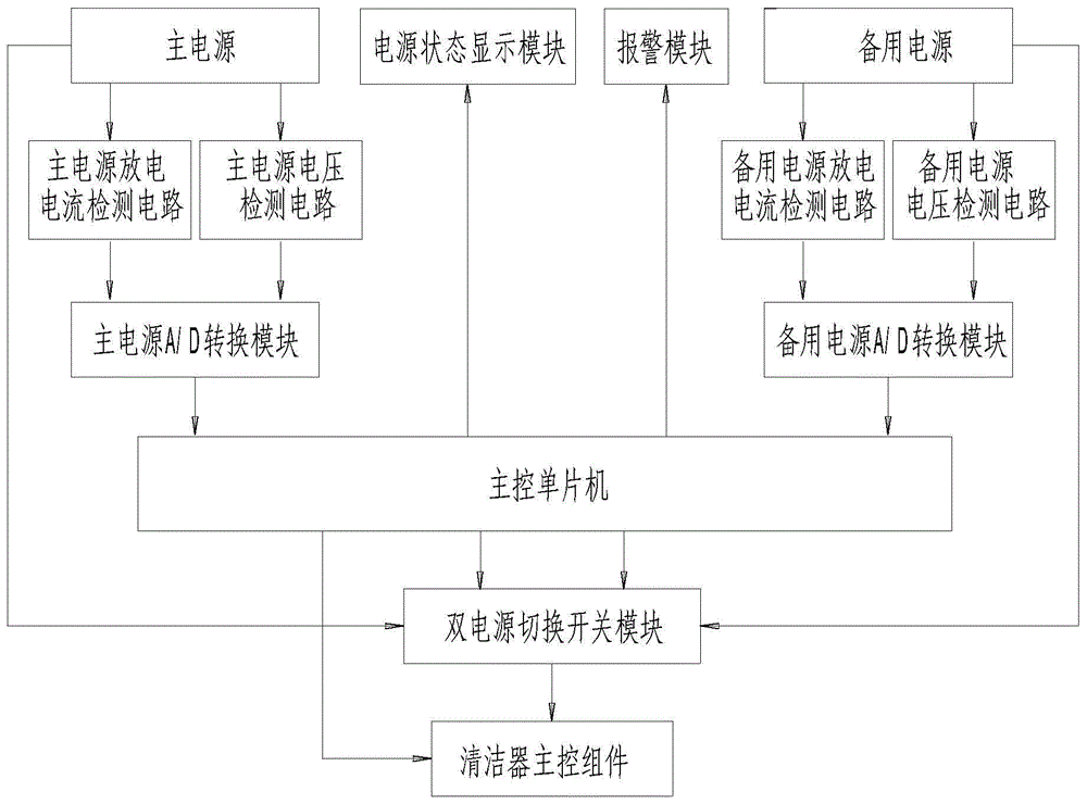
解决上述技术问题的技术方案是:一种具有双电源的玻璃清洁器,包括清洗器主控部件、行进部件、清洁部件、供电部件;所述的供电部件包括主电源、主电源放电电流检测电路、主电源电压检测电路、主电源A/D转换模块、备用电源、备用电源放电电流检测电路、备用电源电压检测电路、备用电源A/D转换模块、主控单片机、双电源切换开关模块,所述的主控单片机的输入端口通过主电源A/D转换模块分别连接主电源放电电流检测电路、主电源电压检测电路,主电源放电电流检测电路、主电源电压检测电路分别与主电源连接;所述的主控单片机的输入端口还通过备用电源A/D转换模块分别连接备用电源放电电流检测电路、备用电源电压检测电路,备用电源放电电流检测电路、备用电源电压检测电路分别与备用电源连接;主控单片机的输出端口与双电源切换开关模块的输入端口连接,双电源切换开关模块的输入端口还分别与主电源、备用电源连接,双电源切换开关模块的继电器常闭触点K1-2,K2-2分别与清洗器主控部件连接。The technical solution for solving the above technical problems is: a glass cleaner with dual power supplies, including a main control part of the washer, a traveling part, a cleaning part, and a power supply part; the power supply part includes a main power supply, a main power supply discharge current detection circuit , main power supply voltage detection circuit, main power A/D conversion module, backup power supply, backup power supply discharge current detection circuit, backup power supply voltage detection circuit, backup power supply A/D conversion module, main control microcontroller, dual power supply switch module, all The input port of the main control single-chip microcomputer is respectively connected to the main power supply discharge current detection circuit and the main power supply voltage detection circuit through the main power supply A/D conversion module, and the main power supply discharge current detection circuit and the main power supply voltage detection circuit are respectively connected to the main power supply; The input port of the main control microcontroller is also connected to the standby power supply discharge current detection circuit and the standby power supply voltage detection circuit respectively through the standby power supply A/D conversion module, and the standby power supply discharge current detection circuit and the standby power supply voltage detection circuit are respectively connected with the standby power supply; The output port of the main control microcontroller is connected with the input port of the dual power switch module, the input port of the dual power switch module is also connected with the main power supply and the backup power supply respectively, and the relay normally closed contacts K1-2 of the dual power switch module, K2-2 are respectively connected with the main control part of the cleaner.
本发明的进一步技术方案是:所述的主控单片机采用AT89C52单片机。The further technical scheme of the present invention is that: the main control single-chip microcomputer adopts AT89C52 single-chip microcomputer.
本发明的进一步技术方案是:所述的主电源包括主电池,该主电池通过充电器与市电连接进行充电;所述的备用电源包括备用电池,该备用电池通过太阳能充电模块进行充电。A further technical solution of the present invention is that: the main power source includes a main battery, which is connected to the mains through a charger for charging; the backup power source includes a backup battery, and the backup battery is charged by a solar charging module.
本发明的再进一步技术方案是:所述的太阳能充电模块包括太阳能电池板、太阳能充电控制电路和蓄电池,太阳能电池板通过太阳能充电控制电路与蓄电池连接;所述的太阳能电池板采用可折叠的柔性薄膜太阳能电池。A further technical solution of the present invention is: the solar charging module includes a solar panel, a solar charging control circuit and a battery, and the solar panel is connected to the battery through the solar charging control circuit; the solar panel adopts a foldable flexible Thin film solar cells.
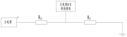
本发明的进一步技术方案是:所述的主电源电压检测电路包括阻值相同的主电源分压电阻RZ1、主电源分压电阻RZ2,主电源分压电阻RZ2的一端与主电源的正极连接,主电源分压电阻RZ2的另一端与主电源分压电阻RZ1连接,主电源分压电阻RZ1接地;所述的主电源A/D转换模块连接在主电源分压电阻RZ1、主电源分压电阻RZ2之间的电路上。A further technical solution of the present invention is: the main power supply voltage detection circuit comprises a main power supply voltage dividing resistor R Z1 and a main power supply voltage dividing resistor R Z2 with the same resistance value, and one end of the main power supply voltage dividing resistor R Z2 is connected to the main power supply voltage dividing resistor R Z2 . The positive pole is connected, the other end of the main power divider resistor R Z2 is connected to the main power divider resistor R Z1 , and the main power divider resistor R Z1 is grounded; the main power A/D conversion module is connected to the main power divider resistor R On the circuit between Z1 and the main power supply voltage dividing resistor R Z2 .
本发明的进一步技术方案是:所述的备用电源电压检测电路包括阻值相同备用电源分压电阻RB1、备用电源分压电阻RB2,备用电源分压电阻RB2的一端与备用电源的正极连接,备用电源分压电阻RB2的另一端与备用电源分压电阻RB1连接,备用电源分压电阻RB1接地;所述的备用电源A/D转换模块连接在备用电源分压电阻RB1、备用电源分压电阻RB2之间的电路上。A further technical solution of the present invention is: the backup power supply voltage detection circuit comprises a backup power supply voltage dividing resistor R B1 , a backup power supply voltage dividing resistor RB2 with the same resistance value, one end of the backup power supply voltage dividing resistor RB2 and the positive electrode of the backup power supply connection, the other end of the backup power divider resistor R B2 is connected to the backup power divider resistor R B1 , and the backup power divider resistor R B1 is grounded; the backup power A/D conversion module is connected to the backup power divider resistor R B1 , on the circuit between the backup power divider resistor RB2 .
本发明的进一步技术方案是:所述的双电源切换开关模块包括限流电阻R1、限流电阻R2,开关三极管T1、开关三极管T2,继电器K1、继电器K2和稳压二极管D1、稳压二极管D2;A further technical solution of the present invention is: the dual power switch module includes a current limiting resistor R1, a current limiting resistor R2, a switching transistor T1, a switching transistor T2, a relay K1, a relay K2, a zener diode D1, and a zener diode D2 ;
所述的开关三极管T1的基极经电阻R1连接到主控单片机的第一输出端口,开关三极管T1的发射极接地,开关三极管T1的集电极连接继电器K1的线圈K1-1,继电器K1的线圈K1-1接5伏电压并与稳压二极管D1两端连接;The base of the switching transistor T1 is connected to the first output port of the main control microcontroller through the resistor R1, the emitter of the switching transistor T1 is grounded, and the collector of the switching transistor T1 is connected to the coil K1-1 of the relay K1, and the coil of the relay K1 K1-1 is connected to 5 volts and connected to both ends of the Zener diode D1;
所述的开关三极管T2的基极经电阻R2连接到主控单片机的第二输出端口,开关三极管T2的发射极接地,开关三极管T2的集电极连接继电器K2的线圈K2-1,继电器K2的线圈K2-1接5伏电压并与稳压二极管D2两端连接;The base of the switching transistor T2 is connected to the second output port of the main control microcontroller through the resistor R2, the emitter of the switching transistor T2 is grounded, and the collector of the switching transistor T2 is connected to the coil K2-1 of the relay K2, and the coil of the relay K2 K2-1 is connected to 5V and is connected to both ends of the Zener diode D2;
继电器K1的常开触点K1-3依次连接主电源、继电器K2的常闭触点K2-2后连接清洗器主控部件;继电器K2的常开触点K2-3依次连接备用电源、继电器K1的常闭触点K1-2后连接清洗器主控部件。The normally open contacts K1-3 of the relay K1 are connected to the main power supply in turn, and the normally closed contacts K2-2 of the relay K2 are connected to the main control part of the cleaner; the normally open contacts K2-3 of the relay K2 are connected to the backup power supply and the relay K1 in turn. The normally closed contacts K1-2 are connected to the main control part of the cleaner.
本发明的再进一步技术方案是:所述的供电部件还包括有电源状态显示模块、报警模块,该电源状态显示模块、报警模块分别与主控单片机输出端口连接。A further technical solution of the present invention is that: the power supply component further includes a power supply state display module and an alarm module, and the power supply state display module and the alarm module are respectively connected to the output ports of the main control single-chip microcomputer.
本发明的另一技术方案是:一种具有双电源的玻璃清洁器的控制方法,该方法是通过主电源放电电流检测电路、主电源电压检测电路分别检测主电源的放电电流、放电电压数据,该主电源的放电电流、放电电压数据通过主电源A/D转换模块传输至主控单片机;同时还通过备用电源放电电流检测电路、备用电源电压检测电路分别检测备用电源的放电电流、放电电压数据,该备用电源的放电电流、放电电压数据通过备用电源A/D转换模块传输至主控单片机;由主控单片机将采集得到的主电源和备用电源的放电电流电压数值与设定的电流电压阈值进行对比,决定是否通过双电源切换开关模块启用备用电源,实现主电源与备用电源之间自动切换。Another technical solution of the present invention is: a control method for a glass cleaner with dual power supplies, the method is to detect the discharge current and discharge voltage data of the main power supply through the main power supply discharge current detection circuit and the main power supply voltage detection circuit, respectively, The discharge current and discharge voltage data of the main power supply are transmitted to the main control single-chip microcomputer through the main power supply A/D conversion module; at the same time, the discharge current and discharge voltage data of the backup power supply are respectively detected by the backup power supply discharge current detection circuit and the backup power supply voltage detection circuit. , the discharge current and discharge voltage data of the standby power supply are transmitted to the main control single-chip microcomputer through the standby power supply A/D conversion module; Make a comparison and decide whether to enable the backup power supply through the dual power switch module to realize automatic switching between the main power supply and the backup power supply.
本发明的进一步技术方案是:所述的由主控单片机将采集得到的主电源和备用电源的放电电流电压数值与设定的电流电压阈值进行对比,决定是否通过双电源切换开关模块启用备用电源的具体方法如下:A further technical scheme of the present invention is that: the main control single-chip computer compares the collected discharge current and voltage values of the main power supply and the backup power supply with the set current and voltage thresholds to determine whether to enable the backup power supply through the dual power switch module The specific method is as follows:
当主电源的放电电压或放电电流的数值正常时,主控单片机的第一输出端口输出高电平,经过限流电阻R1,控制开关三极管T1进入饱和状态,开关三极管T1接通,继电器K1的常开触点K1-3闭合,主电源到清洁器主控部件的通路形成,主电源给清洁器主控部件供电;当主电源的放电电压或放电电流的数值不在设定的阈值范围内时,主控单片机发出指令,主控单片机的第一输出端口输出低电平,第二输出端口输出高电平,经过限流电阻R2,控制开关三极管T2进入饱和状态,开关三极管T2接通,继电器K2的常开触点K2-3闭合,备用电源到清洁器主控部件的通路形成,备用电源给清洁器主控部件供电;当主电源和备用电源和的放电电压或放电电流的数值不在设定的阈值范围内时,主控单片机发出指令,控制报警模块通知用户,同时通知清洁器主控组件控制玻璃清洁器停止工作,返回充电。When the value of the discharge voltage or discharge current of the main power supply is normal, the first output port of the main control microcontroller outputs a high level, and through the current limiting resistor R1, the switching transistor T1 is controlled to enter a saturated state, the switching transistor T1 is turned on, and the relay K1 is always on. The open contacts K1-3 are closed, and the path from the main power supply to the main control part of the cleaner is formed, and the main power supply supplies power to the main control part of the cleaner; when the value of the discharge voltage or discharge current of the main power supply is not within the set threshold range, the main power supply The control microcontroller sends an instruction, the first output port of the main control microcontroller outputs a low level, and the second output port outputs a high level. After passing through the current limiting resistor R2, the switching transistor T2 is controlled to enter a saturated state, the switching transistor T2 is turned on, and the relay K2 is turned on. The normally open contact K2-3 is closed, the passage from the backup power supply to the main control part of the cleaner is formed, and the backup power supply supplies power to the main control part of the cleaner; when the value of the discharge voltage or discharge current of the main power supply and the backup power supply is not within the set threshold When it is within the range, the main control single-chip microcomputer sends an instruction to control the alarm module to notify the user, and at the same time notify the main control component of the cleaner to control the glass cleaner to stop working and return to charging.
由于采用上述结构,本发明之具有双电源的玻璃清洁器及其控制方法与现有技术相比,具有以下有益效果:Compared with the prior art, the glass cleaner with dual power supply and the control method thereof of the present invention have the following beneficial effects due to the adoption of the above structure:
1.可实现双电源自动切换:1. It can realize automatic switching of dual power supply:
由于本发明的供电部件包括主电源、主电源放电电流检测电路、主电源电压检测电路、备用电源、备用电源放电电流检测电路、备用电源电压检测电路、主控单片机、双电源切换开关模块等;使用时,通过主电源放电电流检测电路、主电源电压检测电路分别检测主电源的放电电流、放电电压数据,该主电源的放电电流、放电电压数据通过主电源A/D转换模块传输至主控单片机;同时还通过备用电源放电电流检测电路、备用电源电压检测电路分别检测备用电源的放电电流、放电电压数据,该备用电源的放电电流、放电电压数据通过备用电源A/D转换模块传输至主控单片机;由主控单片机将采集得到的主电源和备用电源的放电电流电压数值与设定的电流电压阈值进行对比,决定是否通过双电源切换开关模块启用备用电源。因此,本发明可实现双电源的自动切换。Because the power supply component of the present invention includes a main power supply, a main power supply discharge current detection circuit, a main power supply voltage detection circuit, a backup power supply, a backup power supply discharge current detection circuit, a backup power supply voltage detection circuit, a main control single-chip microcomputer, a dual power supply switch module, and the like; When in use, the discharge current and discharge voltage data of the main power supply are respectively detected by the main power supply discharge current detection circuit and the main power supply voltage detection circuit, and the discharge current and discharge voltage data of the main power supply are transmitted to the main control through the main power supply A/D conversion module. At the same time, the discharge current and discharge voltage data of the standby power supply are respectively detected by the standby power supply discharge current detection circuit and the standby power supply voltage detection circuit. The discharge current and discharge voltage data of the standby power supply are transmitted to the main The main control microcontroller compares the collected discharge current and voltage values of the main power supply and the backup power supply with the set current and voltage thresholds, and decides whether to enable the backup power supply through the dual power switch module. Therefore, the present invention can realize automatic switching of dual power sources.
2.可满足玻璃清洁器大面积清洗过程的需要:2. It can meet the needs of the large-area cleaning process of glass cleaners:
由于本发明的清洁器可实现双电源自动切换,当主电源供电不足时,主控单片机控制双电源切换开关模块启用备用电源,使玻璃清洁器继续工作。当主电源与备用电源的电量都进入低于一定阈值的状态,不足以使得清洁器继续运行工作时,主控单片机通过报警模块通知用户,同时通知清洁器主控组件控制玻璃清洁器返回充电。因此,本发明通过双电源方式供电,确保玻璃清洁器的持续供电,可满足玻璃清洁器大面积清洗过程的需要。Because the cleaner of the present invention can realize automatic switching of dual power sources, when the main power supply is insufficient, the main control single-chip microcomputer controls the dual power switch module to activate the backup power supply, so that the glass cleaner continues to work. When the power of the main power supply and the backup power supply is lower than a certain threshold, which is not enough to keep the cleaner running, the main control microcontroller notifies the user through the alarm module, and at the same time notifies the main control component of the cleaner to control the glass cleaner to return to charging. Therefore, the present invention supplies power by means of dual power sources, ensures continuous power supply of the glass cleaner, and can meet the needs of the large-area cleaning process of the glass cleaner.
3. 清洁环保、智能化程度高:3. Clean, environmentally friendly and highly intelligent:
由于本发明的备用电源采用太阳能供电方式,具有清洁环保的特点。同时本发明还采用主控单片机对电源的状态进行自动识别,智能地管理电源的应用过程,充分利用太阳能的同时,保证玻璃清洁器的智能供电,其智能化程度较高。Since the backup power supply of the present invention adopts the solar power supply mode, it has the characteristics of cleanliness and environmental protection. At the same time, the invention also adopts the main control single-chip microcomputer to automatically identify the state of the power supply, intelligently manages the application process of the power supply, fully utilizes the solar energy, and ensures the intelligent power supply of the glass cleaner with a high degree of intelligence.
4.可提高清洁玻璃的效率:4. It can improve the efficiency of cleaning glass:
由于本发明可实现双电源自动切换,当主电源供电不足时,应用已经充电的备用电池可以使得玻璃清洁器不会停止工作,且能及时返回。双电源互为补充,有效保证了玻璃清洁器的正常工作,提高了清洁玻璃的效率,易于推广使用。Since the invention can realize automatic switching of dual power sources, when the main power supply is insufficient, the use of a charged backup battery can make the glass cleaner not stop working and return in time. The dual power supplies complement each other, effectively ensure the normal operation of the glass cleaner, improve the efficiency of glass cleaning, and are easy to popularize and use.
下面,结合附图和实施例对本发明之具有双电源的玻璃清洁器及其控制方法的技术特征作进一步的说明。Hereinafter, the technical features of the glass cleaner with dual power sources and the control method thereof of the present invention will be further described with reference to the accompanying drawings and embodiments.
附图说明Description of drawings
图1:实施例一所述本发明之具有双电源的玻璃清洁器的结构框图,Fig. 1: The structural block diagram of the glass cleaner with dual power sources of the present invention according to the first embodiment,
图2:实施例一所述太阳能充电器的组成框图,Figure 2: The composition block diagram of the solar charger according to the first embodiment,
图3:实施例一所述主电源电压检测电路的电路图,Figure 3: The circuit diagram of the main power supply voltage detection circuit according to the first embodiment,
图4:实施例一所述备用电源电压检测电路的电路图,Figure 4: The circuit diagram of the backup power supply voltage detection circuit according to the first embodiment,
图5:实施例一所述双电源切换开关模块的电路图,Figure 5: The circuit diagram of the dual power switch module according to the first embodiment,
图6:实施例二中,采用双电源切换开关模块进行双电源切换的流程图。FIG. 6 : In the second embodiment, a flow chart of switching between dual power supplies using a dual power supply switch module.
具体实施方式Detailed ways
实施例一:Example 1:
一种具有双电源的玻璃清洁器,包括清洗器主控部件、行进部件、清洁部件、供电部件;所述的行进部件主要由直流电机驱动的转动轴承以及与转动轴承连接的驱动轮子组成。A glass cleaner with dual power sources includes a cleaner main control part, a traveling part, a cleaning part, and a power supply part; the traveling part is mainly composed of a rotating bearing driven by a DC motor and a driving wheel connected with the rotating bearing.
所述的供电部件包括主电源、主电源放电电流检测电路、主电源电压检测电路、主电源A/D转换模块、备用电源、备用电源放电电流检测电路、备用电源电压检测电路、备用电源A/D转换模块、主控单片机、双电源切换开关模块、电源状态显示模块、报警模块;其中,The power supply components include a main power supply, a main power supply discharge current detection circuit, a main power supply voltage detection circuit, a main power supply A/D conversion module, a backup power supply, a backup power supply discharge current detection circuit, a backup power supply voltage detection circuit, and a backup power supply A/D D conversion module, main control microcontroller, dual power switch module, power status display module, alarm module; among them,
所述的主控单片机的输入端口通过主电源A/D转换模块分别连接主电源放电电流检测电路、主电源电压检测电路,主电源放电电流检测电路、主电源电压检测电路分别与主电源连接;所述的主控单片机的输入端口还通过备用电源A/D转换模块分别连接备用电源放电电流检测电路、备用电源电压检测电路,备用电源放电电流检测电路、备用电源电压检测电路分别与备用电源连接;主控单片机的输出端口与双电源切换开关模块的输入端口连接,双电源切换开关模块的输入端口还分别与主电源、备用电源连接,双电源切换开关模块的继电器常闭触点与清洗器主控部件连接,主控单片机与清洗器主控部件、电源状态显示模块、报警模块连接。The input port of the main control single-chip microcomputer is respectively connected to the main power supply discharge current detection circuit and the main power supply voltage detection circuit through the main power supply A/D conversion module, and the main power supply discharge current detection circuit and the main power supply voltage detection circuit are respectively connected to the main power supply; The input port of the main control microcontroller is also connected to the standby power supply discharge current detection circuit and the standby power supply voltage detection circuit respectively through the standby power supply A/D conversion module, and the standby power supply discharge current detection circuit and the standby power supply voltage detection circuit are respectively connected to the standby power supply. ; The output port of the main control microcontroller is connected to the input port of the dual power switch module, the input port of the dual power switch module is also connected to the main power supply and the backup power supply respectively, and the relay normally closed contact of the dual power switch module is connected to the cleaner. The main control part is connected, and the main control single-chip microcomputer is connected with the main control part of the cleaner, the power state display module and the alarm module.
所述的主控单片机作为控制中心器件,选用通用的AT89C52单片机。The main control single-chip microcomputer is used as the control center device, and the general-purpose AT89C52 single-chip microcomputer is selected.
所述的主电源包括主电池,该主电池通过充电器与市电连接进行充电;The main power source includes a main battery, and the main battery is connected with the commercial power through a charger for charging;
所述的备用电源包括备用电池,该备用电池通过太阳能充电模块进行充电。所述的太阳能充电模块包括太阳能电池板、太阳能充电控制电路和蓄电池,太阳能电池板覆盖在玻璃清洁器的表面,该太阳能电池板通过太阳能充电控制电路与蓄电池连接;太阳能电池板实现太阳能到电能的光伏转换,然后通过充电控制电路进行处理后,将电充到蓄电池上。太阳能电池板采用可折叠的柔性薄膜太阳能电池,当机器充电或者开始工作前,可打开太阳能电池板,打开的太阳能电池板覆盖在玻璃清洁器表面上,可以遮挡太阳光;当机器停止工作时,可以把电池板折叠起来,以便存放。The backup power source includes a backup battery, and the backup battery is charged by a solar charging module. The solar charging module includes a solar panel, a solar charging control circuit and a battery, the solar panel covers the surface of the glass cleaner, and the solar panel is connected to the battery through the solar charging control circuit; the solar panel realizes the conversion of solar energy to electric energy. Photovoltaic conversion is then processed through the charge control circuit to charge the battery. The solar panel adopts foldable flexible thin-film solar cells. When the machine is charging or starting to work, the solar panel can be opened, and the opened solar panel covers the surface of the glass cleaner to block sunlight; when the machine stops working, The panels can be folded up for storage.
所述的太阳能充电控制电路,采用太阳能充电管理集成电路BQ24650,实现自动控制和管理太阳能电池板对蓄电池的充电;该太阳能充电控制电路主要通过芯片UC3906和外围电路组成,可有效防止电池的充放电中出现的浮充、反充和过充;The solar charging control circuit adopts the solar charging management integrated circuit BQ24650 to realize automatic control and management of the charging of the battery by the solar panel; the solar charging control circuit is mainly composed of the chip UC3906 and the peripheral circuit, which can effectively prevent the charging and discharging of the battery. Float charge, reverse charge and overcharge appear in;
为了便于携带,所述的蓄电池选用锂电池。For the convenience of carrying, the storage battery is a lithium battery.
通过主控单片机控制放电过程中主电源和备用电源的欠压放电和过流放电,可延长电池的寿命。The main control single-chip microcomputer controls the undervoltage discharge and overcurrent discharge of the main power supply and the backup power supply during the discharge process, which can prolong the life of the battery.
所述的主电源放电电流检测电路、备用电源放电电流检测电路均是在主电源或备用电源与负载的干路上串联一个很小阻值的精密电阻,然后把精密电阻上的电压通过主电源或备用电源A/D转换模块转换接到主控单片机,根据I=U/R,可以计算出来精密电阻的通过的电流,也就是电源放电时的电流。The main power supply discharge current detection circuit and the backup power supply discharge current detection circuit are all connected in series with a small resistance precision resistor on the main power supply or backup power supply and the main circuit of the load, and then the voltage on the precision resistor is passed through the main power supply or the load. The standby power supply A/D conversion module is converted and connected to the main control single-chip microcomputer. According to I=U/R, the current passing through the precision resistor can be calculated, that is, the current when the power supply is discharged.
所述的主电源电压检测电路包括阻值相同的主电源分压电阻RZ1、主电源分压电阻RZ2,主电源分压电阻RZ2的一端与主电源的正极连接,主电源分压电阻RZ2的另一端与主电源分压电阻RZ1连接,主电源分压电阻RZ1接地;所述的主电源A/D转换模块连接在主电源分压电阻RZ1、主电源分压电阻RZ2之间的电路上。The main power supply voltage detection circuit includes a main power supply voltage divider resistor R Z1 and a main power supply voltage divider resistor R Z2 with the same resistance value. One end of the main power supply voltage divider resistor R Z2 is connected to the positive pole of the main power supply. The other end of R Z2 is connected to the main power voltage dividing resistor R Z1 , and the main power voltage dividing resistor R Z1 is grounded; the main power A/D conversion module is connected to the main power voltage dividing resistor R Z1 and the main power voltage dividing resistor R on the circuit between Z2 .
所述的备用电源电压检测电路包括阻值相同备用电源分压电阻RB1、备用电源分压电阻RB2,备用电源分压电阻RB2的一端与备用电源的正极连接,备用电源分压电阻RB2的另一端与备用电源分压电阻RB1连接,备用电源分压电阻RB1接地;所述的备用电源A/D转换模块连接在备用电源分压电阻RB1、备用电源分压电阻RB2之间的电路上。The backup power supply voltage detection circuit includes a backup power supply voltage dividing resistor R B1 and a backup power supply voltage dividing resistor R B2 with the same resistance value . The other end of B2 is connected to the backup power divider resistor R B1 , and the backup power divider resistor R B1 is grounded; the backup power A/D conversion module is connected to the backup power divider resistor R B1 and the backup power divider resistor R B2 on the circuit between.
在上述主电源电压检测电路中,设主电源的总电压为U,所述RZ1上的电压为U1,RZ2上的电压为U2,把RZ1的电压U1经主电源A/D转换模块转换连接到主控单片机的输入端,再通过公式U=U1+(RZ2/ RZ1)U1计算得到所述主电源的总电压。同理,可通过同样的方法计算得到备用电源的总电压。In the above main power supply voltage detection circuit, the total voltage of the main power supply is U, the voltage on the R Z1 is U1, the voltage on the R Z2 is U2, and the voltage U1 of the R Z1 is passed through the main power A/D conversion module. The conversion is connected to the input terminal of the main control microcontroller, and then the total voltage of the main power supply is calculated by the formula U=U1+(R Z2 / R Z1 ) U1. In the same way, the total voltage of the backup power supply can be calculated by the same method.
所述的双电源切换开关模块包括限流电阻R1、限流电阻R2,开关三极管T1、开关三极管T2,继电器K1、继电器K2和稳压二极管D1、稳压二极管D2;The dual power switch module includes a current limiting resistor R1, a current limiting resistor R2, a switching transistor T1, a switching transistor T2, a relay K1, a relay K2, a zener diode D1, and a zener diode D2;
所述的开关三极管T1采用NPN型的开关三极管,该开关三极管T1的基极经电阻R1连接到主控单片机的第一输出端口P2.1,开关三极管T1的发射极接地,开关三极管T1的集电极连接继电器K1的线圈K1-1,继电器K1的线圈K1-1接5伏电压并与稳压二极管D1两端连接;The switching transistor T1 is an NPN type switching transistor, the base of the switching transistor T1 is connected to the first output port P2.1 of the main control microcontroller through the resistor R1, the emitter of the switching transistor T1 is grounded, and the collector of the switching transistor T1 is grounded. The electrode is connected to the coil K1-1 of the relay K1, and the coil K1-1 of the relay K1 is connected to a voltage of 5 volts and is connected to both ends of the zener diode D1;
所述的开关三极管T2采用NPN型的开关三极管,该开关三极管T2的基极经电阻R2连接到主控单片机的第二输出端口P2.2,开关三极管T2的发射极接地,开关三极管T2的集电极连接继电器K2的线圈K2-1,继电器K2的线圈K2-1接5伏电压并与稳压二极管D2两端连接;The switch transistor T2 is an NPN type switch transistor, the base of the switch transistor T2 is connected to the second output port P2.2 of the main control microcontroller through the resistor R2, the emitter of the switch transistor T2 is grounded, and the collector of the switch transistor T2 is grounded. The electrode is connected to the coil K2-1 of the relay K2, and the coil K2-1 of the relay K2 is connected to 5 volts and connected to both ends of the zener diode D2;
继电器K1的常开触点K1-3依次连接主电源、继电器K2的常闭触点K2-2后连接清洗器主控部件;继电器K2的常开触点K2-3依次连接备用电源、继电器K1的常闭触点K1-2后连接清洗器主控部件。所述的继电器K1与继电器K2形成互锁,备用电源与主电源不会同时供电。主电源与备用电源均正常供电优先采用主电源供电。The normally open contacts K1-3 of the relay K1 are connected to the main power supply in turn, and the normally closed contacts K2-2 of the relay K2 are connected to the main control part of the cleaner; the normally open contacts K2-3 of the relay K2 are connected to the backup power supply and the relay K1 in turn. The normally closed contacts K1-2 are connected to the main control part of the cleaner. The relay K1 and the relay K2 are interlocked, and the backup power supply and the main power supply will not supply power at the same time. Both the main power supply and the backup power supply are normally powered, and the main power supply is preferred.
所述的电源状态显示模块用于直观的显示当前的电源状态,该电源状态显示模块采用LCD1602字符型液晶显示模块,将主电源和备用电源的电流电压以滚动的方式在液晶显示模块上进行显示,使用者可以根据显示的电流电压值,对电源进行更好的管理。The power status display module is used to visually display the current power status. The power status display module adopts an LCD1602 character type liquid crystal display module, and displays the current and voltage of the main power supply and the backup power supply on the liquid crystal display module in a rolling manner. , the user can better manage the power supply according to the displayed current and voltage values.
实施例二:Embodiment 2:
一种具有双电源的玻璃清洁器的控制方法,该方法是通过主电源放电电流检测电路、主电源电压检测电路分别检测主电源的放电电流、放电电压数据,该主电源的放电电流、放电电压数据通过主电源A/D转换模块传输至主控单片机;同时还通过备用电源放电电流检测电路、备用电源电压检测电路分别检测备用电源的放电电流、放电电压数据,该备用电源的放电电流、放电电压数据通过备用电源A/D转换模块传输至主控单片机;由主控单片机将采集得到的主电源和备用电源的放电电流电压数值与设定的电流电压阈值进行对比,决定是否通过双电源切换开关模块启用备用电源,实现主电源与备用电源之间自动切换。A control method for a glass cleaner with dual power supplies, the method is to detect the discharge current and discharge voltage data of the main power supply through a main power supply discharge current detection circuit and a main power supply voltage detection circuit, respectively, and the discharge current and discharge voltage of the main power supply. The data is transmitted to the main control single-chip microcomputer through the main power A/D conversion module; at the same time, the discharge current and discharge voltage data of the backup power supply are respectively detected by the backup power supply discharge current detection circuit and the backup power supply voltage detection circuit. The voltage data is transmitted to the main control microcontroller through the backup power supply A/D conversion module; the main control microcontroller compares the collected discharge current and voltage values of the main power supply and the backup power supply with the set current and voltage thresholds to decide whether to switch between the dual power supplies. The switch module enables the backup power supply and realizes automatic switching between the main power supply and the backup power supply.
所述的由主控单片机将采集得到的主电源和备用电源的放电电流电压数值与设定的电流电压阈值进行对比,决定是否通过双电源切换开关模块启用备用电源的具体方法如下:The specific method of determining whether to enable the backup power supply through the dual power switch module is as follows:
当主电源的放电电压或放电电流的数值正常时,主控单片机的第一输出端口输出5V高电平,经过限流电阻R1,控制开关三极管T1进入饱和状态,开关三极管T1接通,继电器K1的常开触点K1-3闭合,主电源到清洁器主控部件的通路形成,主电源给清洁器主控部件供电;当主电源的放电电压或放电电流的数值不在设定的阈值范围内时,主控单片机发出指令,主控单片机的第一输出端口P2.1输出低电平,第二输出端口P2.2输出高电平,经过限流电阻R2,控制开关三极管T2进入饱和状态,开关三极管T2接通,继电器K2的常开触点K2-3闭合,备用电源到清洁器主控部件的通路形成,备用电源给清洁器主控部件供电;当主电源与备用电源的放电电压或放电电流的数值都不在设定的阈值范围内时,主控单片机发出指令,控制报警模块通知用户,同时通知清洁器主控组件控制玻璃清洁器返回充电。When the value of the discharge voltage or discharge current of the main power supply is normal, the first output port of the main control single-chip microcomputer outputs a high level of 5V, and through the current limiting resistor R1, the switching transistor T1 is controlled to enter a saturated state, the switching transistor T1 is turned on, and the relay K1 is turned on. The normally open contacts K1-3 are closed, the main power supply to the main control part of the cleaner is formed, and the main power supply supplies power to the main control part of the cleaner; when the value of the discharge voltage or discharge current of the main power supply is not within the set threshold range, The main control microcontroller sends an instruction, the first output port P2.1 of the main control microcontroller outputs a low level, and the second output port P2.2 outputs a high level. After the current limiting resistor R2, the switching transistor T2 is controlled to enter the saturation state, and the switching transistor T2 is turned on, the normally open contacts K2-3 of the relay K2 are closed, the passage from the backup power supply to the main control part of the cleaner is formed, and the backup power supply supplies power to the main control part of the cleaner; When the values are not within the set threshold range, the main control single-chip microcomputer sends an instruction to control the alarm module to notify the user, and at the same time inform the cleaner main control component to control the glass cleaner to return to charging.
Claims (5)
Priority Applications (1)
| Application Number | Priority Date | Filing Date | Title |
|---|---|---|---|
| CN201611170776.3A CN106618405B (en) | 2016-12-16 | 2016-12-16 | Glass cleaner with dual power supplies and control method thereof |
Applications Claiming Priority (1)
| Application Number | Priority Date | Filing Date | Title |
|---|---|---|---|
| CN201611170776.3A CN106618405B (en) | 2016-12-16 | 2016-12-16 | Glass cleaner with dual power supplies and control method thereof |
Publications (2)
| Publication Number | Publication Date |
|---|---|
| CN106618405A CN106618405A (en) | 2017-05-10 |
| CN106618405B true CN106618405B (en) | 2022-08-16 |
Family
ID=58822201
Family Applications (1)
| Application Number | Title | Priority Date | Filing Date |
|---|---|---|---|
| CN201611170776.3A Active CN106618405B (en) | 2016-12-16 | 2016-12-16 | Glass cleaner with dual power supplies and control method thereof |
Country Status (1)
| Country | Link |
|---|---|
| CN (1) | CN106618405B (en) |
Families Citing this family (5)
| Publication number | Priority date | Publication date | Assignee | Title |
|---|---|---|---|---|
| CN106972622B (en) * | 2017-05-24 | 2023-11-28 | 江阴元灵芯旷微电子技术有限公司 | Control circuit and chip of dual-power switch path |
| CN108899981B (en) * | 2018-08-01 | 2021-04-30 | 广州番禺巨大汽车音响设备有限公司 | High-efficiency storage battery power supply method and device for large-scale sound equipment |
| CN108670114A (en) * | 2018-08-15 | 2018-10-19 | 中国联合网络通信集团有限公司 | A kind of window cleaning device and its wipe window method |
| CN112271805A (en) * | 2020-11-02 | 2021-01-26 | 珠海格力电器股份有限公司 | Power supply switching circuit, power supply switching method, wire controller and air conditioning equipment |
| CN113746196B (en) * | 2021-09-02 | 2023-05-12 | 苏州热工研究院有限公司 | Nuclear power plant emergency power supply control system and method |
Citations (6)
| Publication number | Priority date | Publication date | Assignee | Title |
|---|---|---|---|---|
| DE3902647A1 (en) * | 1989-01-21 | 1990-08-02 | Interlava Ag | DEVICE FOR AUTOMATIC SUCTION POWER CONTROL OF A VACUUM CLEANER |
| CN200969694Y (en) * | 2006-10-10 | 2007-10-31 | 沈阳斯凯光电科技发展有限公司 | Duplicate supply automatic switching LED corridor inductive illuminating apparatus |
| CN101841184A (en) * | 2010-03-12 | 2010-09-22 | 英华达(南京)科技有限公司 | Power supply switching device and method thereof |
| CN104218667A (en) * | 2014-09-25 | 2014-12-17 | 无锡昊瑜节能环保设备有限公司 | Power saving and supplying system of high-rise building |
| CN204520510U (en) * | 2015-02-13 | 2015-08-05 | 广西科技大学鹿山学院 | Can the safe and intelligent device for cleaning glass of crossing over blockage |
| CN206659762U (en) * | 2016-12-16 | 2017-11-24 | 广西科技大学鹿山学院 | Device for cleaning glass with dual power supply |
-
2016
- 2016-12-16 CN CN201611170776.3A patent/CN106618405B/en active Active
Patent Citations (6)
| Publication number | Priority date | Publication date | Assignee | Title |
|---|---|---|---|---|
| DE3902647A1 (en) * | 1989-01-21 | 1990-08-02 | Interlava Ag | DEVICE FOR AUTOMATIC SUCTION POWER CONTROL OF A VACUUM CLEANER |
| CN200969694Y (en) * | 2006-10-10 | 2007-10-31 | 沈阳斯凯光电科技发展有限公司 | Duplicate supply automatic switching LED corridor inductive illuminating apparatus |
| CN101841184A (en) * | 2010-03-12 | 2010-09-22 | 英华达(南京)科技有限公司 | Power supply switching device and method thereof |
| CN104218667A (en) * | 2014-09-25 | 2014-12-17 | 无锡昊瑜节能环保设备有限公司 | Power saving and supplying system of high-rise building |
| CN204520510U (en) * | 2015-02-13 | 2015-08-05 | 广西科技大学鹿山学院 | Can the safe and intelligent device for cleaning glass of crossing over blockage |
| CN206659762U (en) * | 2016-12-16 | 2017-11-24 | 广西科技大学鹿山学院 | Device for cleaning glass with dual power supply |
Non-Patent Citations (1)
| Title |
|---|
| 基于单片机的双电源切换装置的设计与实现;薛燕红;《微型电脑应用》;20070920;第23卷(第09期);第24-25页 * |
Also Published As
| Publication number | Publication date |
|---|---|
| CN106618405A (en) | 2017-05-10 |
Similar Documents
| Publication | Publication Date | Title |
|---|---|---|
| CN106618405B (en) | Glass cleaner with dual power supplies and control method thereof | |
| CN202134942U (en) | A wind-solar hybrid energy storage power supply control system | |
| CN210577925U (en) | Novel emergency guarantee system for lead-acid storage battery | |
| CN206850457U (en) | A kind of charging wake-up circuit and system applied to battery management system | |
| CN206742952U (en) | LED emergency power supplies are met an urgent need switching circuit | |
| CN206659762U (en) | Device for cleaning glass with dual power supply | |
| CN206362841U (en) | Long-life intelligent electric energy meter based on super capacitor and button-shaped lithium-manganese cell | |
| CN100459368C (en) | Single battery or sub battery group protection circuit and method and device for controlling power type battery group uniformly discharging | |
| CN102416881B (en) | Interlocking structure of power battery pack | |
| CN104022563B (en) | The double cell group commutation circuit of electric vehicle | |
| CN205388997U (en) | Module detection device of secondary lithium battery group | |
| CN107591886A (en) | A kind of robot power control module | |
| CN205430123U (en) | Solar energy is to charge controllers of load | |
| CN205406671U (en) | Load detection circuitry | |
| CN202838662U (en) | Remote controller | |
| CN203481896U (en) | All power-off charger for electric vehicle | |
| CN202872443U (en) | Fuel-cell-based communication power supply | |
| CN103078369B (en) | Lithium battery power shortage active device | |
| CN207866998U (en) | A kind of accumulator cell charging and discharging on-line monitoring system | |
| CN202573850U (en) | A power battery pack interlocking structure | |
| CN206149132U (en) | Switching power supply shutdown rapid discharging circuit based on resistance -capacitance reduction voltage circuit | |
| CN200987080Y (en) | Solar energy notebook computer power supply device | |
| CN206884766U (en) | A kind of cell management system of electric automobile based on ARM9 | |
| CN202997648U (en) | Lithium-battery electric-loss activation apparatus | |
| CN107834622A (en) | A kind of lithium battery activates control system automatically |
Legal Events
| Date | Code | Title | Description |
|---|---|---|---|
| PB01 | Publication | ||
| PB01 | Publication | ||
| SE01 | Entry into force of request for substantive examination | ||
| SE01 | Entry into force of request for substantive examination | ||
| GR01 | Patent grant | ||
| GR01 | Patent grant | ||
| CP03 | Change of name, title or address |
Address after: No.99 Xinliu Avenue, Yufeng District, Liuzhou City, Guangxi Zhuang Autonomous Region Patentee after: Liuzhou Institute of Technology Address before: 545616 No.99 Xinliu Avenue, Liuzhou City, Guangxi Zhuang Autonomous Region Patentee before: Liuzhou Institute of Technology |
|
| CP03 | Change of name, title or address | ||
| TR01 | Transfer of patent right |
Effective date of registration: 20230628 Address after: 545000 No.705, building 2, Guantang R & D center, No.10 Shuangren Road, Liuzhou City, Guangxi Zhuang Autonomous Region (entrusted by Liuzhou Gaochuang business secretary Co., Ltd.) Patentee after: Liuzhou Jixun Cloud Technology Co.,Ltd. Address before: No.99 Xinliu Avenue, Yufeng District, Liuzhou City, Guangxi Zhuang Autonomous Region Patentee before: Liuzhou Institute of Technology |
|
| TR01 | Transfer of patent right | ||
| CP03 | Change of name, title or address |
Address after: Building 4, Yuexin Park, Chongwen Town, Jinghe New City, Xixian New Area, Xi'an City, Shaanxi Province 710000, 2014 Patentee after: Shaanxi Jixun Cloud Technology Co.,Ltd. Country or region after: China Address before: 545000 No.705, building 2, Guantang R & D center, No.10 Shuangren Road, Liuzhou City, Guangxi Zhuang Autonomous Region (entrusted by Liuzhou Gaochuang business secretary Co., Ltd.) Patentee before: Liuzhou Jixun Cloud Technology Co.,Ltd. Country or region before: China |
|
| CP03 | Change of name, title or address |