CN1066117C - Method and apparatus for converting an open top container into a top discharge container - Google Patents
Method and apparatus for converting an open top container into a top discharge container Download PDFInfo
- Publication number
- CN1066117C CN1066117C CN97196354A CN97196354A CN1066117C CN 1066117 C CN1066117 C CN 1066117C CN 97196354 A CN97196354 A CN 97196354A CN 97196354 A CN97196354 A CN 97196354A CN 1066117 C CN1066117 C CN 1066117C
- Authority
- CN
- China
- Prior art keywords
- container
- frame
- open
- lid
- closure member
- Prior art date
- Legal status (The legal status is an assumption and is not a legal conclusion. Google has not performed a legal analysis and makes no representation as to the accuracy of the status listed.)
- Expired - Fee Related
Links
Images


Classifications
-
- B—PERFORMING OPERATIONS; TRANSPORTING
- B65—CONVEYING; PACKING; STORING; HANDLING THIN OR FILAMENTARY MATERIAL
- B65G—TRANSPORT OR STORAGE DEVICES, e.g. CONVEYORS FOR LOADING OR TIPPING, SHOP CONVEYOR SYSTEMS OR PNEUMATIC TUBE CONVEYORS
- B65G65/00—Loading or unloading
- B65G65/23—Devices for tilting and emptying of containers
Landscapes
- Engineering & Computer Science (AREA)
- Mechanical Engineering (AREA)
- Control And Other Processes For Unpacking Of Materials (AREA)
- Refuse Receptacles (AREA)
- Basic Packing Technique (AREA)
- Closures For Containers (AREA)
Abstract
Description
发明领域field of invention
本发明总的涉及将容器排空,尤其涉及将容器安置在准备排空状态。The present invention relates generally to emptying containers, and more particularly to placing containers in a ready-to-empty state.
本发明已经创造了这类容器,它包括一个具有4个直立的联锁边的托架或底座。尽管本发明已经创造了上述形式的容器,但不限于这些容器。The present inventors have created such containers which comprise a bracket or base with 4 upstanding interlocking sides. Although the present invention has created containers of the form described above, it is not limited to these containers.
发明的背景background of the invention
当容器必须要排空时,所采用的方法在很大程度上取决于容器的内装物。在可流动的非液体物质如细颗粒物的情况下,重力出料是优选的方案。为了使这种形式出料更方便,已经设法研制具有底部出料装置的容器。由于许多原因,装在一个底座或托架中(它们构成容器的一部分)中的具有底部出料的各种容器未发现受到用户的欢迎。When a container must be emptied, the method used depends largely on the contents of the container. In the case of flowable non-liquid materials such as fine particulate matter, gravity discharge is the preferred solution. In order to make this form of discharge more convenient, attempts have been made to develop containers with bottom discharge devices. Various containers with bottom discharges housed in a base or tray (which form part of the container) have not found popularity with users for a number of reasons.
一种替代方法是,通常在一个容器安装于其上的倾斜装置中,将该容器倾斜到使内装物能从容器中流出所需要的程度。为了提供一种大致均匀的出料速率,这是正常的要求,容器的倾斜须被连续地调节。这种出料方法是费力的和/或时间集中的,因此不受欢迎。An alternative is to tilt the container to the extent required to enable the contents to flow from the container, usually in a tilting device to which the container is mounted. In order to provide an approximately uniform discharge rate, which is a normal requirement, the inclination of the container must be continuously adjusted. This method of discharging is laborious and/or time intensive and therefore undesirable.
发明概述Summary of the invention
一般说来,本发明提供一种容器颠倒方法,该方法包括通过安装一个容器罩然后将该容器倒置等步骤,将一个顶部开口的容器安置成处于一种准备出料的状态,该容器罩在容器顶部开口的上方设置一个出料口。通过该出料口的出料能够很容易地用改变出料口的大小来调整。这里还公开了用于经济而有效地实施该方法的设备。In general, the present invention provides a container inversion method comprising placing an open-top container in a ready-to-discharge state by installing a container cover and then inverting the container. A discharge port is arranged above the top opening of the container. The discharge through the discharge port can be easily adjusted by changing the size of the discharge port. Apparatus for economically and efficiently carrying out the method are also disclosed herein.
更具体地说,供包括一底部和自该底部直立的壁装置的顶部开口的容器使用的本发明的方法,正如它的目的一样,将这种容器变换成被倒置准备以一种受控制的方式经容器顶部排空的容器,该方法包括以下步骤:将一个具有一个出料口的盖安装到容器顶部开口的上方;将装有盖的容器安置在一个倒转器中,并将该容器倒置,以使该容器的底和盖的位置颠倒过来;以倒置的状态支承该倒置的容器。More specifically, the method of the present invention for use with a top-opening container comprising a base and wall means upstanding from the base, as it is intended, transforms such a container into one that is ready to be inverted in a controlled manner. A container that is emptied through the top of the container, the method comprising the steps of: installing a cap having a discharge opening over the top opening of the container; placing the capped container in an invertor, and inverting the container , so that the positions of the bottom and the lid of the container are reversed; and the inverted container is supported in an inverted state.
实施本方法的设备包括一个具有一个出料口的盖和能将盖固定到一个容器上以盖住该容器开口端的配合件;一个容器机架能从一端旋转倒置到另一端,该机架包括一个容器接收隔室,带有在机架颠倒期间使该隔室内的容器移动减至最低的装置。The apparatus for carrying out the method comprises a cover having a discharge opening and fittings capable of securing the cover to a container to cover the open end of the container; a container frame capable of being rotated and inverted from one end to the other, the frame comprising A container receiving compartment with means to minimize container movement within the compartment during rack inversion.
附图概述Figure overview
在本发明的设备的优选实施例各附图中:In the drawings of preferred embodiments of the apparatus of the invention:
图1是一个容器顶部开口的盖的示意侧视图;Figure 1 is a schematic side view of a lid with an open top for a container;
图2是图1中盖的示意端视图;Figure 2 is a schematic end view of the cover in Figure 1;
图3是盖的第二种形式的示意侧视图;Figure 3 is a schematic side view of a second form of cover;
图4是图1中盖的示意侧视图,该盖安装在一个容器顶部开口的上方,以提供一个容器-盖组件;Figure 4 is a schematic side view of the lid of Figure 1 installed over a container top opening to provide a container-lid assembly;
图5是安装在一个倒转器中的容器-盖组件的示意侧视图;Figure 5 is a schematic side view of a container-lid assembly installed in an invertor;
图6是颠倒之后与图5相似的视图;Figure 6 is a view similar to Figure 5 after being reversed;
图7是与图6相似的视图,该图具有一个倒转器的端部闭合件,该闭合件被打开到足以让容器-盖组件从该倒转器中取出,和Figure 7 is a view similar to Figure 6 with the end closure of an invertor opened enough to allow the container-lid assembly to be removed from the inverter, and
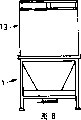
图8是与图4相似的视图,它示出容器-盖组件被转换准备输送到使用地点。Figure 8 is a view similar to Figure 4 showing the container-lid assembly converted for delivery to the point of use.
附图详述Detailed description of the drawings
图1和2示出一个盖1,该盖1包括一个属于第一种形式的容器罩2,该容器罩2用于安装到一个容器的顶部开口上。这种形式的容器罩具有一个接收端3,该接收端3通过一个漏斗形中间部分5与设有一个中央出料装置4的出料端分开。围绕容器罩2有一个框架6。框架6包括支柱7,在该支柱的第一端处有底脚8,而支柱7的另一端被一装配环框架9连接。框架9被加工成一定形状和大小以便在容器的开口端处安置在该容器各侧边的顶部边缘上,并在容器各侧边的顶部边缘附近包围该容器的各侧边。撑条10连接邻近底脚8的支柱7,一对平行的接受器11分别连接一对支柱7。该接受器11被加工成一定形状和尺寸,以便接收一个铲车的叉,因此使盖能很容易地在一个容器的顶部开口上升起和定位或从中取出它们。Figures 1 and 2 show a
标号为12的夹子示意地被示为它们可以是任何合适的类型。夹子12能将框架9夹到容器的顶部上,在容器和框架9之间最好用一个密封垫。Clips, numbered 12, are shown schematically as they may be of any suitable type. Clamps 12 enable the
图3是一种容器罩,它除了漏斗部分5被加工成一定形状以提供一种侧面出料装置4而不是图1的中央定位出料装置外,其总的构型与图1所示的构形相同。最好是该出料装置4包括一个可调节的流量控制装置。Fig. 3 is a kind of container cover, and it except that
在图4中,一个盖1已被夹紧到容器13上,其中容器13包括一个托架底部14,该托架底部14具有4个从该底部14直立的侧边15。该容器可以是这种类型,其中各侧边15可以从底部14上拆下,并且可固定到底部,垂直状态下可锁紧在一起,以便提供一种顶部开口的容器。该容器也可以是这种类型,其中各侧边15被连接到底部14上,使各侧边15能折叠到底部,和从底部升起到所示的直立状态与互锁以形成一个顶部开口的容器。In FIG. 4 , a
在图5中,容器盖组件已被安装到一个倒转器16中,该倒转器16包括一个标号为17的机架支承件,在该机架支承件17上安装一个机架18,以便可绕一标号为19的轴旋转。有一个标号为20的驱动装置,利用该驱动装置20可以将机架18旋转一个预定的弧度,以便倒置一个安放在该机架内的容器-盖组件。In Figure 5, the container lid assembly has been installed in an
如图所示的机架18是一个构架,该构架通常形成一个具有一个开口侧和几个开口端的通道。该通道底(它形成一个机架后侧)标号为21,并且它被设置在开口的机架侧的对面。该通道的彼此间隔开的其余各侧边以标号22标注。机架18的各开口端分别设有封闭件23和24。如图所示,封闭件23和24是与各封闭件一样的铰接门,并且它们都设有适形式的锁定装置,利用该锁定装置可以将封闭件23-24锁定,封盖机架各端部。应该理解,各可拆下的封闭件23-24可被形成为一种替代物,其中封闭件23-24可通过快速连接铰接装置来连接,或者各封闭件25可滑动地安装在机架各端部上。The
在准备一个颠倒程序时,机架18的封闭件24正如通过以26示意表示的适当的锁定装置那样,将被锁定闭合。通过操作驱动装置20,机架18将被定位在图5所示的方位上。在一个优选的方案中,驱动装置将由人工致动,并由各机架位置检测器停止活动,该机架位置检测器与图5和6中所示的两个操作的机架方位相关。In preparation for an inversion procedure, the
容器-盖组件如图所示与搁在封闭件24上的底部14安置在一起,并且该组件靠着机架后部18。为了便于该组件装料,封闭件23将至少部分打开,如图所示。可以用一个合适的装置来保持所需要的封闭件23开度。为该组件装料所需的开度可以改变。所需要的开度可以非常小,它与封闭件24和底部托架14的底之间的一个小间隙相对应,正如由技术熟练的铲车操作人员能够做到的那样。The container-lid assembly is shown seated with the
然后将封闭件23锁定闭合,而当锁定闭合时封闭件23-24之间的间距只是或多或少地大于容器-盖组件的总高度,在机架18倒置时,该组件将基本上避免了端对端的移动。The
然后沿顺时针方向旋转机架18以达到图7的状态。机架的旋转总是这样,在倒置期间使机架后部18支承该组件。The
图7示出下一步操作,该操作是松开上面的封闭件24(以前的下面封闭合件),并按需要打开它,以便能用铲车移开容器-盖组件。图8的倒置的容器-盖组件与一台设备、或料箱或可从出料口4开始出料的别的使用部位成操作关系,可用铲车运输。Figure 7 shows the next step, which is to loosen the upper closure 24 (formerly the lower closure) and open it as required so that the container-lid assembly can be removed with a forklift. The inverted container-lid assembly of Fig. 8 is in operative relationship with a piece of equipment, or a bin or other use where discharge can begin at
应该注意,容器和容器罩之间的连接任何时候都不承受提升应力。为了将罩好的容器装入倒转器(图4)中,提升是通过铲车的叉与容器底部14接合来做到的。从图6将可以看出,通过采用铲车叉的接收器11,不必将任何负荷施加到容器罩和容器之间的联接上,便能从机架上升起并移开容器/容器罩组件。因此,联接只跟容器罩与容器的固定有关。Care should be taken that the connection between the container and the container hood is not subjected to lifting stress at any time. To load the shrouded container into the invertor (FIG. 4), lifting is done by the fork of the forklift engaging the bottom 14 of the container. As will be seen from Figure 6, by using the
上面所述是本发明的一种目前优选的形式。应该理解,在不脱离此处公开的本发明的构思的情况下,可以对所述和所示的结构进行修改。What has been described above is one presently preferred form of the invention. It should be understood that modifications may be made to the structures described and shown without departing from the inventive concept disclosed herein.
Claims (11)
Applications Claiming Priority (2)
| Application Number | Priority Date | Filing Date | Title |
|---|---|---|---|
| AUPN9954 | 1996-05-21 | ||
| AUPN9954A AUPN995496A0 (en) | 1996-05-21 | 1996-05-21 | Method and apparatus for use in discharging containers |
Publications (2)
| Publication Number | Publication Date |
|---|---|
| CN1225068A CN1225068A (en) | 1999-08-04 |
| CN1066117C true CN1066117C (en) | 2001-05-23 |
Family
ID=3794264
Family Applications (1)
| Application Number | Title | Priority Date | Filing Date |
|---|---|---|---|
| CN97196354A Expired - Fee Related CN1066117C (en) | 1996-05-21 | 1997-05-20 | Method and apparatus for converting an open top container into a top discharge container |
Country Status (7)
| Country | Link |
|---|---|
| EP (1) | EP0929489A4 (en) |
| JP (1) | JP2000510801A (en) |
| CN (1) | CN1066117C (en) |
| AU (1) | AUPN995496A0 (en) |
| CA (1) | CA2255733A1 (en) |
| NZ (1) | NZ332839A (en) |
| WO (1) | WO1997044269A1 (en) |
Families Citing this family (5)
| Publication number | Priority date | Publication date | Assignee | Title |
|---|---|---|---|---|
| CA2440693A1 (en) * | 2003-09-10 | 2005-03-10 | Control Automation Pty Ltd | Method and system of unloading contents of a container |
| WO2006116821A1 (en) * | 2005-05-05 | 2006-11-09 | Barry Charles Burrows | Packing aid |
| CN103508215B (en) * | 2012-06-18 | 2016-07-20 | 深圳南方中集物流有限公司 | A kind of rotary apparatus of can container |
| CN105966933B (en) * | 2016-06-29 | 2018-04-17 | 石狮市百祥海产品贸易有限公司 | A kind of loading and unloading structure |
| CN106629003A (en) * | 2016-11-28 | 2017-05-10 | 南京汉安科技实业有限公司 | Rotating disc type discharging device |
Citations (1)
| Publication number | Priority date | Publication date | Assignee | Title |
|---|---|---|---|---|
| JPS59207326A (en) * | 1983-05-06 | 1984-11-24 | Kobe Steel Ltd | Discharging device for matter contained in drum |
Family Cites Families (8)
| Publication number | Priority date | Publication date | Assignee | Title |
|---|---|---|---|---|
| ZA713972B (en) * | 1971-04-19 | 1972-02-23 | Degussa | An apparatus for discharging disposable containers |
| DE3207437C2 (en) * | 1982-02-27 | 1984-04-19 | Simon, Georg, 5810 Witten | Device for emptying containers |
| GB2254595B (en) * | 1991-03-05 | 1994-08-03 | Downs E W & Son Ltd | Box emptying machine |
| GB2256635B (en) * | 1991-04-19 | 1994-09-07 | Downs E W & Son Ltd | Box emptying apparatus |
| NL9101029A (en) * | 1991-06-13 | 1993-01-04 | Zeger Cornelis Houtop | Closure device for an invertable container for bulk materials |
| FR2702331A1 (en) * | 1993-03-11 | 1994-09-16 | Pichenot Jean Louis | Device for handling grains of seed from storage to the seed drill using a method making use of the tilting of the assembly |
| US5344275A (en) * | 1993-03-23 | 1994-09-06 | Helmut Habicht | Method and apparatus for lifting turning and tilting of containers |
| SE504679C2 (en) * | 1994-04-12 | 1997-04-07 | Centramec Ab | Empty arrangement for a container, and method for emptying a container |
-
1996
- 1996-05-21 AU AUPN9954A patent/AUPN995496A0/en not_active Abandoned
-
1997
- 1997-05-20 CN CN97196354A patent/CN1066117C/en not_active Expired - Fee Related
- 1997-05-20 JP JP09541266A patent/JP2000510801A/en active Pending
- 1997-05-20 CA CA002255733A patent/CA2255733A1/en not_active Abandoned
- 1997-05-20 NZ NZ332839A patent/NZ332839A/en unknown
- 1997-05-20 EP EP97921523A patent/EP0929489A4/en not_active Withdrawn
- 1997-05-20 WO PCT/AU1997/000306 patent/WO1997044269A1/en not_active Application Discontinuation
Patent Citations (1)
| Publication number | Priority date | Publication date | Assignee | Title |
|---|---|---|---|---|
| JPS59207326A (en) * | 1983-05-06 | 1984-11-24 | Kobe Steel Ltd | Discharging device for matter contained in drum |
Also Published As
| Publication number | Publication date |
|---|---|
| CN1225068A (en) | 1999-08-04 |
| AUPN995496A0 (en) | 1996-06-13 |
| WO1997044269A1 (en) | 1997-11-27 |
| EP0929489A4 (en) | 2001-05-30 |
| EP0929489A1 (en) | 1999-07-21 |
| CA2255733A1 (en) | 1997-11-27 |
| NZ332839A (en) | 2000-02-28 |
| JP2000510801A (en) | 2000-08-22 |
Similar Documents
| Publication | Publication Date | Title |
|---|---|---|
| US20080142549A1 (en) | Apparatus for the discharge of product from a bulk bag | |
| JPH11513004A (en) | Container discharging means | |
| US4744183A (en) | Lid opener | |
| AU2008200210A1 (en) | Flexible container discharge apparatus and method | |
| CN1066117C (en) | Method and apparatus for converting an open top container into a top discharge container | |
| JPH01500347A (en) | Method and apparatus for filling containers under vacuum | |
| US6227408B1 (en) | Method and apparatus for discharging bags | |
| FR2693981A1 (en) | Equipment for emptying bags containing a fluid product. | |
| US4449886A (en) | Apparatus for fining bottled wine | |
| GB2203719A (en) | Tipping containers | |
| US4343586A (en) | Dumping apparatus and method | |
| US6186726B1 (en) | Method and apparatus to convert an open topped container into a top discharging container | |
| NL1009406C2 (en) | Device and method for emptying a container with contents, such as fruits. | |
| US7118319B1 (en) | Bulk closure dispensing system | |
| AU726132B2 (en) | Method and apparatus to convert an open topped container into a top discharging container | |
| US20050194405A1 (en) | Bulk bag handling apparatus and method | |
| AU2003246237A1 (en) | Method and System of Unloading Contents of a Container | |
| US6848878B2 (en) | Two stage dumper apparatus and method | |
| GB2137159A (en) | Emptying a Flexible Lining of a Container | |
| US20050194406A1 (en) | Apparatus for the discharge of bulk bags | |
| SU1425153A1 (en) | Container emptying apparatus | |
| CN217004023U (en) | Laboratory liquid nitrogen pouring device | |
| MXPA98002567A (en) | Container discharge means | |
| AU6324800A (en) | Apparatus for emptying receptacle | |
| CN214730312U (en) | Wet material drying and packaging integrated machine |
Legal Events
| Date | Code | Title | Description |
|---|---|---|---|
| C06 | Publication | ||
| PB01 | Publication | ||
| C10 | Entry into substantive examination | ||
| SE01 | Entry into force of request for substantive examination | ||
| C14 | Grant of patent or utility model | ||
| GR01 | Patent grant | ||
| C19 | Lapse of patent right due to non-payment of the annual fee | ||
| CF01 | Termination of patent right due to non-payment of annual fee |