CN106525772B - High-precision ultra-low range on-line turbidity sensor and turbidity measurement method thereof - Google Patents
High-precision ultra-low range on-line turbidity sensor and turbidity measurement method thereof Download PDFInfo
- Publication number
- CN106525772B CN106525772B CN201611182201.3A CN201611182201A CN106525772B CN 106525772 B CN106525772 B CN 106525772B CN 201611182201 A CN201611182201 A CN 201611182201A CN 106525772 B CN106525772 B CN 106525772B
- Authority
- CN
- China
- Prior art keywords
- light
- light source
- singlechip
- phase
- pulse
- Prior art date
- Legal status (The legal status is an assumption and is not a legal conclusion. Google has not performed a legal analysis and makes no representation as to the accuracy of the status listed.)
- Active
Links
- 238000000691 measurement method Methods 0.000 title claims description 6
- 230000003287 optical effect Effects 0.000 claims abstract description 21
- 238000006243 chemical reaction Methods 0.000 claims abstract description 10
- 238000004140 cleaning Methods 0.000 claims abstract description 9
- XLYOFNOQVPJJNP-UHFFFAOYSA-N water Substances O XLYOFNOQVPJJNP-UHFFFAOYSA-N 0.000 claims description 84
- 238000000034 method Methods 0.000 claims description 21
- 239000011521 glass Substances 0.000 claims description 12
- 238000003491 array Methods 0.000 claims description 9
- 238000004891 communication Methods 0.000 claims description 8
- 239000005357 flat glass Substances 0.000 claims description 7
- 239000000463 material Substances 0.000 claims description 7
- 239000004677 Nylon Substances 0.000 claims description 5
- 229920001778 nylon Polymers 0.000 claims description 5
- 239000000284 extract Substances 0.000 claims description 4
- 238000012805 post-processing Methods 0.000 claims description 3
- 238000012545 processing Methods 0.000 claims description 3
- 229910052594 sapphire Inorganic materials 0.000 claims description 3
- 239000010980 sapphire Substances 0.000 claims description 3
- 238000005259 measurement Methods 0.000 abstract description 13
- 239000003344 environmental pollutant Substances 0.000 abstract description 3
- 231100000719 pollutant Toxicity 0.000 abstract description 3
- 238000007599 discharging Methods 0.000 abstract description 2
- TWNQGVIAIRXVLR-UHFFFAOYSA-N oxo(oxoalumanyloxy)alumane Chemical group O=[Al]O[Al]=O TWNQGVIAIRXVLR-UHFFFAOYSA-N 0.000 description 6
- 230000005540 biological transmission Effects 0.000 description 5
- 238000010586 diagram Methods 0.000 description 5
- 230000000694 effects Effects 0.000 description 5
- 238000002474 experimental method Methods 0.000 description 5
- 239000002245 particle Substances 0.000 description 5
- 239000012086 standard solution Substances 0.000 description 4
- 238000010998 test method Methods 0.000 description 3
- 238000010521 absorption reaction Methods 0.000 description 2
- 230000009286 beneficial effect Effects 0.000 description 2
- 238000007872 degassing Methods 0.000 description 2
- 229910003460 diamond Inorganic materials 0.000 description 2
- 239000010432 diamond Substances 0.000 description 2
- 230000007774 longterm Effects 0.000 description 2
- 238000005070 sampling Methods 0.000 description 2
- 238000000790 scattering method Methods 0.000 description 2
- 239000000243 solution Substances 0.000 description 2
- 239000000758 substrate Substances 0.000 description 2
- 239000003990 capacitor Substances 0.000 description 1
- 239000000084 colloidal system Substances 0.000 description 1
- 238000007865 diluting Methods 0.000 description 1
- 239000006185 dispersion Substances 0.000 description 1
- 230000002349 favourable effect Effects 0.000 description 1
- 238000005374 membrane filtration Methods 0.000 description 1
- 238000012986 modification Methods 0.000 description 1
- 230000004048 modification Effects 0.000 description 1
- 238000012544 monitoring process Methods 0.000 description 1
- 239000002689 soil Substances 0.000 description 1
- 239000008399 tap water Substances 0.000 description 1
- 235000020679 tap water Nutrition 0.000 description 1
Images


Classifications
-
- G—PHYSICS
- G01—MEASURING; TESTING
- G01N—INVESTIGATING OR ANALYSING MATERIALS BY DETERMINING THEIR CHEMICAL OR PHYSICAL PROPERTIES
- G01N21/00—Investigating or analysing materials by the use of optical means, i.e. using sub-millimetre waves, infrared, visible or ultraviolet light
- G01N21/17—Systems in which incident light is modified in accordance with the properties of the material investigated
- G01N21/47—Scattering, i.e. diffuse reflection
- G01N21/49—Scattering, i.e. diffuse reflection within a body or fluid
- G01N21/51—Scattering, i.e. diffuse reflection within a body or fluid inside a container, e.g. in an ampoule
-
- Y—GENERAL TAGGING OF NEW TECHNOLOGICAL DEVELOPMENTS; GENERAL TAGGING OF CROSS-SECTIONAL TECHNOLOGIES SPANNING OVER SEVERAL SECTIONS OF THE IPC; TECHNICAL SUBJECTS COVERED BY FORMER USPC CROSS-REFERENCE ART COLLECTIONS [XRACs] AND DIGESTS
- Y02—TECHNOLOGIES OR APPLICATIONS FOR MITIGATION OR ADAPTATION AGAINST CLIMATE CHANGE
- Y02A—TECHNOLOGIES FOR ADAPTATION TO CLIMATE CHANGE
- Y02A20/00—Water conservation; Efficient water supply; Efficient water use
- Y02A20/20—Controlling water pollution; Waste water treatment
Landscapes
- Physics & Mathematics (AREA)
- Health & Medical Sciences (AREA)
- Life Sciences & Earth Sciences (AREA)
- Chemical & Material Sciences (AREA)
- Analytical Chemistry (AREA)
- Biochemistry (AREA)
- General Health & Medical Sciences (AREA)
- General Physics & Mathematics (AREA)
- Immunology (AREA)
- Pathology (AREA)
- Investigating Or Analysing Materials By Optical Means (AREA)
Abstract
The invention discloses a high-precision ultra-low range on-line turbidity sensor, which comprises a measuring pool, a deaeration bubble device, a light source chamber, an evacuating device and a circuit chamber, wherein the deaeration bubble device, the light source chamber, the evacuating device and the circuit chamber are connected with the measuring pool, and the light source chamber comprises: the LED light source, the LED light cavity, the collimating filter and the light outlet diaphragm; the bubble removal device comprises: round holes, pipelines and overflow tanks; one side of the measuring pool is provided with an electric cleaning brush, an optical window and a receiving cavity; the evacuation device comprises: an evacuation lumen and an evacuation tube connector; the circuit chamber includes: the device comprises a photodiode, an IV conversion electric appliance, a phase-locked amplifier, a secondary voltage amplifier, an ADC (analog to digital converter), a singlechip and a light source driving and discharging switch. The invention has the advantages of extracting very weak light signals, eliminating the influence of bubbles, pollutants and stray light on turbidity measurement results, and the like.
Description
Technical Field
The invention relates to the technical field of water treatment, in particular to a high-precision ultra-low range on-line turbidity sensor and a turbidity measuring method thereof.
Background
The water contains suspended matters and colloid matters such as soil, silt, fine organic matters, inorganic matters, plankton and the like, and can cause the water to become turbid to form a certain turbidity, and generally the higher the turbidity is, the more turbid the solution is. The commonly used turbidity measuring method is a transmission method and a scattering method, wherein a measuring device emits light to pass through a section of sample, and detects how much light is scattered by particles in water from a direction which is 90 degrees to the incident light, and the scattered light measuring method is called a scattering method; a method of measuring turbidity by measuring the degree of attenuation of light intensity after light passes through a sample is called a transmission method. However, scattering is a well-accepted practice due to interference effects such as color absorption or particulate absorption in the transmission method.
The following problems mainly exist in the prior art: 1. in ultra-low turbidity water, such as tap water, membrane filtration water, the light intensity scattering ability of these water bodies is extremely weak, and the water bodies are basically submerged in the noise of the circuit; 2. in outdoor water areas, the measured signals can be interfered by sunlight, so that measurement is inaccurate; 3. in the online measurement process, the water sample is in a circulation state, and water from the sampling tube flows into a water pool of the sensor, so that a large number of tiny bubbles are generated in the water sample due to the change of water pressure, and turbidity measurement results are influenced; 4. in the online measurement process, a water sample flows into a water tank of the sensor and flows out in an overflow mode, if the water in the water tank is not completely emptied for a long time, large particles possibly remain in the water tank, so that the large particles are accumulated, and the measurement result is influenced; 5. because the sampling end of the on-line sensor is submerged in water for a long time, pollutants are easily accumulated on the optical window sheet, and light scattered to the window can be absorbed, so that the measurement effect is affected; 6. if the online turbidity sensor is placed outdoors for a long time, the sensor has zero drift due to large outdoor temperature difference, so that the reading is inaccurate; 7. because the light of the LED still can not guarantee that the light is completely parallel after being collimated by the lens, stray light can directly enter the photoelectric acquisition module to influence the measurement effect, if the stray light is too strong, turbidity scattered light can be too low during low turbidity monitoring, and as the frequency of the stray light is the same as that of a scattered light signal, a normal turbidity signal is submerged in the stray light signal, so that turbidity can not be detected.
Therefore, in the technical field of water treatment, there is a strong need for a high-precision ultra-low range on-line turbidity sensor and a turbidity measurement method thereof, which can extract very weak light signals and eliminate the influence of bubbles, pollutants and stray light on turbidity measurement results.
Disclosure of Invention
In order to achieve the above purpose, the specific technical scheme of the high-precision ultra-low range on-line turbidity sensor is as follows:
a high-precision ultra-low range on-line turbidity sensor comprises a measuring pool, a deaeration bubble device, a light source chamber, an evacuating device and a circuit chamber, wherein the deaeration bubble device, the light source chamber, the evacuating device and the circuit chamber are connected with the measuring pool.
Further, the light source chamber includes: the LED light source, the LED light cavity, the collimating filter and the light-emitting diaphragm.
Furthermore, small steps are distributed in the light-emitting diaphragm, and the small steps are used for eliminating light beams with divergence angles larger than the inclination angles in the light-emitting diaphragm.
Further, the bubble removal device includes: the circular hole array is a cylindrical hole array with 2 rows and 7 columns, the communicating pipe sequentially penetrates through the bottoms of the circular hole arrays to enable the circular hole arrays to be connected together, a water inlet is formed in a first cylindrical hole in the circular hole array, a water outlet is formed in a last cylindrical hole of the circular hole array, water enters a measuring pond through the water outlet, the bottoms of the circular hole arrays are mutually connected, and in the process that the water sequentially flows through the communicating pipe, bubbles can float upwards to the upper portion of the circular hole to remove the bubbles due to the fact that the water pressure of the communicating pipe is larger than that of the circular hole array.
Further, an electric cleaning brush, an optical window and a receiving cavity are arranged on one side of the measuring water tank, the rear end of the receiving cavity is connected with the circuit chamber, an overflow notch is arranged on the other side of the measuring water tank, and water in the measuring water tank overflows into the overflow groove through the overflow notch; the inside of measuring the pond and the light-emitting diaphragm is all made with full black nylon materials, the bottom of measuring the pond is V type, and the water evacuation in the measuring pond is more favorable to the V type structure.
Further, the evacuation device includes: the device comprises an exhaust cavity and an exhaust pipe joint, wherein an electromagnetic valve is arranged on the exhaust joint.
Further, the circuit chamber includes: the LED light source comprises a photodiode, an IV conversion electric appliance, a phase-locked amplifier, a secondary voltage amplifier, an ADC converter, a singlechip, a light source driver and a discharge switch, wherein the input end of the IV conversion electric appliance is connected with the photodiode, the output end of the IV conversion electric appliance is connected with the input end of the phase-locked amplifier, the pulse signal input end of the phase-locked amplifier is also connected with the output end of the singlechip and used for receiving a pulse signal generated by the singlechip, the output end of the phase-locked amplifier is connected with the input end of the secondary voltage amplifier, the output end of the phase-locked amplifier is also connected with the discharge switch, the output end of the secondary voltage amplifier is connected with the input end of the ADC converter, the output end of the ADC converter is connected with the input end of the singlechip, the output end of the singlechip is connected with the light source driver, the output end of the singlechip is also connected with the discharge switch, and the light source driver is connected with the LED light source.
Further, the window glass of the optical window is sapphire (Al 2O 3); the high-precision ultra-low range on-line turbidity sensor also comprises a water inlet pipe and an overflow pipe.
The high-precision ultra-low range on-line turbidity measurement method comprises the following steps:
firstly, a water body to be tested enters the deaeration device through the water inlet pipe to be deaerated;
step two, the singlechip transmits pulse signals to the light source driver and the phase-locked amplifier, the light source driver generates pulse light through an LED light source, and the phase-locked amplifier receives the pulse signals from the singlechip;
the angle range of the emergent light is adjusted by changing the diameter of the emergent light diaphragm, the distance from the bottom of the optical cavity to the emergent light diaphragm and the distance from the glass window to the center of the emergent light; minimizing stray light;
small steps are distributed in the light-emitting diaphragm, and light beams with divergence angles larger than the internal inclination angle of the light-emitting diaphragm in incident light are eliminated;
step three, scattered light generated after the incident light is scattered by the water body to be detected is injected into the circuit chamber;
and step four, receiving scattered light from the measuring pool by using the photodiode in the circuit chamber, and obtaining the turbidity value of the water body to be measured after treatment.
The specific method for the fourth step is as follows:
scattered light irradiates the photodiode, the photodiode generates a pulse current signal, the pulse current signal is transmitted to an IV converter, the IV converter converts the pulse current signal into a pulse voltage signal, and the pulse voltage signal is transmitted to the lock-in amplifier; the phase-locked amplifier performs phase-locking processing on the received pulse voltage signal and the pulse signal from the singlechip, and only extracts signals with the same frequency and phase as those of the pulse signal of the singlechip; the extracted pulse signals are amplified by a secondary voltage amplifier and then transmitted to an ADC converter, and analog signals are converted into digital signals and transmitted to the singlechip; the single chip microcomputer reads the digital quantity of the ADC converter and obtains turbidity value through post-processing.
The beneficial effects of the invention are as follows:
1. in the deaeration bubble device, the bottoms of the circular hole arrays are connected with each other, and in the process that water sequentially flows through the communication pipelines, bubbles can float to the upper parts of the circular holes due to the fact that the water pressure of the communication pipelines is larger than that of the circular hole arrays, so that the bubbles are removed.
2. The light source chamber is internally provided with the light-emitting diaphragm, and small steps are distributed in the light-emitting diaphragm, so that light beams with divergence angles larger than the internal inclination angle of the light-emitting diaphragm in incident light beams can be effectively eliminated.
3. The inside of the measuring pool and the light-emitting diaphragm are made of all-black nylon materials, so that incident light can be absorbed to the maximum extent, multiple reflections of the light are reduced, and stray light is generated.
4. The bottom of the measuring pond is V-shaped, so that water can be completely emptied when the measuring pond is emptied, and large particles can be completely discharged out of the measuring pond.
5. The bottom of the measuring pool is provided with the emptying pipe joint and the electric water valve, so that the measuring pool can be automatically emptied, one side of the measuring pool is provided with the automatic cleaning brush, and the measuring pool is periodically rotated for a certain number of turns to clean dirt of an optical window.
6. The glass of the optical window is made of sapphire (Al 2O 3), the sapphire (Al 2O 3) is an infrared optical window/substrate material with excellent performance, the transmission range is 0.2-5.5um, the glass is high-temperature resistant and high in hardness, and the glass is inferior to diamond, and the sapphire window glass is used, so that the automatic cleaning brush can not abrade the window glass in long-term work.
7. The phase-locked amplifier is arranged in the circuit chamber, so that signals with the same frequency as the reference signals of the phase-locked amplifier can be extracted, and interference of other signals with different wave bands, such as interference of thermal noise, ambient light and photoelectric dark current, can be eliminated.
8. The zero point calibration method of pure software is adopted, a temperature sensor is not required to be introduced, the calculation is convenient, and the implementation is simple.
Drawings
The invention is described in detail below with reference to the attached drawing figures and the detailed description:
FIG. 1 is a schematic diagram of an on-line turbidity sensor with high accuracy and ultra-low range according to the present invention.
Fig. 2 is a schematic diagram of the circuit chamber of fig. 1.
Fig. 3 is a schematic diagram of the positions of the light-emitting diaphragm and the light-receiving cavity.
Fig. 4 is a top view of the bubble removal apparatus.
Fig. 5 is a side view of the bubble removal apparatus.
Detailed Description
In order to better understand the purpose, structure and function of the present invention, a high-precision low-range on-line turbidity sensor according to the present invention is described in further detail below with reference to the accompanying drawings.
FIG. 1 is a schematic diagram of an on-line turbidity sensor with high accuracy and ultra-low range according to the present invention.
As shown in figure 1, the high-precision ultra-low range on-line turbidity sensor comprises a measuring water tank 1, a degassing bubble device 2, a light source chamber 3, an evacuating device 4 and a circuit chamber 5, wherein the degassing bubble device 2, the light source chamber 3, the evacuating device 4 and the circuit chamber 5 are connected with the measuring water tank.
Preferably, the light source chamber 3 in the present embodiment includes: an LED light source 35, an LED light cavity 31, a collimating filter 32 and an exit aperture 34.
Preferably, the light exit aperture 34 in this embodiment has small steps distributed therein for eliminating the light beam having a divergence angle larger than the inclination angle of the light exit aperture 34.
Preferably, the bubble removal device 2 in the present embodiment includes: the circular hole array 21 is a cylindrical hole array of 2 rows and 8 columns, the communicating pipe 22 sequentially penetrates through the bottom of the circular hole array 21 so as to connect the circular hole arrays 21 together, the first cylindrical hole in the circular hole array 21 is provided with a water inlet, the last cylindrical hole in the circular hole array 21 is provided with a water outlet, and water enters the measuring pool 1 through the water outlet.
Preferably, one side of the measuring reservoir 1 in the present embodiment is provided with an electric cleaning brush 11, an optical window 12 and a receiving cavity 13, and the rear end of the receiving cavity 13 is connected with the circuit chamber 5, and the other side is provided with an overflow notch 11, through which overflow notch 11 the water in the measuring reservoir 1 overflows into an overflow trough 23.
Preferably, the measuring pool 1 and the light-emitting diaphragm 33 in the present embodiment are made of all black nylon materials, so that incident light can be absorbed to the maximum extent, multiple reflections of the light are reduced, stray light is generated, the bottom of the measuring pool 1 is V-shaped, and the V-shaped structure is more beneficial to draining water in the measuring pool.
Preferably, the evacuation device 4 in this embodiment includes: the exhaust cavity 41 and the exhaust pipe joint 42 are provided with an electromagnetic valve 43, the electromagnetic valve 43 is connected with a singlechip 55, and the singlechip 55 controls the switch of the electromagnetic valve 42; for example, the opening time of the electromagnetic valve is set to be T1, the closing time is set to be T2, the working period is set to be T0, the singlechip monitors whether the time of the internal timer exceeds T0, and if the time exceeds the time, the next step is continued; opening the electromagnetic valve, wherein the opening time is T1, and the water tank is measured to start to drain within the T1 time, and the next step is continued after the T1 time is up; closing the electromagnetic valve, and after delaying for T2 time, starting signal acquisition, and in the T2 time, storing water in the measuring water tank, wherein the setting of the T2 time is to enable the measuring water tank to be full of water in the T2 time.
Preferably, the window glass of the optical window 12 in this embodiment is sapphire (Al 2O 3).
Preferably, the high-precision ultra-low range on-line turbidity sensor further comprises a water inlet pipe 6 and an overflow pipe 7, wherein the water in the overflow groove 23 is discharged through the overflow pipe 7.
Fig. 2 is a schematic diagram of the circuit chamber of fig. 1.
As shown in fig. 2, the circuit chamber 5 in the present embodiment includes: the LED light source comprises a photodiode 51, an IV conversion electric appliance 52, a phase-locked amplifier 53, a secondary voltage amplifier 57, an ADC converter 56, a single-chip microcomputer 55, a light source driver 54 and a discharge switch 58, wherein the input end of the IV conversion electric appliance 52 is connected with the photodiode 51, the output end of the IV conversion electric appliance 52 is connected with the input end of the phase-locked amplifier 53, the pulse signal input end of the phase-locked amplifier 53 is also connected with the output end of the single-chip microcomputer 55 and is used for receiving a pulse signal generated by the single-chip microcomputer 55, the output end of the phase-locked amplifier 53 is connected with the input end of the secondary voltage amplifier 57, the output end of the phase-locked amplifier 53 is also connected with the discharge switch 58, the output end of the secondary voltage amplifier 57 is connected with the input end of the ADC converter 56, the output end of the ADC converter 56 is connected with the input end of the single-chip microcomputer 55, the output end of the single-chip microcomputer 55 is connected with the light source driver 54, and the output end of the single-chip microcomputer 55 is also connected with the switch 58, and the output end of the single-chip microcomputer 55 is connected with the light source driver 35.
The turbidity measuring method of the invention comprises the following steps:
firstly, a water body to be tested enters a deaeration device 2 through a water inlet pipe 6 to be deaerated;
the water body to be measured enters the deaeration device 2 through the water inlet pipe 6; as shown in fig. 4 and 5, the water to be measured sequentially flows through the communication pipeline 22, and in the water flow process, as the water pressure of the communication pipeline 22 is greater than the water pressure of the circular hole array 21, bubbles in the water to be measured naturally float to the upper part of the circular hole array 21, so that the effect of discharging the bubbles is achieved; the water body to be measured passes through the bubble removing device 2 and enters the measuring water tank 1;
step two, the singlechip 55 transmits pulse signals to the light source driver 54 and the lock-in amplifier 53, the light source driver 54 generates pulse light through the LED light source 35, and the lock-in amplifier 53 receives the pulse signals from the singlechip 55;
firstly, a singlechip 55 is turned on to switch, the singlechip 55 transmits a pulse signal to a light source driver 54, and the light source driver 54 transmits pulse light through an LED light source 35; the LED light source 35 in the light source chamber 3 emits a light source of 860 nm; the light source sequentially passes through the LED optical cavity 31, the collimating lens 32 and the light-emitting diaphragm 33 and then becomes incident light controlled within a certain angle range, and the proper angle range of the incident light can be obtained by adjusting the diameter A of the light-emitting diaphragm in the light hole, the distance L from the bottom of the optical cavity to the light-emitting diaphragm in the light-entering opening and the distance M from the glass window to the center of emitted light, so that the stray light is smaller than 20.5 degrees. The method comprises the following steps:
as shown in fig. 3, the light-emitting angle through the light-emitting diaphragm is C, where a represents the diameter of the light-entering aperture of the light-emitting diaphragm, L represents the distance from the bottom of the receiving light cavity to the light-entering aperture of the light-emitting diaphragm, M represents the distance from the glass window to the center of the emitted light, and N represents the radius of the dispersion of the section of the emitted light.
Setting N < M can prevent the scattered light from falling into the glass window, and the stray light is minimum at this time;
from mathematical knowledge it follows that:
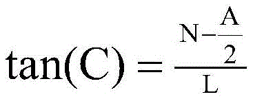
so that: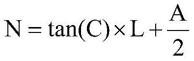
because of the fact that N < M,
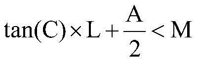
finally, the light-emitting angle C is obtained:
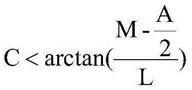
in the present invention, l=40m=20a=10 can be selected, resulting in C <20.5 °.
As an example, it should be understood by those skilled in the art that after the incident light passes through the light-emitting aperture 33, the angle can be controlled within 20.5 °, and the angle range of the incident light can be adjusted by changing the diameter a of the light-emitting aperture, the distance L from the bottom of the light cavity to the light-emitting aperture, and the distance M from the glass window to the center of the emitted light, as required; minimizing stray light.
The light beam having a divergence angle larger than the internal inclination angle of the light exit diaphragm 33 in the incident light can be effectively eliminated by distributing small steps inside the light exit diaphragm 33.
Step three, scattered light generated after the incident light is scattered by the water body to be detected is injected into the circuit chamber 5;
the incident light processed by the light-emitting diaphragm 33 in the second step is injected into the water body to be measured in the measuring pool 1; the scattered light scattered by the water body to be measured sequentially passes through the optical window 12 and the receiving cavity 13 and enters the circuit chamber 5.
An electric cleaning brush is arranged in front of the optical window 12, and can be rotated for a certain number of times to clean dirt on the optical window 12.
And step four, the photodiode 51 in the circuit chamber 5 receives scattered light from the measuring pool 1, and the turbidity value of the water body to be measured is obtained after the circuit chamber 5 is processed. The method comprises the following steps:
scattered light is irradiated onto the photodiode 51, the photodiode 51 generates a pulse current signal, the pulse current signal is transmitted to the IV converter 52, and the IV converter 52 converts the pulse current signal into a pulse voltage signal and then transmits the pulse voltage signal to the lock-in amplifier 53; the phase-locked amplifier 53 performs phase-locking processing on the received pulse voltage signal and the pulse signal from the singlechip 55, and only extracts signals with the same frequency and phase as those of the pulse signal of the singlechip 55, thereby eliminating interference and improving the measurement precision and accuracy; the extracted pulse signal is amplified by a secondary voltage amplifier 57 and then transmitted to an ADC (analog-to-digital converter) 56, and the analog signal is converted into a digital signal and transmitted to a singlechip 55; the singlechip 55 reads the digital quantity of the ADC converter 56 and obtains the turbidity value through post-processing.
To further illustrate the effects of the present invention, a zero drift experiment and an indication error experiment may be performed.
The invention adopts a part calibration method of pure software when zero calibration is carried out, and the specific steps are as follows: the LED light source 31 is turned off, the discharge switch 58 is turned on, the charge on the filter capacitor at the output end of the lock-in amplifier 53 is discharged for executing zero calibration, the numerical value of the ADC converter 56 at the moment is read, a certain number of times is read, and the average value is calculated as zero. The specific experiment is as follows:
in the lowest range of the invention, the zero point T is adjusted by zero turbidity 0 Experiments were performed in a high-low temperature cabinet, and data T was recorded every 10℃C i The zero drift deltat is calculated as follows i Taking the delta T with the maximum absolute value i Is zero drift:
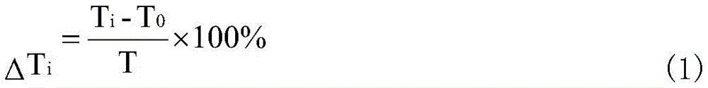
experimental data
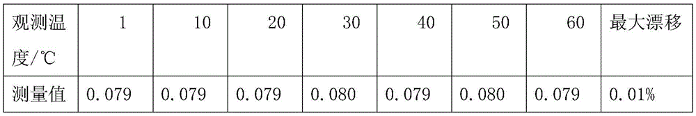
Zero drift of 0.01% of the zero drift range of the instrument JJJG 880-2006 of the turbidimeter calibration protocol is calculated by the formula 1 to be +/-1.5%.
Indication error experiment:
selecting the same bottle of standard solution, uniformly selecting five measuring points in a range, and accurately diluting and preparing a standard solution T of a corresponding turbidity solution s . Each concentration was measured 3 times to obtain a measurement value T m Average value thereof And (3) respectively calculating the indication relative errors under the five concentrations according to a formula (2), and taking a measurement result in which the maximum error represents the indication error.

T s Nominal value of configured standard solution

Experimental data:
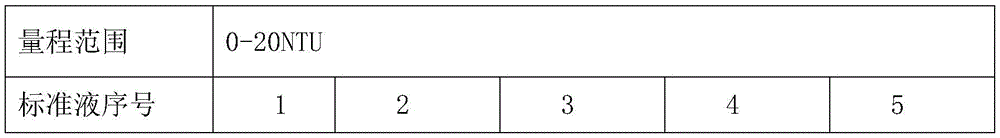

the error of the display value is calculated to be 2.49% according to the formula 2, the error of the display value of a turbidimeter test procedure JJG 880-2006 instrument is not more than +/-10%, and the error of the display value measured by the turbidimeter test procedure is obviously smaller than the error range specified in the turbidimeter test procedure.
From the above, in the deaeration bubble device of the present invention, the bottoms of the circular hole arrays are connected with each other, and in the process of water flowing through the communication pipes in turn, the bubbles float to the upper parts of the circular holes due to the fact that the water pressure of the communication pipes is larger than that of the circular hole arrays, so that the bubbles are removed. The light source chamber is internally provided with the light-emitting diaphragm, small steps are distributed in the light-emitting diaphragm, and light beams with divergence angles larger than the internal inclination angles of the light-emitting diaphragm in the incident light beams can be effectively eliminated. The inside of the measuring pool and the light outlet diaphragm are made of all black nylon materials, so that incident light can be absorbed to the maximum extent, multiple reflections of the light are reduced, and stray light is generated. The bottom of the measuring pond is V-shaped, so that when the measuring pond is emptied, water can be completely emptied, and large particles can be completely discharged out of the measuring pond. The bottom of the measuring pond is provided with an emptying pipe joint and an electric water valve, so that the measuring pond can be automatically emptied, one side of the measuring pond is provided with an automatic cleaning brush, and the measuring pond is periodically rotated for a certain number of turns to clean dirt of an optical window. The glass of the optical window is made of sapphire (Al 2O 3), the sapphire (Al 2O 3) is an infrared optical window/substrate material with excellent performance, the transmission range is 0.2-5.5um, the glass is high-temperature resistant and high in hardness, and the glass is inferior to diamond, and the sapphire window glass is selected, so that the automatic cleaning brush can not abrade the window glass in long-term work. The phase-locked amplifier is arranged in the circuit chamber, so that signals with the same frequency as the reference signals of the phase-locked amplifier can be extracted, and interference of signals with different wave bands, such as interference of thermal noise, ambient light and photoelectric dark current, is eliminated.
The zero point calibration method of pure software is adopted, a temperature sensor is not required to be introduced, the calculation is convenient, and the implementation is simple.
The foregoing has shown and described the basic principles, principal features and advantages of the invention. It will be understood by those skilled in the art that the present invention is not limited to the embodiments described above, and that the above embodiments and descriptions are merely illustrative of the principles of the present invention, and various changes and modifications may be made without departing from the spirit and scope of the invention, which is defined in the appended claims. The scope of the invention is defined by the appended claims and equivalents thereof.
Claims (7)
1. The high-precision ultra-low range on-line turbidity sensor is characterized by comprising a measuring pond, a deaeration bubble device, a light source chamber, an evacuating device and a circuit chamber, wherein the deaeration bubble device, the light source chamber, the evacuating device and the circuit chamber are connected with the measuring pond;
the light source chamber includes: the LED light source, the LED light cavity, the collimating filter and the light-emitting diaphragm, wherein the LED light source is connected with the circuit chamber;
the bubble removal device includes: the device comprises a round hole array, a communication pipeline and an overflow groove, wherein the round hole array is a cylindrical hole array of 2 rows and 7 columns, the communication pipeline sequentially penetrates through the bottom of the round hole array so as to connect the round hole arrays together, a first cylindrical hole in the round hole array is provided with a water inlet, a last cylindrical hole of the round hole array is provided with a water outlet, and water enters a measuring pool through the water outlet;
the evacuation device includes: the device comprises an exhaust cavity and an exhaust pipe joint, wherein an electromagnetic valve is arranged on the exhaust pipe joint;
the circuit chamber includes: the LED light source comprises a photodiode, an IV conversion electric appliance, a phase-locked amplifier, a secondary voltage amplifier, an ADC converter, a singlechip, a light source driver and a discharge switch, wherein the input end of the IV conversion electric appliance is connected with the photodiode, the output end of the IV conversion electric appliance is connected with the input end of the phase-locked amplifier, the pulse signal input end of the phase-locked amplifier is also connected with the output end of the singlechip and used for receiving a pulse signal generated by the singlechip, the output end of the phase-locked amplifier is connected with the input end of the secondary voltage amplifier, the output end of the phase-locked amplifier is also connected with the discharge switch, the output end of the secondary voltage amplifier is also connected with the input end of the ADC converter, the output end of the ADC converter is connected with the input end of the singlechip, the output end of the singlechip is connected with the light source driver, and the output end of the singlechip is also connected with the discharge switch.
2. The high-precision ultra-low range on-line turbidity sensor according to claim 1, wherein small steps are distributed in the light-emitting diaphragm for eliminating light beams with divergence angles larger than the inclination angles in the light-emitting diaphragm.
3. The high-precision ultra-low range on-line turbidity sensor according to claim 1, wherein one side of the measuring pool is provided with an electric cleaning brush, an optical window and a receiving cavity, the rear end of the receiving cavity is connected with a circuit chamber, and the other side of the measuring pool is provided with an overflow notch.
4. The high-precision ultra-low range on-line turbidity sensor according to claim 1, wherein the inside of the measuring pool and the light-emitting diaphragm are both made of all-black nylon materials, and the bottom of the measuring pool is V-shaped.
5. The high-precision ultra-low range on-line turbidity sensor of claim 3, further comprising a water inlet pipe and an overflow pipe; the window glass of the optical window is sapphire.
6. A high-precision ultra-low range on-line turbidity measurement method using the high-precision ultra-low range on-line turbidity sensor according to claim 5, comprising the steps of:
firstly, a water body to be tested enters the deaeration device through the water inlet pipe to be deaerated;
step two, the singlechip transmits pulse signals to the light source driver and the phase-locked amplifier, the light source driver generates pulse light through an LED light source, and the phase-locked amplifier receives the pulse signals from the singlechip;
the angle range of the emergent light is adjusted by changing the diameter of the emergent light diaphragm, the distance from the bottom of the optical cavity to the emergent light diaphragm and the distance from the glass window to the center of the emergent light; minimizing stray light;
small steps are distributed in the light-emitting diaphragm, and light beams with divergence angles larger than the internal inclination angle of the light-emitting diaphragm in incident light are eliminated;
step three, scattered light generated after the incident light is scattered by the water body to be detected is injected into the circuit chamber;
and step four, receiving scattered light from the measuring pool by using the photodiode in the circuit chamber, and obtaining the turbidity value of the water body to be measured after treatment.
7. The high-precision ultra-low range on-line turbidity measurement method according to claim 6, wherein the specific method in the fourth step is as follows:
scattered light irradiates the photodiode, the photodiode generates a pulse current signal, the pulse current signal is transmitted to an IV converter, the IV converter converts the pulse current signal into a pulse voltage signal, and the pulse voltage signal is transmitted to the lock-in amplifier; the phase-locked amplifier performs phase-locking processing on the received pulse voltage signal and the pulse signal from the singlechip, and only extracts signals with the same frequency and phase as those of the pulse signal of the singlechip; the extracted pulse signals are amplified by a secondary voltage amplifier and then transmitted to an ADC converter, and analog signals are converted into digital signals and transmitted to the singlechip; the single chip microcomputer reads the digital quantity of the ADC converter and obtains turbidity value through post-processing.
Priority Applications (1)
| Application Number | Priority Date | Filing Date | Title |
|---|---|---|---|
| CN201611182201.3A CN106525772B (en) | 2016-12-20 | 2016-12-20 | High-precision ultra-low range on-line turbidity sensor and turbidity measurement method thereof |
Applications Claiming Priority (1)
| Application Number | Priority Date | Filing Date | Title |
|---|---|---|---|
| CN201611182201.3A CN106525772B (en) | 2016-12-20 | 2016-12-20 | High-precision ultra-low range on-line turbidity sensor and turbidity measurement method thereof |
Publications (2)
| Publication Number | Publication Date |
|---|---|
| CN106525772A CN106525772A (en) | 2017-03-22 |
| CN106525772B true CN106525772B (en) | 2023-06-09 |
Family
ID=58341124
Family Applications (1)
| Application Number | Title | Priority Date | Filing Date |
|---|---|---|---|
| CN201611182201.3A Active CN106525772B (en) | 2016-12-20 | 2016-12-20 | High-precision ultra-low range on-line turbidity sensor and turbidity measurement method thereof |
Country Status (1)
| Country | Link |
|---|---|
| CN (1) | CN106525772B (en) |
Families Citing this family (6)
| Publication number | Priority date | Publication date | Assignee | Title |
|---|---|---|---|---|
| CN107449703B (en) * | 2017-08-18 | 2023-06-02 | 河北科瑞达仪器科技股份有限公司 | Water quality detection device |
| CN107907504B (en) * | 2017-10-28 | 2020-04-14 | 东台市凯润精密机械股份有限公司 | A filter lens for ambient air turbidity detector |
| JP7078115B2 (en) * | 2018-07-26 | 2022-05-31 | 株式会社島津製作所 | Light scattering detector |
| CN111351787A (en) * | 2020-03-20 | 2020-06-30 | 杭州绿洁环境科技股份有限公司 | Circulation type turbidity calibration and calibration equipment |
| CN113996571B (en) * | 2021-11-03 | 2023-12-01 | 山东永成新材料有限公司 | Dimethyl sulfoxide recycling on-line monitoring method and system thereof |
| CN114354501B (en) * | 2021-11-22 | 2023-12-08 | 中国科学院西安光学精密机械研究所 | Self-cleaning type high-precision in-situ water turbidity online detection device and method |
Citations (5)
| Publication number | Priority date | Publication date | Assignee | Title |
|---|---|---|---|---|
| CN102445437A (en) * | 2010-09-30 | 2012-05-09 | 中国科学院电子学研究所 | Method and device for measuring turbidity |
| CN102928386A (en) * | 2012-11-27 | 2013-02-13 | 重庆市科学技术研究院 | Turbidity sensor and water body turbidity on-line detection method |
| CN104596990A (en) * | 2015-01-23 | 2015-05-06 | 中国农业大学 | Two-channel optical fiber method and sensor for measuring turbidity |
| WO2015161748A1 (en) * | 2014-04-24 | 2015-10-29 | 中石化石油工程设计有限公司 | Measurement method for un-gated liquid turbidity measurement device based on time-correlated single photon counting |
| CN206399831U (en) * | 2016-12-20 | 2017-08-11 | 上海众毅工业控制技术有限公司 | A kind of online turbidity transducer of ultralow range of high accuracy |
Family Cites Families (1)
| Publication number | Priority date | Publication date | Assignee | Title |
|---|---|---|---|---|
| US7142299B2 (en) * | 2004-11-18 | 2006-11-28 | Apprise Technologies, Inc. | Turbidity sensor |
-
2016
- 2016-12-20 CN CN201611182201.3A patent/CN106525772B/en active Active
Patent Citations (5)
| Publication number | Priority date | Publication date | Assignee | Title |
|---|---|---|---|---|
| CN102445437A (en) * | 2010-09-30 | 2012-05-09 | 中国科学院电子学研究所 | Method and device for measuring turbidity |
| CN102928386A (en) * | 2012-11-27 | 2013-02-13 | 重庆市科学技术研究院 | Turbidity sensor and water body turbidity on-line detection method |
| WO2015161748A1 (en) * | 2014-04-24 | 2015-10-29 | 中石化石油工程设计有限公司 | Measurement method for un-gated liquid turbidity measurement device based on time-correlated single photon counting |
| CN104596990A (en) * | 2015-01-23 | 2015-05-06 | 中国农业大学 | Two-channel optical fiber method and sensor for measuring turbidity |
| CN206399831U (en) * | 2016-12-20 | 2017-08-11 | 上海众毅工业控制技术有限公司 | A kind of online turbidity transducer of ultralow range of high accuracy |
Also Published As
| Publication number | Publication date |
|---|---|
| CN106525772A (en) | 2017-03-22 |
Similar Documents
| Publication | Publication Date | Title |
|---|---|---|
| CN106525772B (en) | High-precision ultra-low range on-line turbidity sensor and turbidity measurement method thereof | |
| EP1659394B1 (en) | Turbidity measuring system | |
| EP3427021B1 (en) | Optical nitrate sensor compensation algorithms for multiparameter water quality monitoring | |
| US5453832A (en) | Turbidity measurement | |
| CN102445437B (en) | Method and device for measuring turbidity | |
| KR20050002822A (en) | Method for analysing liquids, in addition to a device therefor | |
| CN104062247A (en) | Measurement device and measurement method for high-accuracy in-situ detection on pH of seawater | |
| CN102262061A (en) | Method and device for detecting concentration of chlorine dioxide gas on line | |
| CN213875349U (en) | Flocculation detection device and sewage treatment system | |
| CN105241829A (en) | Circulation-type in-situ high-precision seawater pH value measurement apparatus and measurement method thereof | |
| CN206399831U (en) | A kind of online turbidity transducer of ultralow range of high accuracy | |
| PH26848A (en) | Method and apparatus for measuring the turbidity | |
| CN112285035A (en) | Water color recognition device and water color recognition method | |
| CN106770105A (en) | A kind of detection means and its optics assembling base of Chlorophyll-a Content in Sea-Water | |
| CN107300525A (en) | A kind of Water Test Kits | |
| CN107664627B (en) | Method for measuring low turbidity value by adopting laser amplitude modulation type light source | |
| KR100714402B1 (en) | Settling sludge concentration measuring device of wastewater treatment tank | |
| CN106872416B (en) | Immersion type receiving-transmitting integrated all-fiber structure liquid turbidity detection device and method | |
| KR102124010B1 (en) | Device for measuring turbidity | |
| CN221199476U (en) | Turbidity meter with liquid pressure defoaming structure | |
| CN108956517A (en) | A kind of real-time online continuously monitors the device and its application method of sulfate concentration | |
| SE1651057A1 (en) | Method and apparatus for determining solids content in a liquid medium | |
| US20160103077A1 (en) | Liquid contaminant sensor system and method | |
| Hach et al. | Principles of surface scatter turbidity measurement | |
| US20070070333A1 (en) | Light returning target for a photometer |
Legal Events
| Date | Code | Title | Description |
|---|---|---|---|
| C06 | Publication | ||
| PB01 | Publication | ||
| SE01 | Entry into force of request for substantive examination | ||
| SE01 | Entry into force of request for substantive examination | ||
| GR01 | Patent grant | ||
| GR01 | Patent grant |