CN106458070B - climate control components - Google Patents
climate control components Download PDFInfo
- Publication number
- CN106458070B CN106458070B CN201580024389.6A CN201580024389A CN106458070B CN 106458070 B CN106458070 B CN 106458070B CN 201580024389 A CN201580024389 A CN 201580024389A CN 106458070 B CN106458070 B CN 106458070B
- Authority
- CN
- China
- Prior art keywords
- fluid
- seat assembly
- climate controlled
- seat
- controlled seat
- Prior art date
- Legal status (The legal status is an assumption and is not a legal conclusion. Google has not performed a legal analysis and makes no representation as to the accuracy of the status listed.)
- Active
Links
Images


Classifications
-
- B—PERFORMING OPERATIONS; TRANSPORTING
- B60—VEHICLES IN GENERAL
- B60N—SEATS SPECIALLY ADAPTED FOR VEHICLES; VEHICLE PASSENGER ACCOMMODATION NOT OTHERWISE PROVIDED FOR
- B60N2/00—Seats specially adapted for vehicles; Arrangement or mounting of seats in vehicles
- B60N2/56—Heating or ventilating devices
- B60N2/5678—Heating or ventilating devices characterised by electrical systems
- B60N2/5692—Refrigerating means
-
- B—PERFORMING OPERATIONS; TRANSPORTING
- B60—VEHICLES IN GENERAL
- B60N—SEATS SPECIALLY ADAPTED FOR VEHICLES; VEHICLE PASSENGER ACCOMMODATION NOT OTHERWISE PROVIDED FOR
- B60N2/00—Seats specially adapted for vehicles; Arrangement or mounting of seats in vehicles
- B60N2/56—Heating or ventilating devices
- B60N2/5607—Heating or ventilating devices characterised by convection
- B60N2/5621—Heating or ventilating devices characterised by convection by air
- B60N2/5635—Heating or ventilating devices characterised by convection by air coming from the passenger compartment
-
- B—PERFORMING OPERATIONS; TRANSPORTING
- B60—VEHICLES IN GENERAL
- B60N—SEATS SPECIALLY ADAPTED FOR VEHICLES; VEHICLE PASSENGER ACCOMMODATION NOT OTHERWISE PROVIDED FOR
- B60N2/00—Seats specially adapted for vehicles; Arrangement or mounting of seats in vehicles
- B60N2/56—Heating or ventilating devices
- B60N2/5607—Heating or ventilating devices characterised by convection
- B60N2/5621—Heating or ventilating devices characterised by convection by air
- B60N2/5642—Heating or ventilating devices characterised by convection by air with circulation of air through a layer inside the seat
-
- B—PERFORMING OPERATIONS; TRANSPORTING
- B60—VEHICLES IN GENERAL
- B60N—SEATS SPECIALLY ADAPTED FOR VEHICLES; VEHICLE PASSENGER ACCOMMODATION NOT OTHERWISE PROVIDED FOR
- B60N2/00—Seats specially adapted for vehicles; Arrangement or mounting of seats in vehicles
- B60N2/56—Heating or ventilating devices
- B60N2/5607—Heating or ventilating devices characterised by convection
- B60N2/5621—Heating or ventilating devices characterised by convection by air
- B60N2/565—Heating or ventilating devices characterised by convection by air sucked from the seat surface
-
- B—PERFORMING OPERATIONS; TRANSPORTING
- B60—VEHICLES IN GENERAL
- B60N—SEATS SPECIALLY ADAPTED FOR VEHICLES; VEHICLE PASSENGER ACCOMMODATION NOT OTHERWISE PROVIDED FOR
- B60N2/00—Seats specially adapted for vehicles; Arrangement or mounting of seats in vehicles
- B60N2/56—Heating or ventilating devices
- B60N2/5607—Heating or ventilating devices characterised by convection
- B60N2/5621—Heating or ventilating devices characterised by convection by air
- B60N2/5657—Heating or ventilating devices characterised by convection by air blown towards the seat surface
-
- F—MECHANICAL ENGINEERING; LIGHTING; HEATING; WEAPONS; BLASTING
- F25—REFRIGERATION OR COOLING; COMBINED HEATING AND REFRIGERATION SYSTEMS; HEAT PUMP SYSTEMS; MANUFACTURE OR STORAGE OF ICE; LIQUEFACTION SOLIDIFICATION OF GASES
- F25B—REFRIGERATION MACHINES, PLANTS OR SYSTEMS; COMBINED HEATING AND REFRIGERATION SYSTEMS; HEAT PUMP SYSTEMS
- F25B21/00—Machines, plants or systems, using electric or magnetic effects
- F25B21/02—Machines, plants or systems, using electric or magnetic effects using Peltier effect; using Nernst-Ettinghausen effect
Landscapes
- Engineering & Computer Science (AREA)
- Mechanical Engineering (AREA)
- Aviation & Aerospace Engineering (AREA)
- Transportation (AREA)
- Thermal Sciences (AREA)
- Physics & Mathematics (AREA)
- General Engineering & Computer Science (AREA)
- Chair Legs, Seat Parts, And Backrests (AREA)
- Air-Conditioning For Vehicles (AREA)
- Seats For Vehicles (AREA)
- Percussion Or Vibration Massage (AREA)
- Ceramic Products (AREA)
- Forging (AREA)
Abstract
Description
相关申请的交叉引用CROSS-REFERENCE TO RELATED APPLICATIONS
本发明要求2014年5月9日提交的题为“CLIMATECONTROLASSEMBLY”(气候控制组件)的美国临时专利申请61/991,310的优先权,该申请在此通过引用整体并入本文并被认为是本说明书的一部分。This application claims priority to US Provisional Patent Application 61/991,310, filed on May 9, 2014, and entitled "CLIMATE CONTROL ASSEMBLY" (climate control assembly), which application is hereby incorporated by reference in its entirety and is deemed to be the subject of this specification. part.
技术领域technical field
本发明涉及气候控制,更具体地涉及一种气候控制组件。The present invention relates to climate control, and more particularly to a climate control assembly.
背景技术Background technique
用于居住空间或工作空间的环境控制的温度调节空气通常可提供到相对广阔的区域,例如整个大楼、所选择的办公室或大楼内的套房房间。对于车辆,例如汽车,整个车辆通常可作为一个单元被冷却或加热。然而,在很多情况下期望具有更多选择性或限制性的空气温度调节。例如,常常期望为乘员的座椅提供单独的气候控制,以便能够基本实现瞬间加热或冷却。例如,暴露至夏天气候的汽车,当车辆长时间停在未遮蔽的地方时,会导致车辆座椅很热,即使具有普通的空调,乘员进入和使用车辆一段时间后仍会感觉不舒服。此外,即使具有普通的空调,在热天里,乘员在坐着时后背或其它压力点仍会出汗。在冬天,很期望能够快速加热乘员座椅以便乘员感觉舒服,特别是当普通的车辆加热器不能快速加热车辆内部时是这样。Temperature-conditioned air for environmental control of a living space or work space is typically provided to a relatively broad area, such as an entire building, selected offices, or suite rooms within a building. For vehicles, such as automobiles, the entire vehicle can often be cooled or heated as a unit. However, in many cases more selective or restrictive air temperature regulation is desired. For example, it is often desirable to provide individual climate control for the occupant's seat so that substantially instantaneous heating or cooling can be achieved. For example, a car exposed to summer climates, when the vehicle is parked in an uncovered area for an extended period of time, can cause the vehicle seat to be very hot, and even with ordinary air conditioning, the occupants will still feel uncomfortable after entering and using the vehicle for a period of time. Furthermore, even with normal air conditioning, occupants can still sweat on the back or other pressure points while sitting on a hot day. In winter, it is highly desirable to be able to quickly heat the passenger seat for the comfort of the occupant, especially when ordinary vehicle heaters cannot quickly heat the interior of the vehicle.
由于这些原因,出现了各种类型的用于车辆座椅的单独气候控制系统。气候控制系统可包括分配系统,该分配系统包括形成在座椅的垫子内的通道和通路的组合。热模块对空气进行热调节并将被调节的空气输送到座椅的通道和通路。被调节的空气流过通道和通路以便冷却或加热邻近车辆座椅表面的空间。For these reasons, various types of individual climate control systems for vehicle seats have emerged. The climate control system may include a distribution system including a combination of channels and passageways formed within the cushion of the seat. The thermal modules thermally condition the air and deliver the conditioned air to the passages and passages of the seat. Conditioned air flows through the channels and passages to cool or heat the space adjacent the vehicle seat surface.
发明内容SUMMARY OF THE INVENTION
在一些实施例中,气候受控座椅组件可包括具有主侧和排放侧的热电装置。气候受控座椅组件可包括联接到热电装置的主侧以用于由第一流体流产生被调节的流体流的主换热器。气候受控座椅组件可包括联接到热电装置的排放侧以用于由第二流体流产生排放流体流的排放换热器。气候受控座椅组件可包括座椅组件中的第一流体路径,其将第一流体流和被调节的流体流引导到设计成接触乘员的乘坐表面。气候受控座椅组件可包括第二流体路径,其将第二流体流从接近乘坐表面的位置引导到排放换热器并引导排放流体流远离乘员。In some embodiments, the climate-controlled seat assembly may include a thermoelectric device having a primary side and a discharge side. The climate-controlled seat assembly may include a primary heat exchanger coupled to the primary side of the thermoelectric device for generating a conditioned fluid flow from the first fluid flow. The climate-controlled seat assembly may include an exhaust heat exchanger coupled to the exhaust side of the thermoelectric device for generating the exhaust fluid flow from the second fluid flow. The climate-controlled seat assembly may include a first fluid path in the seat assembly that directs the first fluid flow and the conditioned fluid flow to a seating surface designed to contact an occupant. The climate-controlled seat assembly may include a second fluid path that directs the second fluid flow from a location proximate the seating surface to the exhaust heat exchanger and away from the occupant.
在一些实施例中,第一流体路径可从与乘坐表面隔开的位置吸取第一流体流。在一些实施例中,第一流体路径可从乘员相对的位置吸取第一流体流。在一些实施例中,第二流体路径可将排放流体流排到与乘坐表面隔开的位置。在一些实施例中,第二流体路径可将排放流体流排到乘员相对的位置。In some embodiments, the first fluid path may draw the first fluid flow from a location spaced from the seating surface. In some embodiments, the first fluid path may draw the first fluid flow from a location opposite the occupant. In some embodiments, the second fluid path may drain the flow of exhaust fluid to a location spaced from the seating surface. In some embodiments, the second fluid path may drain the flow of exhaust fluid to a location opposite the occupant.
在一些实施例中,气候受控座椅组件可包括第一泵送装置,其流体联接到被调节的流体路径和排放流体路径中的至少一个。在一些实施例中,气候受控座椅组件可包括第二泵送装置,其中第一泵送装置流体联接到被调节的流体路径以及第二泵送装置流体联接到排放流体路径。在一些实施例中,第一泵送装置可包括具有多个翅片的转子和联接到转子的马达,与第一出口流体连通的第一入口,和与第二出口流体连通的第二入口。In some embodiments, the climate-controlled seat assembly may include a first pumping device fluidly coupled to at least one of the regulated fluid path and the exhaust fluid path. In some embodiments, the climate-controlled seat assembly may include a second pumping device, wherein the first pumping device is fluidly coupled to the regulated fluid path and the second pumping device is fluidly coupled to the exhaust fluid path. In some embodiments, the first pumping device may include a rotor having a plurality of fins and a motor coupled to the rotor, a first inlet in fluid communication with the first outlet, and a second inlet in fluid communication with the second outlet.
在一些实施例中,第一泵送装置的第一入口和第一出口可流体联接到被调节的流体路径并且第二入口和第二出口可流体联接到排放流体路径。在一些实施例中,主换热器可定位在第一入口和第一出口之间。在一些实施例中,排放换热器可定位在第二入口和第二出口之间。在一些实施例中,通过第一入口的流的方向和通过第一出口的流的方向可大致平行。在一些实施例中,第一出口可定位在第一泵送装置的顶侧。在一些实施例中,通过第二入口的流的方向和通过第二出口的流的方向可大致垂直。在一些实施例中,第二出口可定位在第一泵送装置的左侧和/或右侧。In some embodiments, the first inlet and the first outlet of the first pumping device may be fluidly coupled to the regulated fluid path and the second inlet and the second outlet may be fluidly coupled to the discharge fluid path. In some embodiments, the primary heat exchanger may be positioned between the first inlet and the first outlet. In some embodiments, the exhaust heat exchanger may be positioned between the second inlet and the second outlet. In some embodiments, the direction of flow through the first inlet and the direction of flow through the first outlet may be substantially parallel. In some embodiments, the first outlet may be positioned on the top side of the first pumping device. In some embodiments, the direction of flow through the second inlet and the direction of flow through the second outlet may be substantially perpendicular. In some embodiments, the second outlet may be positioned to the left and/or right of the first pumping device.
在一些实施例中,第一泵送装置可包括流体联接第一入口和第一出口的第一管道,其中通过第一出口的流的方向可大致垂直于通过第一管道的流的方向。在一些实施例中,第一泵送装置可包括流体联接第二入口和第二出口的第二管道,其中通过第二出口的流的方向可大致垂直于通过第二管道的流的方向。In some embodiments, the first pumping device can include a first conduit fluidly coupling the first inlet and the first outlet, wherein the direction of flow through the first outlet can be substantially perpendicular to the direction of flow through the first conduit. In some embodiments, the first pumping device can include a second conduit fluidly coupling the second inlet and the second outlet, wherein the direction of flow through the second outlet can be substantially perpendicular to the direction of flow through the second conduit.
在一些实施例中,设计成用于接触乘员的乘坐表面可以是座椅的顶表面。在一些实施例中,第一泵送装置可定位在座椅的顶表面下方。在一些实施例中,构造成用于接触乘员的乘坐表面可以是靠背的前表面。在一些实施例中,第一泵送装置可定位在靠背的前表面后方。In some embodiments, the seating surface designed to contact the occupant may be the top surface of the seat. In some embodiments, the first pumping device may be positioned below the top surface of the seat. In some embodiments, the seating surface configured to contact the occupant may be the front surface of the backrest. In some embodiments, the first pumping device may be positioned behind the front surface of the backrest.
在一些实施例中,气候受控座椅组件可包括沿侧垫的顶面的通路,第二流体流从该通路回收。在一些实施例中,第二流体流可在座椅的座部区域处或附近回收。在一些实施例中,被调节的流体流可在座椅的大腿区域处或附近被导向乘员。在一些实施例中,座椅可包括座椅的座部区域处或附近的第一流体分配系统。在一些实施例中,第一流体分配系统可包括朝座椅的侧部横向向外延伸的通道。在一些实施例中,第一流体分配系统可包括位于通道和座椅的上覆盖层之间的中间层,所述中间层构造成用于维持通道和上覆盖层之间的间隙。在一些实施例中,上覆盖层可以是位于中间层与座椅垫子之间的间隔织物。在一些实施例中,座椅可包括座椅的大腿区域处或附近的第二流体分配系统。在一些实施例中,第二流体分配系统可包括朝座椅的侧部横向延伸的通道。在一些实施例中,第二流体分配系统可包括位于通道和上覆盖层之间的中间层,该层设计成用于维持通道和上覆盖层之间的间隙。在一些实施例中,上覆盖层可以是座椅的垫子。In some embodiments, the climate-controlled seat assembly may include a passage along the top surface of the side bolster from which the second fluid flow is recovered. In some embodiments, the second fluid flow may be recovered at or near the seat region of the seat. In some embodiments, the conditioned fluid flow may be directed towards the occupant at or near the thigh region of the seat. In some embodiments, the seat may include a first fluid distribution system at or near the seat region of the seat. In some embodiments, the first fluid distribution system may include channels extending laterally outwardly toward the side of the seat. In some embodiments, the first fluid distribution system may include an intermediate layer between the channel and the upper cover layer of the seat, the intermediate layer being configured to maintain a gap between the channel and the upper cover layer. In some embodiments, the upper cover layer may be a spacer fabric between the middle layer and the seat cushion. In some embodiments, the seat may include a second fluid distribution system at or near the thigh region of the seat. In some embodiments, the second fluid distribution system may include channels extending laterally toward the side of the seat. In some embodiments, the second fluid distribution system may include an intermediate layer between the channel and the upper cover layer, the layer being designed to maintain a gap between the channel and the upper cover layer. In some embodiments, the upper cover may be the cushion of the seat.
在一些实施例中,第二流体流可以在靠背的腰部区域处或附近回收。在一些实施例中,被调节的流体流可在靠背的上背部区域处或附近被导向乘员。在一些实施例中,靠背可包括靠背的腰部区域处或附近的第一流体分配系统。在一些实施例中,第一流体分配系统可包括朝靠背的侧部横向向外延伸的通道。在一些实施例中,靠背可包括靠背的上背部区域处或附近的第二流体分配系统。在一些实施例中,第二流体分配系统可包括朝靠背的侧部横向向外延伸的通道。在一些实施例中,第二流体分配系统可包括位于通道与上覆盖层之间的中间层,该层设计成用于维持通道与上覆盖层之间的间隙。在一些实施例中,上覆盖层可以是座椅的垫子。In some embodiments, the second fluid flow may be recovered at or near the lumbar region of the backrest. In some embodiments, the regulated fluid flow may be directed towards the occupant at or near the upper back region of the backrest. In some embodiments, the backrest may include a first fluid distribution system at or near the lumbar region of the backrest. In some embodiments, the first fluid distribution system may include channels extending laterally outward toward the sides of the backrest. In some embodiments, the backrest may include a second fluid distribution system at or near the upper back region of the backrest. In some embodiments, the second fluid distribution system may include channels extending laterally outward toward the sides of the backrest. In some embodiments, the second fluid distribution system may include an intermediate layer between the channel and the upper cover layer, the layer being designed to maintain a gap between the channel and the upper cover layer. In some embodiments, the upper cover may be the cushion of the seat.
在一些实施例中,气候受控座椅组件可包括具有主侧和排放侧的热电装置。气候受控座椅组件可包括主换热器,其联接到热电装置的主侧以用于由第一流体流产生被调节的流体流。气候受控座椅组件可包括排放换热器,其联接到热电装置的排放侧以用于由第二流体流产生排放流体流。在一些实施例中,被调节的流体流可被导向构造成用于接触乘员的乘坐表面附近的位置。在一些实施例中,第二流体流可从构造成用于接触乘员的乘坐表面附近的位置回收。In some embodiments, the climate-controlled seat assembly may include a thermoelectric device having a primary side and a discharge side. The climate-controlled seat assembly may include a primary heat exchanger coupled to the primary side of the thermoelectric device for generating a conditioned fluid flow from the first fluid flow. The climate-controlled seat assembly may include an exhaust heat exchanger coupled to the exhaust side of the thermoelectric device for generating the exhaust fluid flow from the second fluid flow. In some embodiments, the conditioned fluid flow may be directed to a location near a seating surface configured for contact with an occupant. In some embodiments, the second fluid flow may be recovered from a location adjacent a seating surface configured for contact with an occupant.
在一些实施例中,气候受控座椅组件可包括沿侧垫的顶面的通道,第二流体流从该通道回收。在一些实施例中,构造成用于接触乘员的乘坐表面是座椅的顶面。在一些实施例中,构造成用于接触乘员的乘坐表面是靠背的前表面。在一些实施例中,第一流体流从乘员相对的位置回收。In some embodiments, the climate-controlled seat assembly may include a channel along the top surface of the side bolster from which the second fluid flow is recovered. In some embodiments, the seating surface configured to contact the occupant is the top surface of the seat. In some embodiments, the seating surface configured to contact the occupant is the front surface of the backrest. In some embodiments, the first fluid flow is recovered from a location opposite the occupant.
在一些实施例中,第二流体流可从座椅的座部区域处或附近回收。在一些实施例中,被调节的流体流可在座椅的大腿区域处或附近被导向乘员。在一些实施例中,座椅可包括座椅的座部区域处或附近的第一流体分配系统。在一些实施例中,第一流体分配系统可包括朝座椅的侧部横向向外延伸的通道。在一些实施例中,第一流体分配系统可包括位于该通道与座椅的上覆盖层之间的中间层,该层构造成用于维持通道与上覆盖层之间的间隙。在一些实施例中,上覆盖层可以是位于中间层与座椅的垫子之间的间隔织物。在一些实施例中,座椅可包括座椅的大腿区域处或附近的第二流体分配系统。在一些实施例中,第二流体分配系统可包括朝座椅的侧部横向向外延伸的通道。在一些实施例中,第二流体分配系统可包括位于通道与上覆盖层之间的中间层,该层构造成用于维持通道与上覆盖层之间的间隙。在一些实施例中,上覆盖层可以是座椅的垫子。In some embodiments, the second fluid flow may be recovered from at or near the seat region of the seat. In some embodiments, the conditioned fluid flow may be directed towards the occupant at or near the thigh region of the seat. In some embodiments, the seat may include a first fluid distribution system at or near the seat region of the seat. In some embodiments, the first fluid distribution system may include channels extending laterally outwardly toward the side of the seat. In some embodiments, the first fluid distribution system may include an intermediate layer between the channel and the upper cover layer of the seat, the layer configured to maintain a gap between the channel and the upper cover layer. In some embodiments, the upper cover layer may be a spacer fabric located between the middle layer and the cushion of the seat. In some embodiments, the seat may include a second fluid distribution system at or near the thigh region of the seat. In some embodiments, the second fluid distribution system may include channels extending laterally outwardly toward the side of the seat. In some embodiments, the second fluid distribution system may include an intermediate layer between the channel and the upper cover layer, the layer being configured to maintain a gap between the channel and the upper cover layer. In some embodiments, the upper cover may be the cushion of the seat.
在一些实施例中,第二流体流可在靠背的腰部区域处或附近回收。在一些实施例中,被调节的流体流可在靠背的上背部区域处或附近被导向乘员。在一些实施例中,靠背可在靠背的腰部区域处或附近包括第一流体分配系统。在一些实施例中,第一流体分配系统可包括朝靠背的侧部横向向外延伸的通道。在一些实施例中,靠背可在靠背的上背部区域处或附近包括第二流体分配系统。在一些实施例中,第二流体分配系统可包括朝座椅的侧部横向向外延伸的通道。在一些实施例中,第二流体分配系统可包括位于通道与上覆盖层之间的中间层,该层设计成维持通道与上覆盖层之间的间隙。在一些实施例中,上覆盖层可以是座椅的垫子。In some embodiments, the second fluid flow may be recovered at or near the lumbar region of the backrest. In some embodiments, the regulated fluid flow may be directed towards the occupant at or near the upper back region of the backrest. In some embodiments, the backrest may include a first fluid distribution system at or near the lumbar region of the backrest. In some embodiments, the first fluid distribution system may include channels extending laterally outward toward the sides of the backrest. In some embodiments, the backrest may include a second fluid distribution system at or near the upper back region of the backrest. In some embodiments, the second fluid distribution system may include channels extending laterally outwardly toward the side of the seat. In some embodiments, the second fluid distribution system may include an intermediate layer between the channel and the upper cover layer, the layer being designed to maintain a gap between the channel and the upper cover layer. In some embodiments, the upper cover may be the cushion of the seat.
在一些实施例中,气候受控座椅组件可包括泵送装置。在一些实施例中,泵送装置可包括具有多个翅片的转子,联接到转子的马达,与第一出口流体连通的第一入口,和与第二出口流体连通的第二入口。In some embodiments, the climate-controlled seat assembly may include a pumping device. In some embodiments, the pumping device may include a rotor having a plurality of fins, a motor coupled to the rotor, a first inlet in fluid communication with the first outlet, and a second inlet in fluid communication with the second outlet.
在一些实施例中,主换热器可定位在泵送装置的第一入口和第一出口之间并且排放换热器可定位在泵送装置的第二入口和第二出口之间。在一些实施例中,通过第一入口的流的方向和通过第一出口的流的方向可大致平行。在一些实施例中,第一出口可定位在泵送装置的顶侧。在一些实施例中,通过第二入口的流的方向和通过第二出口的流的方向可大致垂直。在一些实施例中,第二出口可位于第一泵送装置的左侧和/或右侧。在一些实施例中,第一泵送装置可包括使第一入口与第一出口流体联接的第一管道,其中通过第一出口的流的方向可大致垂直于通过第一管道的流的方向。在一些实施例中,第一泵送装置可包括使第二入口与第二出口流体联接的第二管道,其中通过第二出口的流的方向可大致垂直于通过第二管道的流的方向。In some embodiments, the main heat exchanger may be positioned between the first inlet and the first outlet of the pumping device and the discharge heat exchanger may be positioned between the second inlet and the second outlet of the pumping device. In some embodiments, the direction of flow through the first inlet and the direction of flow through the first outlet may be substantially parallel. In some embodiments, the first outlet may be positioned on the top side of the pumping device. In some embodiments, the direction of flow through the second inlet and the direction of flow through the second outlet may be substantially perpendicular. In some embodiments, the second outlet may be located to the left and/or right of the first pumping device. In some embodiments, the first pumping device can include a first conduit fluidly coupling the first inlet and the first outlet, wherein the direction of flow through the first outlet can be substantially perpendicular to the direction of flow through the first conduit. In some embodiments, the first pumping device can include a second conduit fluidly coupling the second inlet with the second outlet, wherein the direction of flow through the second outlet can be substantially perpendicular to the direction of flow through the second conduit.
在一些实施例中,泵送装置的第一入口可与主换热器和排放换热器中的一个流体连接以及第二出口可流体联接到主换热器和排放换热器中的另一个。In some embodiments, the first inlet of the pumping device may be fluidly coupled to one of the main heat exchanger and the exhaust heat exchanger and the second outlet may be fluidly coupled to the other of the main heat exchanger and the exhaust heat exchanger .
在一些实施例中,热模块可包括具有主侧和排放侧的热电装置。热模块可包括具有多个翅片的主换热器,主换热器联接到热电装置的主侧以用于产生被调节的流体。热模块可包括具有多个翅片的排放换热器,排放换热器联接到热电装置的排放侧。在一些实施例中,主换热器的多个翅片和排放换热器的多个翅片可设计成使得通过主换热器和排放换热器的流是倾斜或垂直的。在一些实施例中,通过主换热器和排放换热器的流可大致垂直。在一些实施例中,通过主换热器和排放换热器的流可垂直。In some embodiments, a thermal module may include a thermoelectric device having a main side and a discharge side. The thermal module may include a main heat exchanger having a plurality of fins coupled to the main side of the thermoelectric device for generating conditioned fluid. The thermal module may include an exhaust heat exchanger having a plurality of fins, the exhaust heat exchanger being coupled to the exhaust side of the thermoelectric device. In some embodiments, the plurality of fins of the main heat exchanger and the plurality of fins of the discharge heat exchanger may be designed such that the flow through the main heat exchanger and the discharge heat exchanger is inclined or vertical. In some embodiments, the flow through the main heat exchanger and the exhaust heat exchanger may be substantially vertical. In some embodiments, the flow through the main and exhaust heat exchangers may be vertical.
在一些实施例中,调节座椅组件的方法可包括由第一流体流产生被调节的流体流的步骤。所述方法可包括将被调节的流体流导向设计成接触乘员的支承表面的步骤。所述方法可包括从接近支承表面的位置回收第二流体流的步骤。In some embodiments, a method of adjusting a seat assembly may include the step of generating an adjusted flow of fluid from the first flow of fluid. The method may include the step of directing the conditioned fluid flow to a bearing surface designed to contact the occupant. The method may include the step of recovering the second fluid stream from a location proximate the support surface.
在一些实施例中,所述方法可包括由第二流体流产生排放流体流的步骤。在一些实施例中,所述方法可包括将排放流体流排放到与乘坐表面分隔的位置。在一些实施例中,产生被调节的流体流的步骤包括使第一流体流经过第一换热器。在一些实施例中,所述方法可包括从与乘坐表面分隔的位置吸取第一流体流。In some embodiments, the method may include the step of generating a discharge fluid flow from the second fluid flow. In some embodiments, the method may include discharging the flow of discharge fluid to a location separate from the seating surface. In some embodiments, the step of generating the conditioned fluid flow includes passing the first fluid flow through the first heat exchanger. In some embodiments, the method may include drawing the first fluid flow from a location spaced from the seating surface.
在一些实施例中,将被调节的流体流导向设计成接触乘员的支承表面可包括引导座椅组件的座椅的大腿区域处或附近的被调节的流体流。在一些实施例中,将被调节的流体流引导到设计成接触乘员的支承表面可包括引导座椅组件的靠背的上背部区域处或附近的被调节的流体流。在一些实施例中,从接近支承表面的位置回收第二流体流可包括在座椅组件的座椅的乘坐表面处或附近回收第二流体流。在一些实施例中,从接近支承表面的位置回收第二流体流可包括在座椅组件的靠背的腰部区域处或附近回收第二流体流。In some embodiments, directing the conditioned fluid flow to a bearing surface designed to contact the occupant may include directing the conditioned fluid flow at or near the thigh region of the seat of the seat assembly. In some embodiments, directing the conditioned fluid flow to a support surface designed to contact the occupant may include directing the conditioned fluid flow at or near an upper back region of the backrest of the seat assembly. In some embodiments, recovering the second fluid flow from a location proximate the support surface may include recovering the second fluid flow at or near the seating surface of the seat of the seat assembly. In some embodiments, recovering the second fluid flow from a location proximate the support surface may include recovering the second fluid flow at or near the lumbar region of the backrest of the seat assembly.
附图说明Description of drawings
图1是根据本发明的可包括气候控制系统的车辆座椅组件的立体图。1 is a perspective view of a vehicle seat assembly that may include a climate control system in accordance with the present invention.
图2是图1的车辆座椅组件的侧视图。FIG. 2 is a side view of the vehicle seat assembly of FIG. 1 .
图2A是图1的车辆座椅组件沿图2的线2A-2A截取的截面图。2A is a cross-sectional view of the vehicle seat assembly of FIG. 1 taken along
图2B是图1的车辆座椅组件沿图2的线2B-2B截取的截面图。2B is a cross-sectional view of the vehicle seat assembly of FIG. 1 taken along
图3是图1的车辆座椅组件去除了座椅组件的覆盖部之后的正视图。FIG. 3 is a front view of the vehicle seat assembly of FIG. 1 with a cover portion of the seat assembly removed.
图4是图1的车辆座椅组件和气候控制系统的示意性视图。FIG. 4 is a schematic view of the vehicle seat assembly and climate control system of FIG. 1 .
图5是根据本发明的车辆座椅组件和气候控制系统的一个实施例的示意性视图。5 is a schematic view of one embodiment of a vehicle seat assembly and climate control system in accordance with the present invention.
图6是根据本发明的车辆座椅组件和气候控制系统的另一实施例的示意性视图。6 is a schematic view of another embodiment of a vehicle seat assembly and climate control system in accordance with the present invention.
图7是根据本发明的车辆座椅组件和气候控制系统的另一实施例的示意性视图。7 is a schematic view of another embodiment of a vehicle seat assembly and climate control system in accordance with the present invention.
图8是根据本发明的热模块的实施例没有外壳的立体图。8 is a perspective view of an embodiment of a thermal module according to the present invention without a housing.
图9是根据本发明的热模块的实施例具有外壳的顶部立体图。9 is a top perspective view of an embodiment of a thermal module according to the present invention with a housing.
图10是图9的热模块的底部立体图。FIG. 10 is a bottom perspective view of the thermal module of FIG. 9 .
图11A是根据本发明的具有第一开口构造的座椅组件和气候控制系统的一个实施例的俯视图。11A is a top view of one embodiment of a seat assembly and climate control system having a first opening configuration in accordance with the present invention.
图11B是根据本发明的具有第二开口构造的座椅组件和气候控制系统的一个实施例的俯视图。11B is a top view of one embodiment of a seat assembly and climate control system having a second opening configuration in accordance with the present invention.
图11C是图11A的热模块和座椅组件的放大视图。11C is an enlarged view of the thermal module and seat assembly of FIG. 11A.
图12A是根据本发明的座椅组件和气候控制系统的另一实施例的俯视图。12A is a top view of another embodiment of a seat assembly and climate control system in accordance with the present invention.
图12B是图12A的热模块和座椅组件的放大视图。Figure 12B is an enlarged view of the thermal module and seat assembly of Figure 12A.
图12C是根据本发明的座椅组件和气候控制系统的另一实施例的俯视图。12C is a top view of another embodiment of a seat assembly and climate control system in accordance with the present invention.
图12D是图12C的实施例的俯视图,其中垫子放在热模块上方。Figure 12D is a top view of the embodiment of Figure 12C with the cushion placed over the thermal module.
图13是根据本发明的其中包含气候控制部件的座椅组件的一个实施例的示意性视图。13 is a schematic view of one embodiment of a seat assembly in accordance with the present invention incorporating climate control components therein.
图14是根据本发明的具有流体分布单元的一个实施例的座椅组件和气候控制系统的实施例的俯视图。14 is a top view of an embodiment of a seat assembly and climate control system with one embodiment of a fluid distribution unit in accordance with the present invention.
图15是根据本发明的具有流体分布单元的另一实施例的座椅组件和气候控制系统的实施例的俯视图。15 is a top view of an embodiment of a seat assembly and climate control system with another embodiment of a fluid distribution unit in accordance with the present invention.
图16是根据本发明的具有流体分布单元的另一实施例的座椅组件和气候控制系统的实施例的俯视图。16 is a top view of an embodiment of a seat assembly and climate control system with another embodiment of a fluid distribution unit in accordance with the present invention.
图17是根据本发明的座椅组件和气候控制系统的实施例的仰视图。17 is a bottom view of an embodiment of a seat assembly and climate control system in accordance with the present invention.
图18是根据本发明的座椅框架的实施例的俯视图。18 is a top view of an embodiment of a seat frame according to the present invention.
图19A是根据本发明的具有一体成型的第一流体分布部件和第二流体分布部件的座椅框架的实施例的仰视图。19A is a bottom view of an embodiment of a seat frame with integrally formed first and second fluid distribution components in accordance with the present invention.
图19B是图19A的座椅框架的仰视图,强调了第一流体分布部件。19B is a bottom view of the seat frame of FIG. 19A, emphasizing the first fluid distribution component.
图19C是图19A的座椅框架的仰视图,强调了第二流体分布部件。19C is a bottom view of the seat frame of FIG. 19A, emphasizing the second fluid distribution component.
图20A是具有单独成型的第一流体分布部件和第二流体分布部件的座椅框架的实施例的仰视图,其中强调了第一流体分布部件。20A is a bottom view of an embodiment of a seat frame with separately formed first and second fluid distribution components, with the first fluid distribution component emphasized.
图20B是图20A的座椅框架的仰视图,强调了第二流体分布部件。20B is a bottom view of the seat frame of FIG. 20A, emphasizing the second fluid distribution component.
图21是根据本发明的具有双模式泵送装置的车辆座椅组件和气候控制系统的一个实施例的示意性视图。21 is a schematic view of one embodiment of a vehicle seat assembly and climate control system with a dual mode pumping device in accordance with the present invention.
图22是根据本发明的双模式泵送装置的一个实施例的示意性视图。Figure 22 is a schematic view of one embodiment of a dual mode pumping device according to the present invention.
图23是根据本发明的具有双模式泵送装置的车辆座椅组件和气候控制系统的另一实施例的示意性视图。23 is a schematic view of another embodiment of a vehicle seat assembly and climate control system with a dual mode pumping device in accordance with the present invention.
图24是根据本发明的双模式泵送装置的一个实施例的立体视图。Figure 24 is a perspective view of one embodiment of a dual mode pumping device according to the present invention.
图25是图24的双模式泵送装置的侧视剖视图。FIG. 25 is a side cross-sectional view of the dual mode pumping device of FIG. 24 .
图26是图24的双模式泵送装置的俯视分解图。FIG. 26 is a top exploded view of the dual mode pumping device of FIG. 24 .
图27是图24的双模式泵送装置的仰视分解图。FIG. 27 is a bottom exploded view of the dual mode pumping device of FIG. 24 .
图28是根据本发明的座椅和气候控制系统的另一实施例的俯视图。28 is a top view of another embodiment of a seat and climate control system in accordance with the present invention.
图29是图28的座椅和气候控制系统包括了一个层的俯视图。FIG. 29 is a top view of the seat and climate control system of FIG. 28 including one layer.
图30是图29的座椅和气候控制系统包括了间隔织物的俯视图。30 is a top view of the seat and climate control system of FIG. 29 including spacer fabric.
图31是图30的座椅和气候控制系统具有附加垫子的俯视图。31 is a top view of the seat and climate control system of FIG. 30 with additional cushions.
图32是图28的座椅和气候控制系统的仰视图。FIG. 32 is a bottom view of the seat and climate control system of FIG. 28 .
图33是图28的座椅和气候控制系统的具有附加部件的仰视图。33 is a bottom view of the seat and climate control system of FIG. 28 with additional components.
图34是图31的座椅和气候控制系统的示意性剖视图。34 is a schematic cross-sectional view of the seat and climate control system of FIG. 31 .
图35是根据本发明的靠背和气候控制系统的另一实施例的正视图。35 is a front view of another embodiment of a backrest and climate control system in accordance with the present invention.
图36是图35的靠背和气候控制系统具有附加垫子的正视图。36 is a front view of the backrest and climate control system of FIG. 35 with additional cushions.
图37是图35的靠背和气候控制系统的后视图。FIG. 37 is a rear view of the backrest and climate control system of FIG. 35 .
图38是图37的靠背和气候控制系统具有附加部件的后视图。38 is a rear view of the backrest and climate control system of FIG. 37 with additional components.
图39是座椅组件和气候控制系统的另一实施例的正视图。39 is a front view of another embodiment of a seat assembly and climate control system.
具体实施方式Detailed ways
图1和2是正面立体图和侧视图,气候受控座椅组件30可在特定布置下与下面参考图6-22描述的一个或多个特征和布置一起使用。如图所示,座椅组件30包括座部32和靠背34。座椅组件30还包括气候控制系统36,下面参考图4更详细地描述气候控制系统36。Figures 1 and 2 are front perspective and side views, and the climate-controlled
当乘员坐在座椅组件30上时,乘员臀部通常位于座椅或座部32的座部区域40中,并且至少一部分腿部被座部32的大腿区域42支承。在本实施例中,座部32的后端44联接到靠背或靠背部分34的底端46。当乘员坐在座椅组件30上时,乘员后背接触靠背部分34的前表面48并且乘员的臀部和腿部接触座部32的顶表面50。表面48、50协作以支承处于乘坐位置的乘员。座椅组件30的构造和尺寸设置成适合各种尺寸和重量的乘员。When an occupant is seated on the
在所示实施例中,座椅组件30与标准的汽车座椅相似。但是,应理解的是,本发明的实施例及布置的某些特征和方面也可被用于各种其它应用和环境。本发明的座椅组件30和实施例及布置的某些特征和方面可适于在例如飞机、船等其它交通工具中使用。此外,本发明的实施例和布置的某些特征和方面也可适于在静态环境中使用,例如椅子、沙发、影院座椅、床垫、床垫顶层、和/或在商务环境和/或居住环境中使用的办公座椅、和/或任何其上可支承乘员并需要热调节的其它表面。本发明的实施例和布置的某些特征和方面还可适于在需要冷却封闭或部分封闭的空间的应用中使用,例如杯托或加热和/或冷却的罐。In the illustrated embodiment, the
继续参考图1和2,靠背34具有前侧54、后侧56、顶侧58和底侧60。靠背34包括在顶侧58与底侧60之间延伸以给座椅组件30上的乘员提供横向支承的一对侧部57、59。靠背34的腰部区域62通常位于靠背34的侧部57、59之间,靠近座部32。With continued reference to FIGS. 1 and 2 , the
相似地,座部32具有前侧64、后侧66、顶侧68和底侧70。座部32还包括一对侧部69、71,该一对侧部69、71从后侧66和前侧64之间延伸,用于给座椅组件30上的乘员提供横向支承。在一个实施例中,通过将座部32的底侧70连接到车辆的地板而使座椅组件30固定到车辆上。Similarly, the
图2A和2B分别是靠背34和座部32的一部分的截面图。如图所示,靠背34和座部32通常由垫子72形成,该垫子72覆盖有适当的覆盖材料74(例如,装饰套,皮或类似皮的材料)。垫子72典型地支承在金属框架(未显示)上,但是也可以使用其它材料如塑料和合成材料。在一些实施例中,弹簧可位于框架和垫子72之间。框架为座椅组件30提供结构支承而垫子72提供柔软的座椅表面。覆盖材料74为座椅组件30的表面提供美观的外观和柔软感。2A and 2B are cross-sectional views of a portion of the
图3示出图1和2的座椅组件30,其中覆盖部74被去除因而暴露垫子72。垫子72可以是典型的汽车座椅垫泡沫或其它类型的具有适当特性以便为乘员提供支承的材料。这种材料包括闭孔泡沫或开孔泡沫,但不限于此。FIG. 3 shows the
如图3所示,座椅组件30的靠背34设置有靠背流体分配系统76A。该分配系统76A包括入口通路78A,该入口通路78A从座椅垫子72的前侧54贯穿到后侧56。(同时参见图2A)。分配系统76A也可包括至少一个,通常是多个的通道80A,该通道80A从入口通路78A延伸。As shown in FIG. 3, the
如上所述,垫子72可由典型的汽车垫子材料形成,例如开孔泡沫或闭孔泡沫。在一个实施例中,垫子72由经预成型处理以便形成通路78A和/或通道80A的泡沫制成。在一些实施例中,垫子72的各部分可具有与垫子72的其它部分的结构特征不同的结构特征。例如,垫子72的某些部分可以比垫子72的其它部分更顺从。在一些实施例中,垫子72的位于通道80A和覆盖材料74之间的部分可以是多孔材料,该多孔材料可以按期望辅助座椅的通风功能,即允许空气被推动或抽吸通过顶表面进入座椅组件30内的通道中。在一些实施例中,垫子72的位于通道80A和覆盖材料74之间的部分可以是平滑层。垫子72的位于通道80A和覆盖材料74之间的部分可以例如通过粘合和/或缝合连接到覆盖层74。在另一实施例中,通路78A和/或通道80A可通过从座椅垫子72切割泡沫而形成。在另一实施例中,通路78A和/或通道80A可使用通风装置(plenum)或其它的具有一个或多个空气通路以使空气流分配通过垫子72的相似装置来形成。通道可用可透空气的材料填充,例如间隔织物,该材料可提供支承同时仍允许空气流过材料。As noted above, the
再参考图2A,通道80A被麻棉布81A覆盖,以便限定用于输送空气通过座椅组件30的分配通路82A。麻棉布81A包括一个或多个开口84A,所述开口用于输送空气到分配通路82A和/或从分配通路82A输送空气。麻棉布81A可由与垫子72相似的材料形成。在所示实施例中,麻棉布81A以限制麻棉布81A和垫子72之间泄漏的形式连接到垫子72,因此引导空气流通过开口84A。在一个实施例中,用粘合剂将麻棉布81A连接到垫子72。在其它实施例中,可使用热熔埋置螺钉或紧固件。Referring again to FIG. 2A ,
继续参考图2A,分配层86A可设置在麻棉布81A和座椅覆盖部74之间。分配层86A沿覆盖部74的下表面传播流动通过开口84A的空气。为了允许分配层86A和最接近靠背34的前表面48的空间之间的气流,覆盖部74可由透气材料形成。例如,在一个实施例中,覆盖部74包括由自然和/或人工纤维制成的透气织物形成。在另一实施例中,覆盖部由皮革或设置有小开口或气孔的类似皮革的材料形成。With continued reference to FIG. 2A , a
参考图2B和图3,座椅组件30的座椅32设置有座椅垫流体分配系统76B。座椅分配系统76B还包括入口通路78B,该入口通路78B从座椅垫子72的顶侧68贯穿到底侧70。如靠背分配系统76A,座椅分配系统76B也可包括至少一个,通常是多个的通道80B,该通道80B从入口通路78B延伸。这些通道80B可采用如上的构造。2B and 3, the
在座椅分配系统76B中,通道80B也被麻棉布81B覆盖,以便限定用于输送空气通过座椅组件30的分配通路82B。麻棉布81B包括一个或多个开口84B,用于输送空气到分配通路82B和/或从分配通路82B输送空气。如上所述,麻棉布81B可由与垫子72相似的材料形成,并优选地以限制麻棉布81B和垫子72之间泄漏的形式连接到垫子72。分配层86B可设置在麻棉布81B和座椅覆盖部74之间。In
下面将更详细地说明,在一个实施例中,被调节的空气经入口通路78A、78B被输送到分配通路82A、82B。然后,空气流过开口84A、84B并进入分配层86A、86B。然后,空气被引导通过覆盖部74,到达临近靠背34的前表面48或座椅32的顶表面50的空间。As will be explained in more detail below, in one embodiment, conditioned air is delivered to
如下所述,气候控制系统36还可以用于移除临近靠背34的前表面48和/或座椅32的顶表面50的空气。在一个实施例中,空气通过覆盖部74抽出,并进入分配层86A、86B。然后,空气从设置在座椅32中的开口、分配通路和/或出口通路(未显示)回收。在下面描述的一些实施例中,被调节的空气被输送到至少部分的座椅组件30并且被调节的空气从座椅组件30的其它部分被移除。例如,被调节的空气可经入口通路78A、78B被输送到分配通路82A、82B。然后,被调节的空气流经开口84A、84B并进入分配层86A、86B,在该处被引导通过覆盖部74,到达邻近靠背34的前表面48和/或座椅32的顶表面50的空间。在下面描述的实施方式中,空气可通过一组出口通路从另一组分配通路按顺序地或同时地被移除。空气可通过覆盖部74被回收并进入另一组分配层。As described below, the
在一些实施例中,从中回收空气的分配层可以是被调节的空气被输送其中的相同的分配层86A、86B。这对于移除已被乘员加热或冷却的调节空气时是有利的,因此确保对乘员的新鲜调节空气的恒定流。在一些实施例中,从中回收空气的分配层可以与分配层86A、86B流体地分开。例如,用于回收空气的分配层可定位成沿着或接近乘坐表面的外围(例如,座椅的例如侧垫57、59、69、71,接近座部32的前侧64和/或后侧66的区域,接近靠背34的顶侧58和/或底侧60的区域)。In some embodiments, the distribution layers from which air is recovered may be the same distribution layers 86A, 86B into which the conditioned air is delivered. This is advantageous when removing conditioned air that has been heated or cooled by the occupants, thus ensuring a constant flow of fresh conditioned air to the occupants. In some embodiments, the distribution layers from which air is recovered may be fluidly separated from the distribution layers 86A, 86B. For example, a distribution layer for recovering air may be positioned along or near the periphery of the seating surface (eg, the seat's eg side bolsters 57 , 59 , 69 , 71 , near the
如果设定分配空气通过垫子72并沿着覆盖部74的目的,用于靠背34和座椅32的分配系统76A、76B可以几种不同的方式变化。例如,可改变或组合通道80A、80B的形状和/或数量。在其它实施例中,麻棉布81A、81B和/或分配通路82A、82B可组合和/或用其他构造成用于相似功能的部件替换。在另一实施例中,分离插入物可位于用于分配空气的通道80A、80B内。参见例如2004年5月25日提交的美国专利No.7,114,771,其全部内容通过引用并入本文。在其它实施例中,分配系统76A、76B或其部分可彼此组合。在某些布置中,间隔织物或间隔层也可位于通道80A、80B内。The
图4是示例性的气候控制系统36的示意图,该气候控制系统36可以与本发明的实施例和实施方式一起使用或组合、子组合或变型使用。在所示实施例中,气候控制系统包括靠背热模块92A和座椅热模块92B。下面将说明,热模块92A、92B两者都可配置成用于给上述分配系统76A、76B提供被调节的空气(和/或在一些实施例中移除空气)。以这种方式,热模块92A、92B提供流体流以分别加热或冷却靠背34的前表面48和座部32的顶表面50。气候控制设施36可提供相对于靠背32的前表面48和座椅32的顶表面50的温度被加热或被冷却的调节空气。FIG. 4 is a schematic diagram of an exemplary
在示出的实施例中,热模块92A、92B各自包括热电装置94A、94B,用于对通过装置94A、94B的流体流进行温度调节(即,选择性地加热或冷却)。在一种布置中,热电装置94A、94B是珀耳帖热电模块(Peltier thermoelectric module)。所示的热模块92A、92B也包括主换热器96A、96B,用于转移或移除流经模块92A、92B并进入分配系统76A、76B的流体的热能。这种流体经管道98A、98B被转移到分配系统76A、76B(参见例如2004年10月25日公开的美国专利文献No.2006/0087160,在此通过引用并入本文)。模块92A、92B也包括第二或排放换热器100A、100B,该排放换热器从热电装置94A、94B延伸,通常与主换热器96A、96B相对。泵送装置102A、102B与每个热模块92A、92B相关联,用于引导流体经过主换热器96A、96B和/或排放换热器100A、100B。泵送装置102A、102B可包括电扇或鼓风机,例如,轴流式鼓风机和/或径流式风扇。在所示实施例中,单个泵送装置102A、102B可用于主换热器96A、96B和排放换热器100A、100B两者。然而,期望的是单独的泵送装置可与主换热器96A、96B和排放换热器100A、100B相联。In the illustrated embodiment, the
应理解的是,上述热模块92A、92B仅表示用于调节供应到分配系统76A、76B的空气的装置的一个实施例。任何不同构造的热模块都可用于提供被调节的空气。可使用美国专利6,223,539,6,119,463,5,524,439或5,626,021中所描述的热模块的其他例子,这些例子通过引用整体并入本文。这种热模块的另一例子是Amerigon公司目前所销售的微型热模块(Micro-Thermal ModuleTM)。在另一例子中,热模块可包括没有热电装置的泵送装置,用于热调节空气。在这样的实施例中,泵送装置可用于从分配系统76A、76B移除空气或供应空气到分配系统76A、76B。在又一实施例中,热模块92A、92B可与车辆总气候控制系统共享一个或多个部件(例如泵送装置,热电装置等)。It should be understood that the
继续参考图4,在工作中,空气形式的流体能被从热模块92A、92B输送,具体经过主换热器96A、96B和经过管道98A、98B到达分配系统76A、76B。如上所述,空气流经通路82A、82B,进入开口84A、84B,然后沿着分配层86A、86B并通过覆盖部74。以这种方式,被调节的空气能够被供应到靠背34的前表面48和座椅32的顶表面50。空气还可流经排放换热器100A、100B并流出到周围环境。With continued reference to Figure 4, in operation, fluid in the form of air can be delivered from the
在一变型实施例中,来自汽车的乘员室内的空气能够被吸取通过覆盖部74,进入分配层86A、86B并通过开口84A、84B。然后,空气能够流动通过分配通路82A、82B,进入入口通路78A、78B,然后进入管道98A、98B。以这种方式,气候控制系统36能够提供吸力,使得靠近座椅组件30的表面的空气被移除。In a variant embodiment, air from the passenger compartment of the vehicle can be drawn through the
可提供适合的控制系统以响应于各种控制流程和/或用户输入控制气候控制系统36。参见例如2005年1月31日提交的美国专利7,587,901,其全部内容通过引用并入本文。A suitable control system may be provided to control the
在一些实施例中,例如图2所示的实施例,热模块92A、92B可分别联接到靠背34和座部32的后侧56和底侧70。在一些实施例中,热模块92A、92B可集成在座椅组件30内以使至少一部分热模块92A、92B被分别容纳在靠背34和座部32内。通过将热模块92A、92B集成到座椅组件30内,导管的量和组件的总尺寸可显著减小。In some embodiments, such as the embodiment shown in FIG. 2 ,
出于本发明的目的,虚线的箭头反映朝向热电装置的排放侧和/或排放流体的气流。实线的箭头反映朝向热电装置的主侧和/或被调节的流体的气流。现在参考图5,示出了气候受控的座椅组件的实施例的示意图,其中通过连接到热电装置94B的主换热器96B和排放换热器100B两者的流体流动经由单个泵送装置102B发生。尽管该实施例是关于座椅32和座椅32的部件进行描述,应理解的是,该系统还可应用到靠背34和靠背34的部件。关于主换热器96B,泵送装置102B可设计成引导例如空气的流体从与被冷却或被加热的表面分离的位置通过导管、例如图4的导管98B和图13的流体分配部件128,包括但不限于图14所示的充气室或袋子130,导向主换热器96B。在所示的实施例中,泵送装置位于座椅32的与支承乘员的表面相对的一侧的位置。然后,来自主换热器96B的被调节的流体97B可经由例如座椅分配系统76B的导管被引导向待冷却或待加热的表面。关于排放换热器100B,泵送装置102B可设计成引导例如空气的流体从与被冷却或被加热的表面分开的位置通过导管导向排放换热器100B,然后,排放流体101B可在排放换热器100B被排放到环境大气。如上所述,在所示实施例中,泵送装置位于座椅的与支承乘员的表面相对的一侧的位置。For the purposes of the present invention, the dashed arrows reflect the airflow towards the discharge side of the thermoelectric device and/or the discharge fluid. The solid arrows reflect the airflow towards the main side of the thermoelectric device and/or the conditioned fluid. Referring now to FIG. 5, a schematic diagram of an embodiment of a climate-controlled seat assembly is shown in which fluid flow through both
应理解的是,流经主换热器96B和排放换热器100B两者的流体从与被冷却或被加热的表面分开的位置被吸取以使得流经主换热器96B和排放换热器100B两者的流体并未立即或新近被换热器调节。如所示实施例中可见,可在座椅组件30的乘员相对的一侧吸取空气。相应地,流经排放换热器100B的流体通常是大气条件或车辆内的一般条件下的流体。另外,仅朝向或远离乘员的流体流才是被调节的流体流97B。It should be understood that fluid flowing through both the
现在参考图6,示出气候受控座椅组件30的另一实施例的示意图,其中,经由两个或更多泵送装置102B、103B发生通过连接到热电装置94B的主换热器96B和排放换热器100B两者的流体流动。如应理解的,气候受控座椅组件30的这种“交流”操作与非“交流”构造相比提供了优势。尽管该实施例关于座椅32和座椅32的部件进行描述,应理解的是,该系统也可应用到靠背34和靠背34的部件。此外,关于图6至22进行说明的实施例可与上述座椅组件和/或控制系统或者变型的座椅组件和/或控制系统组合使用。另外,如上所述,本发明的实施方式可适用于其它交通工具,例如飞机、船等其它支承组件,例如椅子、沙发、影院座椅、床垫、床垫顶层、和/或在商务环境和/或居住环境中使用的办公座椅、和/或任何其上可支承乘员并需要热调节的其它表面、和/或需要冷却一封闭或部分封闭的空间的应用,例如杯托或加热和/或冷却的罐。Referring now to FIG. 6 , there is shown a schematic diagram of another embodiment of a climate-controlled
如所示实施例中示出,泵送装置102B可设计成向主换热器96B推动空气和泵送装置103B可设计成通过排放换热器100B吸取空气。与图5所示实施例相似,关于主换热器96B,泵送装置102B可从与被调节(例如,被冷却和/或被加热)和/或支承乘员的表面隔开的位置引导例如空气的流体,以便大部分流体尚未被热模块92B立即调节。泵送装置102B可引导这些流体通过导管、例如图4的导管98B或图13的流体分配部件128,包括但不限于图14所示的充气室或袋子130,朝向主换热器96B。然后,来自主换热器96B的被调节的流体97B可经由例如图2至3的座椅分配系统76B的导管被引导向待冷却或待加热的表面。关于排放换热器100B,泵送装置103B可将例如空气的流体从被调节(例如,被冷却或被加热)和/或支承乘员的表面的附近和/或侧面上通过例如图13的流体分配部件132(包括但不限于图15的收集袋134或图16的充气室136)的导管引导到排放换热器100B,然后,排放流体101B可在排放换热器100B被排放到环境大气。As shown in the illustrated embodiment, the
如在本实施例中应理解的,流经排放换热器100B的流体从接近被冷却或被加热的表面或支承组件的被冷却或被加热的一侧的位置回收,因此该流体从乘员附近回收,在所示实施例中进入排放换热器100B之前通过座椅32的至少一部分传递。例如,在座椅32的调节系统中,用于排放换热器100B的流体可从座椅32的顶表面50或者接近顶表面50处回收,然后,在所示实施例中,通过至少部分地延伸通过或沿着座椅32的通道吸取。在靠背34的调节系统中,用于排放换热器100B的流体可从靠背34的前表面48或接近前表面48处回收,然后,在一个实施例中,通过至少部分地延伸通过或沿着靠背34的通道抽吸。这样可以通过利用经排放换热器100B的气流有利地增强系统的效率以进一步增强乘员的舒适度。例如,通过回收接近乘员的空气,能增大循环以使得空气不在乘员周围滞留。该“通风”冷却可用于补充来自被调节的流体97B的“主动”冷却。As will be understood in this embodiment, the fluid flowing through the
此外,从顶表面50或前表面48回收的空气与座椅底下和/或支承组件的与支承表面相对的一侧和/或支承表面的一侧的空气相比处于较低或较高的温度(这取决于模式)。例如,可能乘员在使用车辆的HVAC以使得座椅组件30上方和/或座椅组件的支承乘员的一侧的流体处于比座椅组件30的下方、侧部和/或后部(例如与支承表面相对)的流体更低或更高的温度。还有可能的是,被调节的流体97B的至少一部分可以再循环。这样,热电单元可以更有效地工作。例如,在热模块92B用于向乘员引导冷却流体的情况下,由于热电装置94B的工作,排放换热器100B将具有更高的温度。既然从顶表面50或前表面48回收的流体可处于比与乘员隔开的周围流体更低的温度,使用这种较冷的流体可以从排放换热器100B更有效地移除热量。相反,如果使用较高温度的流体,将需要更大量的流体来从排放换热器100B移除热量到相同程度(即,泵103B将需要产生更大流量并因此消耗更多能量)。在热模块92B用于向乘员引导加热流体的情况下,由于热电装置94B的工作,排放换热器100B将处于更低的温度。既然从顶表面50或前表面48回收的流体可处于比与乘员隔开的周围流体更高的温度,因此使用这种较热的流体可以向排放换热器100B更有效地传递热量。相反,如果使用来自周围环境的较低温度的流体,将需要更大量的流体来向排放换热器100B传递热量到相同程度(即,泵103B将需要产生更大流量并因此消耗更多能量)。Additionally, the air recovered from the
在某些实施例、特别是热调节系统用于产生冷却被调节的流体97B的实施例中,还有利的是,使泵送装置103B定位在排放换热器100B的下游。由于泵送装置103B的固有的低效率,流体流中可存在温度上升。通过将泵送装置103B定位在排放换热器100B的下游,该温度上升不会严重影响从排放换热器100B移除热量的能力。In certain embodiments, particularly where a thermal conditioning system is used to generate cooling conditioned
在一些实施例中,回收流体的位置可邻近引入被调节的流体97B的位置。在一些实施例中,回收流体的位置可与引入被调节的流体97B的位置部分地隔开但仍与乘员处于座椅组件30或支承组件(例如,床,沙发和/或椅子)的同一侧。例如,流体可沿着座椅32和靠背34的外周、例如座椅32的侧垫诸如侧部69、71,以及靠背34例如侧部57、59回收,而被调节的流体97B可在座椅32的中央位置例如座部区域40和靠背34的中央位置例如腰部区域62被引入。进一步的分离有可能通过降低大量被调节的流体97B在冷却或加热乘员之前被移除的风险而增强所述系统的效率。In some embodiments, the location where the fluid is recovered may be adjacent to where the conditioned
应理解的是,参考图6的上述实施例可用于其它类型的支承组件和/或应用而不需要与本文所述的附加实施例组合使用。It should be appreciated that the above-described embodiments with reference to FIG. 6 may be used with other types of support assemblies and/or applications without requiring use in combination with the additional embodiments described herein.
图7示出气候受控座椅组件30的另一实施例的示意图,其中热模块92B的部件被容纳在座椅32内,可单独使用或与上述实施例组合使用。如同本文所述的其它实施例,本实施例也可延伸到其它应用和支承组件,例如床、顶层构件和/或椅子。应理解的是,热模块92B的部件的集成可提供包括以下的优势:紧凑的包装和增大的效率。尽管实施例是关于座椅32和座椅32的部件进行说明的,应理解的是,该系统也可应用于靠背34和靠背34的部件。如所示实施例中示出,热电装置94B、主侧换热器96B和排放侧换热器100B被容纳在座椅32内。流经主侧换热器96B的被调节的流体97B可被引导向乘员,而流经排放侧换热器100B的流体可从乘员周围吸取并被引导离开乘员。7 shows a schematic diagram of another embodiment of a climate-controlled
应理解的是,参考图7的上述实施例可用于其它类型的支承组件和/或应用,不需要与本文描述的附加实施例组合使用。It should be understood that the embodiments described above with reference to FIG. 7 may be used with other types of support assemblies and/or applications and need not be used in combination with the additional embodiments described herein.
图8-10示出了具有主换热器96B和排放换热器100B的热模块92B的另一实施例,其取向成使得通过换热器96B、100B的流动方向倾斜或大致垂直。首先参考图8,示出了热模块92B的内部部件。如所示实施例中示出,主换热器96B位于热电装置(未显示)的第一侧上,排放换热器100B位于热电装置的第二侧上。导线95B可用于供电以运行热电装置。可围绕主换热器96B和排放换热器100B两者设置隔绝材料103B以降低不期望的方向上的热传递。也可设置附加的材料和/或层,例如半透或不透的层,以减小流体泄漏到不期望的位置的可能性。8-10 illustrate another embodiment of a
参考图9和10,示出了设置在外壳116B内的热模块92B。外壳116B可包括围绕热模块92B的顶侧106B的凸缘118B,该凸缘便利于热模块92B连接到座椅组件30上。在一些实施例中,外壳116B可由耐久材料制成以减少热模块92B内部部件在使用和/或组装过程中损坏的可能性。在一些实施例中,外壳116B可由隔绝材料制成以进一步减少在不期望的方向上的热传递。9 and 10,
在所示实施例中,热模块92B为具有底侧104B、顶侧106B、前侧108B、后侧110B、左侧112B和右侧114B的矩形形状。可以使用更少或更多数量的侧部,热模块92B也可具有任何期望的形状。主换热器96B可取向成使得流体通过底侧104B流入主换热器96B以及被调节的流体97B从相对的顶侧106B退出。排放换热器100B可取向成使得流体从左侧112B流入排放换热器100B并从相对的右侧114B退出。相应地,通过主换热器96B的流可大致垂直于通过排放换热器110B的流。在一些实施例中,流过主换热器96B和排放换热器100B的方向可以是小于90度。例如,通过主换热器96B和排放换热器110B的流可以是介于大约10度至大约80度之间、介于大约20度至大约70度之间、介于大约30度至大约60度之间、介于大约40度至大约45度之间,这些范围内的任何角度子范围或这些范围内的任何角度。这可有利地允许热模块92B的更紧凑的包装。此外,尽管所示实施例示出了通过换热器96B、100B的流为线性,例如从底侧104B到顶侧106B或从左侧112B到右侧114B,可以设想换热器96B、100B可设计成更改通过热模块92B的流体的方向。例如,流体可从底侧104B进入并从左侧112B退出换热器,例如换热器96B、100B。In the illustrated embodiment,
应理解的是,参考图8至10的上述实施例可用于其它类型的支承组件和/或应用,并不需要与本文所述的附加实施例组合使用。It should be understood that the above-described embodiments with reference to Figures 8-10 may be used with other types of support assemblies and/or applications and need not be used in combination with the additional embodiments described herein.
图11A-C示出另一气候受控座椅组件30,其中部分的垫子72和覆盖材料74被移除以暴露其中容纳的热模块92B。尽管该实施例关于座椅32和座椅32的部件进行说明,应理解的是,该系统也可应用到靠背34和靠背34的部件。此外,如上所述,本实施例也可用于其它类型的支承组件和其它冷却/加热应用。如所示实施例中示出,热模块92B可沿座椅32分布在不同的位置。任何数量的热模块92B都可沿着座椅32分布。例如,座椅32可包括一个、两个、三个、四个、五个、六个、七个、八个、九个、十个或甚至更大数量的热模块92B。此外,热模块92B可以任何需要的模式沿着座椅32分布。如所示实施例中示出,第一和第二热模块92B沿着座椅32的前部定位,而第三和第四热模块92B定位在第一和第二热模块的后方。在一些实施例中,例如图11A-C所示的那些实施例中,可使用偶数个热模块92B。在其他实施例中,可使用奇数个热模块92B。多个热模块92B沿着座椅32的分布可以有利地增强对横跨座椅32的顶表面50的温度分布的控制。例如,可对热模块92B编程以使得座椅32的特定区域被加热或冷却到比座椅32的其它区域更少的程度。另外,多个热模块92B的分布可提高热调节系统的效率。例如,由于减小了从冷却点到乘员的距离,热损失更少。11A-C illustrate another climate-controlled
在一些实施例中,热模块92B可定位在覆盖材料74上的乘员可能接触的位置附近,例如座椅32的大腿区域42。这有利地减少了用于将被调节的流体97B引导到乘员的管道的数量。通过将被调节的流体97B引导到乘员,被调节的流体97B的效果将对乘员来说更明显。这可有益地降低总的能耗以实现相同的调节效果。如所示实施例中示出,被调节的流体97B可被竖直地引导到乘员,而用于排放换热器100B的流体101B可从接近乘员的一个或多个开口122回收到通道123内。In some embodiments,
如图11A所示,在一些实施例中,这种开口122可沿着座椅32的缝隙定位。这种缝隙可介于座椅32的大腿区域42和侧垫如侧部69、71之间。这种缝隙可定位成更接近乘员以使得被调节的空气97B更容易被回收到开口112内并排放。这可有利地减少滞留的可能性,因此被调节的流体97B确保向乘员供应新鲜的被调节的流体97B。在用于靠背34的调节系统中,这种缝隙可介于腰部区域60和靠背34的侧垫如侧部57、59之间。As shown in FIG. 11A , in some embodiments,
如图11B所示,在一些实施例中,这种开口122可定位在更外侧,例如沿着座椅32或靠背34的侧垫,如图11B所示,或进一步朝向侧垫的外周的更外侧。开口122可成形为切入垫子72以引导回收的空气朝向通道123并进入热模块92B的沟槽或通道。可根据需要使用任何形状的沟槽或通道。较长的沟槽可导致空气被从其回收的更大的面积,而较短的沟槽可导致更集中的区域。在一些实施例中,多个单个沟槽或通道可被引导向单个热模块92B。回收的流体则可被引导离开座椅32的顶表面50或靠背34的前表面48,使得排放流体对被调节的座椅组件30几乎没有影响或根本没有影响。As shown in FIG. 11B , in some embodiments,
应理解的是,参考图11A-C的上述实施例可用于其它类型的支承组件和/或应用,且不需要与本文所述的附加实施例组合使用。It should be understood that the above-described embodiments with reference to FIGS. 11A-C may be used with other types of support assemblies and/or applications and need not be used in combination with the additional embodiments described herein.
图12A-C示出气候受控座椅组件30的另一实施例,其中部分垫子72和覆盖材料74被移除以暴露其中容纳的热模块92B。如图12A-C所示,在一些实施例中,间隔织物125可被包括在层120与层120上方一部件之间。间隔织物125可设计成维持层120与层120上方的部件例如垫子72之间的分离,使得层120与该部件之间允许形成流体横向和/或向上运动的流体室。间隔织物或层125可由多种材料形成,例如蜂窝泡沫材料、其中形成有通道和通路的材料、3D间隔织物、网状织物、分隔板等。例如,一种优选材料以商标名称
在一些实施例中,排出被调节的流体97B的开口可包括管道127。管道127可使用例如粘合剂或其它结合剂连接到凸缘118B以便在凸缘118B与管道127之间的连接处形成相对防漏的密封部。在一些实施例中,管道127可由半透或不透的材料形成以便实现相对防漏的密封部。另外,管道127可设计成使得从被调节的流体97B到由间隔织物125形成的腔室内容纳的流体相对而言几乎没有热传递。In some embodiments, the opening to discharge the conditioned
如图12A和12B所示,管道127可从凸缘118B延伸并伸出间隔织物125以外,使得被调节的流体97B能够完全绕过由间隔织物125形成的腔室。如图12C所示,在一些实施例中,管道127可从凸缘118B延伸并仅部分地伸入间隔织物125,使得被调节的流体97B能与由间隔织物125形成的腔室中容纳的流体略微混合。管道127可设计成使其将被调节的流体97B引向或引入垫子72或间隔织物125上方的任何其它部件中的一个或多个孔,例如孔129。As shown in FIGS. 12A and 12B , the
在一些实施例中,由间隔织物125形成的腔室可与垫子72或间隔织物125上方的任何其它部件中的一个或多个孔,例如孔131流体连通。由间隔织物125形成的腔室也可与开口122和/或通道123流体连通,使得腔室内的流体可通过排放换热器100B回收并从被调节的表面、例如座椅32的顶表面50被带走。在一些实施例中,孔131可定位成接近孔129。这对于确保邻近被调节的表面的新鲜调节的流体97B的恒定流是有利的。当然,孔131可定位成距离孔129更远以减少被调节的流体97B的再循环。In some embodiments, the cavity formed by the
应理解的是,参考图12A-D的上述实施例可用于其它类型的支承组件和/或应用,且不需要与本文所述的附加实施例组合使用。现在参考图13,为了减少被调节的流体97B与排放流体101B的混合,热模块92B的凸缘118B可放置在层120上方从而形成排放腔室124和被调节的腔室126。凸缘118B可连接到层120以实现凸缘118B与层120之间相对无泄漏地密封。层120可以是半透层或不透层以减少流体从排放腔室124到被调节的腔室126的传递。层120也可以是隔绝层以减少跨过层120的热传递并因而减少排放腔室124与被调节的腔室126之间的热传递。It should be understood that the above-described embodiments with reference to Figures 12A-D may be used with other types of support assemblies and/or applications and need not be used in combination with the additional embodiments described herein. Referring now to FIG. 13 , to reduce mixing of conditioned fluid 97B with
被调节的腔室124可设置成与另一层、例如垫子72和/或分配层86B流体连通。分配层86B可有利地进一步将来自被调节的腔室124的被调节的流体97B在整个覆盖物74上分配从而减小整个覆盖物74的显著温度差的可能性。尽管图13所示的实施例包括单个分配层86B,应理解的是,每个被调节的腔室126可具有其自身的分配层86B,分配层86B与其它被调节的腔室126的分配层流体地隔开。这在不想要来自一个腔室126的被调节的流体97B与来自另一腔室126的被调节的流体97B混合时是有利的。例如当在座椅表面的不同区域需要不同的温度时这是特别有益的。在一些实施例中,一个或多个被调节的腔室126可流体联接到一个或多个流体分配部件128。流体分配部件128,例如充气室或袋子130(如图14所示),可用于将流体分配到一个或多个主换热器96B。这有利地减少了系统中使用的泵送装置102B的数量。例如,在一些实施例中,可为多个热模块92B使用单个泵送装置102B。在一些实施例中,流体分配部件128可定位成与乘员相对。例如,流体分配部件128可位于座椅32下方、与顶表面50相对或者在靠背34后面、与前表面48相对。The
排放腔室124可与开口122和通道123流体连通。从开口122回收的流体可用于向排放换热器100B热传递。与被调节的腔室126相似,在一些实施例中,一个或多个排放腔室124可流体联接到一个或多个流体分配部件132。流体分配部件132可用于从一个或多个排放换热器100B收集和回收流体。在一些实施例中,流体分配部件132可以是收集袋134(如图15所示)或充气室136(如图16所示)。这可有利地减少系统中使用的泵送装置103B的数量。例如,在一些实施例中,可使用单个泵送装置103B。在一些实施例中,流体分配部件132可定位成与乘员相对。例如,流体分配部件132可位于座椅32下方、与顶表面50相对或者在靠背34后面、与前表面48相对。The
应理解的是,参考图13和/或14-16的上述实施例可用于其它类型的支承组件和/或应用,且不需要与本文所述的附加实施例组合使用。It should be appreciated that the above-described embodiments with reference to Figures 13 and/or 14-16 may be used with other types of support assemblies and/or applications and need not be used in combination with the additional embodiments described herein.
现在参考图17,示出了座椅32的底侧的实施例,其中示出了孔133的构造,经由主换热器94B被调节的流体可通过该孔被接收以输送到被调节的表面,和孔135,排放流体112b通过该孔从被调节的表面排走。如所示实施例中示出,座椅的底部可包括一个或多个定位成围绕孔133、135的衬垫137。衬垫137可与另一部件上的相应表面接合以提供额外的密封并减少不期望的方向上的泄漏。在一些实施例中,衬垫137可根据需要由泡沫、橡胶或任何材料制成。Referring now to FIG. 17, an embodiment of the underside of
现在参考图18,示出了用于座椅组件30的框架73的顶侧,示出了孔139的构造,经由主换热器94B被调节的流体可通过该孔被接收以输送到被调节的(表面)和孔141,排放流体112b通过该孔从被调节的表面排走。在一些实施例中,孔133可与孔139流体连通,孔135可与孔141流体连通。如所示实施例中示出,框架73的顶侧可包括一个或多个定位成围绕孔139、141的衬垫143。衬垫141可与相应表面例如衬垫137接合以提供额外的密封并减少不期望的方向上的泄漏。在一些实施例中,衬垫141可根据需要由泡沫、橡胶或任何材料制成。Referring now to FIG. 18 , the top side of
现在参考图19A-C,示出了框架73的底侧,其包括用于主换热器94B的流体分配部件128和用于排放换热器134的流体分配部件132两者。如所示实施例中示出,流体分配部件128、132整体地形成为单个袋子,其中流体分配部件128、132经由缝合或焊缝被分开。如图19B中更清晰地示出,泵送装置102B可将流体引导到流体分配部件128中并且泵送装置103B可将排放流体引导出流体分配部件132外。流体分配部件128可与孔139流体连通而流体分配部件132可与孔141流体连通。为了减小流体分配部件132由于负压坍塌的可能性,可在流体分配部件132中设置结构件。在一些实施例中,该结构件可与间隔织物125相似。在一些实施例中,流体分配部件132和/或流体分配部件128可由硬质材料制造。这可减少对流体分配部件128、132的潜在损坏。另外,这可减小流体分配部件132由于负压而坍塌的可能性。Referring now to FIGS. 19A-C , the bottom side of the
现在参考图20A和20B,示出了框架73的底侧,其包括用于主换热器94B的流体分配部件128和用于排放换热器134的流体分配部件132两者。如所示实施例中示出,流体分配部件128、132单独形成为两个具有流体分配部件的袋子。这种实施例有益于减小从流体分配部件132到流体分配部件128或反之亦然的泄漏的可能性。泵送装置102B可将流体引导到流体分配部件128中并且泵送装置103B可将排放流体引导出流体分配部件132外。流体分配部件128可与孔139流体连通而流体分配部件132可与孔141流体连通。为了减小流体分配部件132由于负压坍塌的可能性,可在流体分配部件132中设置结构件。在一些实施例中,该结构件可与间隔织物125相似。如所示实施例中示出的,在两个流体分配部件128、132之间可有一些重叠。Referring now to FIGS. 20A and 20B , the bottom side of the
应理解的是,参考图17-20B的上述实施例可用于其它类型的支承组件和/或应用,且不需要与本文所述的附加实施例组合使用。It should be understood that the above-described embodiments with reference to Figures 17-20B may be used with other types of support assemblies and/or applications and need not be used in combination with the additional embodiments described herein.
现在参考图21,示出了气候受控座椅组件30的一个实施例的示意图,其中,流经连接到热电装置94B的主换热器96B和排放换热器100B两者的流体经由一个或多个双模式泵送装置138B发生。虽然该实施例关于座椅32和座椅32的部件进行说明,应理解的是,该系统可也应用于靠背34和靠背34的部件。在所示实施例中,双模式泵送装置138B可设计成同时向主换热器96B推动空气和通过排放换热器100B吸取空气。关于主换热器96B,双模式泵送装置138B可从与被调节(例如,被冷却和/或被加热)和/或支承乘员的表面分开的位置引导例如空气的流体,使得大部分流体尚未立即被热模块92B调节。双模式泵送装置138B可引导这种流体通过导管,例如管道98B,朝向主换热器96B。然后,来自主换热器96B的被调节的流体97B可经由例如座椅分配系统76B的导管被引导向待冷却或待加热的表面。关于排放换热器100B,泵送装置103B可引导例如空气的流体从接近被冷却或被加热的表面的位置通过导管朝向排放换热器100B,然后排放流体101B可在该处被排放到环境大气。Referring now to FIG. 21 , a schematic diagram of one embodiment of a climate-controlled
如图22所示,双模式泵送装置138B可具有一个或多个具有多个翅片例如叶轮的转子140B,用于产生流过泵送装置138B的流体。转子140B可由单个马达供电,但是可以使用更多马达。叶轮140B可通过第一入口142B和第二入口144B吸取例如空气的流体,并通过第一出口146B和第二出口148B排放。第一入口142B和第一出口146B可通过例如板150的部件与第二入口144B和第二出口148B分开。优选地,该板位于叶轮周围以实现大致防漏的密封从而减小流体混合而降低系统效率的可能性。As shown in FIG. 22, the dual
当与图21所述的系统结合使用时,第二入口144B可从周围区域吸取流体并经由第二出口148B排出所述流体到主换热器98B中,而第一入口142B可从排放换热器100B吸取排放流体101B并经由第一出口146B排出所述排放流体101B到周围区域。为了减小将大量排放流体101B经由第二入口144B再次引入系统的可能性,有利的是增大第二入口144B与第一出口146B之间的距离或者在第二入口144B和/或第一出口146B周围设置护罩。When used in conjunction with the system described in Figure 21, the
应理解的是,参考图21-22的上述实施例可用于其它类型的支承组件和/或应用,且不需要与本文所述的附加实施例组合使用。It should be understood that the above-described embodiments with reference to Figures 21-22 may be used with other types of support assemblies and/or applications and need not be used in combination with the additional embodiments described herein.
现在参考图23,示出了气候受控座椅组件30的一个实施例的示意图,其中设置气候控制系统以用于座椅32和靠背34两者。如所示实施例中示出,第一双模式泵送装置138B控制流过座椅32的流体,第二双模式泵送装置138A控制流过靠背34的流体。在所示实施例中,双模式泵送装置138A、138B可设计成同时将空气推向连接到热电模块的主换热器并通过连接到热电模块的排放换热器吸取空气。如将关于图24-27更详细地讨论的,双模式泵送装置138A、138B可以是其中容纳有一个或多个热电模块、一个或多个主换热器和/或一个或多个排放换热器的自给单元。这可有益地改进部件的包装并可促进气候控制系统的组装和维护。尽管此处所述气候受控座椅组件30示出了分别用于座椅32和靠背34的单个双模式泵送装置,在一些实施例中,可以为座椅32和靠背34的一者或两者提供更多的双模式泵送装置。另外,在一些实施例中,座椅32或靠背34可不设置双模式泵送装置。Referring now to FIG. 23 , a schematic diagram of one embodiment of a climate-controlled
关于主换热器,双模式泵送装置138A、138B可从与被调节(例如,被冷却和/或被加热)和/或支承乘员的表面分开的位置引导例如空气的流体以使大部分流体未被热电装置立即调节。双模式泵送装置138A、138B可使这些流体经由例如穿过座椅32和/或靠背34的管道的导管被引导向主换热器。然后,来自双模式泵送装置138A、138B的主换热器的被调节的流体97A、97B可经由例如所述座椅分配系统的导管被引导向待冷却或待加热的表面。关于双模式泵送装置138A、138B的排放换热器,双模式泵送装置138A、138B可从接近被冷却或被加热的表面的位置将例如空气的流体经导管引导向排放换热器,排放流体101A、101B可在该处被排放到周围大气。With respect to the primary heat exchanger, the dual
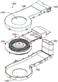
现在参考图24至27,提供了双模式泵送装置138B的一个实施例的各种视图。双模式泵送装置138B可包括外壳139B,该外壳139B可容纳双模式泵送装置138B的部件,例如用于产生流经双模式泵送装置138B的流体的一个或多个转子140B、用于对转子140B供电的一个或多个马达141B、一个或多个热电装置94B、一个或多个主换热器96B和/或一个或多个排放换热器100B。如所示实施例中示出,双模式泵送装置138B可包括联接到单个马达141B的两个转子140B、单个热电装置94B、单个主侧换热器96B和单个排放侧换热器100B。在一些实施例中,双模式泵送装置可包括联接至每个转子的单独的马达。此外,双模式泵送装置94B可包括两个或更多热电装置94B、两个或更多主侧换热器96B和/或两个或更多排放侧换热器100B。Referring now to Figures 24-27, various views of one embodiment of a dual
如所示实施例中示出,转子140B可包括多个例如叶轮的翅片,用于产生流经双模式泵送装置138B的外壳139B的流体。双模式泵送装置138B可包括外壳139B的第一侧上的第一入口142B和外壳139B的另一侧上的第二入口144B。例如,第一入口142B可定位在外壳139B的顶侧上,第二入口144B可定位在外壳139B的底侧上。转子140B可通过第一入口142B和第二入口144B吸取例如空气的流体并将流体通过第一出口146B和第二出口148B排出。第一入口142B和第一出口146B可经由例如板150B的部件与第二入口144B和第二出口148B分开。优选地,板150B也可定位在转子140B周围以实现大致防漏的密封从而减小流体混合而降低系统效率的可能性。As shown in the illustrated embodiment,
如所示实施例中示出,经第二入口144B吸取的流体可流经通过外壳139B形成的管道98B并在经第二出口148B被排出之前流过主侧换热器96B。相应地,流经第二入口144B的流体可在离开第二出口148B之前被转换成被调节的流体97B。相似地,经第一入口142B吸取的流体可流经由外壳139B形成的管道99B,并在经第一出口146B被排出之前流过排放侧换热器100B。相应地,流经第一入口142B的流体可在离开第一出口146B之前被转换成排放流体101B。为了减小经由第二入口144B将大量排放流体101B再次引入系统的可能性,有利的是增大第二入口144B与第一出口146B之间的距离或在第二入口144B和/或第一出口146B周围包括护罩。As shown in the illustrated embodiment, fluid drawn through
通过第二入口144B和/或第二出口148B的流可大致垂直于通过管道98B的流。通过第二入口144B和第二出口148B的流可大致平行。如所示实施例中示出,第二入口144B可定位在外壳139B的底侧上,第二出口148B可定位在外壳139B的顶侧上。在所示实施例中,流体可通过管道98B从外壳139B的前侧流到后侧。The flow through the
通过第一入口142B和/或第一出口146B的流可大致垂直于通过管道99B的流。通过第一入口142B和第一出口146B的流可大致垂直。如所示实施例中示出,第一入口142B可定位在外壳139B的顶侧上,第二出口146B可定位在外壳139B的左侧和/或右侧上。在所示实施例中,流体可通过管道99B从外壳139B的前侧流到后侧。Flow through
尽管上文将流经入口142B、144B、出口146B、148B和管道98B、99B的流体描述为大致相互垂直,也可设想使用其他角度。在一些实施例中,由流体流的方向形成的角度可以小于90度。例如,由流体流的方向形成的角度可以是大约10度至大约80度之间、大约20度至大约70度之间、大约30度至大约60度之间、大约40度至大约45度之间、这些范围内的任何角度子范围、或这些范围内的任何角度。在一些实施例中,由流体流的方向形成的角度可以大于90度。例如,由流体流的方向形成的角度可以是大约100度至大约170度之间、大约110度至大约160度之间、大约120度至大约150度之间、大约135度至大约140度之间、这些范围内的任何角度子范围、或这些范围内的任何角度。Although the fluids flowing through
尽管仅描述了双模式泵送装置138B,双模式泵送装置138A可包括与双模式泵送装置138B和/或上述与双模式泵送装置138B有关的任何变型相同或相似的特征。相应地,双模式泵送装置138A的相似部件将在本申请中标识为在标号后面具有后缀“A”。Although only dual
图28-34示出了气候受控座椅组件30的另一实施例。尽管该实施例关于座椅32和座椅32的部件进行描述,应理解的是,该系统还可应用到靠背34和靠背34的部件。另外,如上所述,本实施例也可用于其它类型的支承组件和其它冷却/加热应用。28-34 illustrate another embodiment of a climate-controlled
首先参考图28,示出了座椅32的一个实施例,其中移除了覆盖物因而暴露垫子72。垫子72的层也已经被移除以暴露这些层下面的结构。如所示实施例中示出,座椅32可包括流体分配系统76B,来自热模块的被调节的空气97B可通过该流体分配系统76B被输送到就座的乘员。流体分配系统76B可定位在座椅32的大腿区域42处或附近。座椅32可包括另一流体分配系统77B,流体可通过该流体分配系统77B被聚集并向排放换热器100B分配以产生待排放到周围大气的排放流体101B。流体分配系统77B可定位成处于或接近座椅32的中央区域和/或座部区域40。相应地,在所示实施例中,被调节的空气97B可在大腿区域42处或附近被输送到乘员并且流体可在中央区域和/或座部区域40处或附近被聚集和吸取。还设想这种布置可以反转,使得被调节的空气97B在中央区域40处或附近被输送到乘员并且流体可在大腿区域42处或附近被聚集和吸取。在一些实施例中,流体分配系统76B、77B两者都可用于向乘员输送被调节的空气97B或者可用于向排放换热器100B聚集和吸取流体以产生待排放到周围大气的排放流体101B。Referring first to FIG. 28 , one embodiment of the
如所示实施例中示出,流体分配系统76B可包括通路78B,来自热模块的被调节的空气97B可流经该通路78B。通路78B可与通道80B流体连通。通道80B可有利地在座椅32的更大面积上分配被调节的空气97B,使得被调节的空气97B的冷却或加热效果在该更大的面积上传播,而不是集中在通路78B。通道80B可朝座椅32的侧部69、71横向向外延伸和/或可朝座椅32的前侧64和/或后侧66的向前/向后方向上延伸。As shown in the illustrated embodiment, the
流体分配系统77B可具有与流体分配系统76B相似的结构。如所示实施例中示出,流体分配系统77B可包括通路79B,流体可通过该通路79B被聚集和朝向排放换热器100B抽取以产生待排放到周围大气的排放流体101B。通路79B可与通道123B流体连通。通道123B可有利地允许在座椅32的更大面积上吸取流体,使得流体流在该更大的面积上传播,而不是集中在通路79B。通道123B可朝座椅32的侧部69、71横向向外延伸和/或可朝座椅32的前侧64和/或后侧66的向前/向后方向上延伸。例如,通道123B可包括定位在座椅32的中央区域的向后更远处的部分85B。
下面参考图29,流体分配系统76B、77B的一者或两者可包括位于通道80B、123B与垫子72之间的层120。如所示实施例中示出,层120可定位在通路78B、79B上方。这样的布置可有益地维持通道80B、123B与例如垫子72的上覆盖层之间的间隙。这可减小上覆盖层坍塌到通路78B、79B上和/或通道80B、123B的部分上的可能性,该可能性可能限制通过流体分配系统76B、77B的流量。在一些实施例中,层120可由具有一定程度弹性的材料例如薄塑料膜形成。层120可以是半透或不透的层以减少从通路78B、79B紧邻上方的流体传递。层120还可以是隔绝层或半隔绝层以减少横跨层120的热传递。Referring now to FIG. 29 , one or both of the
下面参考图30,一部分或整体通道80B、123B与可填充有透气材料,例如间隔织物,该透气材料可为乘员提供支承同时仍允许空气流过该材料。如所示实施例中示出,间隔织物125定位在流体分配系统77B的通道123B的一部分内,包括部分85B。间隔织物125可设计成维持通道123B的底部以及层120与通道123B和/或层120上方的部件例如垫子72之间的分离。这可有益地维持流体腔室,该流体腔室允许流体在通道123B、层120和通道123B和层120上方的部件之间横向和/或向上的运动,即使当乘员坐在座椅32上、倾向于使这些腔室坍塌时和/或当通道123B受到低于大气压的压力、也倾向于使这些腔室坍塌时亦是如此。Referring now to Figure 30, a portion or the entirety of the
在所示实施例中,流体分配系统76B内没有设置间隔织物125。由于流体分配系统76B中存在正压力(即,高于大气压的压力),腔室坍塌的可能性较小,即使当受到就座的乘员的压力时亦是如此。此外,施加到大腿区域42的力的量通常低于施加到座椅的座部区域40的力的量,因此与流体分配系统77B相比进一步减小了腔室坍塌的可能性。在一些实施例中,间隔织物125可定位在流体分配系统76B的部分或全部通道80B中。In the illustrated embodiment, no
下面参考图31,垫子72可定位在流体分配系统76B、77B上方从而为乘员提供支承并减小通道80B、123B将影响乘员舒适度的可能性。垫子72可包括一个或多个开口129B,该开口与流体分配系统76B流体连通以允许被调节的空气97B流过垫子72并流向就座的乘员。如所示实施例中示出,开口129B可定位成处于或邻近乘员坐在座椅32上时大腿的大致位置。通过这样定位开口129B,被调节的流体97B可集中在乘员处或附近的区域,使得被调节的流体97B的效果对于乘员更加明显。这可有益地降低用于实现相同调节效果的总能耗。尽管所示实施例包括大致围绕处于或邻近乘员大腿的大致位置的区域的八个开口129B,可以设想开口129B的其它布置方式,包括使用更少或更多的开口129B。Referring now to Figure 31, the
垫子72可包括一个或多个与流体分配系统77B流体连通的开口131B,流体可通过所述开口被聚集和分配到排放换热器100B以产生待排放到周围大气的排放流体101B。如所示实施例中示出,开口131B可定位成处于或邻近乘员在坐在座椅32上时大腿的大致位置。通过这样定位开口131B,回收的流体可集中在乘员或其附近的区域,使得回收流体的效果对于乘员将更加明显。这可有益地降低用于实现相同效果的总能耗。尽管所示实施例包括大致围绕处于或邻近乘员大腿的大致位置的区域的八个开口131B,可以设想开口131B的其它布置方式,包括使用更少或更多的开口131B。图34示出了座椅32的示意性的剖视图。
下面参考图32,所示的座椅32的下侧示出通路78B、79B的位置。下面参考图33,泵送装置,例如双模式泵送装置138B可连接到用于支承垫子72和座椅32的其它部分的座椅框架73的下侧。如所示实施例中示出,双模式泵送装置138B可包括第一入口(例如,图25的142B),其定位成与通路79B流体连通以使流体能被吸取通过通路79B、进入外壳139B并穿过排放侧换热器(例如,图25的100B),排放流体101B可在该处产生并被排放到外壳139B外面。在一些实施例中,排放流体101B可被排向座椅框架73的下侧。双模式泵送装置138B可包括第二入口144B,其中第二出口(例如,图25的148B)定位成与通路78B流体连通以使流体能被吸取通过第二入口144B、进入外壳139B并通过主侧换热器(例如,图25的96B),被调节的流体(例如,图25的97B)可在该处产生并被引入通路78B,在通路78B经由流体分配系统76B被分配到座椅32的各部分。如所示实施例中示出,第二入口144B可包括延长的管道152B以允许双模式泵送装置138B从不容易与排放流体101B混合的位置吸取空气。Referring now to Figure 32, the underside of the
图35-38示出了气候受控座椅组件30的另一实施例。尽管该实施例关于靠背34和靠背34的部件进行描述,应理解的是,该系统还可应用到座椅32和座椅32的部件。此外,如上所述,本实施例也可用于其它类型的支承组件和/或其它冷却/加热应用。35-38 illustrate another embodiment of a climate-controlled
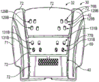
首先参考图35,示出了靠背34的一个实施例,其中移除了覆盖物因而暴露垫子72。垫子72的层也已经被移除以暴露这些层下面的结构。如所示实施例中示出,靠背34可包括流体分配系统76A,来自热模块的被调节的空气97A可通过该流体分配系统76A被输送到就座的乘员。流体分配系统76A可定位在靠背34的上背部区域63或附近。靠背34可包括另一流体分配系统77A,流体可通过该流体分配系统77A被聚集并向排放换热器100A分配以产生待排放到周围大气的排放流体101A。流体分配系统77A可定位成处于或接近靠背34的腰部区域62。相应地,在所示实施例中,被调节的空气97A可在上背部区域63或附近被输送到乘员并且流体可在腰部区域62被聚集和吸取。还设想这种布置可以反转,使得被调节的空气97A在腰部区域62处或附近被输送到乘员并且流体可在上背部区域63处或附近被聚集和吸取。在一些实施例中,流体分配系统76A、77A两者都可用于向乘员输送被调节的空气97A或者可用于向排放换热器100A聚集和吸取流体以产生待排放到周围大气的排放流体101A。Referring first to FIG. 35 , one embodiment of the
如所示实施例中示出,流体分配系统76A可包括通路78A,来自热模块的被调节的空气97A可流经该通路78A。通路78A可与通道80A流体连通。通道80A可有利地在靠背34的更大面积上分配被调节的空气97A,使得被调节的空气97A的冷却或加热效果在该更大的面积上传播,而不是集中在通路78A。通道80A可朝靠背34的侧部57、59横向向外延伸和/或可在朝靠背34的顶侧58或后侧60的向上/向下方向上延伸。As shown in the illustrated embodiment,
流体分配系统77A可具有与流体分配系统76A相似的结构。如所示实施例中示出,流体分配系统77A包括通路79A,流体可通过该通路79A被朝向排放换热器100A聚集和抽取以产生待排放到周围大气的排放流体101A。通路79A可与通道123A流体连通。通道123A可有利地允许在靠背34的更大面积上吸取流体,使得流体流在该更大的面积上传播,而不是集中在通路79A。通道123A可朝靠背34的侧部57、59横向向外延伸和/或可在朝靠背34的顶侧58或底侧60的向上/向下方向上延伸。例如,通道123A可包括定位在朝向靠背34的底侧60的向下更远处的部分85A。
流体分配系统76A、77A的一者或两者可包括位于通道80A、123A与垫子72之间的层120。如所示实施例中示出,层120可定位在通路79A上方。这样的布置可有益地维持通道123A与例如垫子72的上覆盖层之间的间隙。这可减小上覆盖层坍塌到通路79A上和/或通道123A的部分上的可能性,该可能性可能限制通过流体分配系统77A的流量。在一些实施例中,层120可由具有一定程度弹性的材料例如薄塑料膜形成。层120可以是半透或不透的层以减少从通路79A紧邻上方的流体传递。层120还可以是隔绝层或半隔绝层以减少横跨层120的热传递。尽管未显示,通道80A、123A的一部分或整体可填充有透气材料,例如间隔织物,该透气材料可为乘员提供支承并仍允许空气流过该材料。One or both of the
下面参考图36,垫子72可定位在流体分配系统76A、77A上方从而为乘员提供支承并减小通道80A、123A将影响乘员舒适度的可能性。垫子72可包括一个或多个开口129A,该开口与流体分配系统76A流体连通以允许被调节的空气97A流过垫子72并流向就座的乘员。如所示实施例中示出,开口129A可定位成处于或邻近乘员坐在靠背34时上背部的大致位置。通过这样定位开口129A,被调节的流体97B可集中在乘员处或附近的区域,使得被调节的流体97A的效果对于乘员更加明显。这可有益地降低用于实现相同调节效果的总能耗。尽管所示实施例包括定位成大致围绕处于或邻近乘员上背部的大致位置的区域的四个开口129A,可以设想开口129A的其它布置,包括使用更少或更多的开口129A。36, the
垫子72可包括与流体分配系统77A流体连通的一个或多个开口131A,流体可通过所述开口被聚集和分配到排放换热器100A以产生待排放到周围大气的排放流体101A。如所示实施例中示出,开口131A可定位成处于或邻近乘员在坐在靠背34上时下背部或腰部区域的大致位置。通过这样定位开口131A,回收的流体可集中在乘员处或其附近的区域,使得回收流体的效果对于乘员将更加明显。这可有益地降低用于实现相同效果的总能耗。尽管所示实施例包括定位成大致围绕处于或邻近乘员下背部的大致位置的区域的十二个开口131A,可以设想开口131A的其它布置,包括使用更少或更多的开口131A。
下面参考图37,所示的靠背34的后视图示出通路78A、79A的位置。下面参考图38,泵送装置,例如双模式泵送装置138A可连接到用于支承垫子72和靠背34的其它部分的靠背座椅框架75的后侧。如所示实施例中示出,双模式泵送装置138A可包括第一入口,其定位成与通路79A流体连通以使流体能被吸取通过通路79A、进入外壳139A并穿过排放侧换热器,排放流体101A可在该处产生并被排放到外壳139A外面。在一些实施例中,排放流体101A可被排向靠背框架75的后侧。双模式泵送装置138A可包括第二入口144A,其中第二出口定位成与通路78A流体连通以使流体能被吸取通过第二入口144A、进入外壳139A并通过主侧换热器,被调节的流体可在该处产生并被引入通路78A,在通路78A经由流体分配系统76A被分配到靠背34的各部分。如所示实施例中示出,第二入口144A可包括管道152A以允许双模式泵送装置138A从不容易与排放流体101A混合的位置吸取空气。Referring next to Figure 37, a rear view of the
参考图39,气候受控座椅组件30具有座椅32和靠背34。如所示实施例中示出,座椅32可包括被调节的流体97B被导向乘员的区域和流体被抽离乘员的区域。此外,靠背34可包括被调节的流体97A被导向乘员的区域和流体被抽离乘员的区域。本实施例可使用关于前文的图28-38描述的系统。Referring to FIG. 39 , the climate-controlled
应理解的是,参照图28-39的上述实施例可用于其它类型的支承组件和/或应用,且不需要与本文所述的附加实施例组合使用。It should be understood that the above-described embodiments with reference to Figures 28-39 may be used with other types of support assemblies and/or applications and need not be used in combination with the additional embodiments described herein.
为了有助于描述本发明的实施例,使用了顶、底、前、后、左、右、侧、上方和下方等词语来说明附图。此外,本文已使用下列术语。单数形式的“一”、“一个”和“所述”包括复数形式,除非上下文另有说明。因此,例如,参考一个对象包括参考一个或多个对象。术语“该”是指一个、两个或更多,并通常应用于对部分或全部数量的选择。术语“多个”是指两个或更多对象。术语“大约”或“约”是指数量、尺寸、大小、形式、参数、形状和其它不需要精确、但可以按需要接近和/或更大或更小的特征,反应可接受的公差、转换因素、四舍五入、测量误差等以及其它本领域已知的因素。术语“大致”是指所引用的特征、参数或值不需要精确实现,但其偏差或将变化,包括例如公差、测量误差、测量精确度限制和其它本领域已知的因素,可在不妨碍该特征本应提供的效果的情况下发生。然而,应理解的是,示意实施例可定位于或定向于各种期望的位置。To help describe the embodiments of the invention, the terms top, bottom, front, rear, left, right, side, above, and below have been used to describe the drawings. In addition, the following terms have been used herein. The singular forms "a," "an," and "the" include the plural unless the context dictates otherwise. Thus, for example, reference to an object includes reference to one or more objects. The term "the" refers to one, two or more, and is generally applied to the selection of some or all of the quantity. The term "plurality" refers to two or more objects. The terms "about" or "about" refer to quantities, dimensions, sizes, forms, parameters, shapes, and other features that do not need to be precise, but can be approximated and/or larger or smaller as desired, reflecting acceptable tolerances, transformations factors, rounding, measurement errors, etc., as well as other factors known in the art. The term "substantially" means that the recited feature, parameter, or value need not be precisely realized, but deviations thereof, including, for example, tolerances, measurement errors, measurement accuracy limitations and other factors known in the art, may be made without prejudice to occurs without the effect the feature is supposed to provide. It should be understood, however, that the illustrative embodiments may be positioned or oriented in various desired locations.
尽管前述优选实施例已经显示、说明和指出特定的新颖特征,但应理解的是,本领域的技术人员可对所示设备的细节的形式进行各种省略、替代和变化及其使用而不脱离本发明的精神。因此,本发明的保护范围不应受到前述说明的限制,前述说明仅用于示出而不是限制本发明的保护范围。While the foregoing preferred embodiments have been shown, described and indicated with particular novel features, it should be understood that various omissions, substitutions and changes in the form and use of the details of the apparatus shown may be made by those skilled in the art without departing from spirit of the present invention. Therefore, the protection scope of the present invention should not be limited by the foregoing description, which is only used to illustrate rather than limit the protection scope of the present invention.
Claims (82)
Priority Applications (1)
| Application Number | Priority Date | Filing Date | Title |
|---|---|---|---|
| CN202010966848.5A CN112224100B (en) | 2014-05-09 | 2015-05-07 | Climate control assembly |
Applications Claiming Priority (3)
| Application Number | Priority Date | Filing Date | Title |
|---|---|---|---|
| US201461991310P | 2014-05-09 | 2014-05-09 | |
| US61/991,310 | 2014-05-09 | ||
| PCT/US2015/029701 WO2015171901A1 (en) | 2014-05-09 | 2015-05-07 | Climate control assembly |
Related Child Applications (1)
| Application Number | Title | Priority Date | Filing Date |
|---|---|---|---|
| CN202010966848.5A Division CN112224100B (en) | 2014-05-09 | 2015-05-07 | Climate control assembly |
Publications (2)
| Publication Number | Publication Date |
|---|---|
| CN106458070A CN106458070A (en) | 2017-02-22 |
| CN106458070B true CN106458070B (en) | 2020-10-16 |
Family
ID=54393002
Family Applications (2)
| Application Number | Title | Priority Date | Filing Date |
|---|---|---|---|
| CN202010966848.5A Active CN112224100B (en) | 2014-05-09 | 2015-05-07 | Climate control assembly |
| CN201580024389.6A Active CN106458070B (en) | 2014-05-09 | 2015-05-07 | climate control components |
Family Applications Before (1)
| Application Number | Title | Priority Date | Filing Date |
|---|---|---|---|
| CN202010966848.5A Active CN112224100B (en) | 2014-05-09 | 2015-05-07 | Climate control assembly |
Country Status (6)
| Country | Link |
|---|---|
| US (3) | US10160356B2 (en) |
| JP (2) | JP6672170B2 (en) |
| KR (2) | KR102449808B1 (en) |
| CN (2) | CN112224100B (en) |
| DE (1) | DE112015002175T5 (en) |
| WO (2) | WO2015171901A1 (en) |
Families Citing this family (42)
| Publication number | Priority date | Publication date | Assignee | Title |
|---|---|---|---|---|
| US7587901B2 (en) | 2004-12-20 | 2009-09-15 | Amerigon Incorporated | Control system for thermal module in vehicle |
| US20080087316A1 (en) | 2006-10-12 | 2008-04-17 | Masa Inaba | Thermoelectric device with internal sensor |
| WO2009036077A1 (en) | 2007-09-10 | 2009-03-19 | Amerigon, Inc. | Operational control schemes for ventilated seat or bed assemblies |
| KR20170064568A (en) | 2008-02-01 | 2017-06-09 | 젠썸 인코포레이티드 | Condensation and humidity sensors for thermoelectric devices |
| US9121414B2 (en) | 2010-11-05 | 2015-09-01 | Gentherm Incorporated | Low-profile blowers and methods |
| WO2013052823A1 (en) | 2011-10-07 | 2013-04-11 | Gentherm Incorporated | Thermoelectric device controls and methods |
| US9989267B2 (en) | 2012-02-10 | 2018-06-05 | Gentherm Incorporated | Moisture abatement in heating operation of climate controlled systems |
| US9662962B2 (en) | 2013-11-05 | 2017-05-30 | Gentherm Incorporated | Vehicle headliner assembly for zonal comfort |
| KR102252584B1 (en) | 2014-02-14 | 2021-05-14 | 젠썸 인코포레이티드 | Conductive convective climate controlled assemblies |
| CN112224100B (en) | 2014-05-09 | 2023-08-22 | 金瑟姆股份公司 | Climate control assembly |
| EP3218942B1 (en) | 2014-11-14 | 2020-02-26 | Charles J. Cauchy | Heating and cooling technologies |
| US11639816B2 (en) | 2014-11-14 | 2023-05-02 | Gentherm Incorporated | Heating and cooling technologies including temperature regulating pad wrap and technologies with liquid system |
| US11857004B2 (en) | 2014-11-14 | 2024-01-02 | Gentherm Incorporated | Heating and cooling technologies |
| JP6480215B2 (en) * | 2015-03-06 | 2019-03-06 | 株式会社タチエス | Vehicle seat |
| JP2019514783A (en) | 2016-04-28 | 2019-06-06 | ジェンサーム オートモーティブ システムズ チャイナリミテッド | Occupant support device and temperature control system therefor |
| DE102016013205A1 (en) * | 2016-11-08 | 2018-05-09 | Gentherm Gmbh | tempering |
| JP6756240B2 (en) * | 2016-11-08 | 2020-09-16 | トヨタ紡織株式会社 | Vehicle seat blower and vehicle seat |
| JP6743684B2 (en) * | 2016-12-22 | 2020-08-19 | トヨタ紡織株式会社 | Vehicle seat blower and vehicle seat |
| US10596936B2 (en) | 2017-05-04 | 2020-03-24 | Ford Global Technologies, Llc | Self-retaining elastic strap for vent blower attachment to a back carrier |
| US20200079258A1 (en) | 2017-05-23 | 2020-03-12 | Ts Tech Co., Ltd. | Conveyance seat |
| WO2018221422A1 (en) * | 2017-05-31 | 2018-12-06 | 株式会社クラベ | Ventilation mat |
| DE102017209680A1 (en) * | 2017-06-08 | 2018-12-13 | Mahle International Gmbh | Temperierungsschicht |
| US10507745B2 (en) | 2017-08-29 | 2019-12-17 | Ford Global Technologies, Llc | Seating assembly with thermoelectric devices |
| US10252652B2 (en) * | 2017-08-29 | 2019-04-09 | Ford Global Technologies, Llc | Seating assembly with heating and cooling |
| US10821803B2 (en) | 2017-08-29 | 2020-11-03 | Ford Global Technologies, Llc | Vehicle seat with cooling fluidflow |
| CN108185719A (en) * | 2017-12-22 | 2018-06-22 | 陆嘉禾 | A kind of health-care mattress |
| US10500994B1 (en) | 2018-06-08 | 2019-12-10 | Ford Global Technologies, Llc | Temperature controlled ventilation system for seating assembly |
| US11279206B1 (en) * | 2018-06-25 | 2022-03-22 | Zoox, Inc. | Heating ventilation and air conditioning (HVAC) system with zonal control |
| DE202018103650U1 (en) * | 2018-06-27 | 2019-09-30 | Bernhard Scheuring | Insert for air conditioning |
| US11223004B2 (en) | 2018-07-30 | 2022-01-11 | Gentherm Incorporated | Thermoelectric device having a polymeric coating |
| JP7608337B2 (en) | 2018-11-30 | 2025-01-06 | ジェンサーム インコーポレイテッド | Thermoelectric regulation system and method |
| US11152557B2 (en) | 2019-02-20 | 2021-10-19 | Gentherm Incorporated | Thermoelectric module with integrated printed circuit board |
| US11524784B2 (en) | 2019-07-31 | 2022-12-13 | B/E Aerospace, Inc. | Ventilated seat assembly with active air flow |
| DE102020107329A1 (en) * | 2019-12-17 | 2021-06-17 | Gentherm Gmbh | Fan module for vehicle seats |
| KR102817538B1 (en) * | 2020-03-04 | 2025-06-05 | 현대자동차주식회사 | Ventilation device for slim seat of vehicle |
| KR20210156021A (en) * | 2020-06-17 | 2021-12-24 | 현대자동차주식회사 | Ventilation apparatus for vehicle seat |
| US12479143B2 (en) | 2021-12-20 | 2025-11-25 | Lear Corporation | System and method of making a mesh cushion |
| US12358411B2 (en) * | 2022-04-01 | 2025-07-15 | Lear Corporation | Vehicle seat subassemblies |
| US12454111B2 (en) | 2022-05-11 | 2025-10-28 | Lear Corporation | Tool to manufacture a cushion |
| US12326742B2 (en) | 2022-12-22 | 2025-06-10 | Lear Corporation | Valve and actuator assembly for a fluid system in a vehicle seat assembly |
| US12337738B2 (en) | 2022-11-09 | 2025-06-24 | Lear Corporation | Fluid system for a vehicle seat assembly |
| US12509343B2 (en) | 2023-02-28 | 2025-12-30 | Lear Corporation | Automated trench manufacturing and assembly for attaching trim covers to a cushion assembly |
Citations (6)
| Publication number | Priority date | Publication date | Assignee | Title |
|---|---|---|---|---|
| US6166905A (en) * | 1998-06-17 | 2000-12-26 | Nec Corporation | Sealed type casing |
| CN1306613A (en) * | 1998-05-12 | 2001-08-01 | 阿美里根公司 | Thermoelectric heat exchanger |
| CN1513699A (en) * | 2002-12-18 | 2004-07-21 | W.E.T.����ϵͳ�ɷݹ�˾ | Air -conditioning seat and air-conditioning device used on ventilation seat |
| CN101808839A (en) * | 2007-07-23 | 2010-08-18 | 阿美里根公司 | Radial thermoelectric device assembly |
| CN101879872A (en) * | 2004-12-20 | 2010-11-10 | 阿美里根公司 | Control system for vehicle temperature modules |
| CN102019866A (en) * | 2009-09-17 | 2011-04-20 | 现代自动车株式会社 | Heat exchanger having thermoelectric element |
Family Cites Families (169)
| Publication number | Priority date | Publication date | Assignee | Title |
|---|---|---|---|---|
| US3136577A (en) | 1961-08-02 | 1964-06-09 | Stevenson P Clark | Seat temperature regulator |
| US3137523A (en) | 1963-09-20 | 1964-06-16 | Karner Frank | Air conditioned seat |
| US4152094A (en) | 1975-10-31 | 1979-05-01 | Hitachi, Ltd. | Axial fan |
| DE2940650A1 (en) | 1979-10-06 | 1981-04-16 | Papst-Motoren Kg, 7742 St Georgen | AXIAL FAN |
| JPS5670868U (en) | 1979-11-06 | 1981-06-11 | ||
| JPS59145396A (en) | 1982-11-09 | 1984-08-20 | パプスト・モ−ト−レン・ゲ−エムベ−ハ−・ウント・コ−・カ−ゲ− | Direct current small-sized ventilator |
| DE3609095A1 (en) | 1985-03-28 | 1986-10-09 | Keiper Recaro GmbH & Co KG, 5630 Remscheid | Vehicle seat |
| US4806081A (en) | 1986-11-10 | 1989-02-21 | Papst-Motoren Gmbh And Company Kg | Miniature axial fan |
| US4671567A (en) | 1986-07-03 | 1987-06-09 | The Jasper Corporation | Upholstered clean room seat |
| US4923248A (en) | 1988-11-17 | 1990-05-08 | Steve Feher | Cooling and heating seat pad construction |
| DE3928883A1 (en) | 1989-08-31 | 1991-03-14 | Grammer Ag | UPHOLSTERY PART FOR A SEAT |
| US5002336A (en) | 1989-10-18 | 1991-03-26 | Steve Feher | Selectively cooled or heated seat and backrest construction |
| US5077709A (en) | 1990-10-15 | 1991-12-31 | Steve Feher | Rotating timepiece dial face construction with included movable decorative objects |
| US5117638A (en) | 1991-03-14 | 1992-06-02 | Steve Feher | Selectively cooled or heated seat construction and apparatus for providing temperature conditioned fluid and method therefor |
| JPH05147423A (en) * | 1991-11-29 | 1993-06-15 | Nippondenso Co Ltd | Air conditioner for vehicle |
| US5449275A (en) | 1993-05-11 | 1995-09-12 | Gluszek; Andrzej | Controller and method for operation of electric fan |
| US5385382A (en) | 1993-10-06 | 1995-01-31 | Ford Motor Company | Combination seat frame and ventilation apparatus |
| US5524439A (en) | 1993-11-22 | 1996-06-11 | Amerigon, Inc. | Variable temperature seat climate control system |
| US5626021A (en) * | 1993-11-22 | 1997-05-06 | Amerigon, Inc. | Variable temperature seat climate control system |
| US5597200A (en) | 1993-11-22 | 1997-01-28 | Amerigon, Inc. | Variable temperature seat |
| US6085369A (en) | 1994-08-30 | 2000-07-11 | Feher; Steve | Selectively cooled or heated cushion and apparatus therefor |
| JP3064016B2 (en) | 1995-02-14 | 2000-07-12 | ヴェー イー テー オートモーティヴ システムズ アーゲー | Air conditioning sheet |
| US5888261A (en) | 1995-08-03 | 1999-03-30 | Fortune; William S. | Rotating element fume collection apparatus |
| SE504973C2 (en) | 1995-09-14 | 1997-06-02 | Walinov Ab | Fan unit included in a ventilated vehicle seat |
| SE504942C2 (en) | 1995-09-14 | 1997-06-02 | Walinov Ab | Device for ventilating a vehicle seat |
| US6263530B1 (en) | 1996-09-24 | 2001-07-24 | Steve Feher | Selectively cooled or heated cushion and apparatus therefor |
| DE19703516C1 (en) | 1997-01-31 | 1998-05-07 | Daimler Benz Ag | Vehicle seat with upholstery heating and cooling |
| JP3705395B2 (en) | 1997-04-22 | 2005-10-12 | 本田技研工業株式会社 | Automotive seat structure |
| JP3637395B2 (en) | 1997-04-28 | 2005-04-13 | 本田技研工業株式会社 | Vehicle air conditioner and seat heating / cooling device |
| US5850741A (en) | 1997-06-09 | 1998-12-22 | Feher; Steve | Automotive vehicle steering wheel heating and cooling apparatus |
| US5887304A (en) | 1997-07-10 | 1999-03-30 | Von Der Heyde; Christian P. | Apparatus and method for preventing sudden infant death syndrome |
| DE19830797B4 (en) * | 1997-07-14 | 2007-10-04 | Denso Corp., Kariya | Vehicle seat air conditioner |
| US5927817A (en) | 1997-08-27 | 1999-07-27 | Lear Corporation | Ventilated vehicle seat assembly |
| DE19745521C2 (en) | 1997-10-15 | 2001-12-13 | Daimler Chrysler Ag | Upholstery for a vehicle seat |
| JPH11137371A (en) | 1997-11-10 | 1999-05-25 | Aisin Seiki Co Ltd | Ventilation sheet device |
| WO1999037924A1 (en) | 1998-01-23 | 1999-07-29 | Comair Rotron, Inc. | Low profile motor |
| DE19804100C1 (en) | 1998-02-03 | 1999-05-12 | Daimler Chrysler Ag | Automobile seat with incorporated ventilation |
| DE19804284C2 (en) | 1998-02-04 | 2002-03-14 | Daimler Chrysler Ag | vehicle seat |
| DE19805173C1 (en) * | 1998-02-10 | 1999-06-02 | Daimler Chrysler Ag | Motor vehicle seat with ventilation |
| US6606866B2 (en) * | 1998-05-12 | 2003-08-19 | Amerigon Inc. | Thermoelectric heat exchanger |
| DE19842979C1 (en) | 1998-09-19 | 1999-12-02 | Daimler Chrysler Ag | heated seat for vehicle |
| DE19851979C2 (en) | 1998-11-11 | 2000-08-31 | Daimler Chrysler Ag | Temperature sensor for an air-conditioned vehicle seat |
| DE19851209C1 (en) | 1998-12-09 | 2000-04-13 | Daimler Chrysler Ag | Back rest for motor vehicle seat has lordosis support with fan blower connected by duct to porous ventilation cover layer |
| US6552464B1 (en) | 1999-11-09 | 2003-04-22 | Siemens Canada Limited | Totally integrated engine cooling module for DC motors |
| DE10009128C1 (en) | 2000-02-26 | 2001-08-16 | Wet Automotive Systems Ag | Device for ventilation of a vehicle seat |
| DE10024880C1 (en) | 2000-05-19 | 2001-09-06 | Daimler Chrysler Ag | Actively-ventilated seat module for automobile passenger seat has ventilated cushion zone with mesh layer between 2 rubber fibre layers |
| SE0002690L (en) | 2000-07-19 | 2002-01-20 | Kongsberg Automotive Ab | Apparatus and method for temperature control and ventilation of a seat |
| WO2002011968A2 (en) | 2000-08-04 | 2002-02-14 | Woodbridge Foam Corporation | Foam element having molded gas passageways and process for production thereof |
| DE10049458A1 (en) | 2000-10-06 | 2002-04-18 | Daimler Chrysler Ag | Upholstery for a vehicle seat |
| DE10054010C1 (en) | 2000-11-01 | 2002-01-03 | Daimler Chrysler Ag | Vehicle seat for open car; has air supply unit with fan and nozzles arranged in upper part of back rest to reduce undesired draughts, where height of fan can be adjusted with respect to back rest |
| DE10054008B4 (en) | 2000-11-01 | 2004-07-08 | Daimlerchrysler Ag | Automobile seat |
| DE10054009B4 (en) | 2000-11-01 | 2005-01-05 | Daimlerchrysler Ag | Wind protection device for an open motor vehicle |
| US6786541B2 (en) | 2001-01-05 | 2004-09-07 | Johnson Controls Technology Company | Air distribution system for ventilated seat |
| US7040710B2 (en) | 2001-01-05 | 2006-05-09 | Johnson Controls Technology Company | Ventilated seat |
| JP2002227798A (en) | 2001-01-31 | 2002-08-14 | Matsushita Electric Ind Co Ltd | Blower |
| DE10105094B4 (en) | 2001-02-05 | 2004-07-08 | W.E.T. Automotive Systems Ag | vehicle seat |
| JP2002234332A (en) * | 2001-02-09 | 2002-08-20 | Matsushita Electric Ind Co Ltd | Air conditioning system for seats |
| US7273981B2 (en) * | 2001-02-09 | 2007-09-25 | Bsst, Llc. | Thermoelectric power generation systems |
| DE10115242B4 (en) | 2001-03-28 | 2005-10-20 | Keiper Gmbh & Co Kg | Vehicle seat with ventilation |
| US6598251B2 (en) | 2001-06-15 | 2003-07-29 | Hon Technology Inc. | Body support system |
| DE10135008B4 (en) | 2001-07-18 | 2006-08-24 | W.E.T. Automotive Systems Ag | Electrical circuit for controlling a climate seat |
| DE20112473U1 (en) | 2001-07-28 | 2002-12-19 | Johnson Controls GmbH, 51399 Burscheid | Air-conditioned upholstery part for a vehicle seat |
| WO2003014634A1 (en) | 2001-08-07 | 2003-02-20 | Bsst Llc | Thermoelectric personal environment appliance |
| US20030039298A1 (en) | 2001-08-22 | 2003-02-27 | Lear Corporation | System and method of vehicle climate control |
| US7071587B2 (en) | 2001-09-07 | 2006-07-04 | Rotys Inc. | Integrated cooler for electronic devices |
| US6855880B2 (en) | 2001-10-05 | 2005-02-15 | Steve Feher | Modular thermoelectric couple and stack |
| US6700052B2 (en) | 2001-11-05 | 2004-03-02 | Amerigon Incorporated | Flexible thermoelectric circuit |
| DE20120516U1 (en) | 2001-12-19 | 2003-04-30 | Johnson Controls GmbH, 51399 Burscheid | Ventilation system for an upholstered part |
| DE10163049C2 (en) | 2001-12-21 | 2003-11-13 | Daimler Chrysler Ag | Automotive seat |
| US7036163B2 (en) | 2002-02-06 | 2006-05-02 | Halo Innovations, Inc. | Furniture cover sheet |
| JP4175000B2 (en) | 2002-02-28 | 2008-11-05 | 松下電器産業株式会社 | Temperature control device and seat incorporating this device |
| JP2004017855A (en) * | 2002-06-18 | 2004-01-22 | Daihatsu Motor Co Ltd | Seat structure for vehicle |
| US6893086B2 (en) | 2002-07-03 | 2005-05-17 | W.E.T. Automotive Systems Ltd. | Automotive vehicle seat insert |
| JP2004073429A (en) | 2002-08-15 | 2004-03-11 | Nhk Spring Co Ltd | Breathable sheet |
| US6857697B2 (en) | 2002-08-29 | 2005-02-22 | W.E.T. Automotive Systems Ag | Automotive vehicle seating comfort system |
| JP2004161137A (en) | 2002-11-13 | 2004-06-10 | Denso Corp | Vehicular seat air conditioner |
| DE10259621B4 (en) | 2002-12-18 | 2005-12-01 | W.E.T. Automotive Systems Ag | Vehicle seat and associated air conditioning device |
| JP4013765B2 (en) * | 2003-01-14 | 2007-11-28 | 株式会社デンソー | Vehicle seat air conditioner |
| US7168758B2 (en) | 2003-06-05 | 2007-01-30 | Igb Automotive Ltd. | Modular comfort assembly for occupant support |
| US6954944B2 (en) | 2003-06-23 | 2005-10-18 | Steve Feher | Air conditioned helmet apparatus |
| US7124593B2 (en) | 2003-09-02 | 2006-10-24 | Steve Feher | Temperature conditioning apparatus for the trunk of a human body |
| US7338117B2 (en) * | 2003-09-25 | 2008-03-04 | W.E.T. Automotive System, Ltd. | Ventilated seat |
| US7425034B2 (en) | 2003-10-17 | 2008-09-16 | W.E.T. Automotive Systems Ag | Automotive vehicle seat having a comfort system |
| DE602005025089D1 (en) * | 2004-03-09 | 2011-01-13 | Panasonic Corp | AIR CONDITIONED SEAT AND SELF-USING AIR CONDITIONING |
| JP2005287537A (en) | 2004-03-31 | 2005-10-20 | T S Tec Kk | Car seat |
| US7114771B2 (en) | 2004-05-25 | 2006-10-03 | Amerigon, Inc. | Climate controlled seat |
| US7828050B2 (en) * | 2004-09-02 | 2010-11-09 | Honda Motor Co., Ltd. | Vehicle seat air-conditioner and vehicle temperature controller |
| JP2006069376A (en) * | 2004-09-02 | 2006-03-16 | Honda Motor Co Ltd | Vehicle seat air conditioner |
| US20060087160A1 (en) | 2004-10-25 | 2006-04-27 | Hanh Dong | Apparatus for providing fluid through a vehicle seat |
| US20070262621A1 (en) | 2004-10-25 | 2007-11-15 | Hanh Dong | Apparatus for providing fluid through a vehicle seat |
| US20060137099A1 (en) | 2004-12-28 | 2006-06-29 | Steve Feher | Convective cushion with positive coefficient of resistance heating mode |
| US7272936B2 (en) | 2004-12-28 | 2007-09-25 | Steve Feher | Variable temperature cushion and heat pump |
| US20070251016A1 (en) | 2004-12-28 | 2007-11-01 | Steve Feher | Convective seating and sleeping systems |
| WO2006117690A2 (en) * | 2005-02-17 | 2006-11-09 | W.E.T. Automotive Systems Ag | Active ventilation systems for vehicle seats |
| US20060214480A1 (en) * | 2005-03-23 | 2006-09-28 | John Terech | Vehicle seat with thermal elements |
| US7827805B2 (en) | 2005-03-23 | 2010-11-09 | Amerigon Incorporated | Seat climate control system |
| US20060244289A1 (en) | 2005-04-02 | 2006-11-02 | Johnson Controls Technology Company | Control system for seat |
| KR20060106507A (en) * | 2005-04-09 | 2006-10-12 | 한라공조주식회사 | Car seat air conditioner |
| US20060254284A1 (en) * | 2005-05-11 | 2006-11-16 | Yuji Ito | Seat air conditioning unit |
| WO2006124835A1 (en) | 2005-05-16 | 2006-11-23 | Amerigon, Inc. | Ventilated headrest |
| JP2007126047A (en) * | 2005-11-04 | 2007-05-24 | Denso Corp | Vehicle seat air conditioner |
| ATE547285T1 (en) | 2006-01-30 | 2012-03-15 | Amerigon Inc | COOLING SYSTEM FOR A CONTAINER IN A VEHICLE |
| US7862113B2 (en) | 2006-01-30 | 2011-01-04 | Igb Automotive Ltd. | Modular comfort assembly diffuser bag having integral air mover support |
| JP4899523B2 (en) | 2006-02-20 | 2012-03-21 | 日本電産株式会社 | Centrifugal fan |
| US20070200398A1 (en) | 2006-02-28 | 2007-08-30 | Scott Richard Wolas | Climate controlled seat |
| US7806961B2 (en) | 2006-03-17 | 2010-10-05 | Em Innovative Properties Company | Control interface for a variable speed fan device |
| KR20080114681A (en) | 2006-04-03 | 2008-12-31 | 몰레큘러 임프린츠 인코퍼레이티드 | Lithography Imprinting System |
| JP2007297034A (en) * | 2006-04-07 | 2007-11-15 | Denso Corp | Heating/cooling device |
| US7591507B2 (en) * | 2006-04-13 | 2009-09-22 | Amerigon Incorporated | Tie strap for climate controlled seat |
| US8539624B2 (en) | 2006-05-31 | 2013-09-24 | Gentherm Incorporated | Structure based fluid distribution system |
| US8222511B2 (en) | 2006-08-03 | 2012-07-17 | Gentherm | Thermoelectric device |
| US7708338B2 (en) | 2006-10-10 | 2010-05-04 | Amerigon Incorporated | Ventilation system for seat |
| US20080087316A1 (en) | 2006-10-12 | 2008-04-17 | Masa Inaba | Thermoelectric device with internal sensor |
| EP2567637B1 (en) | 2006-10-13 | 2014-08-06 | Gentherm Incorporated | Air conditioning bed |
| US7665803B2 (en) | 2006-11-01 | 2010-02-23 | Amerigon Incorporated | Chair with air conditioning device |
| US20080124234A1 (en) | 2006-11-02 | 2008-05-29 | Jaime Echazarreta | Fan tray assembly shaped Venturi |
| US7640754B2 (en) | 2006-12-14 | 2010-01-05 | Amerigon Incorporated | Insert duct piece for thermal electric module |
| US20080164733A1 (en) | 2007-01-08 | 2008-07-10 | Giffin Steven C | Clamp for climate control device |
| US20080166224A1 (en) | 2007-01-09 | 2008-07-10 | Steve Craig Giffin | Blower housing for climate controlled systems |
| US9105808B2 (en) | 2007-01-10 | 2015-08-11 | Gentherm Incorporated | Thermoelectric device |
| US8143554B2 (en) | 2007-03-16 | 2012-03-27 | Amerigon Incorporated | Air warmer |
| US20090000031A1 (en) | 2007-06-29 | 2009-01-01 | Steve Feher | Multiple convective cushion seating and sleeping systems and methods |
| US20090033130A1 (en) | 2007-07-02 | 2009-02-05 | David Marquette | Fluid delivery systems for climate controlled seats |
| US9105809B2 (en) | 2007-07-23 | 2015-08-11 | Gentherm Incorporated | Segmented thermoelectric device |
| WO2009036077A1 (en) | 2007-09-10 | 2009-03-19 | Amerigon, Inc. | Operational control schemes for ventilated seat or bed assemblies |
| JP5103114B2 (en) * | 2007-09-25 | 2012-12-19 | トヨタ紡織株式会社 | Air conditioning sheet |
| US9125497B2 (en) | 2007-10-15 | 2015-09-08 | Gentherm Incorporated | Climate controlled bed assembly with intermediate layer |
| JP4486990B2 (en) * | 2007-11-12 | 2010-06-23 | ビステオン グローバル テクノロジーズ インコーポレイテッド | Temperature control sheet |
| KR20170064568A (en) | 2008-02-01 | 2017-06-09 | 젠썸 인코포레이티드 | Condensation and humidity sensors for thermoelectric devices |
| US20090218855A1 (en) | 2008-02-26 | 2009-09-03 | Amerigon Incorporated | Climate control systems and devices for a seating assembly |
| US20090211619A1 (en) | 2008-02-26 | 2009-08-27 | Marlow Industries, Inc. | Thermoelectric Material and Device Incorporating Same |
| ITTO20080159A1 (en) | 2008-03-04 | 2009-09-05 | Johnson Electric Moncalieri Srl | MOTORIZED ELECTRIC APPLIANCE, IN A PARTICULAR ELECTRIC MOTOR-DRIVER. |
| US7950735B2 (en) * | 2008-04-07 | 2011-05-31 | GM Global Technology Operations LLC | Temperature controlled vehicle seats |
| EP2112381A3 (en) | 2008-04-21 | 2014-04-30 | Ebm-Papst St. Georgen GmbH & CO. KG | Fan arrangement |
| JP5430085B2 (en) * | 2008-06-20 | 2014-02-26 | 株式会社クラベ | Seat with built-in blower |
| CN102098947B (en) | 2008-07-18 | 2014-12-10 | 阿美里根公司 | Climate controlled bed assembly |
| JP2010052494A (en) * | 2008-08-26 | 2010-03-11 | Denso Corp | Seat blower |
| US8653763B2 (en) | 2008-09-12 | 2014-02-18 | Delta Electronics, Inc. | Ventilator and its impeller |
| DE202009017049U1 (en) | 2008-12-21 | 2010-05-12 | W.E.T. Automotive Systems Ag | aerator |
| US8575518B2 (en) | 2009-01-28 | 2013-11-05 | Gentherm Incorporated | Convective heater |
| WO2010129803A1 (en) | 2009-05-06 | 2010-11-11 | Amerigon, Inc. | Control schemes and features for climate-controlled beds |
| JP5585004B2 (en) | 2009-05-29 | 2014-09-10 | 日本電産株式会社 | Centrifugal fan |
| US8332975B2 (en) | 2009-08-31 | 2012-12-18 | Gentherm Incorporated | Climate-controlled topper member for medical beds |
| KR101114584B1 (en) * | 2009-09-17 | 2012-04-13 | 갑을오토텍(주) | Heating and air conditioning system for vehicle seat |
| DE102010037449B4 (en) * | 2009-09-17 | 2015-03-26 | Kia Motors Corporation | Heating and cooling system for vehicle seat |
| JP2011189764A (en) * | 2010-03-12 | 2011-09-29 | Toyota Industries Corp | Air conditioner for vehicle |
| US20110271994A1 (en) | 2010-05-05 | 2011-11-10 | Marlow Industries, Inc. | Hot Side Heat Exchanger Design And Materials |
| US8544942B2 (en) | 2010-05-27 | 2013-10-01 | W.E.T. Automotive Systems, Ltd. | Heater for an automotive vehicle and method of forming same |
| US20120080911A1 (en) | 2010-08-27 | 2012-04-05 | Amerigon Incorporated | Fluid distribution features for climate controlled seating assemblies |
| US9121414B2 (en) | 2010-11-05 | 2015-09-01 | Gentherm Incorporated | Low-profile blowers and methods |
| WO2012061777A2 (en) | 2010-11-05 | 2012-05-10 | Amerigon Incorporated | Low-profile blowers and methods |
| KR101241160B1 (en) * | 2010-12-09 | 2013-03-13 | 현대자동차주식회사 | Cool and hot air circulation seat module in vehicle |
| US8727434B2 (en) * | 2011-04-07 | 2014-05-20 | Toyota Boshoku Kabushiki Kaisha | Vehicle seat |
| WO2013052823A1 (en) | 2011-10-07 | 2013-04-11 | Gentherm Incorporated | Thermoelectric device controls and methods |
| US9989267B2 (en) | 2012-02-10 | 2018-06-05 | Gentherm Incorporated | Moisture abatement in heating operation of climate controlled systems |
| JP5870773B2 (en) * | 2012-03-08 | 2016-03-01 | トヨタ紡織株式会社 | Vehicle seat with air conditioner |
| JP2013203196A (en) * | 2012-03-28 | 2013-10-07 | Panasonic Corp | Air conditioner for vehicle |
| US9451723B2 (en) | 2012-07-06 | 2016-09-20 | Gentherm Incorporated | System and method for thermoelectrically cooling inductive charging assemblies |
| DE202012011717U1 (en) | 2012-07-25 | 2013-10-28 | W.E.T. Automotive Systems Ag | Nackenwärmer |
| DE102013000231B4 (en) | 2012-07-25 | 2021-09-02 | Gentherm Gmbh | Air conveyor |
| DE102012023996A1 (en) | 2012-09-28 | 2014-06-12 | W.E.T. Automotive Systems Ag | Tempering device for handles, in particular of steering devices |
| KR101955392B1 (en) | 2012-12-21 | 2019-05-30 | 젠썸 캐나다 유엘씨 | Device and method for improving the response time of a temperature control device |
| DE102013010180A1 (en) | 2013-01-07 | 2014-07-10 | W.E.T. Automotive Systems Ag | Treatment device for the therapeutic temperature control of body parts |
| US20160030234A1 (en) | 2013-03-12 | 2016-02-04 | Gentherm Incorporated | Devices, systems and methods of cooling the skin |
| CN105121224A (en) | 2013-03-15 | 2015-12-02 | 金瑟姆股份公司 | Thermally Regulated Beverage Holders and Cases |
| US9428033B2 (en) | 2013-12-18 | 2016-08-30 | Hyundai Motor Company | Air-conditioning apparatus for vehicle |
| DE112013007739T5 (en) * | 2013-12-31 | 2016-12-29 | Gentherm Automotive Systems (China) Ltd. | ventilation system |
| CN112224100B (en) | 2014-05-09 | 2023-08-22 | 金瑟姆股份公司 | Climate control assembly |
| US10297274B2 (en) * | 2016-06-01 | 2019-05-21 | Spectra Logic, Corp. | Shingled magnetic recording raid scheme |
-
2015
- 2015-05-07 CN CN202010966848.5A patent/CN112224100B/en active Active
- 2015-05-07 US US15/309,749 patent/US10160356B2/en active Active
- 2015-05-07 WO PCT/US2015/029701 patent/WO2015171901A1/en not_active Ceased
- 2015-05-07 CN CN201580024389.6A patent/CN106458070B/en active Active
- 2015-05-07 JP JP2016564972A patent/JP6672170B2/en active Active
- 2015-05-07 KR KR1020167034643A patent/KR102449808B1/en active Active
- 2015-05-07 KR KR1020227033664A patent/KR102637609B1/en active Active
- 2015-05-07 DE DE112015002175.2T patent/DE112015002175T5/en active Pending
- 2015-11-10 US US14/937,624 patent/US10457173B2/en active Active
-
2016
- 2016-11-08 WO PCT/US2016/060999 patent/WO2017083308A1/en not_active Ceased
-
2018
- 2018-12-19 US US16/226,104 patent/US10647232B2/en active Active
-
2020
- 2020-03-04 JP JP2020037068A patent/JP7011678B2/en active Active
Patent Citations (6)
| Publication number | Priority date | Publication date | Assignee | Title |
|---|---|---|---|---|
| CN1306613A (en) * | 1998-05-12 | 2001-08-01 | 阿美里根公司 | Thermoelectric heat exchanger |
| US6166905A (en) * | 1998-06-17 | 2000-12-26 | Nec Corporation | Sealed type casing |
| CN1513699A (en) * | 2002-12-18 | 2004-07-21 | W.E.T.����ϵͳ�ɷݹ�˾ | Air -conditioning seat and air-conditioning device used on ventilation seat |
| CN101879872A (en) * | 2004-12-20 | 2010-11-10 | 阿美里根公司 | Control system for vehicle temperature modules |
| CN101808839A (en) * | 2007-07-23 | 2010-08-18 | 阿美里根公司 | Radial thermoelectric device assembly |
| CN102019866A (en) * | 2009-09-17 | 2011-04-20 | 现代自动车株式会社 | Heat exchanger having thermoelectric element |
Also Published As
| Publication number | Publication date |
|---|---|
| US10647232B2 (en) | 2020-05-12 |
| JP2017514743A (en) | 2017-06-08 |
| KR20170015919A (en) | 2017-02-10 |
| US10457173B2 (en) | 2019-10-29 |
| US10160356B2 (en) | 2018-12-25 |
| DE112015002175T5 (en) | 2017-01-19 |
| KR20220134059A (en) | 2022-10-05 |
| KR102637609B1 (en) | 2024-02-15 |
| WO2015171901A1 (en) | 2015-11-12 |
| JP6672170B2 (en) | 2020-03-25 |
| US20160137110A1 (en) | 2016-05-19 |
| CN112224100B (en) | 2023-08-22 |
| CN106458070A (en) | 2017-02-22 |
| KR102449808B1 (en) | 2022-09-29 |
| CN112224100A (en) | 2021-01-15 |
| JP7011678B2 (en) | 2022-01-26 |
| US20190202327A1 (en) | 2019-07-04 |
| JP2020079088A (en) | 2020-05-28 |
| WO2017083308A1 (en) | 2017-05-18 |
| US20170267140A1 (en) | 2017-09-21 |
Similar Documents
| Publication | Publication Date | Title |
|---|---|---|
| CN106458070B (en) | climate control components | |
| USRE47574E1 (en) | Structure based fluid distribution system | |
| EP2329988B1 (en) | Climate controlled seat assembly | |
| US7475464B2 (en) | Climate controlled seat | |
| US7708338B2 (en) | Ventilation system for seat | |
| US8434314B2 (en) | Climate control systems and methods | |
| US20060214480A1 (en) | Vehicle seat with thermal elements | |
| US20090033130A1 (en) | Fluid delivery systems for climate controlled seats |
Legal Events
| Date | Code | Title | Description |
|---|---|---|---|
| C06 | Publication | ||
| PB01 | Publication | ||
| SE01 | Entry into force of request for substantive examination | ||
| SE01 | Entry into force of request for substantive examination | ||
| GR01 | Patent grant | ||
| GR01 | Patent grant |