CN106457109B - Filters and Cartridges - Google Patents
Filters and Cartridges Download PDFInfo
- Publication number
- CN106457109B CN106457109B CN201580032511.4A CN201580032511A CN106457109B CN 106457109 B CN106457109 B CN 106457109B CN 201580032511 A CN201580032511 A CN 201580032511A CN 106457109 B CN106457109 B CN 106457109B
- Authority
- CN
- China
- Prior art keywords
- filter
- filter cartridge
- main
- outflow
- cartridge
- Prior art date
- Legal status (The legal status is an assumption and is not a legal conclusion. Google has not performed a legal analysis and makes no representation as to the accuracy of the status listed.)
- Active
Links
Images


Classifications
-
- F—MECHANICAL ENGINEERING; LIGHTING; HEATING; WEAPONS; BLASTING
- F02—COMBUSTION ENGINES; HOT-GAS OR COMBUSTION-PRODUCT ENGINE PLANTS
- F02M—SUPPLYING COMBUSTION ENGINES IN GENERAL WITH COMBUSTIBLE MIXTURES OR CONSTITUENTS THEREOF
- F02M35/00—Combustion-air cleaners, air intakes, intake silencers, or induction systems specially adapted for, or arranged on, internal-combustion engines
- F02M35/02—Air cleaners
- F02M35/024—Air cleaners using filters, e.g. moistened
- F02M35/02416—Fixing, mounting, supporting or arranging filter elements; Filter element cartridges
-
- B—PERFORMING OPERATIONS; TRANSPORTING
- B01—PHYSICAL OR CHEMICAL PROCESSES OR APPARATUS IN GENERAL
- B01D—SEPARATION
- B01D46/00—Filters or filtering processes specially modified for separating dispersed particles from gases or vapours
- B01D46/56—Filters or filtering processes specially modified for separating dispersed particles from gases or vapours with multiple filtering elements, characterised by their mutual disposition
- B01D46/62—Filters or filtering processes specially modified for separating dispersed particles from gases or vapours with multiple filtering elements, characterised by their mutual disposition connected in series
-
- B—PERFORMING OPERATIONS; TRANSPORTING
- B01—PHYSICAL OR CHEMICAL PROCESSES OR APPARATUS IN GENERAL
- B01D—SEPARATION
- B01D45/00—Separating dispersed particles from gases or vapours by gravity, inertia, or centrifugal forces
- B01D45/12—Separating dispersed particles from gases or vapours by gravity, inertia, or centrifugal forces by centrifugal forces
- B01D45/16—Separating dispersed particles from gases or vapours by gravity, inertia, or centrifugal forces by centrifugal forces generated by the winding course of the gas stream, the centrifugal forces being generated solely or partly by mechanical means, e.g. fixed swirl vanes
-
- B—PERFORMING OPERATIONS; TRANSPORTING
- B01—PHYSICAL OR CHEMICAL PROCESSES OR APPARATUS IN GENERAL
- B01D—SEPARATION
- B01D46/00—Filters or filtering processes specially modified for separating dispersed particles from gases or vapours
- B01D46/0002—Casings; Housings; Frame constructions
- B01D46/0005—Mounting of filtering elements within casings, housings or frames
-
- B—PERFORMING OPERATIONS; TRANSPORTING
- B01—PHYSICAL OR CHEMICAL PROCESSES OR APPARATUS IN GENERAL
- B01D—SEPARATION
- B01D46/00—Filters or filtering processes specially modified for separating dispersed particles from gases or vapours
- B01D46/10—Particle separators, e.g. dust precipitators, using filter plates, sheets or pads having plane surfaces
-
- B—PERFORMING OPERATIONS; TRANSPORTING
- B01—PHYSICAL OR CHEMICAL PROCESSES OR APPARATUS IN GENERAL
- B01D—SEPARATION
- B01D46/00—Filters or filtering processes specially modified for separating dispersed particles from gases or vapours
- B01D46/42—Auxiliary equipment or operation thereof
- B01D46/4227—Manipulating filters or filter elements, e.g. handles or extracting tools
-
- B—PERFORMING OPERATIONS; TRANSPORTING
- B01—PHYSICAL OR CHEMICAL PROCESSES OR APPARATUS IN GENERAL
- B01D—SEPARATION
- B01D46/00—Filters or filtering processes specially modified for separating dispersed particles from gases or vapours
- B01D46/52—Particle separators, e.g. dust precipitators, using filters embodying folded corrugated or wound sheet material
- B01D46/521—Particle separators, e.g. dust precipitators, using filters embodying folded corrugated or wound sheet material using folded, pleated material
- B01D46/522—Particle separators, e.g. dust precipitators, using filters embodying folded corrugated or wound sheet material using folded, pleated material with specific folds, e.g. having different lengths
-
- B—PERFORMING OPERATIONS; TRANSPORTING
- B01—PHYSICAL OR CHEMICAL PROCESSES OR APPARATUS IN GENERAL
- B01D—SEPARATION
- B01D50/00—Combinations of methods or devices for separating particles from gases or vapours
- B01D50/20—Combinations of devices covered by groups B01D45/00 and B01D46/00
-
- F—MECHANICAL ENGINEERING; LIGHTING; HEATING; WEAPONS; BLASTING
- F02—COMBUSTION ENGINES; HOT-GAS OR COMBUSTION-PRODUCT ENGINE PLANTS
- F02M—SUPPLYING COMBUSTION ENGINES IN GENERAL WITH COMBUSTIBLE MIXTURES OR CONSTITUENTS THEREOF
- F02M35/00—Combustion-air cleaners, air intakes, intake silencers, or induction systems specially adapted for, or arranged on, internal-combustion engines
- F02M35/02—Air cleaners
- F02M35/0201—Housings; Casings; Frame constructions; Lids; Manufacturing or assembling thereof
-
- F—MECHANICAL ENGINEERING; LIGHTING; HEATING; WEAPONS; BLASTING
- F02—COMBUSTION ENGINES; HOT-GAS OR COMBUSTION-PRODUCT ENGINE PLANTS
- F02M—SUPPLYING COMBUSTION ENGINES IN GENERAL WITH COMBUSTIBLE MIXTURES OR CONSTITUENTS THEREOF
- F02M35/00—Combustion-air cleaners, air intakes, intake silencers, or induction systems specially adapted for, or arranged on, internal-combustion engines
- F02M35/02—Air cleaners
- F02M35/0212—Multiple cleaners
- F02M35/0216—Multiple cleaners arranged in series, e.g. pre- and main filter in series
-
- F—MECHANICAL ENGINEERING; LIGHTING; HEATING; WEAPONS; BLASTING
- F02—COMBUSTION ENGINES; HOT-GAS OR COMBUSTION-PRODUCT ENGINE PLANTS
- F02M—SUPPLYING COMBUSTION ENGINES IN GENERAL WITH COMBUSTIBLE MIXTURES OR CONSTITUENTS THEREOF
- F02M35/00—Combustion-air cleaners, air intakes, intake silencers, or induction systems specially adapted for, or arranged on, internal-combustion engines
- F02M35/02—Air cleaners
- F02M35/024—Air cleaners using filters, e.g. moistened
- F02M35/02441—Materials or structure of filter elements, e.g. foams
- F02M35/0245—Pleated, folded, corrugated filter elements, e.g. made of paper
-
- F—MECHANICAL ENGINEERING; LIGHTING; HEATING; WEAPONS; BLASTING
- F02—COMBUSTION ENGINES; HOT-GAS OR COMBUSTION-PRODUCT ENGINE PLANTS
- F02M—SUPPLYING COMBUSTION ENGINES IN GENERAL WITH COMBUSTIBLE MIXTURES OR CONSTITUENTS THEREOF
- F02M35/00—Combustion-air cleaners, air intakes, intake silencers, or induction systems specially adapted for, or arranged on, internal-combustion engines
- F02M35/02—Air cleaners
- F02M35/024—Air cleaners using filters, e.g. moistened
- F02M35/02475—Air cleaners using filters, e.g. moistened characterised by the shape of the filter element
- F02M35/02491—Flat filter elements, e.g. rectangular
-
- F—MECHANICAL ENGINEERING; LIGHTING; HEATING; WEAPONS; BLASTING
- F02—COMBUSTION ENGINES; HOT-GAS OR COMBUSTION-PRODUCT ENGINE PLANTS
- F02M—SUPPLYING COMBUSTION ENGINES IN GENERAL WITH COMBUSTIBLE MIXTURES OR CONSTITUENTS THEREOF
- F02M35/00—Combustion-air cleaners, air intakes, intake silencers, or induction systems specially adapted for, or arranged on, internal-combustion engines
- F02M35/02—Air cleaners
- F02M35/08—Air cleaners with means for removing dust, particles or liquids from cleaners; with means for indicating clogging; with by-pass means; Regeneration of cleaners
- F02M35/084—Dust collection chambers or discharge sockets, e.g. chambers fed by gravity or closed by a valve
-
- F—MECHANICAL ENGINEERING; LIGHTING; HEATING; WEAPONS; BLASTING
- F02—COMBUSTION ENGINES; HOT-GAS OR COMBUSTION-PRODUCT ENGINE PLANTS
- F02M—SUPPLYING COMBUSTION ENGINES IN GENERAL WITH COMBUSTIBLE MIXTURES OR CONSTITUENTS THEREOF
- F02M35/00—Combustion-air cleaners, air intakes, intake silencers, or induction systems specially adapted for, or arranged on, internal-combustion engines
- F02M35/10—Air intakes; Induction systems
- F02M35/104—Intake manifolds
-
- B—PERFORMING OPERATIONS; TRANSPORTING
- B01—PHYSICAL OR CHEMICAL PROCESSES OR APPARATUS IN GENERAL
- B01D—SEPARATION
- B01D2271/00—Sealings for filters specially adapted for separating dispersed particles from gases or vapours
- B01D2271/02—Gaskets, sealings
- B01D2271/022—Axial sealings
-
- B—PERFORMING OPERATIONS; TRANSPORTING
- B01—PHYSICAL OR CHEMICAL PROCESSES OR APPARATUS IN GENERAL
- B01D—SEPARATION
- B01D2271/00—Sealings for filters specially adapted for separating dispersed particles from gases or vapours
- B01D2271/02—Gaskets, sealings
- B01D2271/027—Radial sealings
-
- B—PERFORMING OPERATIONS; TRANSPORTING
- B01—PHYSICAL OR CHEMICAL PROCESSES OR APPARATUS IN GENERAL
- B01D—SEPARATION
- B01D2275/00—Filter media structures for filters specially adapted for separating dispersed particles from gases or vapours
- B01D2275/20—Shape of filtering material
- B01D2275/206—Special forms, e.g. adapted to a certain housing
-
- B—PERFORMING OPERATIONS; TRANSPORTING
- B01—PHYSICAL OR CHEMICAL PROCESSES OR APPARATUS IN GENERAL
- B01D—SEPARATION
- B01D2279/00—Filters adapted for separating dispersed particles from gases or vapours specially modified for specific uses
- B01D2279/30—Filters adapted for separating dispersed particles from gases or vapours specially modified for specific uses for treatment of exhaust gases from IC Engines
Landscapes
- Engineering & Computer Science (AREA)
- Chemical & Material Sciences (AREA)
- Combustion & Propulsion (AREA)
- Mechanical Engineering (AREA)
- General Engineering & Computer Science (AREA)
- Chemical Kinetics & Catalysis (AREA)
- Manufacturing & Machinery (AREA)
- Filtering Of Dispersed Particles In Gases (AREA)
- Filtration Of Liquid (AREA)
- Lubrication Details And Ventilation Of Internal Combustion Engines (AREA)
- Separation By Low-Temperature Treatments (AREA)
- Water Treatment By Sorption (AREA)
Abstract
Description
技术领域technical field
本发明涉及一种过滤器,特别是用于内燃发动机的过滤器,以用于过滤流体,特别是过滤空气,本发明还涉及一种滤筒,特别是用于此类过滤器的滤筒。The present invention relates to a filter, in particular for an internal combustion engine, for filtering fluids, in particular air, and a filter cartridge, in particular for such a filter.
背景技术Background technique
特别是在建筑和农业机械中,发动机的空气过滤变得越来越重要。一方面,因为更高的发动机性能和更严格的排放标准需要增加通过发动机的空气通量,所以使用越来越高效的空气过滤器。另一方面,默认情况下安装的部件组(例如,空调装置)的数量增加。这减少了车辆中可用的安装空间。最后,期望将车辆设计得更小并且更轻,这也是以可用的安装空间为代价的。Especially in construction and agricultural machinery, the air filtration of the engine is becoming more and more important. On the one hand, as higher engine performance and stricter emission standards require increased air flux through the engine, more and more efficient air filters are used. On the other hand, the number of component groups (eg, air conditioning units) that are installed by default increases. This reduces the installation space available in the vehicle. Finally, it is desirable to design vehicles to be smaller and lighter, also at the expense of available installation space.
在易于集成的情况下,此类过滤器的每个部件的特别高的可靠性对于较长的维护间隔而言是重要的。在上述使用领域中,除了高流体通量外,例如由于振动,高机械负载还需要整个系统的特别稳定的构造。With easy integration, a particularly high reliability of each component of such filters is important for longer maintenance intervals. In the aforementioned fields of use, in addition to high fluid fluxes, high mechanical loads, eg due to vibrations, also require a particularly stable configuration of the overall system.
本发明的目的在于提供一种滤筒,特别是副元件,其由于稳固的构造来提供特别高的可靠性。The object of the present invention is to provide a filter cartridge, in particular a secondary element, which offers a particularly high reliability due to its robust construction.
除了空气过滤器的外部尺寸、可能的最大空气通量和过滤器的使用寿命之外,由空气过滤器引起的压力损失是关于空气过滤器的性能评估的决定性参数。In addition to the external dimensions of the air filter, the maximum possible air flux and the service life of the filter, the pressure loss caused by the air filter is a decisive parameter for the performance evaluation of the air filter.
本发明的另一个目的在于为具有给定外部几何形状的过滤器配置压力损失尽可能低的滤筒。Another object of the present invention is to configure a filter cartridge with as low a pressure loss as possible for a filter with a given external geometry.
上述目的分别通过下文将描述的过滤器的实施例的不同方面来解决,特别是用于内燃发动机的过滤器,以用于过滤流体,特别是过滤空气,本发明还涉及一种滤筒,特别是用于此类过滤器的滤筒。如在实施例中能够看出的,能够有利地单独地或者组合地在实施例中提供不同的方面,其中在组合的情况下,单个方面增强其它方面的优点,并且协同的相互作用产生有利的产品。The above objects are respectively solved by different aspects of the embodiments of the filters to be described below, in particular filters for internal combustion engines, for filtering fluids, in particular air, the invention also relates to a filter cartridge, in particular is the cartridge used for this type of filter. As can be seen in the embodiments, the different aspects can be advantageously provided in the embodiments, either individually or in combination, wherein in combination, individual aspects enhance the advantages of the other aspects and synergistic interactions result in advantageous product.
发明内容SUMMARY OF THE INVENTION
该目的通过根据权利要求1的用于过滤流体,特别是空气的、特别是用于内燃发动机的过滤器的滤筒,特别是副滤筒来实现。本发明的其它实施例在从属权利要求中公开。This object is achieved by a filter cartridge, in particular a secondary filter cartridge, according to claim 1 for filtering fluids, in particular air, in particular for filters of internal combustion engines. Further embodiments of the invention are disclosed in the dependent claims.
根据本发明的副滤筒设计成插入到过滤器中在主滤筒的下游处。副滤筒包括流入表面、流出表面和流出方向。此外,副滤筒包括能够沿着流出方向流动所经过的过滤器本体以及支撑过滤器本体的滤筒框架。滤筒框架包括用于将过滤器的过滤器内部分隔成净化侧和未处理侧的密封件,以及在过滤器本体和滤筒框架之间的粘合连接。密封件和粘合连接的分离构型能够实现粘合连接的大体更稳定的构型。The secondary filter cartridge according to the invention is designed to be inserted into the filter downstream of the main filter cartridge. The secondary filter cartridge includes an inflow surface, an outflow surface and an outflow direction. In addition, the secondary filter cartridge includes a filter body through which the flow can flow in the outflow direction, and a filter cartridge frame supporting the filter body. The filter cartridge frame includes a seal for separating the filter interior of the filter into clean and untreated sides, and an adhesive connection between the filter body and the filter cartridge frame. The separated configuration of the seal and the adhesive connection enables a generally more stable configuration of the adhesive connection.
在本发明的优选实施例中,密封件设计成径向作用于主流动方向,并且特别地大致垂直于主流动方向围绕副滤筒周向地延伸。密封件能够包括多孔橡胶。In a preferred embodiment of the invention, the seal is designed to act radially on the main flow direction and in particular extend circumferentially around the secondary filter cartridge substantially perpendicular to the main flow direction. The seal can comprise porous rubber.
特别优选的是提出,滤筒框架的支撑部分围绕过滤器本体周向地延伸,并且支撑区段在内侧上包括用于接收粘合连接的粘合材料的内边缘,特别地是凹槽。这使得能够在过滤器本体和滤筒框架之间实现机械上特别稳定的连接。特别地,能够提出,凹槽的深度在主流动方向的方向上延伸。It is particularly preferred to provide that the support portion of the filter cartridge frame extends circumferentially around the filter body and that the support section comprises on the inside an inner edge, in particular a groove, of adhesive material for receiving the adhesive connection. This enables a mechanically particularly stable connection between the filter body and the filter cartridge frame. In particular, it can be provided that the depth of the groove extends in the direction of the main flow direction.
在本发明的另一实施例中,滤筒框架的密封件接收区段围绕过滤器本体外部周向地延伸。特别是当移除和安装副滤筒时,作用在密封件上的剪切力由密封件接收区段所吸收。In another embodiment of the invention, the seal receiving section of the filter cartridge frame extends circumferentially around the outside of the filter body. In particular when the secondary filter cartridge is removed and installed, the shear forces acting on the seal are absorbed by the seal receiving section.
一个实施例提出,粘合连接包括聚氨酯,并且特别是发泡的。特别地,粘合连接能够部分地穿透过滤器本体,并且以此方式能够确保过滤器本体和滤筒框架之间的特别强的粘合连接。One embodiment proposes that the adhesive connection comprises polyurethane, and in particular is foamed. In particular, the adhesive connection can partially penetrate the filter body, and in this way a particularly strong adhesive connection between the filter body and the filter cartridge frame can be ensured.
在本发明的另一实施例中,能够提出,滤筒框架在流出侧包括覆盖流出表面的格栅。这增加了副滤筒在高压差下的抗塌陷强度。特别地,格栅能够与滤筒框架一起形成一体。In another embodiment of the invention, it can be provided that the filter cartridge frame comprises, on the outflow side, a grid covering the outflow surface. This increases the collapse resistance of the secondary cartridge under high pressure differentials. In particular, the grille can be integrated with the filter cartridge frame.
在滤筒(特别地,副滤筒,其也具有它自身的发明点)的一个实施例中提出,滤筒包括主流入表面、流出表面和主流动方向。此外,滤筒包括能够沿着主流动方向流动所通过的过滤器本体,以及支撑过滤器本体的滤筒框架。滤筒框架优选地包括用于将过滤器的过滤器内部分隔成净化侧和未净化侧的密封件,以及优选在流入侧的把手区域。把手区域进一步设计成使得经由把手区域流入过滤器本体和手动移除滤筒是可能的。以此方式,此区域被扩大,借助于该把手区域实现了至过滤器本体中的流入。因为通常,无论如何存在手动操作滤筒的可能性,特别是用于安装和移除滤筒的可能性,通过设计把手区域,由滤筒引起的压降或压力损失显著减小,以便待过滤的流体流动通过其。In one embodiment of the filter cartridge (in particular the secondary filter cartridge, which also has its own inventive point) it is proposed that the filter cartridge comprises a main inflow surface, an outflow surface and a main flow direction. Furthermore, the filter cartridge includes a filter body through which flow can be carried out in the main flow direction, and a filter cartridge frame supporting the filter body. The filter cartridge frame preferably includes a seal for separating the filter interior of the filter into a clean side and a raw side, and a handle area, preferably on the inflow side. The handle area is further designed such that flow into the filter body and manual removal of the filter cartridge are possible via the handle area. In this way, this area is enlarged, by means of which the inflow into the filter body is achieved. Since generally, however, there is the possibility of manually operating the filter cartridge, especially for installing and removing the filter cartridge, by designing the handle area, the pressure drop or pressure loss caused by the filter cartridge is significantly reduced in order to be filtered fluid flows through it.
在本发明的优选的另一实施例中,提出在主流入表面的侧向设置辅助流入表面。这为滤筒的总体改进的流入情况提供了滤筒的另外的流入表面,并因此进一步减小了由滤筒引起的压力损失。在本文中,能够特别提出的是,把手区域使得能够实现以侧向邻近于主流入表面的方式流入过滤器本体中。In a preferred further embodiment of the invention, it is proposed to provide an auxiliary inflow surface lateral to the main inflow surface. This provides an additional inflow surface of the filter cartridge for an overall improved inflow profile of the filter cartridge and thus further reduces the pressure loss caused by the filter cartridge. In this context, it can be mentioned in particular that the handle area enables inflow into the filter body in a lateral proximity to the main inflow surface.
优选地,把手区域被设计成把手凹部,并且把手凹部面向过滤器本体。一方面,把手凹部提供了用于将滤筒从其插入位置移除的特别简单的可能性。另一方面,凹部的形状使得流体(特别是)无湍流地流入过滤器本体,特别是至主流入表面和辅助流入表面。Preferably, the handle area is designed as a handle recess, and the handle recess faces the filter body. On the one hand, the handle recess provides a particularly simple possibility for removing the filter cartridge from its insertion position. On the other hand, the shape of the recess provides a turbulent flow of fluid (in particular) into the filter body, in particular to the main inflow surface and the auxiliary inflow surface.
在本发明的一个实施例中提出,在主流动方向上,把手区域大致不突出超过流入表面。而且,过滤器本体能够大致具有平行六面体的形状。In one embodiment of the invention it is proposed that in the main flow direction, the handle area does not substantially protrude beyond the inflow surface. Furthermore, the filter body can generally have the shape of a parallelepiped.
在另外的构型中,过滤器本体配置成Z字形折叠过滤器波纹管,并且特别是过滤器波纹管折叠件的端面之一(即,由折叠的过滤介质的Z字形路线形成的侧面)面向把手区域的方向。由于根据本发明的朝向该端面开放的把手区域的构型,流动的流体被引导到过滤器波纹管折叠件的端面。在端面仅在折叠的过滤介质的净化侧处的单侧密封作用的情况下,端面在折叠件之间的未净化侧未粘合的间隙处部分地保持开放。以此方式,流体能够在端面处流入过滤器波纹管的内部中,而不绕过过滤器本体。以此方式,除了由折叠件边缘形成的正则的主流入表面之外,过滤器波纹管的端面能够用作辅助流入表面,并且能够因此使压力损失最小化。In further configurations, the filter body is configured as a zigzag folded filter bellows, and in particular one of the end faces of the filter bellows fold (ie, the side formed by the zigzag course of the folded filter media) faces Orientation of the handle area. Due to the configuration according to the invention of the handle region which is open towards this end face, the flowing fluid is directed to the end face of the filter bellows fold. In the case of a one-sided sealing action of the end faces only on the clean side of the folded filter medium, the end faces remain partially open at the unbonded gaps on the raw side between the folds. In this way, fluid can flow into the interior of the filter bellows at the end face without bypassing the filter body. In this way, the end face of the filter bellows can serve as an auxiliary inflow surface in addition to the regular main inflow surface formed by the edges of the folds, and pressure losses can thus be minimized.
在本发明的一个特别优选的实施例中,滤筒被设计为副滤筒。特别地,因为在主滤筒的下游的安装空间特别紧凑,其并不总是允许在副滤筒处的流入表面实现为等于主滤筒的总流出表面,因此额外的辅助流入表面对于优化整个过滤器系统是特别重要的。In a particularly preferred embodiment of the invention, the filter cartridge is designed as a secondary filter cartridge. In particular, since the installation space downstream of the main filter cartridge is particularly compact, which does not always allow the inflow surface at the secondary filter cartridge to be realized equal to the total outflow surface of the main filter cartridge, the additional auxiliary inflow surface is therefore essential for optimizing the overall The filter system is particularly important.
在本发明的另外的创造性实施例中提出,在滤筒框架的流出侧设有覆盖流出表面的格栅。特别是在高压差下或者在工作中更换主过滤器元件时,副滤筒的特别高的塌陷压力是重要的。这通过设置流出侧格栅得到决定性的改善。In a further inventive embodiment of the invention it is proposed that a grid covering the outflow surface is provided on the outflow side of the filter cartridge frame. The particularly high collapse pressure of the secondary filter cartridge is important, especially at high differential pressures or when replacing the primary filter element during operation. This is decisively improved by arranging the outflow side grille.
格栅能够优选地与滤筒框架一起形成一体。The grille can preferably be integral with the filter cartridge frame.
根据本发明的过滤器,特别是用于内燃发动机的过滤器,用以过滤流体(特别是空气)的过滤器包括具有未净化侧区域和净化侧区域的过滤器壳体。主过滤器元件可插入到过滤器壳体中并且包括主过滤器元件流入表面、主过滤器元件流动方向、主过滤器元件流出表面以及布置在密封表面上的密封件。例如,主过滤器元件能够具有棱柱形的基本形状。特别地,可以实现通过侧面的流动。密封件用于将过滤器壳体的未净化侧区域与过滤器壳体的净化侧区域流体密封地分隔开。此外,过滤器可选地包括副过滤器元件,该副过滤器元件布置在主过滤器元件的下游并且设有副过滤器元件流入表面、副过滤器元件流动方向和副过滤器元件流出表面。密封表面定位成相对于主过滤器元件的主流动方向倾斜。一方面,倾斜的密封表面在过滤器壳体内在主过滤器元件的下游能够提供一空间,副过滤器元件能够布置在该空间中。同时,由于密封表面相对于主流动方向倾斜地定位,在过滤器壳体中已经实现了主流动方向的偏转。因此,通过流出开口在过滤器壳体上的适当的布置,能够实现流体流在期望方向上的偏转。因此,能够消除壳体下游的另外需要的弯管等。A filter according to the invention, in particular a filter for an internal combustion engine, for filtering fluid, in particular air, comprises a filter housing with a raw-side region and a cleaned-side region. The main filter element is insertable into the filter housing and includes a main filter element inflow surface, a main filter element flow direction, a main filter element outflow surface and a seal arranged on the sealing surface. For example, the main filter element can have a prismatic basic shape. In particular, flow through the sides can be achieved. The seal serves to fluid-tightly separate the raw-side region of the filter housing from the clean-side region of the filter housing. Furthermore, the filter optionally comprises a secondary filter element arranged downstream of the primary filter element and provided with a secondary filter element inflow surface, a secondary filter element flow direction and a secondary filter element outflow surface. The sealing surface is positioned obliquely with respect to the main flow direction of the main filter element. On the one hand, the inclined sealing surface can provide a space within the filter housing downstream of the primary filter element in which the secondary filter element can be arranged. At the same time, a deflection of the main flow direction is already achieved in the filter housing due to the oblique positioning of the sealing surfaces with respect to the main flow direction. Thus, by suitable arrangement of the outflow openings on the filter housing, a deflection of the fluid flow in the desired direction can be achieved. Thus, additionally required elbows or the like downstream of the housing can be eliminated.
密封表面和主流动方向能够特别地定位成在85°到10°之间的角度。在该角度范围内,发生流体流的显著偏转。The sealing surface and the main flow direction can in particular be positioned at an angle between 85° and 10°. In this angular range, significant deflection of the fluid flow occurs.
本发明的一个实施例提出,密封表面是弯曲的,并且特别地定位在筒状侧表面上。借助于密封表面的凹形构型,从主过滤器元件看,可用于主过滤器元件的安装空间能够得到优化,并且为具有适当选择的曲率半径的副元件提供足够的空间。同时,由于密封表面的曲率,根据流出开口的位置,能够以特别简单的方式限定过滤器壳体的流出方向。优选地,筒状侧表面的筒的轴线垂直于主过滤器元件流动方向并且垂直于副过滤器元件流动方向。One embodiment of the invention proposes that the sealing surface is curved and is positioned in particular on the cylindrical side surface. By virtue of the concave configuration of the sealing surface, the installation space available for the main filter element can be optimized as seen from the main filter element and sufficient space is provided for the secondary element with a suitably chosen radius of curvature. At the same time, due to the curvature of the sealing surface, depending on the position of the outflow opening, the outflow direction of the filter housing can be defined in a particularly simple manner. Preferably, the axis of the cylinder of the cylindrical side surface is perpendicular to the main filter element flow direction and perpendicular to the secondary filter element flow direction.
可替代地,密封表面能够定位在平面中。Alternatively, the sealing surface can be positioned in a plane.
本发明的优选实施例提出,密封表面和主过滤器元件流出表面平行地延伸。以此方式,提供了在过滤器壳体的未净化侧和净化侧之间的清楚限定的分隔平面。同时,对于弯曲的密封表面的实施例,提供了过滤器内部的并因此提供了整个过滤器的安装空间得到优化的构型。A preferred embodiment of the present invention provides that the sealing surface and the outflow surface of the main filter element extend parallel. In this way, a clearly defined separation plane between the raw and cleaned sides of the filter housing is provided. At the same time, for the embodiment of the curved sealing surface, an optimized configuration of the installation space inside the filter and thus the entire filter is provided.
优选地,提出了副元件流入表面相对于密封表面平行且以一间距间隔开的方式延伸。以此方式,确保在更换副过滤器元件时,过滤器壳体的净化侧不会被污染。在密封表面的弯曲构型中,提出了也弯曲的副元件流入表面。Preferably, it is proposed that the inflow surface of the secondary element extends parallel to the sealing surface and in a spaced-apart manner. In this way, it is ensured that when the secondary filter element is replaced, the clean side of the filter housing is not contaminated. In the curved configuration of the sealing surface, a secondary element inflow surface that is also curved is proposed.
在本发明的优选实施例中,副过滤器元件的基本形状是平行六面体。这实现了副元件的简单构造,例如,从具有笔直折叠的扁平元件,其中在流入侧和流出侧的折叠件边缘各自形成平面,该平面优选地定位成以由折叠件高度限定的间距彼此平行。In a preferred embodiment of the invention, the basic shape of the secondary filter element is a parallelepiped. This enables a simple construction of secondary elements, eg from flat elements with straight folds, where the edges of the folds on the inflow and outflow sides each form planes, which planes are preferably positioned parallel to each other at a distance defined by the height of the folds .
可替代地,副元件的基本形状能够是具有一个或多个弯曲侧面的棱柱,例如中空筒侧向区段。这能够例如通过弯曲的扁平波纹管来实现。该形状提供了将副过滤器元件适配到弯曲的主过滤器元件流出表面并由此进一步优化安装空间的可能性。Alternatively, the basic shape of the secondary element can be a prism with one or more curved sides, eg a hollow cylinder lateral section. This can be achieved, for example, by means of bent flat bellows. This shape offers the possibility of adapting the secondary filter element to the curved outflow surface of the primary filter element and thereby further optimizing the installation space.
在本发明的优选实施例中,主过滤器元件的基本形状是棱柱。特别地,棱柱的基面和顶面能够是四边形或五边形。四边形或五边形能够具有两个或三个直角、锐角和钝角。本发明的优选实施例提出,从外部观察,棱柱的侧面凸出地弯曲,使得产生例如呈现为筒状侧表面的主过滤器元件流出表面。In a preferred embodiment of the invention, the basic shape of the main filter element is a prism. In particular, the base and top surfaces of the prisms can be quadrilateral or pentagonal. A quadrilateral or pentagon can have two or three right, acute and obtuse angles. A preferred embodiment of the present invention proposes that, viewed from the outside, the sides of the prism are convexly curved, so that a main filter element outflow surface is created which, for example, takes the form of a cylindrical side surface.
本发明的有利实施例提出,主过滤器元件是具有至少两个不同折叠件深度的折叠波纹管。借助于两个不同的折叠件深度,能够在折叠件端面处实现相对于主过滤器元件的主流动方向倾斜的主过滤器元件流出表面。可替代地,通过连续增加的折叠件高度,可以在折叠件边缘处实现相对于主过滤器元件的流出方向倾斜的主过滤器元件流出表面。术语折叠件深度和折叠件高度在本文中同义地进行使用。An advantageous embodiment of the invention proposes that the main filter element is a pleated bellows with at least two different pleat depths. By means of the two different depths of the folds, a main filter element outflow surface which is inclined relative to the main flow direction of the main filter element can be achieved at the front faces of the folds. Alternatively, a main filter element outflow surface that is inclined relative to the outflow direction of the main filter element can be achieved at the edges of the fold by continuously increasing the height of the folds. The terms folder depth and folder height are used synonymously herein.
本发明的有利的实施例提出,过滤器壳体具有流入方向、流出方向以及具有流出开口的流出区域。流出接管能够附接到流出区域,其中流出区域包括用于流出接管的紧固表面,并且紧固表面相对于主过滤器元件流动方向成定位成45°的角度。相对于主流动方向呈45°倾斜的紧固表面特别优选地以此方式位于过滤器壳体的布置上,使得从主过滤器元件流动方向上观察其定位在过滤器壳体内,即,紧固表面不会突出超过过滤器壳体。同时,从与主过滤器元件的主流动方向垂直的方向观察,即例如在主过滤器元件的插入方向上观察,该紧固表面定位在主过滤器元件的下方。安装在该紧固表面上的流出接管现在能够相对容易地在任何方向上分配流出的已过滤流体。An advantageous embodiment of the invention provides that the filter housing has an inflow direction, an outflow direction and an outflow area with outflow openings. The outflow nipple can be attached to the outflow area, wherein the outflow area includes a fastening surface for the outflow nipple, and the fastening surface is positioned at an angle of 45° with respect to the main filter element flow direction. The fastening surface inclined at 45° with respect to the main flow direction is particularly preferably located on the arrangement of the filter housing in such a way that it is positioned in the filter housing as viewed in the main filter element flow direction, ie the fastening The surface will not protrude beyond the filter housing. At the same time, viewed in a direction perpendicular to the main flow direction of the main filter element, ie for example in the insertion direction of the main filter element, the fastening surface is positioned below the main filter element. The outflow nozzle mounted on this fastening surface is now able to distribute outgoing filtered fluid in any direction with relative ease.
本发明的特别优选的实施例提出,流出接管形成为使得流动方向产生45°的偏转。以此方式,仅流出接管在流出区域上(特别是在紧固表面上)的取向与最终流出方向相关。这使得能够以特别有利的方式利用单个部件(即,流出接管)来限定已过滤流体的流出方向。通过在紧固表面上的流出接管的合适取向产生过滤器壳体的最终流出方向。A particularly preferred embodiment of the invention provides that the outflow nozzle is formed such that the flow direction is deflected by 45°. In this way, only the orientation of the outflow nipple on the outflow region, in particular on the fastening surface, is related to the final outflow direction. This makes it possible in a particularly advantageous manner to define the outflow direction of the filtered fluid with a single component, ie the outflow nozzle. The final outflow direction of the filter housing is created by a suitable orientation of the outflow nipple on the fastening surface.
本发明的另外的优选实施例提出,流出接管包括呈现为旋转对称的紧固区域,该紧固区域用于附接在过滤器壳体的紧固表面上。因此,通过流出接管的旋转,能够选定整个过滤器壳体的流出方向的最终确定。以此方式,在过滤器壳体的流入方向与具有一个且同一个部件的过滤器壳体的流出方向之间产生在0°到90°之间的角度范围。A further preferred embodiment of the invention proposes that the outflow nipple comprises a fastening area exhibiting rotational symmetry for attachment on the fastening surface of the filter housing. Therefore, the final determination of the outflow direction of the entire filter housing can be selected by rotating the outflow nozzle. In this way, an angular range between 0° and 90° is created between the inflow direction of the filter housing and the outflow direction of the filter housing with one and the same part.
以相同的方式,能够限定流出方向和紧固表面相对于彼此定位成45°的角度。In the same way, it is possible to define the outflow direction and the positioning of the fastening surface at an angle of 45° with respect to each other.
本发明的设计的另外的可替代实施例提出,紧固表面定位在筒状侧表面上。筒的轴线在本文中优选地定位成垂直于主过滤器元件的主流动方向。此类弯曲的紧固表面优选地与流出接管的相应弯曲的紧固区域组合。然后,流出接管在流出区域处的位置限定过滤器壳体的流出方向。A further alternative embodiment of the design of the invention proposes that the fastening surface is positioned on the cylindrical side surface. The axis of the cartridge is here preferably positioned perpendicular to the main flow direction of the main filter element. Such curved fastening surfaces are preferably combined with corresponding curved fastening regions of the outflow nipple. The position of the outflow nozzle at the outflow region then defines the outflow direction of the filter housing.
优选地,紧固表面和副元件流出表面平行地延伸。这实现了极高的集成度,并因此实现了安装空间的优化。Preferably, the fastening surface and the secondary element outflow surface extend parallel. This enables an extremely high level of integration and thus an optimization of the installation space.
根据本发明,在一个实施例中能够提出,主过滤器元件沿着插入轴线可插入至过滤器壳体中以及可从其移除,其中插入轴线相对于主流动方向定位成一角度,该角度处于90°与在密封表面和主流动方向相对于彼此定位所成的角度之间。根据该实施例,过滤器壳体具有盖,该盖设计成使得在其封闭过滤器壳体的状态下,其在密封表面的方向上对主过滤器元件施加力。由于密封表面的倾斜定位,该力至少部分地转化成轴向力,即,转变为作用在主流动方向的方向上的力。这提供了按压主过滤器元件与其安装在密封表面上的密封件抵靠过滤器壳体上的主过滤器元件位置的力。According to the invention, it can be provided in one embodiment that the main filter element is insertable into and removable from the filter housing along an insertion axis, wherein the insertion axis is positioned at an angle relative to the main flow direction, the angle being at 90° and the angle at which the sealing surface and the main flow direction are positioned relative to each other. According to this embodiment, the filter housing has a cover which is designed such that in its state closing the filter housing it exerts a force on the main filter element in the direction of the sealing surface. Due to the oblique positioning of the sealing surfaces, this force is at least partially transformed into an axial force, ie into a force acting in the direction of the main flow direction. This provides a force to press the main filter element with its seal mounted on the sealing surface against the position of the main filter element on the filter housing.
主滤筒包括流入表面、流出表面以及主流动方向、过滤器本体以及特别地可更换的用于支撑的滤筒框架。滤筒在流出表面的区域中包括用于将过滤器内部分隔成净化侧和未净化侧的密封件,以及用于限定滤筒框架和能够在主流动方向上定位在下游的另外的滤筒之间的间距的间隔结构。借助于间隔结构,即使在极端的使用条件下,例如振动的条件下,也能够保持一个滤筒(例如能够是主滤筒)与布置在下游的另外的滤筒(例如是副滤筒)之间的先前限定的间距。这确保了另外的滤筒不能移出其指定位置并由此不会失去其密封功能和固定功能。The main filter cartridge comprises an inflow surface, an outflow surface and a main flow direction, a filter body and in particular a replaceable cartridge frame for support. The filter cartridge comprises, in the area of the outflow surface, a seal for dividing the interior of the filter into a clean side and a raw side, as well as a seal for delimiting the filter cartridge frame and a further filter cartridge that can be positioned downstream in the main flow direction. spacer structure. Thanks to the spacer structure, it is possible to keep one filter cartridge (which can be the main filter cartridge, for example) and another filter cartridge arranged downstream (for example, the secondary filter cartridge) even under extreme conditions of use, such as vibrations the previously defined spacing between. This ensures that the additional filter cartridge cannot be moved out of its designated position and thus does not lose its sealing and securing function.
在本发明的一个实施例中提出,间隔结构布置在密封件内,特别是在沿着密封件的若干位置处,并且特别地在流出表面的周边处。对于此类构型,能够提出,垂直于另外的滤筒的主流动方向的外周边遵循密封件的形状和尺寸,并因此为间隔结构提供支撑表面。In one embodiment of the invention it is proposed that the spacer structures are arranged within the seal, in particular at several positions along the seal and in particular at the periphery of the outflow surface. For such a configuration, it can be provided that the outer periphery perpendicular to the main flow direction of the further filter cartridge follows the shape and dimensions of the seal and thus provides a support surface for the spacer structure.
本发明的有利的实施例提出,流出表面或/和密封件的密封表面相对于主流动方向定位成在5°到45°之间的角度,特别地是24°±10°的角度,并且特别地是24°±5°的角度。与不成角度的流出表面相比,与主流动方向以此方式成角度的流出表面具有更大的表面积。通常,流出表面或/和密封表面的改善提供了使主流动方向已经在滤筒内或直接在滤筒下游实现偏转的可能性。这节省了安装空间,并且由于较短的流动距离改善了过滤器内的压力损失。An advantageous embodiment of the invention proposes that the outflow surface or/and the sealing surface of the seal be positioned at an angle between 5° and 45°, in particular at an angle of 24°±10°, and in particular with respect to the main flow direction Ground is an angle of 24°±5°. An outflow surface angled in this way to the main flow direction has a larger surface area than an outflow surface that is not angled. Generally, the improvement of the outflow surface or/and the sealing surface provides the possibility to achieve a deflection of the main flow direction already within the filter cartridge or directly downstream of the filter cartridge. This saves installation space and improves pressure losses within the filter due to the shorter flow distance.
有利地,间隔结构与密封件整体形成,特别地与密封件一起模制而成。这使得例如用于密封件的相同的加工步骤同样能够用于具有相同材料和制造的间隔结构。Advantageously, the spacer structure is integrally formed with the seal, in particular moulded together with the seal. This enables, for example, the same processing steps used for seals to also be used for spacer structures of the same material and manufacture.
特别优选的实施例提出,间隔结构设计成,在滤筒的安装状态下对在主流方向上能够布置在下游的另外的滤筒(特别是副滤筒)施加夹紧力或保持力,其中该力将另外的滤筒压入其安装位置。例如,这能够通过由弹性材料制成间隔结构来实现。然后,当滤筒在另外的滤筒之后被插入时,该插入已经能够通过对恰当的几何形状的适当选择来对另外的滤筒施加力。这反过来又改进了过滤器的可靠性,因为另外的滤筒持久地受到将其保持在其指定位置的力的作用。A particularly preferred embodiment provides that the spacer structure is designed in such a way that, in the installed state of the filter cartridge, a clamping force or a holding force is exerted on further filter cartridges (in particular secondary filter cartridges) which can be arranged downstream in the main flow direction, wherein the force the additional filter cartridge into its installation position. This can be achieved, for example, by making the spacer structure from an elastic material. Then, when the filter cartridge is inserted after the further filter cartridge, the insertion can already exert a force on the further filter cartridge by suitable selection of the correct geometry. This in turn improves the reliability of the filter, as the additional filter cartridge is permanently subjected to the force that keeps it in its designated position.
在本发明的优选实施例中,密封件轴向地作用在主流动方向的方向上。这意味着,施加用于密封作用的力平行于流出方向地延伸。In a preferred embodiment of the invention, the seal acts axially in the direction of the main flow direction. This means that the force applied for the sealing effect extends parallel to the outflow direction.
在本发明的实施例中,过滤器本体被实现为过滤器波纹管,特别地具有可变的折叠件高度。借助于可变的折叠件高度,例如能够实现相对于主流动方向倾斜延伸的流出表面。当由一系列的折叠件边缘限定的跨越折叠波纹管的长度的折叠件高度不是恒定的,而是连续地或不连续地变化或者在相邻区段中变化时,Z字形折叠过滤器本体的构型被理解为可变的折叠件高度。优选地,折叠件高度在穿过波纹管的长度上连续地变化,并且进一步优选线性地变化。In an embodiment of the invention, the filter body is realized as a filter bellows, in particular with a variable pleat height. By means of the variable fold height, for example, an outflow surface extending obliquely with respect to the main flow direction can be realized. The zigzag pleated filter body is not constant when the fold height defined by a series of fold edges is not constant across the length of the folded bellows, but varies continuously or discontinuously or in adjacent sections. Configuration is understood as variable fold height. Preferably, the fold height varies continuously over the length through the bellows, and further preferably varies linearly.
该目的还通过一种用于过滤流体、特别是空气,特别是用于内燃发动机的过滤器来解决。根据本发明的过滤器包括过滤器壳体,主滤筒和副滤筒能够插入该过滤器壳体中。主滤筒包括流入表面、流出表面以及主流动方向、过滤器本体和支撑过滤器本体的滤筒框架。副滤筒能够布置在主滤筒的下游。滤筒框架在流出表面的区域中包括用于将过滤器壳体分隔成净化侧和未净化侧的密封件,以及用于限定滤筒框架和副滤筒之间的间距的间隔结构。This object is also solved by a filter for filtering fluids, in particular air, in particular for internal combustion engines. The filter according to the invention comprises a filter housing into which the main filter cartridge and the secondary filter cartridge can be inserted. The main filter cartridge includes an inflow surface, an outflow surface and a main flow direction, a filter body and a filter cartridge frame supporting the filter body. The secondary filter cartridge can be arranged downstream of the main filter cartridge. The filter cartridge frame includes, in the region of the outflow surface, a seal for separating the filter housing into a clean side and a raw side, and a spacer structure for defining the spacing between the filter cartridge frame and the secondary filter cartridge.
在过滤器的有利实施例中提出,过滤器壳体具有大致垂直于主流动方向的插入方向的主流动方向。这使得在插入副滤筒之后能够以此方式插入主滤筒,从而阻止副滤筒移动离开其指定位置。In an advantageous embodiment of the filter it is provided that the filter housing has a main flow direction which is substantially perpendicular to the insertion direction of the main flow direction. This enables the primary filter cartridge to be inserted after the secondary filter cartridge is inserted in such a way that the secondary filter cartridge is prevented from moving out of its designated position.
在优选实施例中提出,副滤筒包括用于接触过滤器壳体的密封件,其中密封件特别地设计成在相对于副滤筒的流动方向径向地作用。因此,不需要在过滤器壳体上在副滤筒的主流动方向的轴向延伸上设置密封表面。相反,在已经插入到指定位置中后,密封件垂直于主流动方向抵靠过滤器壳体是有效的。In a preferred embodiment it is proposed that the secondary filter cartridge comprises a seal for contacting the filter housing, wherein the seal is designed in particular to act radially with respect to the flow direction of the secondary filter cartridge. Therefore, it is not necessary to provide sealing surfaces on the filter housing in the axial extension of the main flow direction of the secondary filter cartridge. Conversely, the seal is effective against the filter housing perpendicular to the main flow direction after it has been inserted into the intended position.
附图说明Description of drawings
现在将参照附图更详细地解释本发明。在附图中:The present invention will now be explained in more detail with reference to the accompanying drawings. In the attached image:
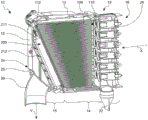
图1是根据本发明的过滤器的实施例的透视的截面图,其具有插入的主滤筒和副滤筒;Figure 1 is a perspective cross-sectional view of an embodiment of a filter according to the present invention with a primary and secondary filter cartridge inserted;
图2是没有副滤筒插入的图1的过滤器;Figure 2 is the filter of Figure 1 without a secondary filter cartridge inserted;
图3是没有主滤筒插入的图1的过滤器;Figure 3 is the filter of Figure 1 without the main filter cartridge inserted;
图4是图1的过滤器的截面图;Figure 4 is a cross-sectional view of the filter of Figure 1;
图5是根据本发明的图1的过滤器的透视的外视图;Figure 5 is a perspective exterior view of the filter of Figure 1 in accordance with the present invention;
图6是根据本发明的具有过滤器本体的副滤筒的透视图;6 is a perspective view of a secondary filter cartridge with a filter body according to the present invention;
图6a是根据本发明的可替代的副滤筒的过滤器本体的透视图;Figure 6a is a perspective view of the filter body of an alternative secondary filter cartridge according to the present invention;
图7和图8是没有过滤器本体的图6的副滤筒的透视图;Figures 7 and 8 are perspective views of the secondary filter cartridge of Figure 6 without the filter body;
图9是图6的过滤器的透视的截面图;Figure 9 is a perspective cross-sectional view of the filter of Figure 6;
图10是图7的过滤器的截面图;Figure 10 is a cross-sectional view of the filter of Figure 7;
图11是主滤筒的透视的前视图;Figure 11 is a perspective front view of the main filter cartridge;
图12是图11的主滤筒的透视的后视图;Figure 12 is a perspective rear view of the main filter cartridge of Figure 11;
图13是图11的主滤筒的透视的截面图;Figure 13 is a perspective cross-sectional view of the main filter cartridge of Figure 11;
图14是没有边缘保护件的图11的主滤筒的透视的后视图;Figure 14 is a perspective rear view of the main filter cartridge of Figure 11 without the edge protector;
图15和图16是流出接管的位置不同的图5的过滤器的透视的外部视图;15 and 16 are perspective external views of the filter of FIG. 5 with different locations of the outflow nozzle;
图17是图5的过滤器的侧视图;Figure 17 is a side view of the filter of Figure 5;
图18是图15的过滤器的侧视图;以及Figure 18 is a side view of the filter of Figure 15; and
图19是图16的过滤器的侧视图。FIG. 19 is a side view of the filter of FIG. 16 .
具体实施方式Detailed ways
参照图1至图5,现在将描述根据本发明的过滤器10的实施例。此类过滤器10例如能够用于建筑或农业机械的进气歧管、压缩机或具有内燃发动机的另外的装置,用以过滤流体,特别是过滤空气。过滤器10包括过滤器壳体12,其可粗略地分成未净化侧区域14和净化侧区域16。1 to 5, an embodiment of a
过滤器100通过沿着主流入方向X进行流动。在流入侧16上,待过滤的流体冲击在粗化模块或预分离模块18上,其在当前情况下设计成旋风分离器块。在旋风分离器块18中,多个单独的预分离单元20在所谓的多旋风分离器块中并联连接。在旋风分离器块18中已经预分离的灰尘和/或水通过排出接管22从过滤器壳体12中移除。The
在旋风分离器块18的下游,待过滤的流体流入主滤筒100。主滤筒100在当前情况下实现为棱柱。主滤筒100的流入表面110并不定位成平行于主滤筒100的流出表面112。相反,流入表面110和流出表面112相对于彼此成角度地定位。在当前情况下,关于期望的表面积,主滤筒100的流入表面110小于主滤筒100的流出表面112。在主滤筒100的流出侧,副滤筒200设置在过滤器壳体12中。副过滤器元件200的主流入表面210取向成朝向主滤筒100的流出表面112,并且特别地布置成平行于该流出表面112。在此实施例中,流出表面212取向成平行于与副滤筒200的主流入表面210。由于主滤筒100的流出表面112的倾斜位置,已经在来自主滤筒100的流体流入时,而且也在来自副滤筒200的流入时,发生主流动方向X的偏转。由于过滤器壳体12在流出区域24中的流出几何形状,正流动的流体被偏转到流出方向Y并且被导向流出接管26。在当前情况下,主流出方向Y大致垂直于主流入方向X。然而,其它流出方向也是可能的。特别地,这将结合图15至图19来更详细地进行解释。Downstream of the
主滤筒100包括主滤筒流入表面110、主滤筒流动方向X1、主滤筒流出表面112以及布置在密封表面114上的密封件116,该密封件116用于将过滤器壳体12流体密封地分隔为未净化侧区域14和净化侧区域16。具有副滤筒流入表面210、副滤筒流动方向Y1和副滤筒流出表面212的副滤筒200布置在主滤筒100的下游。主滤筒100的密封表面114相对于主滤筒100的主流动方向Y1倾斜地定位。特别地,密封表面114以角度α定位,该角度α优选地在5°到45°之间(参见图4),特别地,该角度为24°±10°和24°±5°。在本实施例中,角度α为24°(参见图4)。The
副滤筒流入表面210大致平行于主滤筒100的密封表面114且与其间隔开一间距地延伸。间距小于2cm;在本实施例中,间距为1cm。The secondary filter
图11至图14示出了主滤筒100。主滤筒100包括流入表面110和流出表面112。沿着主流入方向X发生到主滤筒100的流入,并且沿着主流动方向X1发生通过该主滤筒100的流动。主滤筒100包括接纳过滤器本体120的滤筒框架118。过滤器本体120在当前情况下实现成折叠波纹管。流入侧折叠件边缘122定位成与流出侧折叠件边缘124相对。在图11至图14中,流入侧折叠件边缘122和流出侧折叠件边缘124定位成平行的、大致垂直于主流动方向X1并且大致水平的。折叠件边缘122、124的此取向使得能够实现折叠件深度在插入方向Z的方向上的改变。沿着插入方向Z,主滤筒100可插入到过滤器10的过滤器壳体12中。在本实施例中,折叠件高度沿插入方向Z减小。这引起流入表面110相对于流出表面112的倾斜。The
在流出表面110的区域中,过滤器框架118具有密封表面114,沿着该密封表面114设有周向延伸的密封件116。当主滤筒100插入过滤器10中时,密封件用于将过滤器10的过滤器壳体12的未净化侧区域14与净化侧区域16分隔开。密封件112包括大致U形的截面。In the region of the
为了密封件116到过滤器框架118的加固和更好的机械连接,提供了腹板126,其接合密封件116的U形。同时,密封件116能够接触过滤器本体120或穿透它,使得同时产生过滤器本体120与滤筒框架118的粘合连接以及过滤器本体120和滤筒框架118之间的流体密封的密封作用。For reinforcement and better mechanical connection of the
此外,密封件116包括间隔结构,该间隔结构在当前情况下实现为支撑旋钮128。支撑旋钮128是密封件116的密封材料的部件。如从图4的截面图中能够看出,当主滤筒100和副滤筒200插入过滤器10的过滤器壳体12中时,支撑旋钮128接触副滤筒200,特别是副滤筒框架。在此状态下,即使对于例如能够通过过滤器壳体12传递的振动刺激,副滤筒200也不能从过滤器壳体12中的密封位置移出。此外,借助于支撑旋钮128,确保了副滤筒200在主滤筒100的安装和盖13的闭合之后就座于过滤器壳体12内的正确位置中。Furthermore, the
多个支撑旋钮128沿着密封件116定位在面向流出表面112的一侧上。例如,它们可以在制造密封件116时与密封件116整体制造。A plurality of
密封件116位于主滤筒100的流出表面112处,并且作用在垂直于流出表面112的方向上,即大致轴向地沿着主流动方向X1。The
主滤筒100在其流入侧110处包括边缘保护件130,该边缘保护件130围绕过滤器框架118的外部周向地延伸。边缘保护件130设计成使得在敲击主滤筒100时,例如在进行清洁时,能够吸收并且至少部分地补偿对过滤器框架118的冲击。以此方式,能够避免过滤器框架118的破损或滤筒100(例如过滤器本体120)的其它损坏。边缘保护件130围绕过滤器元件100的流入侧边缘周向地延伸。在本文中,能够设置单独的中断部,例如凹口134。在制造边缘保护件130时产生该凹口134。在本文中,过滤器框架118与过滤器本体120一起定位在铸模中。腹板固定在铸模底部和过滤器本体118之间的间距,并且在铸造工艺中引起凹口134的形成。The
切口136设置在流入侧边缘132处。切口136穿透过滤器框架118的侧壁并由此垂直于主流动方向X1地延伸。在已经提及的铸造工艺期间,用于边缘保护件130的铸造材料穿透切口136,接触滤筒框架118的内壁,且特别是接触过滤器本体120。以此方式,同时产生在过滤器本体120和滤筒框架118之间的紧密流体密封作用以及这两个部件的粘合连接。因此,利用过滤器本体120和滤筒框架118之间的粘合连接以及这两个部件之间还需要的密封作用来一体地制造边缘保护件130。例如,边缘保护件130可以由可发泡聚氨酯制成。然而,硅树脂基材料系统也是可能的。A
滤筒100包括把手138。把手138与过滤器10的盖13相互作用,并且确保主滤筒100可靠地就座在过滤器壳体12中,并且同时在主流动方向X1上对密封件116施加轴向地指向的压力,并且以此方式确保主滤筒100在过滤器壳体12中的固定密封位置。
图6至图10示出了副滤筒200的实施例。副滤筒200包括主流入表面210、流出表面212以及主流动方向Y1。此外,副滤筒200包括由滤筒框架216支撑的过滤器本体214。在流入侧,具有周向地围绕过滤器本体214的框架区域218的滤筒框架216大致与过滤器本体齐平。在两个滤筒100、200的插入状态下,框架区域218能够用作例如用于主滤筒100的支撑旋钮128的支座。6 to 10 illustrate an embodiment of the
在本实施例中,过滤器本体214大体是平行六面体。然而,其它基本形状也是可能的,例如棱柱。在流出侧,即在流出表面212的区域中,滤筒框架216设有格栅结构220。格栅结构220至少部分地覆盖流出表面212。在流入侧210和流出侧212之间的较高压差的情况下,格栅结构220防止不期望的弯曲或者防止甚至过滤器本体214的脱落。In this embodiment, the
在平行六面体过滤器本体214的窄侧处,滤筒框架216设有把手凹部222。为了给期望更换副滤筒200的人的手提供在把手凹部222中的舒适的抓握,使把手凹部222的区域中的框架区域218加宽到把手撑条224。选择把手撑条224的宽度,使得在此情况下从主滤筒流出侧112流出的流体朝向过滤器本体214的直接流入是可能的,特别是在面对把手凹部222的那一侧。特别地,这在图4的截面图中也是容易清楚可见的。同样,从主过滤器元件流出表面112的最上边缘113,流出的流体能够直接流到副滤筒200的过滤器本体214。在这种情况下,特别地,流体能够通过辅助流入表面211进入到过滤器本体214中。At the narrow side of the
在此实施例中,过滤器本体214设计成过滤器波纹管。折叠件边缘在这种情况下平行于副滤筒200的纵向轴线延伸,使得折叠件的端面形成辅助流入表面211。折叠件的折叠件边缘形成主流入表面210和流出表面212。通过把手凹部222和过滤器波纹管214与经由辅助流入表面211侧向流入的组合,能够减少副滤筒200处的压力损失,因为副滤筒200明显更好地匹配从主滤筒100到过滤器壳体12中的流出接管的导流。同时,在流出侧212处的格栅结构220增大副滤筒200的抗塌陷强度。此外,借助于在把手凹部222处的整体的把手,可以容易地将滤筒200移出。In this embodiment, the
副滤筒200包括过滤器框架216,其提供围绕过滤器本体214的流出侧边沿周向地延伸的凹槽226。同时,在滤筒框架216的面对把手凹部222的一侧上设置腹板228。凹槽226用作铸模,其用于周向延伸的粘合连接以及过滤器本体214与滤筒框架216的密封作用。密封作用和粘合连接通过密封材料230(参见图9)来实现。例如,密封材料230可以是发泡聚氨酯。然而,硅树脂基材料系统也是可能的。
凹槽226和额外的腹板228确保了密封材料230在滤筒框架216上的良好的机械联接。此外,此构型的优点在于,在将密封材料230引入凹槽226中并将过滤器本体214插入滤筒框架216以及随后的发泡和硬化之后,不需要进一步的加工步骤,例如切割密封材料230到所需的尺寸。过量的材料能够被过滤器本体214部分地吸收或者能够到达过滤器本体214和滤筒框架216之间的中间区域,而不会是不利的。The
凹槽226的深度大致沿着副滤筒200的主流动方向Y1延伸。流出侧格栅结构222能够与滤筒框架216一起形成一体。The depth of the
在滤筒框架216的流入侧周边处,滤筒框架216具有密封件接收凹槽232。在该密封件接收凹槽232中,能够插入例如由多孔橡胶制成的密封件234。密封件234由此径向地作用,即垂直于副滤筒200的主流动方向Y1。At the inflow side perimeter of the
图15至图19示出了具有不同取向的流出接管26的过滤器10。过滤器10的过滤器壳体12在流出区域24中包括紧固区域25。紧固区域25相对于过滤器壳体12的主流入方向X定位成接近45°的角度。流出接管26能够附接到紧固区域25。流出接管26成形为使得通过流动流出接管26的流体经受45°的偏转。流出接管46在最终附接在紧固表面25上之前是可旋转地附接的。因此,在制造过滤器10的非常晚的时间点,然后能够限定过滤器10的最终偏转方向或流出方向Y。在此实施例中所示的几何形状中,共线的流(图15、图18)、90°的偏转(图17)以及中间角度的范围是可能的。在极限角度之间的角度范围中,发生额外的侧向偏转。15-19 show the
Claims (43)
Applications Claiming Priority (7)
| Application Number | Priority Date | Filing Date | Title |
|---|---|---|---|
| DE202014004894.0 | 2014-06-18 | ||
| DE202014004894.0U DE202014004894U1 (en) | 2014-06-18 | 2014-06-18 | Filter element with prismatic basic shape |
| DE202014004897.5 | 2014-06-18 | ||
| DE202014004897.5U DE202014004897U1 (en) | 2014-06-18 | 2014-06-18 | Filter with variable outflow direction |
| DE202014008899 | 2014-11-11 | ||
| DE202014008899.3 | 2014-11-11 | ||
| PCT/EP2015/063592 WO2015193372A2 (en) | 2014-06-18 | 2015-06-17 | Filter and filter cartridge |
Publications (2)
| Publication Number | Publication Date |
|---|---|
| CN106457109A CN106457109A (en) | 2017-02-22 |
| CN106457109B true CN106457109B (en) | 2020-12-01 |
Family
ID=53404567
Family Applications (3)
| Application Number | Title | Priority Date | Filing Date |
|---|---|---|---|
| CN201580032480.2A Active CN106973567B (en) | 2014-06-18 | 2015-06-17 | Filters and Cartridges |
| CN201580032483.6A Active CN106457108B (en) | 2014-06-18 | 2015-06-17 | Filter and filter cartridge |
| CN201580032511.4A Active CN106457109B (en) | 2014-06-18 | 2015-06-17 | Filters and Cartridges |
Family Applications Before (2)
| Application Number | Title | Priority Date | Filing Date |
|---|---|---|---|
| CN201580032480.2A Active CN106973567B (en) | 2014-06-18 | 2015-06-17 | Filters and Cartridges |
| CN201580032483.6A Active CN106457108B (en) | 2014-06-18 | 2015-06-17 | Filter and filter cartridge |
Country Status (8)
| Country | Link |
|---|---|
| US (7) | US10337472B2 (en) |
| EP (6) | EP3157654B1 (en) |
| CN (3) | CN106973567B (en) |
| BR (3) | BR112016026996B1 (en) |
| DE (4) | DE112015002900A5 (en) |
| ES (2) | ES2806461T3 (en) |
| PL (2) | PL3721967T3 (en) |
| WO (3) | WO2015193346A2 (en) |
Families Citing this family (33)
| Publication number | Priority date | Publication date | Assignee | Title |
|---|---|---|---|---|
| US11235274B2 (en) | 2011-06-30 | 2022-02-01 | Donaldson Company, Inc. | Filter systems; components; features; and, methods of assembly and use |
| EP3157654B1 (en) * | 2014-06-18 | 2020-04-22 | Mann+Hummel GmbH | Filter and filter cartridge |
| DE102016003454A1 (en) * | 2015-04-10 | 2016-10-13 | Mann + Hummel Gmbh | Filter holder and filter assembly |
| DE102016003455B4 (en) * | 2015-04-10 | 2020-08-06 | Mann+Hummel Gmbh | Filter holder and filter arrangement |
| DE102016003456A1 (en) * | 2015-04-10 | 2016-10-13 | Mann + Hummel Gmbh | Filter holder, filter element and filter assembly |
| JP6434924B2 (en) * | 2016-01-25 | 2018-12-05 | 本田技研工業株式会社 | Air cleaner |
| DE102016001134A1 (en) * | 2016-02-03 | 2017-08-03 | Mann + Hummel Gmbh | Filter housing and filter |
| DE102016001133A1 (en) * | 2016-02-03 | 2017-08-03 | Mann + Hummel Gmbh | Filter element, element frame of a filter element, filter bellows of a filter element and filter |
| USD805106S1 (en) * | 2016-04-22 | 2017-12-12 | Centrifugal Universal Filtration Technology (Pty) Ltd | Pre-cleaner insert for vehicle snorkel |
| GB2550356B (en) * | 2016-05-16 | 2021-11-17 | Bitfury Group Ltd | Filter for immersion cooling apparatus |
| WO2017218966A1 (en) | 2016-06-17 | 2017-12-21 | Donaldson Company, Inc. | Air cleaner assemblies and cartridge |
| DE102016012328B4 (en) * | 2016-10-17 | 2019-07-04 | Mann+Hummel Gmbh | Filter device with a round filter element, in particular for gas filtration |
| EP3529111B1 (en) | 2016-10-20 | 2023-01-11 | Cummins Filtration IP, Inc. | Interrupted, directional emboss of flat sheet |
| DE102016013844A1 (en) * | 2016-11-22 | 2018-05-24 | Mann + Hummel Gmbh | Round filter element with elongated cross-sectional shape |
| DE102017005958B3 (en) * | 2017-04-06 | 2018-10-11 | Mann+Hummel Gmbh | filtering device |
| EP3634604B1 (en) * | 2017-06-05 | 2023-12-27 | Donaldson Company, Inc. | Side-load air filter assemblies and methods of use |
| ES2911241T3 (en) * | 2017-07-14 | 2022-05-18 | Haldor Topsoe As | Particle Separation Catalytic Chemical Reactor with Filter Unit |
| CN115105910B (en) * | 2017-08-10 | 2025-03-04 | 唐纳森公司 | Fluid filtration device, system and method |
| US10806080B2 (en) | 2017-08-25 | 2020-10-20 | Flory Industries | Tree fruit or nut harvester to minimize machine passes in the orchard |
| WO2019060904A2 (en) | 2017-09-25 | 2019-03-28 | Donaldson Company, Inc. | FILTER SET |
| US20210046413A1 (en) * | 2018-05-07 | 2021-02-18 | Cummins Filtration Ip, Inc. | High performance density element with angle between inlet flow and outlet flow |
| US20200072169A1 (en) * | 2018-08-28 | 2020-03-05 | Parker-Hannifin Corporation | Non-cylindrical filter element and side entry air cleaner incorporating the same |
| CN112007451B (en) * | 2019-05-31 | 2024-03-29 | 大金工业株式会社 | Air purifying device |
| WO2020198702A1 (en) | 2019-03-27 | 2020-10-01 | Donaldson Company, Inc. | Particle separator filter with an axially extending flow face |
| US11395984B2 (en) * | 2019-05-24 | 2022-07-26 | Flory Industries | Dust control system and related methods |
| DE102019115568A1 (en) * | 2019-06-07 | 2020-12-10 | Mann+Hummel Gmbh | Filter element and filter system |
| CN112452067A (en) * | 2019-11-02 | 2021-03-09 | 杨开村 | Purifying tower anti-blocking pipeline with rapid compensation filtering component |
| DE102020200945A1 (en) * | 2020-01-27 | 2021-07-29 | Deere & Company | Air filter system for a commercial vehicle |
| JP7318575B2 (en) * | 2020-03-17 | 2023-08-01 | コベルコ建機株式会社 | construction machinery |
| CN112090185A (en) * | 2020-08-25 | 2020-12-18 | 深圳市英威腾交通技术有限公司 | Ventilation dust filter |
| US12161962B2 (en) | 2020-10-28 | 2024-12-10 | Baldwin Filters, Inc. | Gasket and frame assembly for air filter |
| US11358088B1 (en) * | 2021-04-22 | 2022-06-14 | Mann+Hummel Gmbh | Filter assembly for an air filter |
| EP4494736A3 (en) * | 2021-06-14 | 2025-03-05 | Baldwin Filters, Inc. | Filter cartridge including u-shaped canted inlet frame; filter system including same |
Citations (2)
| Publication number | Priority date | Publication date | Assignee | Title |
|---|---|---|---|---|
| WO2010114906A1 (en) * | 2009-03-31 | 2010-10-07 | Donaldson Company, Inc. | Air cleaner, components thereof, and methods |
| CN102015062A (en) * | 2008-02-26 | 2011-04-13 | 曼·胡默尔有限公司 | Air filter comprising a security element |
Family Cites Families (48)
| Publication number | Priority date | Publication date | Assignee | Title |
|---|---|---|---|---|
| DE2725437A1 (en) | 1977-06-04 | 1978-12-21 | Heinz Hoelter | Folded filter element - with radial instead of axial profile for easier flange connections |
| DE7835720U1 (en) | 1978-11-30 | 1979-03-29 | Delbag-Luftfilter Gmbh, 1000 Berlin | POCKET AIR FILTER FOR AIR CLEANING |
| IN152016B (en) * | 1980-11-24 | 1983-09-24 | Klenzaids Engineers Plc | |
| DE8808632U1 (en) * | 1988-07-06 | 1988-09-01 | Ing. Walter Hengst GmbH & Co. KG, 48147 Münster | Air filter insert with cast support frame |
| DE4031160C1 (en) * | 1990-10-03 | 1992-05-14 | Fa. Andreas Stihl, 7050 Waiblingen, De | |
| DE4407124B4 (en) * | 1994-03-04 | 2018-10-31 | Fa. Andreas Stihl | Air filter for an internal combustion engine |
| US5795361A (en) * | 1996-03-12 | 1998-08-18 | Dana Corporation | Filter configuration |
| IN189834B (en) * | 1997-04-18 | 2003-04-26 | Mann & Hummel Filter | |
| US5853445A (en) * | 1997-08-06 | 1998-12-29 | Dana Corporation | Interlocking dual filter |
| JPH11267433A (en) * | 1998-03-24 | 1999-10-05 | Sanden Corp | Filter device |
| US6179890B1 (en) * | 1999-02-26 | 2001-01-30 | Donaldson Company, Inc. | Air cleaner having sealing arrangement between media arrangement and housing |
| DE19930614A1 (en) * | 1999-07-02 | 2001-01-04 | Mann & Hummel Filter | Filter insert |
| US6200465B1 (en) * | 1999-08-06 | 2001-03-13 | Dana Corporation | Filter with integral lift tab |
| US6348077B1 (en) * | 1999-11-19 | 2002-02-19 | Solberg Manufacturing, Inc. | Multiple stage air-intake filter apparatus |
| US6780534B2 (en) * | 2001-04-11 | 2004-08-24 | Donaldson Company, Inc. | Filter assembly for intake air of fuel cell |
| US6966940B2 (en) | 2002-04-04 | 2005-11-22 | Donaldson Company, Inc. | Air filter cartridge |
| KR20050098922A (en) | 2003-02-11 | 2005-10-12 | 도널드선 컴파니 인코포레이티드 | Air cleaner arrangements; serviceable filter elements;and,method |
| DE102004005904B4 (en) | 2004-02-05 | 2008-07-31 | Carl Freudenberg Kg | Tubular folded filter |
| DE102004059279B4 (en) * | 2004-12-09 | 2018-05-03 | Mann + Hummel Gmbh | air filter |
| US8496723B2 (en) * | 2005-01-13 | 2013-07-30 | Donaldson Company, Inc. | Air filter arrangement |
| DE102005026811A1 (en) | 2005-06-09 | 2006-12-14 | Mann + Hummel Gmbh | Dust discharge system |
| DE102005031058A1 (en) | 2005-07-02 | 2007-01-04 | Mahle International Gmbh | Filter element and a filter housing suitable for receiving it |
| DE102005035591A1 (en) * | 2005-07-29 | 2007-02-15 | Robert Bosch Gmbh | Filter unit, especially for exhaust gas system of internal combustion engine, has gas-permeable wall of filter bag unevenly formed for stiffening, where wall of filter bag has periodic structure |
| EP1937961B1 (en) * | 2005-10-11 | 2012-07-11 | Donaldson Company, Inc. | Air filter cartridge and air cleaner |
| DE202006007073U1 (en) * | 2006-05-02 | 2007-09-13 | Dolmar Gmbh | power tool |
| DE102006028161A1 (en) * | 2006-06-16 | 2007-12-27 | Mann + Hummel Gmbh | Compact filter element with knock-out protection |
| DE102006036498A1 (en) | 2006-07-28 | 2008-02-07 | Fraunhofer-Gesellschaft zur Förderung der angewandten Forschung e.V. | Composite honeycomb structure, e.g. useful as a filter or catalytic converter, comprises comprises prismatic segments whose sides are bonded together over their whole length parallel to the direction of flow |
| EP2134444B1 (en) * | 2007-02-26 | 2018-06-20 | Donaldson Company, Inc. | Air filter cartridge |
| WO2009106590A1 (en) | 2008-02-26 | 2009-09-03 | Mann+Hummel Gmbh | Sealing configuration |
| EP2106836A1 (en) | 2008-03-27 | 2009-10-07 | OFFICINE METALLURGICHE G. CORNAGLIA S.p.A. | Filter cartrige, filter housing and filter assembly |
| US7972402B2 (en) * | 2008-07-17 | 2011-07-05 | Mann + Hummel Gmbh | Reinforced filter element |
| US20110233133A1 (en) | 2008-07-31 | 2011-09-29 | Cummins Filtration Ip, Inc. | Direct Flow Filter Including an Integrated Flexible Seal |
| US10293296B2 (en) | 2008-08-15 | 2019-05-21 | MANN+HUMMEL Filtration Technology Group Inc. | Filter |
| US8404115B2 (en) * | 2009-07-20 | 2013-03-26 | Cummins Filtration Ip Inc. | Sealed filter element |
| DE102009060214A1 (en) * | 2009-12-23 | 2011-06-30 | MAHLE International GmbH, 70376 | Filter element and manufacturing process |
| WO2011115973A2 (en) * | 2010-03-17 | 2011-09-22 | Baldwin Filters, Inc. | Fluid filter |
| US8852310B2 (en) * | 2010-09-07 | 2014-10-07 | Cummins Filtration Ip Inc. | Filter and filter media having reduced restriction |
| JP5922333B2 (en) * | 2011-03-02 | 2016-05-24 | 本田技研工業株式会社 | Air cleaner structure for small vehicles |
| DE102012000470A1 (en) | 2012-01-13 | 2013-07-18 | Mann + Hummel Gmbh | Air filter element and air filter |
| US9504947B2 (en) * | 2012-11-13 | 2016-11-29 | Cummins Filtration Ip, Inc. | Air filter assemblies and carrier frames having vortex-generating flow guide |
| CN108412645B (en) * | 2013-05-22 | 2020-10-16 | 唐纳森公司 | Air cleaner and filter element |
| DE102014009026A1 (en) * | 2013-07-12 | 2015-01-15 | Mann + Hummel Gmbh | Filter element with at least one guide web, filter with a filter element and filter housing of a filter |
| DE102014009887A1 (en) * | 2013-07-12 | 2015-01-15 | Mann + Hummel Gmbh | Filter element, filter with a filter element and filter housing of a filter |
| DE102014017483A1 (en) * | 2013-12-12 | 2015-06-18 | Mann + Hummel Gmbh | Filter housing and filter assembly |
| EP3157654B1 (en) * | 2014-06-18 | 2020-04-22 | Mann+Hummel GmbH | Filter and filter cartridge |
| US20160059172A1 (en) * | 2014-08-28 | 2016-03-03 | Caterpillar Inc. | Filter element and air cleaner assembly |
| DE102014016301A1 (en) * | 2014-11-06 | 2016-05-25 | Mann + Hummel Gmbh | Hollow filter element of a filter for filtering fluid, filter, filter housing and sealing a hollow filter element |
| DE102014016300B4 (en) * | 2014-11-06 | 2018-05-30 | Mann + Hummel Gmbh | Filter and use of a hollow filter element in this filter |
-
2015
- 2015-06-17 EP EP15729483.6A patent/EP3157654B1/en active Active
- 2015-06-17 DE DE112015002900.1T patent/DE112015002900A5/en active Pending
- 2015-06-17 EP EP20178347.9A patent/EP3721967B1/en active Active
- 2015-06-17 EP EP20176320.8A patent/EP3738660B1/en active Active
- 2015-06-17 EP EP15729473.7A patent/EP3157652B1/en active Active
- 2015-06-17 BR BR112016026996-9A patent/BR112016026996B1/en active IP Right Grant
- 2015-06-17 CN CN201580032480.2A patent/CN106973567B/en active Active
- 2015-06-17 DE DE102015007659.0A patent/DE102015007659B4/en active Active
- 2015-06-17 EP EP15729838.1A patent/EP3157653B1/en active Active
- 2015-06-17 DE DE112015002880.3T patent/DE112015002880A5/en active Pending
- 2015-06-17 CN CN201580032483.6A patent/CN106457108B/en active Active
- 2015-06-17 WO PCT/EP2015/063542 patent/WO2015193346A2/en not_active Ceased
- 2015-06-17 CN CN201580032511.4A patent/CN106457109B/en active Active
- 2015-06-17 PL PL20178347.9T patent/PL3721967T3/en unknown
- 2015-06-17 ES ES15729838T patent/ES2806461T3/en active Active
- 2015-06-17 DE DE112015002877.3T patent/DE112015002877A5/en active Pending
- 2015-06-17 WO PCT/EP2015/063537 patent/WO2015193341A2/en not_active Ceased
- 2015-06-17 BR BR112016028162-4A patent/BR112016028162B1/en active IP Right Grant
- 2015-06-17 WO PCT/EP2015/063592 patent/WO2015193372A2/en not_active Ceased
- 2015-06-17 EP EP20169881.8A patent/EP3741443B1/en active Active
- 2015-06-17 ES ES20176320T patent/ES2919662T3/en active Active
- 2015-06-17 BR BR112016027956-5A patent/BR112016027956B1/en active IP Right Grant
- 2015-06-17 PL PL20176320.8T patent/PL3738660T3/en unknown
-
2016
- 2016-12-18 US US15/382,702 patent/US10337472B2/en active Active
- 2016-12-18 US US15/382,700 patent/US10337471B2/en active Active
- 2016-12-18 US US15/382,701 patent/US20170096972A1/en not_active Abandoned
-
2019
- 2019-05-30 US US16/427,177 patent/US10865749B2/en active Active
- 2019-06-03 US US16/429,903 patent/US10954899B2/en active Active
- 2019-06-13 US US16/439,847 patent/US10961957B2/en active Active
-
2020
- 2020-12-15 US US17/121,932 patent/US11719202B2/en active Active
Patent Citations (2)
| Publication number | Priority date | Publication date | Assignee | Title |
|---|---|---|---|---|
| CN102015062A (en) * | 2008-02-26 | 2011-04-13 | 曼·胡默尔有限公司 | Air filter comprising a security element |
| WO2010114906A1 (en) * | 2009-03-31 | 2010-10-07 | Donaldson Company, Inc. | Air cleaner, components thereof, and methods |
Also Published As
Similar Documents
| Publication | Publication Date | Title |
|---|---|---|
| CN106457109B (en) | Filters and Cartridges | |
| CN103391801B (en) | Air filter element, air filter housing and air filter system | |
| US9726123B2 (en) | Air filter, filter element and filter housing of an air filter | |
| CN104039422B (en) | Air filter element and air filter | |
| US9776118B2 (en) | Filter element and housing with cooperating filter media support structures | |
| US9895640B2 (en) | Filter element for a filter device for gas filtration | |
| US10105630B2 (en) | Hollow filter element of a filter for filtering fluid, filter, filter housing, and seal of a hollow filter element | |
| CN106604769B (en) | Filter devices for gas filtration and filter elements for filter devices for gas filtration | |
| US10105629B2 (en) | Filter, hollow filter element, and filter housing of a filter, and seal of a hollow filter element | |
| US8632618B2 (en) | Filter assembly with housing structure | |
| CN111727080A (en) | Filter elements and filter systems | |
| US9901857B2 (en) | Filter element, especially for gas filtration | |
| CN108367223A (en) | Filter bellows and filter element | |
| CN107645966B (en) | Filter elements, especially for gas filtration | |
| EP3803094B1 (en) | Air filtration device |
Legal Events
| Date | Code | Title | Description |
|---|---|---|---|
| C06 | Publication | ||
| PB01 | Publication | ||
| SE01 | Entry into force of request for substantive examination | ||
| SE01 | Entry into force of request for substantive examination | ||
| GR01 | Patent grant | ||
| GR01 | Patent grant |