CN106329227B - Protective cap for radio frequency connector and method of use thereof - Google Patents
Protective cap for radio frequency connector and method of use thereof Download PDFInfo
- Publication number
- CN106329227B CN106329227B CN201510345368.6A CN201510345368A CN106329227B CN 106329227 B CN106329227 B CN 106329227B CN 201510345368 A CN201510345368 A CN 201510345368A CN 106329227 B CN106329227 B CN 106329227B
- Authority
- CN
- China
- Prior art keywords
- connector
- protective cap
- radio frequency
- type
- plug
- Prior art date
- Legal status (The legal status is an assumption and is not a legal conclusion. Google has not performed a legal analysis and makes no representation as to the accuracy of the status listed.)
- Expired - Fee Related
Links
Images


Classifications
-
- H—ELECTRICITY
- H01—ELECTRIC ELEMENTS
- H01R—ELECTRICALLY-CONDUCTIVE CONNECTIONS; STRUCTURAL ASSOCIATIONS OF A PLURALITY OF MUTUALLY-INSULATED ELECTRICAL CONNECTING ELEMENTS; COUPLING DEVICES; CURRENT COLLECTORS
- H01R43/00—Apparatus or processes specially adapted for manufacturing, assembling, maintaining, or repairing of line connectors or current collectors or for joining electric conductors
- H01R43/26—Apparatus or processes specially adapted for manufacturing, assembling, maintaining, or repairing of line connectors or current collectors or for joining electric conductors for engaging or disengaging the two parts of a coupling device
-
- H—ELECTRICITY
- H01—ELECTRIC ELEMENTS
- H01R—ELECTRICALLY-CONDUCTIVE CONNECTIONS; STRUCTURAL ASSOCIATIONS OF A PLURALITY OF MUTUALLY-INSULATED ELECTRICAL CONNECTING ELEMENTS; COUPLING DEVICES; CURRENT COLLECTORS
- H01R13/00—Details of coupling devices of the kinds covered by groups H01R12/70 or H01R24/00 - H01R33/00
- H01R13/64—Means for preventing incorrect coupling
-
- H—ELECTRICITY
- H01—ELECTRIC ELEMENTS
- H01R—ELECTRICALLY-CONDUCTIVE CONNECTIONS; STRUCTURAL ASSOCIATIONS OF A PLURALITY OF MUTUALLY-INSULATED ELECTRICAL CONNECTING ELEMENTS; COUPLING DEVICES; CURRENT COLLECTORS
- H01R13/00—Details of coupling devices of the kinds covered by groups H01R12/70 or H01R24/00 - H01R33/00
- H01R13/02—Contact members
- H01R13/20—Pins, blades, or sockets shaped, or provided with separate member, to retain co-operating parts together
- H01R13/207—Pins, blades, or sockets shaped, or provided with separate member, to retain co-operating parts together by screw-in connection
-
- H—ELECTRICITY
- H01—ELECTRIC ELEMENTS
- H01R—ELECTRICALLY-CONDUCTIVE CONNECTIONS; STRUCTURAL ASSOCIATIONS OF A PLURALITY OF MUTUALLY-INSULATED ELECTRICAL CONNECTING ELEMENTS; COUPLING DEVICES; CURRENT COLLECTORS
- H01R13/00—Details of coupling devices of the kinds covered by groups H01R12/70 or H01R24/00 - H01R33/00
- H01R13/44—Means for preventing access to live contacts
- H01R13/443—Dummy plugs
-
- H—ELECTRICITY
- H01—ELECTRIC ELEMENTS
- H01R—ELECTRICALLY-CONDUCTIVE CONNECTIONS; STRUCTURAL ASSOCIATIONS OF A PLURALITY OF MUTUALLY-INSULATED ELECTRICAL CONNECTING ELEMENTS; COUPLING DEVICES; CURRENT COLLECTORS
- H01R13/00—Details of coupling devices of the kinds covered by groups H01R12/70 or H01R24/00 - H01R33/00
- H01R13/44—Means for preventing access to live contacts
- H01R13/447—Shutter or cover plate
-
- H—ELECTRICITY
- H01—ELECTRIC ELEMENTS
- H01R—ELECTRICALLY-CONDUCTIVE CONNECTIONS; STRUCTURAL ASSOCIATIONS OF A PLURALITY OF MUTUALLY-INSULATED ELECTRICAL CONNECTING ELEMENTS; COUPLING DEVICES; CURRENT COLLECTORS
- H01R13/00—Details of coupling devices of the kinds covered by groups H01R12/70 or H01R24/00 - H01R33/00
- H01R13/46—Bases; Cases
- H01R13/502—Bases; Cases composed of different pieces
- H01R13/512—Bases; Cases composed of different pieces assembled by screw or screws
-
- H—ELECTRICITY
- H01—ELECTRIC ELEMENTS
- H01R—ELECTRICALLY-CONDUCTIVE CONNECTIONS; STRUCTURAL ASSOCIATIONS OF A PLURALITY OF MUTUALLY-INSULATED ELECTRICAL CONNECTING ELEMENTS; COUPLING DEVICES; CURRENT COLLECTORS
- H01R24/00—Two-part coupling devices, or either of their cooperating parts, characterised by their overall structure
- H01R24/38—Two-part coupling devices, or either of their cooperating parts, characterised by their overall structure having concentrically or coaxially arranged contacts
- H01R24/40—Two-part coupling devices, or either of their cooperating parts, characterised by their overall structure having concentrically or coaxially arranged contacts specially adapted for high frequency
Landscapes
- Engineering & Computer Science (AREA)
- Manufacturing & Machinery (AREA)
- Details Of Connecting Devices For Male And Female Coupling (AREA)
Abstract
公开了一种用于射频连接器的防护帽,所述射频连接器包括插头连接件和插座连接件,所述防护帽能够可移除地安装至所述插座连接件以用于进行防护,其特征在于,所述防护帽包括:防护部,所述防护部构造成用以与所述插座连接件相接合;检验部,所述检验部构造成只能被适配的插头连接件插入。由此,所述检验部能够用于检验所述插头连接件的具体类型。还公开了一种上述防护帽的使用方法。

A protective cap for a radio frequency connector is disclosed, the radio frequency connector includes a plug connector and a receptacle connector, the protective cap is removably mountable to the receptacle connector for protection, which It is characterized in that, the protective cap comprises: a guard part configured to be engaged with the socket connector; and a check part configured to be inserted only by the adapted plug connector. Thereby, the verification portion can be used to verify the specific type of the plug connector. A method of using the above protective cap is also disclosed.
Description
技术领域technical field
本发明涉及一种用于射频连接器的防护帽,特别是涉及一种用于小Din型(Mini-Din型)射频连接器的防护帽。本发明还涉及一种上述类型的防护帽的使用方法。The invention relates to a protective cap for a radio frequency connector, in particular to a protective cap for a small Din type (Mini-Din type) radio frequency connector. The invention also relates to a method of using a protective cap of the above type.
背景技术Background technique
用于通信设备的射频器件连接器(射频连接器)是使导体(线)与适当的配对器件连接,从而实现微波信号的接通和断开的机电元件。作为无源器件中不可缺少的部件,射频连接器的形式和结构是多种多样的,根据应用对象、频率、功率、应用环境等的不同,可以选用各种不同形式的射频连接器。A radio frequency device connector (radio frequency connector) for communication equipment is an electromechanical element that connects conductors (wires) with appropriate mating devices, thereby realizing the on and off of microwave signals. As an indispensable component in passive devices, RF connectors have various forms and structures. According to the application object, frequency, power, application environment, etc., various forms of RF connectors can be selected.
在移动通信工程上经常运用的有N型和Din型两种射频连接器,其中,N型射频连接器适合用作中小功率的具有螺纹连接机构的同轴电缆连接器。与N型射频连接器相比,Din型射频连接器能够承载更大的输入功率,Din型射频连接器通常用在大功率的应用场合例如宏基站射频输出口中。Din型射频连接器通常包括插头(公头)连接件和插座(母头)连接件两部分。There are two types of RF connectors, N-type and Din-type, which are often used in mobile communication engineering. Among them, the N-type RF connector is suitable for use as a coaxial cable connector with a threaded connection mechanism for small and medium power. Compared with N-type RF connectors, Din-type RF connectors can carry larger input power. Din-type RF connectors are usually used in high-power applications such as macro base station RF output ports. Din type RF connectors usually include two parts: a plug (male) connector and a socket (female) connector.
小Din型射频连接器,又称为Mini-Din型连接器,是一种常用的Din型射频连接器。根据连接接口的不同尺寸,又可以将小Din型射频连接器分为4.1/9.5型和4.3/10.0型射频连接器。Small Din RF connector, also known as Mini-Din connector, is a commonly used Din RF connector. According to the different sizes of the connection interface, the small Din type RF connectors can be divided into 4.1/9.5 type and 4.3/10.0 type RF connectors.
4.1/9.5型射频连接器在1977年就已经被国际电工委员会(IEC)设立为标准(IEC60169-11),是最先发展起来并实际应用于通信系统中的射频连接器,主要应用于基站天线上。The 4.1/9.5 type RF connector has been established as a standard (IEC60169-11) by the International Electrotechnical Commission (IEC) in 1977. It is the first RF connector developed and practically used in communication systems, mainly used in base station antennas. superior.
在移动通信系统中,无源互调正逐渐成为干扰的主要原因。无源互调(PIM)是指当两个或两个以上频率的射频信号功率同时出现在无源器件中,就会产生无源互调产物,这种无源互调产物是由于异质材料连接的非线性特性而产生的混合信号,其中的一种代表性的混合信号被称为三阶互调信号。无源互调产物会对接收机形成干扰,严重时可能使接收机无法正常工作,所以抑制互调干扰至关重要。In mobile communication systems, passive intermodulation is gradually becoming the main cause of interference. Passive intermodulation (PIM) means that when two or more frequencies of RF signal power appear in passive devices at the same time, passive intermodulation products will be generated. This passive intermodulation product is due to heterogeneous materials. The mixed signal generated by the nonlinear characteristics of the connection, a representative mixed signal is called the third-order intermodulation signal. Passive intermodulation products will interfere with the receiver, and in severe cases, the receiver may not work properly, so it is very important to suppress intermodulation interference.
随着移动通信技术的发展,对无源互调性能的要求越来越高,在2014年,全球主要射频连接器厂商在现有的4.1/9.5型连接器的基础上衍生和发展出一种新的小Din型连接器,取名为4.3/10.0型连接器,并同样应用到天线上。With the development of mobile communication technology, the requirements for passive intermodulation performance are getting higher and higher. In 2014, the world's major RF connector manufacturers derived and developed a new type of connector based on the existing 4.1/9.5 connector. The new small Din type connector, named 4.3/10.0 type connector, is also applied to the antenna.
因此,在现有的天线进行更新换代之际,这两种不同接口的小Din型连接器必然会并存一段时间。在实际的安装过程中,由于这两种接口的外形基本类似,尤其是插头(公头)连接件的外形基本没有差别,从而导致安装人员容易混淆这两种端口的连接器,在无法准确分辨的基础上进行错误的安装,将4.1/9.5型插头(公头)连接件配装到4.3/10.0型插座(母头)连接件上,造成4.3/10.0型插座(母头)连接件的端口的损坏,进而导致天线的报废。Therefore, when the existing antenna is replaced, these two small Din connectors with different interfaces will inevitably coexist for a period of time. In the actual installation process, since the shapes of the two interfaces are basically similar, especially the shapes of the plug (male) connectors are basically the same, which makes it easy for installers to confuse the connectors of these two ports, and it is impossible to accurately distinguish between the two ports. On the basis of wrong installation, fit the 4.1/9.5 type plug (male) connector to the 4.3/10.0 type socket (female) connector, resulting in the port of the 4.3/10.0 type socket (female) connector damage, resulting in the scrapping of the antenna.
发明内容SUMMARY OF THE INVENTION
本发明的目的是提供一种用于射频连接器的具有检验功能的防护帽,特别是提供一种用于小Din型(Mini-Din型)射频连接器的具有检验功能的防护帽,所述防护帽能够使安装人员快速地分辨出所要安装的跳线端口是何种规格的连接器,从而避免错误的安装和产品报废。The purpose of the present invention is to provide a protective cap with an inspection function for a radio frequency connector, in particular to provide a protective cap with an inspection function for a small Din type (Mini-Din type) radio frequency connector, the The protective cap enables the installer to quickly identify the connector of the jumper port to be installed, thereby avoiding incorrect installation and product scrap.
本发明的防护帽不但具备普通防护帽的保护连接器的功能,而且还具备检验和分辨出两种或更多种不同连接器接口的功能。The protective cap of the present invention not only has the function of protecting the connector of a common protective cap, but also has the function of checking and distinguishing two or more different connector interfaces.
为了实现上述目的,本发明公开了一种用于射频连接器的防护帽,所述射频连接器包括插头连接件和插座连接件,所述防护帽能够可移除地安装至所述插座连接件以用于进行防护,其特征在于,所述防护帽包括:防护部,所述防护部构造成用以与所述插座连接件相接合;检验部,所述检验部构造成只能被适配的插头连接件插入。由此,所述检验部能够用于检验所述插头连接件的具体类型。In order to achieve the above objects, the present invention discloses a protective cap for a radio frequency connector, the radio frequency connector includes a plug connector and a socket connector, and the protective cap can be removably mounted to the socket connector for shielding, wherein the protective cap comprises: a shielding portion configured to engage with the socket connector; an inspection portion configured to only be adapted the plug connector is inserted. Thereby, the verification portion can be used to verify the specific type of the plug connector.
优选地,所述射频连接器是Mini-Din型射频连接器。Preferably, the radio frequency connector is a Mini-Din type radio frequency connector.
优选地,所述Mini-Din型射频连接器是4.1/9.5型和4.3/10.0型射频连接器。Preferably, the Mini-Din type radio frequency connectors are 4.1/9.5 type and 4.3/10.0 type radio frequency connectors.
优选地,所述检验部包括同轴的空心圆柱体区域,所述空心圆柱体区域的尺寸构造成与所述适配的插头连接件的尺寸相匹配。Preferably, the inspection portion comprises a coaxial hollow cylindrical region sized to match the dimensions of the mating plug connector.
优选地,所述防护部构造成与所述插座连接件螺纹接合。Preferably, the guard is configured to threadedly engage the socket connector.
优选地,所述防护帽由所述防护部和所述检验部一体地形成。Preferably, the protective cap is integrally formed with the protective portion and the inspection portion.
优选地,所述防护帽可以由硬质塑料或金属制成。优选地,所述硬质塑料是PE材料。优选地,所述金属是铜或铝。Preferably, the protective cap may be made of rigid plastic or metal. Preferably, the rigid plastic is PE material. Preferably, the metal is copper or aluminium.
本发明还公开了一种射频连接器,所述射频连接器包括插头连接件和插座连接件,其特征在于,所述射频连接器能够使用如上所述的防护帽进行防护。The present invention also discloses a radio frequency connector, which includes a plug connector and a socket connector, and is characterized in that the radio frequency connector can be protected by the protective cap as described above.
本发明还公开了一种如上所述的用于射频连接器的防护帽的使用方法,其特征在于,所述方法包括以下步骤:天线出厂时,将防护帽安装在天线端的射频连接器的插座连接件上;在安装天线时,由安装人员利用防护帽对射频连接器的插头连接件的类型进行匹配判定,仅当插头连接件能够插入防护帽的检验部时,插头连接件才是能与插座连接件正确连接的适配的插头连接件;当判定为适配的插头连接件之后,拿掉防护帽,继续完成天线的安装。The present invention also discloses a method for using the above protective cap for a radio frequency connector, characterized in that, the method includes the following steps: when the antenna leaves the factory, install the protective cap on the socket of the radio frequency connector at the antenna end. On the connector; when installing the antenna, the installer uses the protective cap to match and determine the type of the plug connector of the RF connector. Only when the plug connector can be inserted into the inspection part of the protective cap, the plug connector can The socket connector is correctly connected to the adapted plug connector; when it is determined to be an adapted plug connector, remove the protective cap and continue to complete the installation of the antenna.
附图说明Description of drawings
通过结合附图考虑以下对本发明的优选实施例的详细说明,本发明的各种目标、特征和优点将变得更加显而易见。附图仅为本发明的示范性图解,并非一定是按比例绘制。在附图中,同样的附图标记始终表示相同或类似的部件。The various objects, features and advantages of the present invention will become more apparent from consideration of the following detailed description of the preferred embodiments of the invention in conjunction with the accompanying drawings. The drawings are merely exemplary illustrations of the invention and are not necessarily drawn to scale. Throughout the drawings, the same reference numbers refer to the same or like parts.
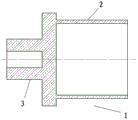
图1是根据本发明实施例的用于射频连接器的硬质塑料材质防护帽的截面图。1 is a cross-sectional view of a hard plastic protective cap for a radio frequency connector according to an embodiment of the present invention.
图2是根据本发明实施例的用于射频连接器的金属材质防护帽的截面图。2 is a cross-sectional view of a metal protective cap for a radio frequency connector according to an embodiment of the present invention.
图3是4.1/9.5型和4.3/10.0型射频连接器的示意图,其中,图3A是4.1/9.5型射频连接器的插座连接件的示意图,图3B是4.1/9.5型射频连接器的插头连接件的示意图,图3C是4.3/10.0型射频连接器的插座连接件的示意图,并且图3D是4.3/10.0型射频连接器的插头连接件的示意图。Fig. 3 is a schematic diagram of 4.1/9.5 type and 4.3/10.0 type RF connectors, wherein, Fig. 3A is a schematic diagram of a socket connector of a 4.1/9.5 type RF connector, and Fig. 3B is a plug connection of a 4.1/9.5 type RF connector FIG. 3C is a schematic diagram of a receptacle connection of a 4.3/10.0 type RF connector, and FIG. 3D is a schematic diagram of a plug connection of a 4.3/10.0 type RF connector.
图4是防护帽用于保护4.3/10.0型射频连接器的插座连接件的截面图。Figure 4 is a cross-sectional view of a protective cap used to protect a receptacle connector of a 4.3/10.0 type RF connector.
图5是防护帽与4.1/9.5型射频连接器的插头连接件相配合时的截面图。Figure 5 is a cross-sectional view of the protective cap mating with the plug connector of the 4.1/9.5 type RF connector.
图6是防护帽与4.3/10.0型射频连接器的插头连接件相配合时的截面图。Figure 6 is a cross-sectional view of the protective cap mated with the plug connector of the 4.3/10.0 type RF connector.
具体实施方式Detailed ways
以下参照附图介绍根据本发明用于射频连接器的具有检验功能的防护帽的实施例。说明内容和附图实质上仅仅是示范性的,而并不是为了以任何方式限制所附权利要求的保护范围。The following describes an embodiment of the protective cap with inspection function for a radio frequency connector according to the present invention with reference to the accompanying drawings. The description and drawings are merely exemplary in nature and are not intended to limit the scope of protection of the appended claims in any way.
在以下对本发明优选实施例的描述中,防护帽被用于检验4.1/9.5型和4.3/10.0型射频连接器的适配性。然而,应该理解,这仅仅是示例性的。实际上,根据本发明的用于射频连接器的防护帽能够用于检验和区分任意两种外形相似但内部装配构造不同的射频连接器。In the following description of the preferred embodiment of the present invention, the protective cap is used to verify the fit of the 4.1/9.5 and 4.3/10.0 RF connectors. However, it should be understood that this is merely exemplary. In fact, the protective cap for a radio frequency connector according to the present invention can be used to inspect and distinguish any two radio frequency connectors that are similar in appearance but different in internal assembly configuration.
如图1和图2所示,根据本发明用于射频连接器的具有检验功能的防护帽1包括:防护部2,所述防护部构造成用以与4.3/10.0型射频连接器的插座连接件相接合;检验部3,所述检验部构造成只能被4.3/10.0型射频连接器的插头连接件插入,由此,所述检验部能够用于检验和判定插头连接件是否为4.3/10.0型射频连接器的插头连接件。As shown in FIGS. 1 and 2 , a
当在天线上安装4.3/10.0型射频连接器时,所安装的射频连接器的端口是4.3/10.0型插座连接件,其外部螺纹采用标准的M20×1.0的普通螺纹。本发明的防护帽1的防护部2包含空心圆柱体区域,该空心圆柱体区域的尺寸构造成适配4.3/10.0型射频连接器的插座连接件的M20×1.0标准外螺纹。防护帽1的检验部3包括同轴的空心圆柱体区域,检验部3的空心圆柱体区域的尺寸构造成与4.3/10.0型射频连接器的插头连接件的尺寸相匹配。具体地,检验部3的空心圆柱体的长度为10.0mm,外径为11.30mm,内孔直径为4.5mm。When a 4.3/10.0 type RF connector is installed on the antenna, the port of the installed RF connector is a 4.3/10.0 type socket connector, and its external thread adopts a standard M20×1.0 common thread. The
防护帽1可以采用硬质塑料例如PE或者金属例如铜或铝材料制成。如图1所示,当防护帽1的材质为硬质塑料时,防护部2的圆柱形空心端内孔为平滑的圆柱,内孔直径略小于M20×1.0标准外螺纹直径,从而能够以紧配合直接套装在4.3/10.0型射频连接器的插座连接件上。如图2所示,当防护帽1的材质为金属材质时,防护部2的圆柱形空心端内孔为标准的M20×1.0普通内螺纹,能够直接与4.3/10.0型射频连接器的插座连接件的外螺纹相配合。The
图3是4.1/9.5型和4.3/10.0型射频连接器的示意图,其中,图3A是4.1/9.5型射频连接器的插座连接件4的示意图,图3B是4.1/9.5型射频连接器的插头连接件5的示意图,图3C是4.3/10.0型射频连接器的插座连接件6的示意图,并且图3D是4.3/10.0型射频连接器的插头连接件7的示意图。由图3A和图3C可知,4.1/9.5型射频连接器的插座连接件4与4.3/10.0型射频连接器的插座连接件6在外形上很容易区分,典型的区别在于4.3/10.0型射频连接器的插座连接件6有一个内开槽部分;而两种型号的插头连接件5和7在外形上用肉眼很难加以区分,基本一致。Figure 3 is a schematic diagram of the 4.1/9.5 type and 4.3/10.0 type RF connectors, wherein Figure 3A is a schematic diagram of the
在实践中能够发现,4.1/9.5型射频连接器的插座连接件4只可以配合4.1/9.5型插头连接件5,而4.3/10.0型插座连接件6不但可以配合4.3/10.0型插头连接件7,也可以与4.1/9.5型插头连接件5匹配,但是在与4.1/9.5型插头连接件5匹配后却会造成4.3/10.0型插座连接件6的内开槽部分的损坏。In practice, it can be found that the
根据本发明用于射频连接器的具有检验功能的防护帽1能够解决该问题。如图5所示,当防护帽1与4.1/9.5型插头连接件5配合时,由于4.1/9.5型插头连接件5的头部尺寸小于防护帽1的尺寸,头部无法进入防护帽1,因此可以判定不适配。如图6所示,当防护帽1与4.3/10.0型插头连接件7配合时,由于4.3/10.0型插头连接件7的头部尺寸与防护帽1的尺寸构造成使得头部刚好可以进入防护帽1,因此可以判定适配。The
防护帽1的使用方法具体地包括以下步骤:如图4所示,天线出厂时,将防护帽1安装在天线端的4.3/10.0型射频连接器的插座连接件6上。在安装天线时,如果安装人员无法判定所持有的插头连接件属于哪一种射频连接器,则可以利用防护帽1进行匹配判定,判定方法如下:The use method of the
A.当所持有的插头连接件无法插入防护帽1的检验部3时,则所持有的插头连接件为4.1/9.5型射频连接器的插头连接件5;A. When the held plug connector cannot be inserted into the
B.当所持有的插头连接件可以插入防护帽1的检验部3时,则所持有的插头连接件为4.3/10.0型射频连接器的插头连接件7。B. When the held plug connector can be inserted into the
当判定为4.3/10.0型射频连接器的插头连接件7之后,即可拿掉防护帽1,继续完成天线的安装。When it is determined that it is the
根据本发明的上述实施例用于射频连接器的具有检验功能的防护帽1可以为安装施工人员提供针对4.3/10.0型连接器的快速有效的检验辨别工具,从而避免错误的匹配而导致的产品损坏,具有实际有效的现实意义。According to the above-mentioned embodiment of the present invention, the
尽管已经参照某些实施例公开了本发明,但是在不背离本发明的范围和范畴的前提下,可以对所述的实施例进行多种变型和修改。因此,应该理解本发明并不局限于所阐述的实施例,其保护范围应当由所附权利要求的内容及其等价的结构和方案限定。Although the present invention has been disclosed with reference to certain embodiments, various changes and modifications of the described embodiments can be made without departing from the scope and scope of the invention. Therefore, it should be understood that the present invention is not limited to the described embodiments, but that the scope of protection should be defined by the content of the appended claims and their equivalent structures and arrangements.
Claims (10)
Priority Applications (3)
| Application Number | Priority Date | Filing Date | Title |
|---|---|---|---|
| CN201510345368.6A CN106329227B (en) | 2015-06-19 | 2015-06-19 | Protective cap for radio frequency connector and method of use thereof |
| US15/184,600 US9667018B2 (en) | 2015-06-19 | 2016-06-16 | Protective cap for radio-frequency connector and application method of protective cap |
| PCT/US2016/037824 WO2016205483A1 (en) | 2015-06-19 | 2016-06-16 | Protective cap for radio-frequency connector and application method of protective cap |
Applications Claiming Priority (1)
| Application Number | Priority Date | Filing Date | Title |
|---|---|---|---|
| CN201510345368.6A CN106329227B (en) | 2015-06-19 | 2015-06-19 | Protective cap for radio frequency connector and method of use thereof |
Publications (2)
| Publication Number | Publication Date |
|---|---|
| CN106329227A CN106329227A (en) | 2017-01-11 |
| CN106329227B true CN106329227B (en) | 2020-09-15 |
Family
ID=57546333
Family Applications (1)
| Application Number | Title | Priority Date | Filing Date |
|---|---|---|---|
| CN201510345368.6A Expired - Fee Related CN106329227B (en) | 2015-06-19 | 2015-06-19 | Protective cap for radio frequency connector and method of use thereof |
Country Status (3)
| Country | Link |
|---|---|
| US (1) | US9667018B2 (en) |
| CN (1) | CN106329227B (en) |
| WO (1) | WO2016205483A1 (en) |
Families Citing this family (6)
| Publication number | Priority date | Publication date | Assignee | Title |
|---|---|---|---|---|
| CN113140930A (en) * | 2015-06-30 | 2021-07-20 | 康普技术有限责任公司 | Guard for radio frequency connector |
| USD848370S1 (en) * | 2017-03-15 | 2019-05-14 | Gigalane Co., Ltd. | Radio frequency connector |
| US10116078B1 (en) * | 2017-08-01 | 2018-10-30 | Delphi Technologies, Inc. | High current compression blade connection system |
| USD908641S1 (en) * | 2017-11-30 | 2021-01-26 | Roos Instruments, Inc. | Blind mate waveguide flange |
| CN110661134B (en) * | 2019-09-30 | 2021-03-23 | 中航光电科技股份有限公司 | Dust cap assembly and connector assembly using the same |
| USD946534S1 (en) * | 2019-10-25 | 2022-03-22 | Applied Materials, Inc. | Radio frequency conduit |
Citations (6)
| Publication number | Priority date | Publication date | Assignee | Title |
|---|---|---|---|---|
| US6309246B1 (en) * | 2000-08-31 | 2001-10-30 | Telxon Corporation | Protective RF terminator cap |
| EP1172671A1 (en) * | 2000-07-03 | 2002-01-16 | Yazaki Corporation | Protection cap for optical connector |
| US20070099456A1 (en) * | 2005-10-28 | 2007-05-03 | Shawn Chawgo | Protective cap for coaxial cable port terminator |
| CN201674066U (en) * | 2010-02-11 | 2010-12-15 | 托普思电子股份有限公司 | Connector assembly |
| CN202817296U (en) * | 2012-10-09 | 2013-03-20 | 深圳市友讯达科技发展有限公司 | Protection sheath for SMA radio frequency connector |
| CN103887624A (en) * | 2014-04-18 | 2014-06-25 | 苏州瑞可达连接系统有限公司 | Anti-pluggable and anti-dislocation radio frequency coaxial board to board connector |
Family Cites Families (19)
| Publication number | Priority date | Publication date | Assignee | Title |
|---|---|---|---|---|
| US4258970A (en) * | 1979-03-05 | 1981-03-31 | The Bendix Corporation | Electrical cable and molded protection cap assembly |
| US5435736A (en) * | 1993-09-07 | 1995-07-25 | Raychem Corporation | Coaxial cable connection protection system for unused connection port |
| US9239441B2 (en) * | 2000-05-26 | 2016-01-19 | Corning Cable Systems Llc | Fiber optic drop cables and preconnectorized assemblies having toning portions |
| US7113679B2 (en) * | 2000-05-26 | 2006-09-26 | Corning Cable Systems, Llc | Fiber optic drop cables and preconnectorized assemblies having toning portions |
| US6922888B2 (en) * | 2001-05-25 | 2005-08-02 | Speed Systems Inc. | Loadbreak elbow pulling tool apparatus |
| US7270487B2 (en) * | 2004-04-30 | 2007-09-18 | Corning Cable Systems Llc | Field installable optical fiber connector |
| US7146090B2 (en) * | 2004-06-17 | 2006-12-05 | Corning Cable Systems Llc | Fiber optic cable and plug assembly |
| CN201048206Y (en) * | 2007-06-26 | 2008-04-16 | 罗若晖 | Electric energy metering anti-error connecting terminal box |
| US7802472B1 (en) * | 2007-08-21 | 2010-09-28 | Fluke Corporation | Ruggedized sensor probe |
| US7696850B2 (en) | 2007-11-08 | 2010-04-13 | Triasx Pty Ltd. | Apparatus for applying a load |
| US7744286B2 (en) * | 2007-12-11 | 2010-06-29 | Adc Telecommunications, Inc. | Hardened fiber optic connection system with multiple configurations |
| US7857647B2 (en) * | 2008-04-09 | 2010-12-28 | Hubbell Incorporated | Weather resistant electrical connector |
| US7798829B2 (en) * | 2008-04-11 | 2010-09-21 | Thomas & Betts International, Inc. | Basic insulating plug and method of manufacture |
| US9069026B1 (en) * | 2009-11-12 | 2015-06-30 | Eric G. Rutkowsky | Diagnostic tool for trailer lights |
| EP2529450A4 (en) * | 2010-01-25 | 2014-10-22 | Enphase Energy Inc | Method and apparatus for interconnecting distributed power sources |
| US7914306B1 (en) * | 2010-10-11 | 2011-03-29 | Donald A. Blackwell | Environmental protective covering for universal serial bus connectors |
| US20120315808A1 (en) | 2011-06-08 | 2012-12-13 | Izzy Industries Inc. | Dust cap with desiccant |
| CN203466361U (en) * | 2013-07-18 | 2014-03-05 | 鞠敏 | an electrical connector |
| US9490590B2 (en) * | 2015-02-05 | 2016-11-08 | Nokia Solutions And Networks Oy | Antenna connector sealing nut having a mechanical enclosure housing a radio frequency connector |
-
2015
- 2015-06-19 CN CN201510345368.6A patent/CN106329227B/en not_active Expired - Fee Related
-
2016
- 2016-06-16 US US15/184,600 patent/US9667018B2/en not_active Expired - Fee Related
- 2016-06-16 WO PCT/US2016/037824 patent/WO2016205483A1/en not_active Ceased
Patent Citations (6)
| Publication number | Priority date | Publication date | Assignee | Title |
|---|---|---|---|---|
| EP1172671A1 (en) * | 2000-07-03 | 2002-01-16 | Yazaki Corporation | Protection cap for optical connector |
| US6309246B1 (en) * | 2000-08-31 | 2001-10-30 | Telxon Corporation | Protective RF terminator cap |
| US20070099456A1 (en) * | 2005-10-28 | 2007-05-03 | Shawn Chawgo | Protective cap for coaxial cable port terminator |
| CN201674066U (en) * | 2010-02-11 | 2010-12-15 | 托普思电子股份有限公司 | Connector assembly |
| CN202817296U (en) * | 2012-10-09 | 2013-03-20 | 深圳市友讯达科技发展有限公司 | Protection sheath for SMA radio frequency connector |
| CN103887624A (en) * | 2014-04-18 | 2014-06-25 | 苏州瑞可达连接系统有限公司 | Anti-pluggable and anti-dislocation radio frequency coaxial board to board connector |
Also Published As
| Publication number | Publication date |
|---|---|
| US20160372883A1 (en) | 2016-12-22 |
| US9667018B2 (en) | 2017-05-30 |
| CN106329227A (en) | 2017-01-11 |
| WO2016205483A1 (en) | 2016-12-22 |
Similar Documents
| Publication | Publication Date | Title |
|---|---|---|
| CN106329227B (en) | Protective cap for radio frequency connector and method of use thereof | |
| CN108682988B (en) | Electromagnetic Compatibility Cable Locking Connector | |
| US20140322968A1 (en) | Coaxial cable connector with integral rfi protection and biasing ring | |
| CN105284015A (en) | Coaxial cable connector with integral RFI protection | |
| US10658794B2 (en) | Anti-misplug coaxial connector assembly | |
| WO2012054373A2 (en) | Dielectric sealing member and method of use thereof | |
| US20110217876A1 (en) | Electrical connector with sacrificial appendage | |
| US20140057490A1 (en) | Integrated compression connector | |
| CA2974660C (en) | Contacts with retractable drive pins | |
| US9531180B2 (en) | Waterproof cable assembly/connector | |
| US8574007B2 (en) | Electrical connector having a shielding adapter to radially compress a shielding ferrule onto a cable | |
| US20120214336A1 (en) | Electrical connector with sacrificial appendage | |
| CN102176585B (en) | Electric connector assembly | |
| WO2013083971A3 (en) | An electrical connector and method of assembly thereof | |
| US10326194B2 (en) | Antenna mount for electrical panel boards | |
| CN207705740U (en) | The sealing structure of micro-base station antenna cable outlet | |
| CN203377450U (en) | Circular electric connector | |
| CN204011849U (en) | A kind of adapter coaxial contact piece | |
| CA2846946C (en) | Electrical connector with sacrificial appendage | |
| US20150026976A1 (en) | Connector installation tool | |
| CN205752647U (en) | A kind of connector for radio-frequency coaxial cable inner wire | |
| KR102558018B1 (en) | Cavity-backed coupler with connector located in rear side | |
| CN204144474U (en) | A kind of coupling assembling of cable | |
| CN203492257U (en) | Interface grounded connector and electronic device with interface grounded connector | |
| CN110752468A (en) | A repairable cluster coaxial electrical connector |
Legal Events
| Date | Code | Title | Description |
|---|---|---|---|
| PB01 | Publication | ||
| PB01 | Publication | ||
| SE01 | Entry into force of request for substantive examination | ||
| SE01 | Entry into force of request for substantive examination | ||
| GR01 | Patent grant | ||
| GR01 | Patent grant | ||
| CF01 | Termination of patent right due to non-payment of annual fee |
Granted publication date: 20200915 |
|
| CF01 | Termination of patent right due to non-payment of annual fee |