CN106154471B - Production method of full-dry type big data photoelectric network cable and big data photoelectric network cable - Google Patents
Production method of full-dry type big data photoelectric network cable and big data photoelectric network cable Download PDFInfo
- Publication number
- CN106154471B CN106154471B CN201610786789.7A CN201610786789A CN106154471B CN 106154471 B CN106154471 B CN 106154471B CN 201610786789 A CN201610786789 A CN 201610786789A CN 106154471 B CN106154471 B CN 106154471B
- Authority
- CN
- China
- Prior art keywords
- cable
- sheath
- optical fiber
- die
- layer
- Prior art date
- Legal status (The legal status is an assumption and is not a legal conclusion. Google has not performed a legal analysis and makes no representation as to the accuracy of the status listed.)
- Active
Links
- 238000004519 manufacturing process Methods 0.000 title claims abstract description 15
- 239000013307 optical fiber Substances 0.000 claims abstract description 99
- 230000000903 blocking effect Effects 0.000 claims abstract description 40
- XLYOFNOQVPJJNP-UHFFFAOYSA-N water Substances O XLYOFNOQVPJJNP-UHFFFAOYSA-N 0.000 claims abstract description 40
- 230000003287 optical effect Effects 0.000 claims abstract description 33
- 239000000463 material Substances 0.000 claims abstract description 10
- 239000002184 metal Substances 0.000 claims abstract description 5
- 238000001125 extrusion Methods 0.000 claims description 46
- 239000003292 glue Substances 0.000 claims description 46
- 229910000831 Steel Inorganic materials 0.000 claims description 30
- 239000010959 steel Substances 0.000 claims description 30
- 239000011248 coating agent Substances 0.000 claims description 18
- 238000000576 coating method Methods 0.000 claims description 18
- 238000004804 winding Methods 0.000 claims description 18
- 238000003892 spreading Methods 0.000 claims description 17
- 238000003860 storage Methods 0.000 claims description 17
- 238000000034 method Methods 0.000 claims description 7
- 239000002390 adhesive tape Substances 0.000 claims description 5
- 238000004026 adhesive bonding Methods 0.000 claims description 4
- 238000005096 rolling process Methods 0.000 claims description 2
- 239000011159 matrix material Substances 0.000 claims 1
- 239000004677 Nylon Substances 0.000 abstract description 5
- 229920001778 nylon Polymers 0.000 abstract description 5
- 238000010276 construction Methods 0.000 abstract description 2
- 230000003014 reinforcing effect Effects 0.000 abstract description 2
- 241000257303 Hymenoptera Species 0.000 abstract 1
- 241000700159 Rattus Species 0.000 abstract 1
- 230000005611 electricity Effects 0.000 abstract 1
- 239000000853 adhesive Substances 0.000 description 6
- 230000001070 adhesive effect Effects 0.000 description 6
- 239000007788 liquid Substances 0.000 description 5
- 238000004891 communication Methods 0.000 description 3
- 238000010586 diagram Methods 0.000 description 3
- 229920002725 thermoplastic elastomer Polymers 0.000 description 3
- 238000005452 bending Methods 0.000 description 2
- 230000005540 biological transmission Effects 0.000 description 2
- 238000007598 dipping method Methods 0.000 description 2
- 230000000694 effects Effects 0.000 description 2
- 241000256602 Isoptera Species 0.000 description 1
- 241000699670 Mus sp. Species 0.000 description 1
- 241000283984 Rodentia Species 0.000 description 1
- 230000009286 beneficial effect Effects 0.000 description 1
- 230000007547 defect Effects 0.000 description 1
- 239000000835 fiber Substances 0.000 description 1
- 238000001746 injection moulding Methods 0.000 description 1
- 230000000149 penetrating effect Effects 0.000 description 1
- 238000002360 preparation method Methods 0.000 description 1
- 230000002787 reinforcement Effects 0.000 description 1
- 239000000243 solution Substances 0.000 description 1
- 238000003466 welding Methods 0.000 description 1
Images


Classifications
-
- G—PHYSICS
- G02—OPTICS
- G02B—OPTICAL ELEMENTS, SYSTEMS OR APPARATUS
- G02B6/00—Light guides; Structural details of arrangements comprising light guides and other optical elements, e.g. couplings
- G02B6/44—Mechanical structures for providing tensile strength and external protection for fibres, e.g. optical transmission cables
- G02B6/4401—Optical cables
- G02B6/4429—Means specially adapted for strengthening or protecting the cables
- G02B6/443—Protective covering
-
- G—PHYSICS
- G02—OPTICS
- G02B—OPTICAL ELEMENTS, SYSTEMS OR APPARATUS
- G02B6/00—Light guides; Structural details of arrangements comprising light guides and other optical elements, e.g. couplings
- G02B6/44—Mechanical structures for providing tensile strength and external protection for fibres, e.g. optical transmission cables
- G02B6/4401—Optical cables
- G02B6/4429—Means specially adapted for strengthening or protecting the cables
- G02B6/44384—Means specially adapted for strengthening or protecting the cables the means comprising water blocking or hydrophobic materials
-
- H—ELECTRICITY
- H01—ELECTRIC ELEMENTS
- H01B—CABLES; CONDUCTORS; INSULATORS; SELECTION OF MATERIALS FOR THEIR CONDUCTIVE, INSULATING OR DIELECTRIC PROPERTIES
- H01B13/00—Apparatus or processes specially adapted for manufacturing conductors or cables
-
- H—ELECTRICITY
- H01—ELECTRIC ELEMENTS
- H01B—CABLES; CONDUCTORS; INSULATORS; SELECTION OF MATERIALS FOR THEIR CONDUCTIVE, INSULATING OR DIELECTRIC PROPERTIES
- H01B7/00—Insulated conductors or cables characterised by their form
- H01B7/0045—Cable-harnesses
-
- H—ELECTRICITY
- H01—ELECTRIC ELEMENTS
- H01B—CABLES; CONDUCTORS; INSULATORS; SELECTION OF MATERIALS FOR THEIR CONDUCTIVE, INSULATING OR DIELECTRIC PROPERTIES
- H01B7/00—Insulated conductors or cables characterised by their form
- H01B7/17—Protection against damage caused by external factors, e.g. sheaths or armouring
- H01B7/18—Protection against damage caused by wear, mechanical force or pressure; Sheaths; Armouring
- H01B7/187—Sheaths comprising extruded non-metallic layers
-
- H—ELECTRICITY
- H01—ELECTRIC ELEMENTS
- H01B—CABLES; CONDUCTORS; INSULATORS; SELECTION OF MATERIALS FOR THEIR CONDUCTIVE, INSULATING OR DIELECTRIC PROPERTIES
- H01B7/00—Insulated conductors or cables characterised by their form
- H01B7/17—Protection against damage caused by external factors, e.g. sheaths or armouring
- H01B7/28—Protection against damage caused by moisture, corrosion, chemical attack or weather
- H01B7/282—Preventing penetration of fluid, e.g. water or humidity, into conductor or cable
- H01B7/2825—Preventing penetration of fluid, e.g. water or humidity, into conductor or cable using a water impermeable sheath
-
- H—ELECTRICITY
- H01—ELECTRIC ELEMENTS
- H01B—CABLES; CONDUCTORS; INSULATORS; SELECTION OF MATERIALS FOR THEIR CONDUCTIVE, INSULATING OR DIELECTRIC PROPERTIES
- H01B7/00—Insulated conductors or cables characterised by their form
- H01B7/17—Protection against damage caused by external factors, e.g. sheaths or armouring
- H01B7/28—Protection against damage caused by moisture, corrosion, chemical attack or weather
- H01B7/282—Preventing penetration of fluid, e.g. water or humidity, into conductor or cable
- H01B7/285—Preventing penetration of fluid, e.g. water or humidity, into conductor or cable by completely or partially filling interstices in the cable
-
- Y—GENERAL TAGGING OF NEW TECHNOLOGICAL DEVELOPMENTS; GENERAL TAGGING OF CROSS-SECTIONAL TECHNOLOGIES SPANNING OVER SEVERAL SECTIONS OF THE IPC; TECHNICAL SUBJECTS COVERED BY FORMER USPC CROSS-REFERENCE ART COLLECTIONS [XRACs] AND DIGESTS
- Y02—TECHNOLOGIES OR APPLICATIONS FOR MITIGATION OR ADAPTATION AGAINST CLIMATE CHANGE
- Y02A—TECHNOLOGIES FOR ADAPTATION TO CLIMATE CHANGE
- Y02A30/00—Adapting or protecting infrastructure or their operation
Landscapes
- Physics & Mathematics (AREA)
- General Physics & Mathematics (AREA)
- Optics & Photonics (AREA)
- Engineering & Computer Science (AREA)
- Manufacturing & Machinery (AREA)
- Manufacturing Of Electric Cables (AREA)
- Light Guides In General And Applications Therefor (AREA)
Abstract
The invention relates to a production method of a full-dry type big data photoelectric network cable and the big data photoelectric network cable. The big data photoelectric network cable comprises an electric wire, a television line, a network cable, an optical cable formed by a plurality of coiled optical fiber belts, water blocking materials filled among the television line, the network cable and the optical cable, a first-layer sheath, a water blocking belt, a metal belt, a second-layer sheath and a three-layer sheath which are coated on the television line, the network cable, the optical cable and the water blocking materials from inside to outside, wherein the electric wire is embedded in the second-layer sheath. The advantages are that: the cable utilization rate is high; the prospective is good; the diameter of the optical fiber ribbon unit can be reduced, a plurality of optical fiber ribbon units are convenient to weld, and the construction efficiency is high; the electric wire is used as a reinforcing piece, so that the electric wire can conduct electricity, the tensile property of the optical cable can be improved, and the third layer of sheath of the modified nylon can prevent rats and ants.
Description
Technical Field
The invention relates to a cable, in particular to a production method of a full-dry type big data photoelectric network cable and the big data photoelectric network cable.
Background
With the development of science and society, people have higher requirements on communication, and network wires and optical fiber wires are required to be laid in addition to television wires on which cable televisions are laid in general families, so that people often see television wires, network cables and optical cables which are laid in disorder in communities, the sightseeing is affected and the cables are easy to damage, and meanwhile, if the prior cable layout is not provided in advance, for example, the optical cables are not provided, and then the optical cables are required to be laid, and the slotting is required to be drilled again, so that the prior cable layout is not prospective. In addition, the ribbons in existing fiber optic cables are stacked such that the diameter of the cable containing a number of optical fibers is relatively large.
Disclosure of Invention
The invention aims to overcome the defects of the prior art and provide an all-dry large-data photoelectric network cable which can be used for simultaneously laying wires, television lines, network cables and optical cables and has relatively small cable diameter, and a corresponding production method thereof.
In order to achieve the purpose, the production method of the full-dry big data photoelectric network cable comprises the following steps:
a ribbon combining mode unit is used for enabling a plurality of parallel optical fibers to pass through the ribbon combining mode unit, the ribbon combining mode unit is used for gluing the optical fibers at equal intervals, and adjacent optical fibers are connected with each other through gluing to form an optical fiber ribbon;
winding the optical fiber ribbon to form a spiral section through a winding die, wherein the wound optical fiber ribbon is wound through a yarn drum and is bundled by yarns to form a wound optical fiber ribbon;
the manufacturing method of the optical cable comprises the steps of manufacturing the optical cable, introducing a plurality of coiled optical fiber ribbons and water-blocking yarns filled between the coiled optical fiber ribbons into an extruder, and enabling the coiled optical fibers and the water-blocking yarns to be coated in a sleeve formed by extrusion molding of the extruder to form the optical cable;
combining the cables, introducing a network cable, a television line, the optical cable and water-blocking yarns filled between the cables into a first extrusion molding die, so that the cables are combined and coated in a first layer of sheath formed by extrusion molding of the first extrusion molding die to form a layer of sheath combined cable;
coating a water blocking belt and a steel belt, arranging a steel belt die on the running path of a layer of sheath combined cable, enabling the water blocking belt and the steel belt to pass through the steel belt die simultaneously with the layer of sheath combined cable, enabling the water blocking belt to be positioned between the layer of sheath combined cable and the steel belt, and enabling the water blocking belt and the steel belt to be coated outside the layer of sheath combined cable from inside to outside by the steel belt die to form the water blocking combined cable;
coating a second-layer sheath, arranging a second extrusion molding die on the running path of the water-blocking combined cable, enabling the water-blocking combined cable and two wires symmetrically arranged on two sides of the water-blocking combined cable to pass through the second extrusion molding die, enabling the second-layer sheath formed by extrusion molding of the second extrusion molding die to be coated on the outer side of the water-blocking combined cable, and enabling the two wires to be symmetrically embedded in the second-layer sheath to form the two-layer sheath combined cable;
and coating three layers of sheaths, wherein a third extrusion molding die is arranged on the running path of the two layers of sheath combined cables, and the two layers of sheath combined cables pass through the third extrusion molding die, so that the third layer of sheaths formed by extrusion molding of the third extrusion molding die are coated on the outer sides of the two layers of sheath combined cables, and the full-dry big data photoelectric network cable is formed.
The ribbon-combining die is glued on the plurality of parallel optical fibers at equal intervals of 6-10 cm.
The parallel-belt die unit comprises a parallel-belt die, a glue spreading brush and a glue storage groove, wherein the parallel-belt die is arranged on an optical fiber operation line and is provided with a slotted hole matched with the parallel optical fibers, the upper end of the slotted hole is provided with a glue spreading hole communicated with the slotted hole, the glue storage groove is arranged on one side of the parallel-belt die, and the glue spreading brush is arranged above the parallel-belt die in a sliding manner and slides along the glue spreading hole and stays in the glue storage groove.
The winding die is rolled into a cone shape, and a spiral convex rib is arranged on the inner conical surface of the inner wall of the cone.
The steel belt die comprises a conical tube and a circular tube, wherein the circular tube is connected to the small-diameter end of the conical tube, and the inner cavity wall of the conical tube is provided with a guide surface for overlapping at a rolling joint.
The second extrusion molding die comprises an inner die and an outer die, wherein the inner die is provided with a cavity with an inner conical surface, the front end of the outer die is conical, a coaxial lead-in hole and a forming hole are formed in the center from back to front, and wire lead-in holes for embedding wires are respectively formed in two symmetrical sides of the forming hole.
To achieve the object, the all-dry big data optical-electrical network cable includes: the cable comprises an electric wire, a television line, a network cable, an optical cable formed by a plurality of coiled optical fiber ribbons, a water blocking material filled among the television line, the network cable and the optical cable, and a first-layer sheath, a water blocking belt, a metal belt, a second-layer sheath and a three-layer sheath which are coated on the television line, the network cable, the optical cable and the water blocking material from inside to outside, wherein the electric wire is embedded in the second-layer sheath.
The coiled optical fiber ribbon is formed by coiling 2-12 optical fiber ribbons which are connected in parallel.
The optical cable comprises a plurality of coiled optical fiber ribbons, water blocking yarns filled between the coiled optical fiber ribbons and a pipe sleeve coated on the outer sides of the coiled optical fiber ribbons and the water blocking yarns.
The optical fiber belts connected in parallel are formed by coating adhesive tapes with the width of 1.0-5.0 mmd on one sides of the optical fibers in parallel at equal intervals, and the adhesive tapes are not parallel to the arrangement direction of the optical fibers.
The thicknesses of the first sheath, the water blocking belt, the metal belt, the second sheath and the third sheath are as follows: 0.5-1.0, 0.1-0.3, 0.2-0.3, 2.0-3.5 and 0.3-0.6 mm, the diameter of the electric wire is 0.5-2.0 mm.
The invention has the beneficial effects that:
(1) The signals can be synchronously transmitted, so that the utilization rate of the cable is increased;
(2) The communication lines are rich, can be accessed in time along with new communication requirements, and have good prospective
(3) The optical fiber ribbon is a coiled optical fiber ribbon, so that the diameter of an optical fiber ribbon unit can be reduced, the effect of increasing the density of optical fibers is achieved, the optical fiber ribbon is tiled during welding, a plurality of optical fibers can be welded simultaneously, and the construction efficiency is improved.
(4) The electric wires are distributed in the second layer of sheath in parallel, so that the tensile property of the optical cable can be improved as a reinforcing piece, and a better insulating effect can be achieved.
(5) The third layer of sheath adopts modified nylon, increases the ability of preventing rodents such as mice from biting, and can also prevent termite's efficiency.
Drawings
Fig. 1 is a schematic structural diagram of a big data optical-electrical network cable of the present invention.
FIG. 2 is a schematic illustration of a coiled optical fiber ribbon manufacturing process.
Fig. 3 is a schematic view of the structure with the die unit.
Fig. 4 is a schematic structural view of the winding mold.
Fig. 5 is an axial sectional view of the winding die shown in fig. 4.
Fig. 6 is a schematic diagram of a cable manufacturing process.
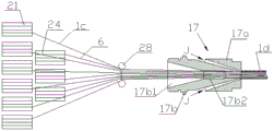
Fig. 7 is a schematic diagram of the photovoltaic cable preparation process of the present invention.
Fig. 8 is a schematic structural view of a steel strip mold.
Fig. 9 is an axial cross-sectional view of the steel strip die shown in fig. 8.
FIG. 10 is a schematic view of the internal mold structure of a third extrusion mold.
FIG. 11 is a schematic of the external mold structure of a third extrusion mold.
Detailed Description
Fig. 1 shows a big data optical-electrical network cable 2d manufactured by the method of the present invention, which comprises an electric wire 5, a television wire 3, a network cable 4, an optical cable formed by winding a plurality of optical fiber tapes, a water-blocking material filled between the television wire 3, the network cable 4 and the optical cable 1c, and a layer of sheath 31, a water-blocking tape 7, a metal tape, a two-layer sheath 32 and a three-layer sheath 33 which are coated on the television wire 3, the network cable 4, the optical cable 1c from inside to outside, wherein the television wire 3 is embedded in the two-layer sheath 32. The electro-optical network cable 2d will be produced by the method described below.
As shown in fig. 2, 12 optical fibers 1 are paid out by a corresponding optical fiber paying-out machine 20 and run forward at a speed of 60 to 120 m/s, a ribbon-forming die unit 10 is provided on a line on which the optical fibers run, a plurality of parallel optical fibers 1 pass through the ribbon-forming die 101, and the glue-spreading frequency of the ribbon-forming die unit 10 is controlled to equally space glue the passing parallel optical fibers 1, so that adjacent optical fibers are connected to each other by the glue-spreading to form an optical fiber ribbon 1a. A winding die 11 and a yarn tube 12 are provided in this order on a line along which the optical fiber ribbon 1a runs forward, the optical fiber ribbon 1a is wound into a spiral section by the winding die 11, and the wound optical fiber ribbon 1b is wound on the optical fiber ribbon winding drum 21 by the yarn tube 12 with yarn wound thereon to form a wound optical fiber ribbon 1c.
The parallel-belt die unit comprises a parallel-belt die, a glue spreading brush and a glue storage groove, wherein the parallel-belt die is arranged on an optical fiber operation line and is provided with a slotted hole matched with the parallel optical fibers, the upper end of the slotted hole is provided with a glue spreading hole communicated with the slotted hole, the glue storage groove is arranged on one side of the parallel-belt die, and the glue spreading brush is arranged above the parallel-belt die in a sliding manner and slides along the glue spreading hole and stays in the glue storage groove.
The above-mentioned tape-combining die unit 10 is mainly composed of a tape-combining die 101, a glue spreading brush 102 and a glue storage tank 103, the glue storage tank 103 is arranged on one side of the tape-combining die 101, and the glue spreading brush 102 is slidably arranged above the tape-combining die 101.
As shown in fig. 3, the glue brush 102 in the tape-combining die unit 10 is slidably disposed above the tape-combining die 101 by a bracket 105, a driving screw 107 and a guide rod 106, and has the following specific structure: the ribbon-drawing die 101 is a basic rectangular body, the die-drawing die is provided with a slotted hole 1011 which is matched with the outline dimension of the 12 parallel optical fibers, the 12 optical fibers 1 are arranged in parallel by the slotted hole 1011, the upper end of the slotted hole 1011 is provided with a glue-coating hole 1012 which is communicated with the slotted hole, and the glue-coating brush 102 coats the corresponding optical fibers 1 at the position of the slotted hole 1011, so that narrower adhesive-coated tapes 1e are formed in the ribbon-drawing direction of the optical fibers 1, the adhesive-coated tapes 1e are distributed at equal intervals, and the separate optical fibers are connected with each other to form the optical fiber ribbon 1a. The glue storage groove 103 is arranged on one side of the tape combining die 101, the bracket 105 is respectively fixed on the tape combining die 101 and the glue storage groove 103, the transmission screw 107 is rotationally connected to the bracket 105 and is connected with the stepping motor 104, the two guide rods 106 are symmetrically arranged on two sides of the transmission screw 104, and two ends of the guide rods are connected to the bracket 105; according to the running speed of the optical fiber, the stepping motor works according to a set beat so that the glue coating brush 102 uniformly coats the optical fiber in the parallel belt mold 101 according to a set distance, for example, the glue coating is performed according to a set 6cm interval, or 8cm interval, or 10cm interval, so as to form an inclined adhesive coating tape 1e, and the adhesive coating tape 1e is not parallel to the arrangement direction of the optical fiber; the lower part of the glue spreading brush 102 is provided with bristles 1022, and the upper part is provided with screw holes and guide holes respectively matched with the screw rods and the guide rods 106; the glue storage tank 103 is provided with an inclined plane 1031 on the side adjacent to the tape combining die 101, the upper end of the inclined plane 1031 is basically flush with the upper end of the optical fiber, the liquid level of the stored glue solution in the glue storage tank 103 is slightly lower than the upper end of the inclined plane 1031 and is kept to be horizontal by a liquid level sensor (not shown), the lower ends of the bristles are slightly lower than the liquid level, the glue dipping amount is ensured to be basically the same each time, and when the glue dipping amount is lower than the liquid level, the glue is replenished through a liquid inlet. The motor 104 drives the screw 107 to rotate, and the screw hole on the glue brush 102 is meshed with the screw 107 to enable the screw hole to axially move along the guide rod 106, if the starting position of the glue brush 102 is located in the glue storage groove 103 (the position of the glue brush 102 is shown by a dotted line in fig. 3), the glue brush 102 slides to the glue coating hole 1012 on the tape die 101 easily through an inclined plane, and glue coating through a repeated stroke stays in the glue storage groove.
The winding die 11 and the yarn tube 12 are arranged on the path of the optical fiber ribbon 1a, the flat optical fiber ribbon 1a is formed by connecting optical fibers 1 by the adhesive tape 1e which is arranged in a sparse way (with a mutual interval of 6-10 cm) and is arranged obliquely (with an adhesive coating width of 1.0-5.0 mm), the adhesive coating surface is used as an inner side surface bending surface during bending, and is easy to bend, when the optical fiber ribbon passes through the winding die, the optical fiber ribbon is wound into a spiral section, the yarn tube 12 is connected on the optical fiber ribbon 1b which is spirally wound in a penetrating way, one end of the yarn on the yarn tube 12 is connected with the optical fiber ribbon, and the yarn is continuously wound on the wound optical fiber ribbon 1b along with the forward running of the optical fiber ribbon, so that the spiral winding is prevented from loosening, and the wound optical fiber ribbon 1c is wound on the winding disc.
As shown in fig. 4 and 5, the winding mold 11 has a tapered cylindrical shape, and a spiral rib 111 is provided on an inner tapered surface of an inner wall of the cylindrical shape, and the spiral rib 111 drives the flat optical fiber ribbon 1a to wind by abutting against one side edge thereof, thereby forming a winding optical fiber ribbon 1c.
As shown in fig. 6, a plurality of the wound optical fiber ribbons 1c and water blocking yarns 6 are introduced into a first extrusion die 17, and gaps between the wound optical fiber ribbons are filled with the water blocking yarns 6 of 0.1 to 0.3mm, see fig. 1. The first extrusion die 17 is composed of an inner die 17b and an outer die 17a, the inner die 17b is provided with a cavity of an inner conical surface, the front end of the outer die 17a is conical, and an introducing hole 17b1 and a forming hole 17b2 for introducing the wound optical fiber ribbon 1c and the water blocking yarn 6 are provided in the center. The front end of the outer mold 17a is inserted into the inner conical surface of the inner mold 17b to form a conical ring surface cavity J, and the cavity J is vacuumized before injection molding. The PE or thermoplastic elastomer material for forming the first layer of jacket 31 is introduced into the mold through the cavity J, extruded from the front end of the cavity J under extrusion pressure and pulled forward by advancing the wound optical fiber ribbon 1c and the water blocking yarn 6 to form the jacket 30 having a wall thickness of 0.5 to 1.0mm, and the wound optical fiber and the water blocking yarn are wrapped in the jacket, thereby forming the optical cable 1d. Because the section of the optical fiber ribbon placed in the optical cable is basically circular, the space utilization rate is greatly increased, and the outer diameter of the optical cable wound with the optical fiber ribbon is 6.2mm, such as a flat optical fiber ribbon, and the optical cable with 6.2mm can only be provided with 96 cores.
Referring to fig. 7, the cable 1d wound on the wire reel 25 and the television wire 3 wound on the wire reel 22, the network cable 4 wound on the wire reel 23, and the water blocking yarn 6 wound on the wire reel 24 are respectively introduced into the second extrusion mold 13 through the corresponding wire feeding rollers 28 (the principle of which is the same as that of the first extrusion mold 17 and will not be repeated), thereby forming a first sheath 31 with a wall thickness of 0.5-1.0 mm covering the outside of the network cable, television wire, optical cable, and water blocking yarn, and the first sheath is made of PE or thermoplastic elastomer material, so as to form a sheath combining cable.
A water blocking tape 7 coiled on a wire coil 26 and a steel tape 8 coiled on a wire coil 27 are arranged on one side of a layer of sheath combining cable 2 running forwards, a steel tape die 14 is arranged in the advancing direction of the layer of sheath combining cable 2, the water blocking tape 7, the steel tape 8 and the layer of sheath combining cable 2 are led into the steel tape die 14 together, the water blocking tape 7 is arranged between the layer of sheath combining cable 2 and the steel tape 8, the steel tape die 14 is used for blocking water and the steel tape running at the same speed, and the layer of sheath combining cable, the water blocking tape and the steel tape are simultaneously covered on the outer side of the layer of sheath combining cable from inside to outside through the steel tape die 14, so that the water blocking combining cable 2a is formed.
As shown in fig. 8 and 9, the steel band mold 14 comprises a conical tube and a round tube, the round tube is connected to the small diameter end of the conical tube, guide surfaces 141 and 142 are arranged in the inner cavity of the conical tube and are used for guiding the two sides of the 0.1-0.3 mm water blocking tape 7 and the 0.2-0.3 mm steel band 8 which are led from the large diameter end of the conical tube to overlap at the joint, and as shown in fig. 9, overlapping parts 7a and 8a are generated, when the water blocking tape 7 and the steel band 8 which are led to be rolled by the conical tube are pressed into the overlapping parts of the round tube, thereby forming the water blocking combination cable 2a.
With continued reference to fig. 7, a second extrusion mold 15 is disposed on the running path of the water-blocking combined cable, the water-blocking combined cable 2a and two wires 5 symmetrically disposed on both sides of the water-blocking combined cable (the two wires 5 are wound on corresponding reels 29 respectively) are simultaneously introduced into the second extrusion mold 15, the second extrusion mold 15 has a structure as shown in fig. 10 and 11, and is composed of an inner mold 15b and an outer mold 15a, similar to the structure of the first extrusion mold 17 in fig. 6, wherein the inner mold 15b is provided with a cavity with an inner conical surface, the front end of the outer mold 17a is tapered, an introduction hole 15b1 and a forming hole 15b2 are centrally disposed, and the wires 5 are led out from the introduction holes 15b3, respectively, on both sides of the forming hole 15b2, so that the two wires 5 are symmetrically embedded in a second sheath extrusion molded by the second extrusion mold, and the second sheath is wrapped outside the water-blocking combined cable 2b. The wire 5 thus functions as a reinforcement in addition to the wire. The two layers of sheaths are made of PE or thermoplastic elastomer, the wall thickness of the second layer of sheaths is 2.0-3.5 mm, the thickness of the wire 5 is generally 0.5-2.0, and the wall thickness of the sheath is larger than that of the wire 5, so that good insulativity of the wire is ensured.
A third extrusion die 16 is disposed on the traveling path of the two-layer jacketed merge cable 2b, and the third extrusion die 16 has substantially the same structure as the first extrusion die 17 and will not be described again. The two-layer sheath combining cable 2b passes through the third extrusion molding die 16, nylon materials are extruded by the third extrusion molding die 16 to form a nylon sheath, the two-layer sheath combining cable 2b is heated before extrusion molding, the bonding force between the nylon sheath and the second layer sheath is ensured, and the vacuumizing force of the cavity formed between the corresponding inner die and the corresponding outer die in the third extrusion molding die 16 is increased. The extrusion-molded third sheath 33 is firmly wrapped on the outer side of the two-layer sheath combined cable 2b to form the full-dry type big data photoelectric net cable 2d, and the wall thickness of the third sheath 33 is 0.3-0.6 mm.
Claims (8)
1. The production method of the full-dry type big data photoelectric network cable is characterized by comprising the following steps of:
a ribbon combining mode unit is used for enabling a plurality of parallel optical fibers to pass through the ribbon combining mode unit, the ribbon combining mode unit is used for gluing the optical fibers at equal intervals, and adjacent optical fibers are connected with each other through gluing to form an optical fiber ribbon;
the optical fiber ribbon is wound by a winding mould to form a spiral section, the wound optical fiber ribbon is wound by yarns to form a wound optical fiber ribbon through yarn winding of a yarn cylinder, the winding mould is wound into a cone shape, and a spiral convex rib is arranged on the inner conical surface of the inner wall of the cone;
the manufacturing method of the optical cable comprises the steps of manufacturing the optical cable, introducing a plurality of coiled optical fiber ribbons and water-blocking yarns filled between the coiled optical fiber ribbons into an extruder, and enabling the coiled optical fibers and the water-blocking yarns to be coated in a sleeve formed by extrusion molding of the extruder to form the optical cable;
combining the cables, introducing a network cable, a television line, the optical cable and water-blocking yarns filled between the cables into a first extrusion molding die, so that the cables are combined and coated in a first layer of sheath formed by extrusion molding of the first extrusion molding die to form a layer of sheath combined cable;
coating a water blocking belt and a steel belt, arranging a steel belt die on the running path of a layer of sheath combined cable, enabling the water blocking belt and the steel belt to pass through the steel belt die simultaneously with the layer of sheath combined cable, enabling the water blocking belt to be positioned between the layer of sheath combined cable and the steel belt, and enabling the water blocking belt and the steel belt to be coated outside the layer of sheath combined cable from inside to outside by the steel belt die to form the water blocking combined cable;
coating a second-layer sheath, arranging a second extrusion molding die on the running path of the water-blocking combined cable, enabling the water-blocking combined cable and two wires symmetrically arranged on two sides of the water-blocking combined cable to pass through the second extrusion molding die, enabling the second-layer sheath formed by extrusion molding of the second extrusion molding die to be coated on the outer side of the water-blocking combined cable, and enabling the two wires to be symmetrically embedded in the second-layer sheath to form the two-layer sheath combined cable;
and coating three layers of sheaths, wherein a third extrusion molding die is arranged on the running path of the two layers of sheath combined cables, and the two layers of sheath combined cables pass through the third extrusion molding die, so that the third layer of sheaths formed by extrusion molding of the third extrusion molding die are coated on the outer sides of the two layers of sheath combined cables, and the full-dry big data photoelectric network cable is formed.
2. The method of claim 1, wherein the ribbon matrix is applied to the plurality of parallel optical fibers at equal intervals of 6-10 cm.
3. The method for producing full-dry big data photoelectric network cables according to claim 1 or 2, wherein the combining die unit comprises a combining die, a glue spreading brush and a glue storage groove, the combining die is arranged on an optical fiber operation line and is provided with a slot hole matched with the plurality of parallel optical fibers, the upper end of the slot hole is provided with a glue spreading hole communicated with the slot hole, the glue storage groove is arranged on one side of the combining die, and the glue spreading brush is arranged above the combining die in a sliding manner, slides along the glue spreading hole and stays in the glue storage groove.
4. The method of claim 1, wherein the steel strip die comprises a conical tube and a round tube, the round tube is connected to the small diameter end of the conical tube, and the inner cavity wall of the conical tube is provided with a guide surface for overlapping at a rolling joint.
5. The method of claim 1, wherein the second extrusion mold comprises an inner mold and an outer mold, the inner mold is provided with a cavity with an inner conical surface, the front end of the outer mold is conical, the center of the outer mold is provided with a coaxial wire leading-in hole and a forming hole from back to front, and the symmetrical two sides of the forming hole are respectively provided with a wire leading-in hole for embedding a wire.
6. The method for producing full dry big data photoelectric network cable according to any one of claims 1-2 or 4-5, comprising an electric wire, a television line, a network cable, an optical cable formed by a plurality of coiled optical fiber ribbons coiled into a spiral section, a water blocking material filled between the television line, the network cable and the optical cable, and a sheath of the television line, the network cable, the optical cable, the water blocking material, a water blocking tape, a metal belt, a sheath of two layers and a sheath of three layers from inside to outside, wherein the electric wire is embedded in the sheath of two layers.
7. The method of claim 6, wherein the plurality of parallel optical fiber ribbons are formed by coating adhesive tapes with a width of 1.0-5.0 mmd on one side of the plurality of parallel optical fibers at equal intervals, and the adhesive tapes are not parallel to the arrangement direction of the optical fibers.
8. The method of claim 6, wherein the optical cable comprises a plurality of coiled optical fiber ribbons, water blocking yarns filled between the coiled optical fiber ribbons, and a jacket covering the coiled optical fiber ribbons and the water blocking yarns.
Priority Applications (1)
| Application Number | Priority Date | Filing Date | Title |
|---|---|---|---|
| CN201610786789.7A CN106154471B (en) | 2016-08-30 | 2016-08-30 | Production method of full-dry type big data photoelectric network cable and big data photoelectric network cable |
Applications Claiming Priority (1)
| Application Number | Priority Date | Filing Date | Title |
|---|---|---|---|
| CN201610786789.7A CN106154471B (en) | 2016-08-30 | 2016-08-30 | Production method of full-dry type big data photoelectric network cable and big data photoelectric network cable |
Publications (2)
| Publication Number | Publication Date |
|---|---|
| CN106154471A CN106154471A (en) | 2016-11-23 |
| CN106154471B true CN106154471B (en) | 2023-04-28 |
Family
ID=57345473
Family Applications (1)
| Application Number | Title | Priority Date | Filing Date |
|---|---|---|---|
| CN201610786789.7A Active CN106154471B (en) | 2016-08-30 | 2016-08-30 | Production method of full-dry type big data photoelectric network cable and big data photoelectric network cable |
Country Status (1)
| Country | Link |
|---|---|
| CN (1) | CN106154471B (en) |
Families Citing this family (3)
| Publication number | Priority date | Publication date | Assignee | Title |
|---|---|---|---|---|
| CN109343183B (en) * | 2018-08-17 | 2020-04-28 | 烽火通信科技股份有限公司 | Yarn binding machine die holder for yarn binding of cable core and yarn binding method of cable core |
| CN111367023A (en) * | 2020-03-24 | 2020-07-03 | 中航光电科技股份有限公司 | Fiber optic backplane and fiber optic backplane pigtail bundling method and bundling tooling |
| WO2022108796A1 (en) * | 2020-11-19 | 2022-05-27 | Corning Research & Development Corporation | High density,low diameter cable with rollable fiber optic ribbon |
Citations (6)
| Publication number | Priority date | Publication date | Assignee | Title |
|---|---|---|---|---|
| CN1950736A (en) * | 2003-07-18 | 2007-04-18 | 康宁光缆系统有限公司 | Fiber optic articles, assemblies, and cables having optical waveguides |
| JP2010091812A (en) * | 2008-10-08 | 2010-04-22 | Fujikura Ltd | Optical fiber cable and method of manufacturing the same |
| JP2013195744A (en) * | 2012-03-21 | 2013-09-30 | Sumitomo Electric Ind Ltd | Manufacturing device and manufacturing method for optical cable |
| CN104347188A (en) * | 2013-08-06 | 2015-02-11 | 日立金属株式会社 | Optical-electric composite cable |
| CN105589155A (en) * | 2016-03-10 | 2016-05-18 | 南京华信藤仓光通信有限公司 | FT-dry optical cable, production method thereof and manufacturing device of buffer tuber in optical cable |
| CN105612443A (en) * | 2013-10-07 | 2016-05-25 | 株式会社藤仓 | Optical-fibre unit, optical-fibre branching method, and optical-fibre cable |
Family Cites Families (7)
| Publication number | Priority date | Publication date | Assignee | Title |
|---|---|---|---|---|
| CN2845121Y (en) * | 2005-11-01 | 2006-12-06 | 范金彪 | The oil field hybrid optical cable |
| CN201181607Y (en) * | 2008-03-03 | 2009-01-14 | 昆山火凤凰线缆有限公司 | Aerial snow-melting and deicing optical/electrical cable |
| JP2012022061A (en) * | 2010-07-13 | 2012-02-02 | Sumitomo Electric Ind Ltd | Optical fiber unit manufacturing method and manufacturing apparatus |
| CN103021555B (en) * | 2013-01-05 | 2015-11-18 | 长飞光纤光缆股份有限公司 | Photoelectric composite cable |
| CN104714283B (en) * | 2015-03-20 | 2018-03-09 | 西安西古光通信有限公司 | A kind of mixed type loose jacketed stranded optical cable and preparation method thereof |
| CN205104291U (en) * | 2015-10-30 | 2016-03-23 | 吴华林 | Mixed cable of strenghthened type photoelectricity |
| CN105632646A (en) * | 2016-04-07 | 2016-06-01 | 珠海汉胜科技股份有限公司 | Photoelectric composite cable |
-
2016
- 2016-08-30 CN CN201610786789.7A patent/CN106154471B/en active Active
Patent Citations (6)
| Publication number | Priority date | Publication date | Assignee | Title |
|---|---|---|---|---|
| CN1950736A (en) * | 2003-07-18 | 2007-04-18 | 康宁光缆系统有限公司 | Fiber optic articles, assemblies, and cables having optical waveguides |
| JP2010091812A (en) * | 2008-10-08 | 2010-04-22 | Fujikura Ltd | Optical fiber cable and method of manufacturing the same |
| JP2013195744A (en) * | 2012-03-21 | 2013-09-30 | Sumitomo Electric Ind Ltd | Manufacturing device and manufacturing method for optical cable |
| CN104347188A (en) * | 2013-08-06 | 2015-02-11 | 日立金属株式会社 | Optical-electric composite cable |
| CN105612443A (en) * | 2013-10-07 | 2016-05-25 | 株式会社藤仓 | Optical-fibre unit, optical-fibre branching method, and optical-fibre cable |
| CN105589155A (en) * | 2016-03-10 | 2016-05-18 | 南京华信藤仓光通信有限公司 | FT-dry optical cable, production method thereof and manufacturing device of buffer tuber in optical cable |
Also Published As
| Publication number | Publication date |
|---|---|
| CN106154471A (en) | 2016-11-23 |
Similar Documents
| Publication | Publication Date | Title |
|---|---|---|
| EP1255144B1 (en) | Dividable optical cable | |
| RU2222821C2 (en) | Optical cable ( variants ), gear to manufacture optical cables and process of their manufacture ( variants ) | |
| JP3578076B2 (en) | Self-supporting cable and method of manufacturing the same | |
| CN105427948B (en) | Skeleton optoelectronic composite cable and its manufacture method | |
| WO2022048019A1 (en) | Full-dry optical cable and preparation method therefor | |
| WO2017177876A1 (en) | Multilayer skeleton-slot-type optical cable and manufacturing method therefor | |
| CN106154471B (en) | Production method of full-dry type big data photoelectric network cable and big data photoelectric network cable | |
| WO2022048558A1 (en) | Air-blowing micro cable with spiral micro-flute, and manufacturing apparatus and manufacturing method therefor | |
| CN1325035A (en) | Method and apparatus for densifying strand flexible tube unit | |
| JP6442161B2 (en) | Optical cable and optical cable manufacturing method | |
| CN106014289A (en) | Downhole coiled tubing | |
| CN1908716A (en) | Optical fiber cable | |
| CN112346184A (en) | Full-dry optical fiber ribbon cable and manufacturing method thereof | |
| GB2215081A (en) | Optical fibre cable | |
| CN214311012U (en) | Large core number skeleton type optical cable and manufacturing device | |
| CN110989114A (en) | Non-bundled yarn layer stranded type air-blowing micro cable and production method thereof | |
| CN211014742U (en) | All-dielectric multipurpose outdoor optical cable | |
| CN105223669A (en) | Stranded optical fiber optical cable three-layer co-extruded Loose tube method and three-layer loose tubes | |
| CN204903836U (en) | Block water central tube optical cable of oleamen of packing | |
| CN109814219B (en) | Optical cable convenient to open and peel and manufacturing equipment thereof | |
| JP4609250B2 (en) | Fiber optic cable | |
| JP3592569B2 (en) | Optical cable | |
| CN116338883A (en) | A kind of optical cable and its manufacturing method | |
| CN103971840A (en) | Photovoltaic composite cable for power system | |
| CN115793166A (en) | Air-blowing micro cable |
Legal Events
| Date | Code | Title | Description |
|---|---|---|---|
| C06 | Publication | ||
| PB01 | Publication | ||
| C10 | Entry into substantive examination | ||
| SE01 | Entry into force of request for substantive examination | ||
| GR01 | Patent grant | ||
| GR01 | Patent grant |