CN106023057B - A control processing system and imaging method for a subcutaneous vein imaging device - Google Patents
A control processing system and imaging method for a subcutaneous vein imaging device Download PDFInfo
- Publication number
- CN106023057B CN106023057B CN201610356998.8A CN201610356998A CN106023057B CN 106023057 B CN106023057 B CN 106023057B CN 201610356998 A CN201610356998 A CN 201610356998A CN 106023057 B CN106023057 B CN 106023057B
- Authority
- CN
- China
- Prior art keywords
- image
- imaging
- exposure
- subcutaneous
- light source
- Prior art date
- Legal status (The legal status is an assumption and is not a legal conclusion. Google has not performed a legal analysis and makes no representation as to the accuracy of the status listed.)
- Active
Links
Images


Classifications
-
- A—HUMAN NECESSITIES
- A61—MEDICAL OR VETERINARY SCIENCE; HYGIENE
- A61B—DIAGNOSIS; SURGERY; IDENTIFICATION
- A61B5/00—Measuring for diagnostic purposes; Identification of persons
- A61B5/0059—Measuring for diagnostic purposes; Identification of persons using light, e.g. diagnosis by transillumination, diascopy, fluorescence
- A61B5/0082—Measuring for diagnostic purposes; Identification of persons using light, e.g. diagnosis by transillumination, diascopy, fluorescence adapted for particular medical purposes
-
- G—PHYSICS
- G06—COMPUTING OR CALCULATING; COUNTING
- G06T—IMAGE DATA PROCESSING OR GENERATION, IN GENERAL
- G06T1/00—General purpose image data processing
- G06T1/0007—Image acquisition
-
- A—HUMAN NECESSITIES
- A61—MEDICAL OR VETERINARY SCIENCE; HYGIENE
- A61B—DIAGNOSIS; SURGERY; IDENTIFICATION
- A61B5/00—Measuring for diagnostic purposes; Identification of persons
- A61B5/0059—Measuring for diagnostic purposes; Identification of persons using light, e.g. diagnosis by transillumination, diascopy, fluorescence
- A61B5/0062—Arrangements for scanning
-
- A—HUMAN NECESSITIES
- A61—MEDICAL OR VETERINARY SCIENCE; HYGIENE
- A61B—DIAGNOSIS; SURGERY; IDENTIFICATION
- A61B5/00—Measuring for diagnostic purposes; Identification of persons
- A61B5/0059—Measuring for diagnostic purposes; Identification of persons using light, e.g. diagnosis by transillumination, diascopy, fluorescence
- A61B5/0075—Measuring for diagnostic purposes; Identification of persons using light, e.g. diagnosis by transillumination, diascopy, fluorescence by spectroscopy, i.e. measuring spectra, e.g. Raman spectroscopy, infrared absorption spectroscopy
-
- A—HUMAN NECESSITIES
- A61—MEDICAL OR VETERINARY SCIENCE; HYGIENE
- A61B—DIAGNOSIS; SURGERY; IDENTIFICATION
- A61B5/00—Measuring for diagnostic purposes; Identification of persons
- A61B5/48—Other medical applications
- A61B5/4887—Locating particular structures in or on the body
- A61B5/489—Blood vessels
-
- A—HUMAN NECESSITIES
- A61—MEDICAL OR VETERINARY SCIENCE; HYGIENE
- A61B—DIAGNOSIS; SURGERY; IDENTIFICATION
- A61B5/00—Measuring for diagnostic purposes; Identification of persons
- A61B5/74—Details of notification to user or communication with user or patient; User input means
- A61B5/742—Details of notification to user or communication with user or patient; User input means using visual displays
- A61B5/7445—Display arrangements, e.g. multiple display units
-
- G—PHYSICS
- G06—COMPUTING OR CALCULATING; COUNTING
- G06T—IMAGE DATA PROCESSING OR GENERATION, IN GENERAL
- G06T3/00—Geometric image transformations in the plane of the image
- G06T3/40—Scaling of whole images or parts thereof, e.g. expanding or contracting
- G06T3/4084—Scaling of whole images or parts thereof, e.g. expanding or contracting in the transform domain, e.g. fast Fourier transform [FFT] domain scaling
-
- G—PHYSICS
- G06—COMPUTING OR CALCULATING; COUNTING
- G06T—IMAGE DATA PROCESSING OR GENERATION, IN GENERAL
- G06T5/00—Image enhancement or restoration
-
- G—PHYSICS
- G16—INFORMATION AND COMMUNICATION TECHNOLOGY [ICT] SPECIALLY ADAPTED FOR SPECIFIC APPLICATION FIELDS
- G16H—HEALTHCARE INFORMATICS, i.e. INFORMATION AND COMMUNICATION TECHNOLOGY [ICT] SPECIALLY ADAPTED FOR THE HANDLING OR PROCESSING OF MEDICAL OR HEALTHCARE DATA
- G16H30/00—ICT specially adapted for the handling or processing of medical images
- G16H30/40—ICT specially adapted for the handling or processing of medical images for processing medical images, e.g. editing
-
- G—PHYSICS
- G16—INFORMATION AND COMMUNICATION TECHNOLOGY [ICT] SPECIALLY ADAPTED FOR SPECIFIC APPLICATION FIELDS
- G16H—HEALTHCARE INFORMATICS, i.e. INFORMATION AND COMMUNICATION TECHNOLOGY [ICT] SPECIALLY ADAPTED FOR THE HANDLING OR PROCESSING OF MEDICAL OR HEALTHCARE DATA
- G16H40/00—ICT specially adapted for the management or administration of healthcare resources or facilities; ICT specially adapted for the management or operation of medical equipment or devices
- G16H40/60—ICT specially adapted for the management or administration of healthcare resources or facilities; ICT specially adapted for the management or operation of medical equipment or devices for the operation of medical equipment or devices
- G16H40/63—ICT specially adapted for the management or administration of healthcare resources or facilities; ICT specially adapted for the management or operation of medical equipment or devices for the operation of medical equipment or devices for local operation
-
- A—HUMAN NECESSITIES
- A61—MEDICAL OR VETERINARY SCIENCE; HYGIENE
- A61B—DIAGNOSIS; SURGERY; IDENTIFICATION
- A61B90/00—Instruments, implements or accessories specially adapted for surgery or diagnosis and not covered by any of the groups A61B1/00 - A61B50/00, e.g. for luxation treatment or for protecting wound edges
- A61B90/36—Image-producing devices or illumination devices not otherwise provided for
- A61B2090/364—Correlation of different images or relation of image positions in respect to the body
- A61B2090/366—Correlation of different images or relation of image positions in respect to the body using projection of images directly onto the body
-
- A—HUMAN NECESSITIES
- A61—MEDICAL OR VETERINARY SCIENCE; HYGIENE
- A61B—DIAGNOSIS; SURGERY; IDENTIFICATION
- A61B5/00—Measuring for diagnostic purposes; Identification of persons
- A61B5/0033—Features or image-related aspects of imaging apparatus, e.g. for MRI, optical tomography or impedance tomography apparatus; Arrangements of imaging apparatus in a room
- A61B5/004—Features or image-related aspects of imaging apparatus, e.g. for MRI, optical tomography or impedance tomography apparatus; Arrangements of imaging apparatus in a room adapted for image acquisition of a particular organ or body part
-
- A—HUMAN NECESSITIES
- A61—MEDICAL OR VETERINARY SCIENCE; HYGIENE
- A61B—DIAGNOSIS; SURGERY; IDENTIFICATION
- A61B5/00—Measuring for diagnostic purposes; Identification of persons
- A61B5/02—Detecting, measuring or recording for evaluating the cardiovascular system, e.g. pulse, heart rate, blood pressure or blood flow
- A61B5/02007—Evaluating blood vessel condition, e.g. elasticity, compliance
-
- A—HUMAN NECESSITIES
- A61—MEDICAL OR VETERINARY SCIENCE; HYGIENE
- A61B—DIAGNOSIS; SURGERY; IDENTIFICATION
- A61B5/00—Measuring for diagnostic purposes; Identification of persons
- A61B5/103—Measuring devices for testing the shape, pattern, colour, size or movement of the body or parts thereof, for diagnostic purposes
- A61B5/107—Measuring physical dimensions, e.g. size of the entire body or parts thereof
- A61B5/1079—Measuring physical dimensions, e.g. size of the entire body or parts thereof using optical or photographic means
-
- A—HUMAN NECESSITIES
- A61—MEDICAL OR VETERINARY SCIENCE; HYGIENE
- A61B—DIAGNOSIS; SURGERY; IDENTIFICATION
- A61B5/00—Measuring for diagnostic purposes; Identification of persons
- A61B5/74—Details of notification to user or communication with user or patient; User input means
- A61B5/742—Details of notification to user or communication with user or patient; User input means using visual displays
- A61B5/743—Displaying an image simultaneously with additional graphical information, e.g. symbols, charts, function plots
-
- G—PHYSICS
- G06—COMPUTING OR CALCULATING; COUNTING
- G06T—IMAGE DATA PROCESSING OR GENERATION, IN GENERAL
- G06T2207/00—Indexing scheme for image analysis or image enhancement
- G06T2207/10—Image acquisition modality
- G06T2207/10048—Infrared image
-
- G—PHYSICS
- G06—COMPUTING OR CALCULATING; COUNTING
- G06T—IMAGE DATA PROCESSING OR GENERATION, IN GENERAL
- G06T2207/00—Indexing scheme for image analysis or image enhancement
- G06T2207/10—Image acquisition modality
- G06T2207/10141—Special mode during image acquisition
- G06T2207/10144—Varying exposure
-
- G—PHYSICS
- G06—COMPUTING OR CALCULATING; COUNTING
- G06T—IMAGE DATA PROCESSING OR GENERATION, IN GENERAL
- G06T2207/00—Indexing scheme for image analysis or image enhancement
- G06T2207/30—Subject of image; Context of image processing
- G06T2207/30004—Biomedical image processing
- G06T2207/30101—Blood vessel; Artery; Vein; Vascular
Landscapes
- Health & Medical Sciences (AREA)
- Life Sciences & Earth Sciences (AREA)
- Engineering & Computer Science (AREA)
- Physics & Mathematics (AREA)
- Biomedical Technology (AREA)
- Public Health (AREA)
- Medical Informatics (AREA)
- General Health & Medical Sciences (AREA)
- Pathology (AREA)
- Biophysics (AREA)
- Heart & Thoracic Surgery (AREA)
- Molecular Biology (AREA)
- Surgery (AREA)
- Animal Behavior & Ethology (AREA)
- Veterinary Medicine (AREA)
- Vascular Medicine (AREA)
- Primary Health Care (AREA)
- Epidemiology (AREA)
- General Physics & Mathematics (AREA)
- Theoretical Computer Science (AREA)
- Nuclear Medicine, Radiotherapy & Molecular Imaging (AREA)
- Radiology & Medical Imaging (AREA)
- Business, Economics & Management (AREA)
- General Business, Economics & Management (AREA)
- Spectroscopy & Molecular Physics (AREA)
- Image Processing (AREA)
- Physiology (AREA)
- Cardiology (AREA)
Abstract
本发明公开了一种用于皮下静脉显影仪的控制处理系统及成像方法;所述控制处理系统包括处理器子系统和可编程逻辑子系统,所述处理器子系统和可编程逻辑子系统通过高带宽AXI总线互联;所述控制处理系统与可见光光源驱动电路、近红外光源驱动电路、投影成像元件驱动电路、近红外成像元件驱动电路、显示屏幕驱动电路以及用户控制界面信号连接。本发明针对皮下静脉显影成像应用及其成像特点,设计出皮下静脉显影系统的控制处理系统架构,利用软硬件结合方式进行实现,设计出具有更高对比度、更低时延、更加智能化的皮下静脉显影系统,从而有效地辅助医护人员对穿刺对象进行皮下静脉血管定位,提高皮下静脉穿刺操作的成功率。
The invention discloses a control and processing system and an imaging method for a subcutaneous vein imaging instrument; the control and processing system comprises a processor subsystem and a programmable logic subsystem, and the processor subsystem and the programmable logic subsystem pass through The high-bandwidth AXI bus is interconnected; the control processing system is signal-connected with the visible light source driving circuit, the near-infrared light source driving circuit, the projection imaging element driving circuit, the near-infrared imaging element driving circuit, the display screen driving circuit and the user control interface. Aiming at the application of subcutaneous vein imaging and its imaging characteristics, the invention designs a control and processing system architecture of the subcutaneous vein imaging system, realizes it by combining software and hardware, and designs a subcutaneous vein with higher contrast, lower time delay and more intelligent The vein imaging system can effectively assist the medical staff to locate the subcutaneous vein blood vessels of the puncture object, and improve the success rate of the subcutaneous vein puncture operation.
Description
技术领域technical field
本发明属于医疗器械技术领域,尤其是涉及皮下静脉穿刺时用于静脉血管显影的控制处理系统和成像方法。The invention belongs to the technical field of medical devices, and in particular relates to a control processing system and an imaging method for developing vein vessels during subcutaneous venipuncture.
背景技术Background technique
皮下静脉穿刺是医院里最常见的医疗操作之一,是临床诊断与治疗的重要手段。而肥胖患者、婴幼儿患者的扎针穿刺则历来是医护人员的头痛问题。据统计,美国每年需要皮下静脉穿刺10亿次,平均每人每年3次以上;我国则为104亿瓶以上,相当于“人均8瓶”,大于国际上2.4~3.2瓶的次数。医院皮下静脉穿刺对象群体一般包括以下几部分:一是急、重病患者,约占40%,此类患者末梢循环差,给皮下静脉穿刺带来一定的困难;二是老年保健性治疗,约占50%,老年人血管弹性差、脆性大,加之长期输液会使血管受到破坏,成为皮下静脉穿刺的一大难点;三是婴幼儿患者,约占10%,此类患者血管细、不易发现,给皮下静脉穿刺带来极大不便。同时,患者及其家长对多次扎针、漏针,甚至扎不上针的情况变得越发敏感。Subcutaneous venipuncture is one of the most common medical operations in hospitals and an important means of clinical diagnosis and treatment. Needle puncture for obese patients and infants has always been a headache for medical staff. According to statistics, the United States needs 1 billion times of subcutaneous venipuncture every year, an average of more than 3 times per person per year; in my country, it is more than 10.4 billion bottles, which is equivalent to "8 bottles per capita", which is greater than the number of 2.4 to 3.2 bottles in the world. The target group of subcutaneous venipuncture in the hospital generally includes the following parts: first, acute and serious patients, accounting for about 40%, such patients have poor peripheral circulation, which brings certain difficulties to subcutaneous venipuncture; 50% of the elderly have poor blood vessel elasticity and fragility, and long-term infusion will damage the blood vessels, which has become a major difficulty in subcutaneous venipuncture; the third is infant patients, accounting for about 10%, such patients have thin blood vessels and are difficult to find. Bring great inconvenience to subcutaneous venipuncture. At the same time, patients and their parents become more sensitive to repeated needle injections, missed needles, or even failure to get needles.
由此,皮下静脉显影系统也就应运而出。然而目前市场上的皮下静脉显影系统通常都只使用单一的嵌入式微处理器或单一的可编程逻辑器件,由于受到所采用的控制处理系统架构的限制,对于要实现更复杂的处理算法或更多的处理操作来获取更好的成像效果时,会出现一些明显的时延问题,在实时性和智能化方面均难以满足日益增长的要求。As a result, the subcutaneous vein imaging system came out at the historic moment. However, the subcutaneous vein imaging systems currently on the market usually only use a single embedded microprocessor or a single programmable logic device. Due to the limitations of the adopted control processing system architecture, it is difficult to implement more complex processing algorithms or more When processing operations to obtain better imaging effects, there will be some obvious delay problems, and it is difficult to meet the growing requirements in terms of real-time and intelligence.
发明内容Contents of the invention
本发明为了解决现有产品存在的时延明显、智能化不高等缺陷,同时提高系统的成像质量,设计了一种用于皮下静脉显影仪的控制处理处理架构,并着重针对皮下静脉显影的成像技术进行研究和实现,开发了一个具有更高对比度、更低时延以及更具智能化的皮下静脉显影系统。In order to solve the shortcomings of existing products such as obvious time delay and low intelligence, and improve the imaging quality of the system at the same time, the present invention designs a control processing framework for subcutaneous vein developing apparatus, and focuses on the imaging of subcutaneous vein developing Technology research and implementation, developed a subcutaneous vein imaging system with higher contrast, lower delay and more intelligent.
本发明设计的皮下静脉显影系统关键技术有:控制处理系统架构、图像对比度增强处理、原位等大投影等技术。The key technologies of the subcutaneous vein development system designed by the present invention include: control processing system architecture, image contrast enhancement processing, in-situ equal-large projection and other technologies.
为了实现本发明的目的,本发明采用的技术方案为:In order to realize the purpose of the present invention, the technical scheme adopted in the present invention is:
一种控制处理系统,包括处理器子系统和可编程逻辑子系统,所述处理器子系统和可编程逻辑子系统通过高带宽总线互联;所述控制处理系统与可见光光源驱动电路、近红外光源驱动电路、投影成像元件驱动电路、近红外成像元件驱动电路、显示屏幕驱动电路以及用户控制界面信号连接。A control processing system, including a processor subsystem and a programmable logic subsystem, the processor subsystem and the programmable logic subsystem are interconnected through a high-bandwidth bus; the control processing system is connected with a visible light source driving circuit, a near-infrared light source The driving circuit, the projection imaging element driving circuit, the near-infrared imaging element driving circuit, the display screen driving circuit and the user control interface signal connection.
所述高带宽总线为AXI(Advanced eXtensible Interface,先进可扩展接口)总线,包括AXI-Lite及AXI-Stream。The high-bandwidth bus is an AXI (Advanced eXtensible Interface, Advanced Extensible Interface) bus, including AXI-Lite and AXI-Stream.
AXI4-Lite接口是AXI接口的子集,用于处理器与设备(模块)内的控制寄存器进行通信。AXI4-Stream也是AXI接口的子集,并作为一个标准的接口,用于连接需要大量交换数据的设备(模块)。AXI-Stream接口支持很多不同的流类型,本系统的所有视频处理模块的接口均采用基于AXI-Stream的视频流类型接口。The AXI4-Lite interface is a subset of the AXI interface used by the processor to communicate with the control registers within the device (module). AXI4-Stream is also a subset of the AXI interface, and serves as a standard interface for connecting devices (modules) that require a large amount of exchanged data. The AXI-Stream interface supports many different stream types. The interfaces of all video processing modules in this system adopt the video stream type interface based on AXI-Stream.
所述的控制处理系统,其特征是:所述可见光光源驱动电路、近红外光源驱动电路、投影成像元件驱动电路、近红外成像元件驱动电路、显示屏幕驱动电路以及用户控制界面与其信号连接,实现皮下静脉血管近红外图像的数据采集和投影成像,控制处理系统负责图像数据处理及系统控制。The control processing system is characterized in that: the visible light source drive circuit, the near-infrared light source drive circuit, the projection imaging element drive circuit, the near-infrared imaging element drive circuit, the display screen drive circuit, and the user control interface are connected to their signals to realize Data collection and projection imaging of near-infrared images of subcutaneous veins and blood vessels. The control processing system is responsible for image data processing and system control.
所述的控制处理系统,其特征是:还包括图像数据采集模块、图像裁剪与缩放模块、图像曝光量统计模块、图像对比度增强模块、视频源多路复用模块、投影输出模块、显示屏幕输出模块、自动曝光调节控制器模块、图像曝光量评价模块、系统参数控制模块及存储器模块,各模块之间信号连通。The control processing system is characterized in that it also includes an image data acquisition module, an image cropping and zooming module, an image exposure statistics module, an image contrast enhancement module, a video source multiplexing module, a projection output module, and a display screen output module. The module, the automatic exposure adjustment controller module, the image exposure evaluation module, the system parameter control module and the memory module are connected with each other by signals.
一种采用控制处理系统进行图像处理的方法,包括步骤:A method for image processing using a control processing system, comprising the steps of:
A)皮下静脉血管近红外图像数据采集,并对采集的图像进行裁剪、缩放及偏移调节处理;A) Acquisition of near-infrared image data of subcutaneous veins and blood vessels, and performing cropping, scaling and offset adjustment processing on the collected images;
B)根据采集图像的曝光情况,对皮下静脉显影仪系统内的近红外光源进行调节,为后续的图像增强处理提供稳定合适的图像曝光状态;所述对皮下静脉显影仪系统内的近红外光源进行调节包括图像曝光量统计、图像曝光量评价及光源自动曝光调节控制;B) Adjust the near-infrared light source in the subcutaneous vein developer system according to the exposure of the collected images to provide a stable and suitable image exposure state for subsequent image enhancement processing; said near-infrared light source in the subcutaneous vein developer system Adjustment includes image exposure statistics, image exposure evaluation and light source automatic exposure adjustment control;
C)对图像的对比度进行增强处理;C) enhance the contrast of the image;
D)对拟输出的结果图像进一步处理,实现投影成像元件和显示屏幕双路同步显示输出。D) Further processing the resulting image to be output to realize dual synchronous display output of the projection imaging element and the display screen.
所述的图像处理的方法,其特征是:所述A)步骤为根据投影出的图像分别测量出采集镜头和投影镜头实际覆盖区域的大小,测量出投影镜头覆盖区域相对采集镜头覆盖区域的位置,从而对采集的图像进行裁剪、缩放及偏移调节处理。The method for image processing is characterized in that: the A) step is to measure the size of the actual coverage area of the acquisition lens and the projection lens respectively according to the projected image, and measure the position of the coverage area of the projection lens relative to the coverage area of the acquisition lens , so as to perform cropping, zooming and offset adjustment processing on the collected image.
所述的图像处理的方法,其特征是:所述B)步骤图像曝光量统计为按照用户对不同区域的关注程度设置不同权值,然后对每个区域的曝光量信息进行加权平均。之后对得出的图像曝光量信息进行比较及评估并实现近红外光源自动曝光调节控制。The image processing method is characterized in that: the B) step image exposure statistics is to set different weights according to the degree of attention of the user to different areas, and then carry out weighted average of the exposure information of each area. Afterwards, the image exposure information obtained is compared and evaluated, and the automatic exposure adjustment control of the near-infrared light source is realized.
所述的图像处理的方法,其特征是:所述C)步骤为图像对比度增强方法可为基于变换域方法,或者直方图均衡化方法以及由其延伸出的各类改进方法。The image processing method is characterized in that: the step C) is that the image contrast enhancement method may be based on a transform domain method, or a histogram equalization method and various improved methods extended therefrom.
所述的图像处理的方法,其特征是:所述改进方法包括全局直方图均衡化,或者亮度保持双直方图均衡化,或者基于Sigmoid函数的双直方图均衡化,或者限制对比度受限自适应直方图均衡化。The image processing method is characterized in that: the improved method includes global histogram equalization, or brightness-preserving double histogram equalization, or double histogram equalization based on Sigmoid function, or limited contrast and limited adaptive Histogram equalization.
所述的图像处理的方法,其特征是:所述D)步骤为采用分时复用的方法对输出视频进一步处理,实现投影成像元件和显示屏幕双路同步显示输出。The image processing method is characterized in that: the step D) is to further process the output video by time-division multiplexing, so as to realize dual-channel synchronous display output of the projection imaging element and the display screen.
本发明主要有益效果Main beneficial effect of the present invention
本发明采用处理器子系统和可编程逻辑子系统协同工作的设计思路,使得皮下静脉血管图像对比度增强技术除了能有效地对皮下静脉血管及其周围组织进行对比度增强外,还能使成像过程具有实时性。The present invention adopts the design idea of the cooperative work of the processor subsystem and the programmable logic subsystem, so that the subcutaneous venous vessel image contrast enhancement technology can not only effectively enhance the contrast of the subcutaneous venous vessel and its surrounding tissues, but also make the imaging process more efficient. real-time.
本发明提出了基于限制对比度自适应直方图均衡化的改进算法,并用本发明中提出的控制处理系统架构进行设计实现,在皮下静脉血管图像对比度增强和实时性方面均取得理想效果;The present invention proposes an improved algorithm based on limited contrast self-adaptive histogram equalization, and uses the control processing system architecture proposed in the present invention to design and implement, and achieves ideal effects in terms of contrast enhancement and real-time performance of subcutaneous venous blood vessel images;
本发明提出了一种用于皮下静脉显影成像的原位等大投影技术,该技术实现了使投影的皮下静脉血管图像与实际的皮下静脉血管在位置上相重合。The present invention proposes an in-situ equal-scale projection technology for developing and imaging subcutaneous veins, which enables the projected subcutaneous vein images to coincide with the actual subcutaneous veins in position.
本发明提出了一种用于皮下静脉显影成像的自适应曝光控制技术,该技术自动对皮下静脉血管图像的曝光情况进行调节,使得图像保持稳定合适的曝光状态,从而保证成像效果在外界干扰时仍能保持稳定。The present invention proposes a self-adaptive exposure control technology for subcutaneous vein imaging, which automatically adjusts the exposure of the subcutaneous vein image, so that the image maintains a stable and appropriate exposure state, thereby ensuring that the imaging effect is not disturbed by the outside world. still remain stable.
最后,本发明利用软硬件结合方式进行技术实现,设计出具有更高对比度、更低时延、更加智能化的皮下静脉显影系统,从而有效地辅助医护人员对穿刺对象进行皮下静脉血管定位,提高了皮下静脉穿刺操作的成功率。Finally, the present invention utilizes a combination of software and hardware for technical implementation, and designs a subcutaneous vein imaging system with higher contrast, lower time delay, and more intelligence, thereby effectively assisting medical staff to locate subcutaneous vein vessels for punctured objects, and improving The success rate of subcutaneous venipuncture.
附图说明Description of drawings
图1为实施例控制处理系统结构连接框示意图;Fig. 1 is a schematic diagram of the structural connection frame of the control processing system of the embodiment;
图2为实施例图像采集和投影光路共轴示意图;Fig. 2 is the coaxial schematic diagram of embodiment image acquisition and projection optical path;
图3为实施例原位等大投影方法示意图;Fig. 3 is a schematic diagram of the in-situ equal-scale projection method of the embodiment;
图4为实施例成像方法流程结构框图;Fig. 4 is a block diagram of the process structure of the imaging method of the embodiment;
图5为实施例成像区域划分和权重分配示意图;Fig. 5 is a schematic diagram of imaging region division and weight distribution in an embodiment;
图6为实施例图像曝光量评价与自动曝光调节控制模块抽象示意图;6 is an abstract schematic diagram of the image exposure evaluation and automatic exposure adjustment control module of the embodiment;
图7为实施例近红外光源自适应曝光控制算法具体流程示意图;FIG. 7 is a schematic diagram of a specific flow of an adaptive exposure control algorithm for a near-infrared light source in an embodiment;
图8为实施例图像像素重构映射示意图;Fig. 8 is a schematic diagram of image pixel reconstruction mapping in an embodiment;
图9为实施例图像对比度增强模块框架示意图;Fig. 9 is a schematic diagram of the framework of the image contrast enhancement module of the embodiment;
图10为实施例直方图统计模块框架示意图;Fig. 10 is a schematic diagram of the framework of the histogram statistical module of the embodiment;
图11为实施例映射建立/输出模块框架图;Fig. 11 is the frame diagram of embodiment mapping establishment/output module;
图12为实施例双线性插值的流水线结构框架示意图;Fig. 12 is a schematic diagram of the pipeline structure framework of the bilinear interpolation of the embodiment;
图13为实施例双路同步显示技术实现框架图。Fig. 13 is a frame diagram of implementing the dual-channel synchronous display technology of the embodiment.
具体实施方式Detailed ways
下面结合附图和具体实施例,对本发明作进一步详细说明。The present invention will be described in further detail below in conjunction with the accompanying drawings and specific embodiments.
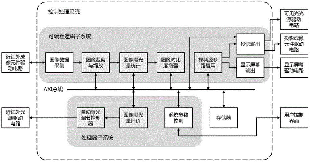
本发明所描述的控制处理系统结构连接框图如图1所示。The structural connection block diagram of the control processing system described in the present invention is shown in FIG. 1 .
如图1所示,控制处理系统由处理器子系统、可编程逻辑子系统及存储器组成。其中,处理器子系统、可编程逻辑子系统及存储器通过AXI总线互联。近红外光源驱动电路、用户控制界面与处理器子系统信号连接。近红外成像元件驱动电路、投影成像元件驱动电路、可见光光源驱动电路及显示屏幕驱动电路与可编程逻辑子系统信号连接。As shown in Figure 1, the control processing system is composed of processor subsystem, programmable logic subsystem and memory. Among them, the processor subsystem, the programmable logic subsystem and the memory are interconnected through the AXI bus. The near-infrared light source driving circuit, the user control interface and the processor subsystem are signal-connected. The driving circuit of the near-infrared imaging element, the driving circuit of the projection imaging element, the driving circuit of the visible light source and the driving circuit of the display screen are signal-connected with the programmable logic subsystem.
其中,处理器子系统可采用ARM架构的微处理器或其它功能相近的微处理器;可编程逻辑子系统可采用FPGA(Field Programmable Gate Array,现场可编程门阵列)器件或其它功能相近的可编程逻辑器件;存储器可采用DDR(Double Data Rate,双倍数据速率)存储器或其它具有相近性能的存储器器件。Among them, the processor subsystem can adopt ARM architecture microprocessor or other microprocessors with similar functions; the programmable logic subsystem can adopt FPGA (Field Programmable Gate Array, Field Programmable Gate Array) devices or other similar functions can Program logic device; memory can adopt DDR (Double Data Rate, double data rate) memory or other memory devices with similar performance.
更进一步地,处理器子系统、可编程逻辑子系统及AXI总线可使用Zynq异构片上系统或其它功能相近的片上系统器件组成。Furthermore, the processor subsystem, programmable logic subsystem and AXI bus can be composed of Zynq heterogeneous system-on-chip or other system-on-chip devices with similar functions.
近红外光源驱动电路、近红外成像元件驱动电路、投影成像元件驱动电路、可见光光源驱动电路及显示屏幕驱动电路分别与近红外光源、近红外成像元件、投影成像元件、可见光光源及显示屏幕信号连接。The near-infrared light source drive circuit, the near-infrared imaging element drive circuit, the projection imaging element drive circuit, the visible light source drive circuit and the display screen drive circuit are respectively connected to the near-infrared light source, the near-infrared imaging element, the projection imaging element, the visible light source, and the display screen. .
图像裁剪和缩放(原位等大投影)Image cropping and scaling (in situ isometric projection)
为了使投影结果图像中的皮下静脉血管与实际感兴趣区域中的皮下静脉血管位置相重合,需要做到原位等大投影。本系统的光学成像单元利用二向色镜实现光路共轴,即图像采集光路与投影光路的中心是近似重合的,如图2及图3所示。In order to make the position of the subcutaneous venous vessel in the projection result image coincide with the position of the subcutaneous venous vessel in the actual region of interest, it is necessary to achieve the in situ isometric projection. The optical imaging unit of this system uses a dichroic mirror to realize the coaxiality of the optical path, that is, the centers of the image acquisition optical path and the projection optical path are approximately coincident, as shown in Figure 2 and Figure 3 .
虽然图像采集和投影在光路上是共轴的,但由于采集和投影的器件分辨率和镜头视场角(Field Of View,FOV)均不一致,因此,要实现原位等大投影,还需对采集的图像进行处理,其中主要包括图像等大缩放、偏移调节等操作。Although the image acquisition and projection are coaxial on the optical path, since the resolution of the acquisition and projection devices and the Field Of View (FOV) of the lens are inconsistent, it is necessary to The collected image is processed, which mainly includes operations such as image scaling and offset adjustment.
在有效工作高度h=30cm平面上,设图像采集镜头实际覆盖区域大小为a×b厘米,而投影镜头实际覆盖区域大小为c×d厘米,为了让投影出的图像与实际事物完全等大重合,那么就需要从图像传感器采集的图像中截取出被投影镜头覆盖的区域,如图3中第2部分中的斜线区域,然后将其放大至投影成像器件的分辨率,再由投影成像器件投影出来,如图3中第3部分所示,这时的投影成像就能在实际空间上与其覆盖的事物等大重合。On the plane with an effective working height of h=30cm, let the actual coverage area of the image acquisition lens be a×b cm, and the actual coverage area of the projection lens be c×d cm, in order to make the projected image coincide completely with the actual thing , then it is necessary to intercept the area covered by the projection lens from the image collected by the image sensor, such as the oblique area in
根据上面提出的设计方案,本发明中实现原位等大投影的具体步骤如下:According to the design scheme proposed above, the specific steps for realizing the in-situ equal projection in the present invention are as follows:
(1)在系统有效工作距离h=30cm的平面上,将采集到的图像先放大至投影成像器件的分辨率大小,再由其投影出来;根据投影出的图像分别测量出采集镜头和投影镜头实际覆盖区域的大小,分别记a×b和c×d为16.3×10.8cm、8.8×6.5cm,同时还测量出投影镜头覆盖区域相对采集镜头覆盖区域的偏移量x、y为3.7cm、1.3cm(1) On the plane where the effective working distance of the system is h=30cm, first enlarge the collected image to the resolution of the projection imaging device, and then project it; measure the collection lens and projection lens respectively according to the projected image The size of the actual coverage area is recorded as a×b and c×d as 16.3×10.8cm and 8.8×6.5cm respectively. At the same time, the offset x and y of the coverage area of the projection lens relative to the coverage area of the acquisition lens are measured as 3.7cm, 1.3cm
(2)根据上面测量出的数据,计算出从采集图像中需要裁剪部分的大小和偏移量。设CMOS图像传感器采集的图像分辨率为752×480像素,设需要裁剪出的部分长宽分别为

另外,设裁剪部分的起始偏移坐标为


根据计算结果,从采集的图像中截取出
(3)根据上一步骤确定的参数设计出裁剪和放大模块,模块采用基于AXI总线标准的视频流接口,内部采用后向放大算法实现图像的实时放大。(3) Design the cutting and enlarging module according to the parameters determined in the previous step. The module adopts the video stream interface based on the AXI bus standard, and internally adopts the backward enlarging algorithm to realize the real-time enlarging of the image.
在本发明中,如图4所示,图像裁剪与缩放模块作为图像数据采集后的第一级处理,用来实现原位等大投影功能。In the present invention, as shown in FIG. 4 , the image cropping and zooming module is used as the first-level processing after the image data is collected, and is used to realize the in-situ isometric projection function.
图像曝光量统计、自动曝光调节控制(近红外光源自适应曝光控制)Image exposure statistics, automatic exposure adjustment control (near-infrared light source adaptive exposure control)
本发明设计的皮下静脉显影系统需要采用近红外光源进行照明。在不同环境下,例如在室内或室外、白天或晚上、晴天或阴天,近红外光的光照情况都不一样。若近红外光光照不足,会严重影响图像数据的采集;若近红外光过强,采集的图像出现过曝光现象,同样会影响后续的处理。可见,确保最优的光照效果对系统成像质量尤为重要。The subcutaneous vein imaging system designed in the present invention needs to use a near-infrared light source for illumination. In different environments, such as indoors or outdoors, day or night, sunny or cloudy, the illumination conditions of near-infrared light are different. If the near-infrared light is insufficient, it will seriously affect the acquisition of image data; if the near-infrared light is too strong, the collected image will be overexposed, which will also affect the subsequent processing. It can be seen that ensuring the optimal lighting effect is particularly important to the system imaging quality.
近红外光源自适应曝光控制就是为了让系统图像数据采集在不同环境下都能获取最优的光照效果,为后续的图像增强处理提供稳定合适的曝光状态。本发明设计的近红外光源自适应曝光控制在本系统中作为图像数据采集后的第二级处理,根据当前获取图像的曝光情况,对系统内的近红外光源进行实时调节,其主要分为3部分:图像曝光量统计、图像曝光量评价及近红外光源自动曝光调节控制,如图4所示。The adaptive exposure control of the near-infrared light source is to enable the system image data acquisition to obtain the optimal lighting effect in different environments, and to provide a stable and appropriate exposure state for the subsequent image enhancement processing. The near-infrared light source adaptive exposure control designed by the present invention is used as the second-level processing after image data collection in this system. According to the exposure situation of the currently acquired image, the near-infrared light source in the system is adjusted in real time, which is mainly divided into 3 Part: image exposure statistics, image exposure evaluation and near-infrared light source automatic exposure adjustment control, as shown in Figure 4.
图像曝光量统计Image Exposure Statistics
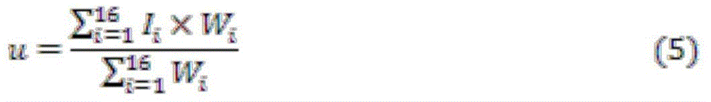
实现近红外光源自适应曝光控制,首先需要对采集的图像数据进行曝光量信息统计,统计后获得的数据再用于对近红外光源的调节。在成像过程中,用户对成像不同区域的曝光情况关心程度会有所不同,为了让用户获得更好的使用感受,在统计图像曝光量信息时应该按照用户对不同区域的关注程度设置不同权值,然后对每个区域的曝光量值进行加权平均。一般来说,用户习惯将注意力放在成像区域的中央位置,那么按照用户对成像区域的关注程度设置权重分配,成像中间区域的权重加大,四周区域的权重相对降低。成像区域划分和权重分配如图5所示:To realize the adaptive exposure control of near-infrared light sources, it is first necessary to conduct statistics on the exposure information of the collected image data, and the data obtained after the statistics are used to adjust the near-infrared light source. During the imaging process, users will have different concerns about the exposure of different areas of the image. In order to allow users to obtain a better experience, different weights should be set according to the user's attention to different areas when counting image exposure information. , and then weighted average the exposure value of each region. Generally speaking, users are used to focusing on the center of the imaging area, so the weight distribution is set according to the user's attention to the imaging area. The weight of the middle area of the imaging is increased, and the weight of the surrounding areas is relatively reduced. The imaging area division and weight distribution are shown in Figure 5:
从图5可看出,本发明将成像区域分为16个等大的区域,然后分别计算出各区域的曝光量均值Ii,其中,i为各区域的编号。设上图的权重矢量为W,那么成像区域的亮度加权均值u则为:It can be seen from FIG. 5 that the present invention divides the imaging area into 16 areas of equal size, and then calculates the average exposure value I i of each area, where i is the number of each area. Assuming that the weight vector of the above figure is W, then the weighted average value u of the brightness of the imaging area is:
自动曝光调节控制Automatic Exposure Adjustment Control
图像曝光量评价与自动曝光调节控制模块可以看成为一个典型的闭环自动控制系统,可以抽象为如图6所示:The image exposure evaluation and automatic exposure adjustment control module can be regarded as a typical closed-loop automatic control system, which can be abstracted as shown in Figure 6:
上图中,ue为图像亮度理想均值,Gc(s)为控制器的传递函数。Δw为控制增量,在本发明中为近红外光源发光亮度调节量,用于调节近红外光源的强弱,G(s)为被控单元的传递函数,在本系统中为近红外光源,H(s)则为反馈传递函数,u为前面介绍的成像区域的亮度加权均值。本发明中,控制器采用PID自动控制算法来实现。In the figure above, u e is the ideal mean value of image brightness, and G c (s) is the transfer function of the controller. Δw is the control increment, in the present invention, it is the amount of light emission brightness adjustment of the near-infrared light source, which is used to adjust the strength of the near-infrared light source, and G(s) is the transfer function of the controlled unit, which is the near-infrared light source in this system, H(s) is the feedback transfer function, and u is the weighted mean value of the brightness of the imaging area introduced earlier. In the present invention, the controller adopts PID automatic control algorithm to realize.
PID控制器是目前实际工业控制过程中应用最广泛、最稳定的一种控制算法,其输入输出关系如下式所示:PID controller is currently the most widely used and most stable control algorithm in the actual industrial control process, and its input-output relationship is shown in the following formula:
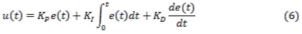
KP,KP,KD分别为比例系数、积分系数、微分系数,通过调整这3个系数即可获得理想的控制效果,具体地,Kp参数用来控制调节速度,KI参数用来消除稳态误差,KD参数用来改善系统的动态性能[34]。e(t)为系统反馈量u与系统理想值ue的误差。K P , K P , and K D are proportional coefficients, integral coefficients, and differential coefficients respectively. The ideal control effect can be obtained by adjusting these three coefficients. Specifically, the K p parameter is used to control the adjustment speed, and the K I parameter is used to control the adjustment speed. To eliminate the steady-state error, the KD parameter is used to improve the dynamic performance of the system [34] . e(t) is the error between the system feedback quantity u and the system ideal value u e .
根据控制处理系统的特点,本发明采用在可编程逻辑子系统上进行实时的图像曝光量信息统计,在处理器子系统上根据统计数据并通过PID自动控制算法进行自动曝光调节控制。其控制算法具体流程如图7所示。According to the characteristics of the control processing system, the present invention uses the programmable logic subsystem to perform real-time image exposure information statistics, and performs automatic exposure adjustment control on the processor subsystem according to the statistical data and through the PID automatic control algorithm. The specific flow of its control algorithm is shown in Figure 7.
皮下静脉图像对比度增强Contrast enhancement of subcutaneous vein images
利用对近红外光反射的差异来采集到的皮下静脉图像,其对比度通常比较低,若直接将低对比度的皮下静脉图像投影显示出来,将无法达到显影成像的效果。因此,针对皮下静脉图像的对比度增强技术是皮下静脉显影系统的关键技术,在本发明中作为图像数据采集后的第三级处理,如图4所示。The contrast of the subcutaneous vein image collected by using the difference in the reflection of near-infrared light is usually relatively low. If the low-contrast subcutaneous vein image is directly projected and displayed, the effect of imaging will not be achieved. Therefore, the contrast enhancement technology for subcutaneous vein images is the key technology of the subcutaneous vein development system, and it is used as the third-level processing after image data collection in the present invention, as shown in FIG. 4 .
基于CLAHE的改进算法Improved Algorithm Based on CLAHE
CLAHE为了在增强图像细节对比度的同时尽可能减少对噪声的放大,通过裁剪直方图来限制放大幅度,亦即限制了CDF的斜率,所以该算法的截断系数α需要在对比度增强效果和噪声抑制程度的权衡间取值。若为了获取最大的对比度增强效果,截断系数α就需要取较大的值,那么对噪声的抑制程度也会减弱。本发明针对静脉图像的特点,对原有的CLAHE进行改进,目的是进一步提高静脉图像对比度增强效果,同时兼顾图像背景噪声放大的抑制。In order to reduce the amplification of noise as much as possible while enhancing the contrast of image details, CLAHE limits the amplification by clipping the histogram, that is, limits the slope of the CDF. Therefore, the truncation coefficient α of the algorithm needs to be in contrast enhancement effect and noise suppression degree. The value of the trade-off between . If in order to obtain the maximum contrast enhancement effect, the truncation coefficient α needs to take a larger value, and the degree of noise suppression will also be weakened. According to the characteristics of vein images, the present invention improves the original CLAHE, aiming at further improving the contrast enhancement effect of vein images, and at the same time taking into account the suppression of image background noise amplification.
为了得到最大的对比度增强效果,本发明在原有的CLAHE基础上,提出了改进,主要包括两点:去除直方图的裁剪和重分配这一步骤;对CDF映射函数进行改进。本发明提出的基于CLAHE改进算法具体步骤如下:In order to obtain the maximum contrast enhancement effect, the present invention proposes an improvement on the basis of the original CLAHE, which mainly includes two points: removing the step of clipping and redistribution of the histogram; and improving the CDF mapping function. The concrete steps based on the improved algorithm of CLAHE that the present invention proposes are as follows:
(1)图像分块(1) Image segmentation
该步骤与上一节介绍的CLAHE一致。本发明将输入图像分为4×4非重叠子块。This step is consistent with CLAHE introduced in the previous section. The present invention divides the input image into 4x4 non-overlapping sub-blocks.
(2)统计各子块的直方图(2) Statistical histogram of each sub-block
每个子块的直方图分别记作Hi,j(k),其中i,j=1,2,3,4。在统计完各子块直方图后,本方法不对直方图进行裁剪和重分配,而是进行下一步骤。The histogram of each sub-block is denoted as H i,j (k), where i,j=1,2,3,4. After counting the histograms of each sub-block, this method does not cut and redistribute the histograms, but proceeds to the next step.
(3)计算各子块的混合累计分布函数(Hybrid Cumulative DistributionFunction,HCDF)(3) Calculate the hybrid cumulative distribution function (Hybrid Cumulative Distribution Function, HCDF) of each sub-block
在上面的分析中,皮下静脉图像的背景多集中在低灰度级部分,而静脉血管则隐藏在中高灰度级部分,因此在该步骤中需要确定一个阀值Th,将直方图分为两部分,小于Th的属于图像背景部分,而大于Th则为感兴趣区域。由于本发明设计的近红外光源自适应曝光控制能保证系统采集的图像的亮度均值维持在一个稳定状态,因此用来划分图像背景和感兴趣区域的阀值Th不需动态调整。为了提高算法对感兴趣区域的增强效果,同时减少对背景噪声的放大,本发明对原有方法的CDF进行改进,设计出混合累计分布函数(HybridCumulative Distribution Function,HCDF),如下式所示:In the above analysis, the background of the subcutaneous vein image is mostly concentrated in the low gray level part, while the venous blood vessels are hidden in the middle and high gray level part, so a threshold Th needs to be determined in this step, and the histogram is divided into two parts. The part smaller than Th belongs to the background part of the image, while the part larger than Th is the region of interest. Since the adaptive exposure control of the near-infrared light source designed in the present invention can ensure that the average brightness of the image collected by the system is maintained in a stable state, the threshold Th used to divide the image background and the region of interest does not need to be dynamically adjusted. In order to improve the enhancement effect of the algorithm on the region of interest and reduce the amplification of background noise, the present invention improves the CDF of the original method and designs a hybrid cumulative distribution function (Hybrid Cumulative Distribution Function, HCDF), as shown in the following formula:

该混合累计分布函数(HCDF)能对图像背景和感兴趣区域起到不同的增强效果,其中,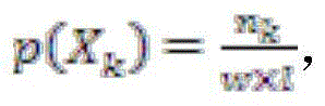

相应地,本发明提出的混合累计分布函数(HCDF)的斜率计算为:Correspondingly, the slope of the mixed cumulative distribution function (HCDF) proposed by the present invention is calculated as:

在处理图像的背景部分时,即灰度级在0<k<Th之间,有:When processing the background part of the image, that is, the gray level is between 0<k<Th, there are:

当处理灰度级在Th≤k<L之间的图像区域时,有:When dealing with image areas with gray levels between Th≤k<L, there are:

从上可见,HCDF对图像背景部分的增强作用要比原有的CDF增强作用小,即HCDF对背景噪声的放大起到一定抑制作用;另一方面,HCDF对图像中的感兴趣区域的增强作用则比原有的CDF增强作用大,该算法的增强效果得到进一步提高。在进行到下一个步骤之前,还须要对HCDF执行归一化操作处理。归一化处理后的HCDF表示为:It can be seen from the above that the enhancement effect of HCDF on the background part of the image is smaller than that of the original CDF, that is, the HCDF has a certain inhibitory effect on the amplification of background noise; on the other hand, the enhancement effect of HCDF on the region of interest in the image It is stronger than the original CDF enhancement, and the enhancement effect of the algorithm is further improved. Before proceeding to the next step, it is also necessary to perform a normalization operation on the HCDF. The normalized HCDF is expressed as:
(4)建立各子块的输出映射函数(4) Establish the output mapping function of each sub-block
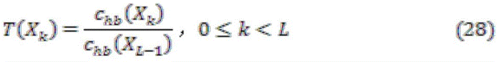
这一步骤与原有的CLAHE算法相似。设上一步骤得出的各子块混合累计分布函数(HCDF)为Ti,j(Xk),i、j分别为图像分块的纵横编号,那么基于HCDF的输出映射函数为:This step is similar to the original CLAHE algorithm. Assuming that the mixed cumulative distribution function (HCDF) of each sub-block obtained in the previous step is T i, j (X k ), and i, j are the vertical and horizontal numbers of the image block respectively, then the output mapping function based on HCDF is:
zi,j(x)=X0+(XL-1-X0)Ti,j(x),i,j=1,2,3,4 (29)z i, j (x) = X 0 + (X L-1 -X 0 )T i, j (x), i, j = 1, 2, 3, 4 (29)
(5)像素重构映射(5) Pixel reconstruction mapping
这一步骤与原有CLAHE算法一致,基于上一步骤得出的各子块输出映射函数,以各子块中央位置作为基点,使用双线性插值方法重构图像各个像素点的灰度值。如图8所示。This step is consistent with the original CLAHE algorithm. Based on the output mapping function of each sub-block obtained in the previous step, the central position of each sub-block is used as the base point, and the gray value of each pixel of the image is reconstructed using the bilinear interpolation method. As shown in Figure 8.
设像素点p位于子块(i,j)的左上方,那么根据p点与其最邻近参考点的位置关系确定权值,最后根据下式计算最终的加权结果:Assuming that the pixel point p is located at the upper left of the sub-block (i, j), then the weight is determined according to the positional relationship between point p and its nearest neighbor reference point, and finally the final weighted result is calculated according to the following formula:

改进算法的实现Implementation of improved algorithm
根据控制处理系统的特点,本发明设计的图像对比度增强模块按照功能划分,可分为4个子模块:直方图统计模块、映射建立/输出模块、双线性插值重构模块以及子块偏移量计算模块。整体框架图9所示。According to the characteristics of the control processing system, the image contrast enhancement module designed by the present invention can be divided into four sub-modules according to the functions: histogram statistics module, mapping establishment/output module, bilinear interpolation reconstruction module and sub-block offset computing module. The overall framework is shown in Figure 9.
这里使用了直方图统计和映射输出同步进行的设计方法,因为视频流是具有连续性的,所以相邻帧图像的直方图具有非常高的相似性。模块内部采用流水线方式设计,在第n帧有效场期间,视频流数据同时进入直方图统计模块和映射建立/输出模块,这样直方图统计和映射表查找输出操作则同时进行。从映射建立/输出模块流出的数据经过双线性插值模块进行像素重构。在第n帧场消隐期间,视频流数据停止传输,此时映射建立/输出模块从直方图统计模块中读取已统计好的直方图,进行映射表的建立,供下一帧图像的映射输出使用。第n+1帧的视频流数据将使用第n帧场消隐期间建立的映射表进行映射输出。Here, the design method of synchronously performing histogram statistics and mapping output is used. Because the video stream is continuous, the histograms of adjacent frame images have a very high similarity. The interior of the module adopts a pipeline design. During the effective field period of the nth frame, the video stream data enters the histogram statistics module and the mapping establishment/output module at the same time, so that the histogram statistics and mapping table lookup output operations are performed simultaneously. The data flowing out from the mapping establishment/output module undergoes pixel reconstruction through the bilinear interpolation module. During the field blanking period of the nth frame, the transmission of the video stream data is stopped. At this time, the mapping establishment/output module reads the calculated histogram from the histogram statistics module, and establishes a mapping table for the mapping of the next frame of image output using . The video stream data of the n+1th frame will be mapped and output using the mapping table established during the field blanking period of the nth frame.
(1)子块偏移量计算模块(1) Sub-block offset calculation module
该模块通过对视频流输入的当前像素进行定位跟踪,计算出当前像素所在的子块编号i,j,以及像素在子块内的相对坐标m,n,a,b。直方图统计模块和双线性插值模块则根据这些统计信息完成数据选取、权值计算等操作。This module calculates the sub-block number i, j where the current pixel is located, and the relative coordinates m, n, a, b of the pixel in the sub-block by performing positioning and tracking on the current pixel input by the video stream. The histogram statistical module and bilinear interpolation module complete data selection, weight calculation and other operations based on these statistical information.
(2)直方图统计模块(2) Histogram statistics module
模块内有1个行缓冲RAM和16个直方图统计RAM,具体架构图10所示。在有效场期间,视频流数据首先写入行缓冲RAM,每一个时钟周期写入一个像素值。当填满一行数据后,一级的视频流暂停传输,此时开始读取行缓冲RAM进行直方图统计,结合子块偏移量计算模块给出的子块编号,将计算结果输入到相应子块的直方图统计RAM中。从行缓冲RAM读取像素值后,下一个时钟周期从相应子块直方图统计RAM读取数据并累加,再下一个时钟周期将累加结果重新写入相应子块直方图统计RAM,这三个步骤总共需要三个时钟周期。当读完行缓冲RAM数据后,上一级模块重新开始下一行数据传输。There is 1 line buffer RAM and 16 histogram statistical RAMs in the module, the specific architecture is shown in Figure 10. During the active field, the video stream data is first written into the line buffer RAM, and a pixel value is written into each clock cycle. When a line of data is filled, the transmission of the first-level video stream is suspended. At this time, the line buffer RAM is read for histogram statistics. Combined with the sub-block number given by the sub-block offset calculation module, the calculation result is input to the corresponding sub-block. Block histogram statistics in RAM. After reading the pixel value from the line buffer RAM, the next clock cycle reads the data from the corresponding sub-block histogram statistical RAM and accumulates, and then rewrites the accumulated result to the corresponding sub-block histogram statistical RAM in the next clock cycle. The steps take a total of three clock cycles. After reading the line buffer RAM data, the upper level module restarts the next line of data transmission.
当一帧图像传输完后,进入场消隐时间,这时各子块直方图已统计完成,映射建立/输出模块则从直方图统计RAM读取数据来建立各子块相应的映射表。映射表建立完成后,直方图统计RAM将会置零,然后等候下一个有效场数据。(3)映射建立/输出模块When a frame of image is transmitted, it enters the field blanking time. At this time, the histogram of each sub-block has been counted, and the mapping establishment/output module reads data from the histogram statistics RAM to establish the corresponding mapping table of each sub-block. After the mapping table is established, the histogram statistics RAM will be set to zero, and then wait for the next effective field data. (3) Mapping establishment/output module
映射建立/输出模块架构如图11所示,该模块有直方图累加模块,映射表建立计算模块和16个映射表RAM,分别对应16个子块。在视频有效场期间,映射建立/输出模块接收视频流数据,并进行映射表RAM查找输出。在视频场消隐期间,直方图累加模块从直方图统计RAM中读取数据进行累加,并将结果传到映射表计算模块。映射表计算模块基于本文提出的混合累计分布函数(HCDF),进行映射表建立。具体地,公式(23)中p(Xj)×0.2和p(Xj)×log2(j)的乘法操作采用了查找表(Look Up Table,LUT)方式来实现,这样既提高了处理速度,也节省了乘法器资源。直方图累加模块和映射表计算模块的数据处理采用流水线方式设计,最终的计算结果写入相应的映射表RAM中。模块内各子块的计算是并行处理的,互不影响,这样能大大提高算法的处理速度,满足系统的实时性需求。The architecture of the mapping establishment/output module is shown in Figure 11. This module has a histogram accumulation module, a mapping table establishment calculation module and 16 mapping table RAMs, corresponding to 16 sub-blocks. During the effective field of video, the mapping establishment/output module receives video stream data, and performs mapping table RAM lookup and output. During the blanking period of the video field, the histogram accumulation module reads data from the histogram statistical RAM for accumulation, and transmits the result to the mapping table calculation module. The mapping table calculation module establishes the mapping table based on the hybrid cumulative distribution function (HCDF) proposed in this paper. Specifically, the multiplication operation of p(X j )×0.2 and p(X j )×log 2 (j) in formula (23) is implemented by using a look-up table (Look Up Table, LUT), which not only improves the processing speed, and also saves multiplier resources. The data processing of the histogram accumulation module and the mapping table calculation module adopts a pipeline design, and the final calculation results are written into the corresponding mapping table RAM. The calculation of each sub-block in the module is processed in parallel without affecting each other, which can greatly improve the processing speed of the algorithm and meet the real-time requirements of the system.
(4)双线性插值模块(4) Bilinear interpolation module
有效场期间,本模块从映射表RAM中读取数据,并进行双线性插值重构输出。在实现双线性插值前,先对式(22)进行化简,以便于硬件实现。化简式如下所示:During the effective field period, this module reads data from the mapping table RAM, and performs bilinear interpolation to reconstruct the output. Before implementing bilinear interpolation, formula (22) should be simplified to facilitate hardware implementation. The simplification looks like this:

模块涉及数据选取、权值计算、插值规则选择、加权乘累加等多个操作,因此,这里使用了多级流水线设计方法,使其获得最大的数据吞吐量,计算性能达到最优。双线性插值的流水线结构框架如图12所示。The module involves multiple operations such as data selection, weight calculation, interpolation rule selection, weighted multiplication and accumulation, etc. Therefore, a multi-stage pipeline design method is used here to obtain the maximum data throughput and optimal computing performance. The pipeline structure framework of bilinear interpolation is shown in Figure 12.
图中,双线性插值模块采用了四级流水线设计,其中,加权乘累加模块内还内嵌一个流水线。In the figure, the bilinear interpolation module adopts a four-stage pipeline design, and a pipeline is embedded in the weighted multiply-accumulate module.
双路同步显示(视频源多路复用)Dual synchronous display (multiplexing of video sources)
如图4所示,视频源多路复用模块在本发明中作为视频输出前最后一级处理,用来实现投影成像元件和显示屏幕双路同步显示输出功能。As shown in FIG. 4 , the video source multiplexing module is used as the last stage of processing before video output in the present invention, and is used to realize the dual synchronous display output function of the projection imaging element and the display screen.
双路同步显示功能是本发明的一个创新性设计,该功能使系统在经过投影成像元件投影成像的同时,能在显示屏幕上进行同步显示,这样既能帮助医护人员对皮下静脉的位置进行双重确认、提高穿刺精确度,又能符合医护人员不同的操作习惯。The dual-channel synchronous display function is an innovative design of the present invention. This function enables the system to simultaneously display on the display screen while projecting images through the projection imaging element, which can help medical staff double-check the position of subcutaneous veins. Confirm and improve the puncture accuracy, and meet the different operating habits of medical staff.
图13中,各模块部件均采用AXI总线接口进行互联,其实现具体流程如下:In Figure 13, all module components are interconnected using AXI bus interface, and the specific implementation process is as follows:
(1)在有效场期间,视频流数据不断流入多路复用模块。(1) During the active field, the video stream data continuously flows into the multiplexing module.
(2)多路复用模块以隔行切换模式,将输入视频流数据分别切换到不同的通路,例如输入视频流第i行数据流入DMA(Direct Memory Access,存储器直接访问)0模块,而下一行的数据则切换到DMA 1模块。(2) The multiplexing module switches the input video stream data to different channels in an interlaced switching mode, for example, the i-th line of input video stream data flows into the DMA (Direct Memory Access, memory direct access) 0 module, and the next line The data is switched to the
(3)DMA 0模块和DMA 1模块接收上一级的视频流数据,通过DMA将其写入内存中的两个不同块区,并分别供投影成像元件和显示屏幕读取。每个模块内还采用了乒乓操作的设计,这样使得视频缓存和视频读取能同时进行,并使得下一级处理和上一级处理分隔开来。(3)
(4)两个通路通过DMA分别读取相应块区的视频缓冲数据,然后通过图像缩放模块,缩放至合适的输出分辨率大小。(4) The two channels respectively read the video buffer data of the corresponding block area through DMA, and then scale to the appropriate output resolution size through the image scaling module.
(5)输出的两路视频流数据分别流向投影成像元件驱动电路模块和显示屏幕驱动电路模块,从而实现单一视频源的双路同步显示。(5) The output two-way video stream data flows to the projection imaging element drive circuit module and the display screen drive circuit module respectively, thereby realizing dual-way synchronous display of a single video source.
Claims (5)
Priority Applications (3)
| Application Number | Priority Date | Filing Date | Title |
|---|---|---|---|
| CN201610356998.8A CN106023057B (en) | 2016-05-26 | 2016-05-26 | A control processing system and imaging method for a subcutaneous vein imaging device |
| PCT/CN2016/101513 WO2017201942A1 (en) | 2016-05-26 | 2016-10-08 | Control processing system and imaging method for subcutaneous vein developing device |
| US16/304,560 US20190167110A1 (en) | 2016-05-26 | 2016-10-08 | Control processing system and imaging method for subcutaneous vein developing device |
Applications Claiming Priority (1)
| Application Number | Priority Date | Filing Date | Title |
|---|---|---|---|
| CN201610356998.8A CN106023057B (en) | 2016-05-26 | 2016-05-26 | A control processing system and imaging method for a subcutaneous vein imaging device |
Publications (2)
| Publication Number | Publication Date |
|---|---|
| CN106023057A CN106023057A (en) | 2016-10-12 |
| CN106023057B true CN106023057B (en) | 2022-11-08 |
Family
ID=57093780
Family Applications (1)
| Application Number | Title | Priority Date | Filing Date |
|---|---|---|---|
| CN201610356998.8A Active CN106023057B (en) | 2016-05-26 | 2016-05-26 | A control processing system and imaging method for a subcutaneous vein imaging device |
Country Status (3)
| Country | Link |
|---|---|
| US (1) | US20190167110A1 (en) |
| CN (1) | CN106023057B (en) |
| WO (1) | WO2017201942A1 (en) |
Families Citing this family (4)
| Publication number | Priority date | Publication date | Assignee | Title |
|---|---|---|---|---|
| CN111292267B (en) * | 2020-02-04 | 2020-10-23 | 北京锐影医疗技术有限公司 | Image subjective visual effect enhancement method based on Laplacian pyramid |
| CN111709898B (en) * | 2020-06-20 | 2023-05-23 | 昆明物理研究所 | Infrared image enhancement method and system based on optimized CLAHE |
| WO2022051775A1 (en) | 2020-09-04 | 2022-03-10 | Abova, Inc. | Method for x-ray dental image enhancement |
| CN115174763B (en) * | 2022-07-05 | 2024-11-19 | 重庆邮电大学 | ZYNQ-based image real-time display system |
Citations (1)
| Publication number | Priority date | Publication date | Assignee | Title |
|---|---|---|---|---|
| CN103337071A (en) * | 2013-06-19 | 2013-10-02 | 北京理工大学 | Device and method for structure-reconstruction-based subcutaneous vein three-dimensional visualization |
Family Cites Families (7)
| Publication number | Priority date | Publication date | Assignee | Title |
|---|---|---|---|---|
| US8676296B2 (en) * | 2008-09-15 | 2014-03-18 | Univerity of Pittsburgh—Of The Commonwealth System of Higher Education | Echo-specific K-space reordering approach to compatible dual-echo arteriovenography |
| US8996086B2 (en) * | 2010-09-17 | 2015-03-31 | OptimumTechnologies, Inc. | Digital mapping system and method |
| US9072426B2 (en) * | 2012-08-02 | 2015-07-07 | AccuVein, Inc | Device for detecting and illuminating vasculature using an FPGA |
| CN103491328A (en) * | 2013-06-26 | 2014-01-01 | 苏州联科盛世科技有限公司 | Vein projector with image correction function and image correction method |
| CN104146683A (en) * | 2014-04-24 | 2014-11-19 | 深圳大学 | Vein viewing instrument and imaging method thereof |
| CN104123703B (en) * | 2014-07-09 | 2017-04-12 | 广州中国科学院先进技术研究所 | Primary skin color keeping vein development method |
| CN105581780B (en) * | 2015-12-16 | 2018-11-02 | 深圳大学 | A kind of adpative exposure control method and system for venae subcutaneae imager |
-
2016
- 2016-05-26 CN CN201610356998.8A patent/CN106023057B/en active Active
- 2016-10-08 US US16/304,560 patent/US20190167110A1/en not_active Abandoned
- 2016-10-08 WO PCT/CN2016/101513 patent/WO2017201942A1/en not_active Ceased
Patent Citations (1)
| Publication number | Priority date | Publication date | Assignee | Title |
|---|---|---|---|---|
| CN103337071A (en) * | 2013-06-19 | 2013-10-02 | 北京理工大学 | Device and method for structure-reconstruction-based subcutaneous vein three-dimensional visualization |
Non-Patent Citations (1)
| Title |
|---|
| 一种基于近红外-可见光映射的快捷静脉提取算法;唐超颖;《东南大学学报(自然科学版)》;20160120(第01期);全文 * |
Also Published As
| Publication number | Publication date |
|---|---|
| WO2017201942A1 (en) | 2017-11-30 |
| CN106023057A (en) | 2016-10-12 |
| US20190167110A1 (en) | 2019-06-06 |
Similar Documents
| Publication | Publication Date | Title |
|---|---|---|
| EP3739431B1 (en) | Method for determining point of gaze, contrast adjustment method and device, virtual reality apparatus, and storage medium | |
| CN106023057B (en) | A control processing system and imaging method for a subcutaneous vein imaging device | |
| Wang et al. | Smartphone-based wound assessment system for patients with diabetes | |
| Zhu et al. | Neuspike-net: High speed video reconstruction via bio-inspired neuromorphic cameras | |
| WO2020259264A1 (en) | Subject tracking method, electronic apparatus, and computer-readable storage medium | |
| CN108154494A (en) | A kind of image fusion system based on low-light and infrared sensor | |
| US10721392B2 (en) | Method and a system for eye tracking | |
| WO2020133636A1 (en) | Method and system for intelligent envelope detection and warning in prostate surgery | |
| WO2019222889A1 (en) | Image feature extraction method and device | |
| WO2023142781A1 (en) | Image three-dimensional reconstruction method and apparatus, electronic device, and storage medium | |
| CN110620885B (en) | Infrared low-light-level image fusion system and method and electronic equipment | |
| Hu et al. | Fully automatic pediatric echocardiography segmentation using deep convolutional networks based on BiSeNet | |
| CN115546156A (en) | Thyroid ultrasound abnormal region capturing method and system and electronic equipment | |
| CN106137235A (en) | C-arm X-ray machine, control system and medical image system | |
| CN107388201A (en) | The dynamic control operation illuminating lamp of medical wear-type eye | |
| CN114926448B (en) | A method for extracting feature points from capsule endoscope images | |
| US11009946B2 (en) | Pupil center positioning apparatus and method, and virtual reality device | |
| WO2020087204A1 (en) | Display screen operating method, electronic device, and readable storage medium | |
| CN205942800U (en) | A control processing system for venae subcutaneae visualizer | |
| CN108184062B (en) | High-speed tracking system and method based on multi-level heterogeneous parallel processing | |
| CN109978787B (en) | Image processing method based on biological visual computing model | |
| CN113112507B (en) | Perfusion image analysis method, system, electronic equipment and storage medium | |
| CN115587981A (en) | Vein re-projection system method and terminal based on FPGA | |
| CN110322420A (en) | Image processing method and image processing system for electronic endoscope system | |
| CN115829887B (en) | Blood vessel image processing method, device and electronic equipment |
Legal Events
| Date | Code | Title | Description |
|---|---|---|---|
| C06 | Publication | ||
| PB01 | Publication | ||
| C10 | Entry into substantive examination | ||
| SE01 | Entry into force of request for substantive examination | ||
| GR01 | Patent grant | ||
| GR01 | Patent grant |