CN105824168B - lens shifter - Google Patents
lens shifter Download PDFInfo
- Publication number
- CN105824168B CN105824168B CN201610049681.XA CN201610049681A CN105824168B CN 105824168 B CN105824168 B CN 105824168B CN 201610049681 A CN201610049681 A CN 201610049681A CN 105824168 B CN105824168 B CN 105824168B
- Authority
- CN
- China
- Prior art keywords
- elastic member
- housing
- magnet
- coil
- bobbin
- Prior art date
- Legal status (The legal status is an assumption and is not a legal conclusion. Google has not performed a legal analysis and makes no representation as to the accuracy of the status listed.)
- Active
Links
Images


Classifications
-
- G—PHYSICS
- G03—PHOTOGRAPHY; CINEMATOGRAPHY; ANALOGOUS TECHNIQUES USING WAVES OTHER THAN OPTICAL WAVES; ELECTROGRAPHY; HOLOGRAPHY
- G03B—APPARATUS OR ARRANGEMENTS FOR TAKING PHOTOGRAPHS OR FOR PROJECTING OR VIEWING THEM; APPARATUS OR ARRANGEMENTS EMPLOYING ANALOGOUS TECHNIQUES USING WAVES OTHER THAN OPTICAL WAVES; ACCESSORIES THEREFOR
- G03B3/00—Focusing arrangements of general interest for cameras, projectors or printers
- G03B3/10—Power-operated focusing
-
- G—PHYSICS
- G02—OPTICS
- G02B—OPTICAL ELEMENTS, SYSTEMS OR APPARATUS
- G02B27/00—Optical systems or apparatus not provided for by any of the groups G02B1/00 - G02B26/00, G02B30/00
- G02B27/64—Imaging systems using optical elements for stabilisation of the lateral and angular position of the image
- G02B27/646—Imaging systems using optical elements for stabilisation of the lateral and angular position of the image compensating for small deviations, e.g. due to vibration or shake
-
- G—PHYSICS
- G02—OPTICS
- G02B—OPTICAL ELEMENTS, SYSTEMS OR APPARATUS
- G02B7/00—Mountings, adjusting means, or light-tight connections, for optical elements
- G02B7/02—Mountings, adjusting means, or light-tight connections, for optical elements for lenses
- G02B7/023—Mountings, adjusting means, or light-tight connections, for optical elements for lenses permitting adjustment
-
- G—PHYSICS
- G02—OPTICS
- G02B—OPTICAL ELEMENTS, SYSTEMS OR APPARATUS
- G02B7/00—Mountings, adjusting means, or light-tight connections, for optical elements
- G02B7/02—Mountings, adjusting means, or light-tight connections, for optical elements for lenses
- G02B7/04—Mountings, adjusting means, or light-tight connections, for optical elements for lenses with mechanism for focusing or varying magnification
- G02B7/08—Mountings, adjusting means, or light-tight connections, for optical elements for lenses with mechanism for focusing or varying magnification adapted to co-operate with a remote control mechanism
-
- G—PHYSICS
- G02—OPTICS
- G02B—OPTICAL ELEMENTS, SYSTEMS OR APPARATUS
- G02B7/00—Mountings, adjusting means, or light-tight connections, for optical elements
- G02B7/02—Mountings, adjusting means, or light-tight connections, for optical elements for lenses
- G02B7/04—Mountings, adjusting means, or light-tight connections, for optical elements for lenses with mechanism for focusing or varying magnification
- G02B7/09—Mountings, adjusting means, or light-tight connections, for optical elements for lenses with mechanism for focusing or varying magnification adapted for automatic focusing or varying magnification
-
- G—PHYSICS
- G02—OPTICS
- G02B—OPTICAL ELEMENTS, SYSTEMS OR APPARATUS
- G02B7/00—Mountings, adjusting means, or light-tight connections, for optical elements
- G02B7/28—Systems for automatic generation of focusing signals
-
- G—PHYSICS
- G03—PHOTOGRAPHY; CINEMATOGRAPHY; ANALOGOUS TECHNIQUES USING WAVES OTHER THAN OPTICAL WAVES; ELECTROGRAPHY; HOLOGRAPHY
- G03B—APPARATUS OR ARRANGEMENTS FOR TAKING PHOTOGRAPHS OR FOR PROJECTING OR VIEWING THEM; APPARATUS OR ARRANGEMENTS EMPLOYING ANALOGOUS TECHNIQUES USING WAVES OTHER THAN OPTICAL WAVES; ACCESSORIES THEREFOR
- G03B13/00—Viewfinders; Focusing aids for cameras; Means for focusing for cameras; Autofocus systems for cameras
- G03B13/32—Means for focusing
- G03B13/34—Power focusing
- G03B13/36—Autofocus systems
-
- G—PHYSICS
- G03—PHOTOGRAPHY; CINEMATOGRAPHY; ANALOGOUS TECHNIQUES USING WAVES OTHER THAN OPTICAL WAVES; ELECTROGRAPHY; HOLOGRAPHY
- G03B—APPARATUS OR ARRANGEMENTS FOR TAKING PHOTOGRAPHS OR FOR PROJECTING OR VIEWING THEM; APPARATUS OR ARRANGEMENTS EMPLOYING ANALOGOUS TECHNIQUES USING WAVES OTHER THAN OPTICAL WAVES; ACCESSORIES THEREFOR
- G03B17/00—Details of cameras or camera bodies; Accessories therefor
- G03B17/02—Bodies
- G03B17/12—Bodies with means for supporting objectives, supplementary lenses, filters, masks, or turrets
-
- G—PHYSICS
- G03—PHOTOGRAPHY; CINEMATOGRAPHY; ANALOGOUS TECHNIQUES USING WAVES OTHER THAN OPTICAL WAVES; ELECTROGRAPHY; HOLOGRAPHY
- G03B—APPARATUS OR ARRANGEMENTS FOR TAKING PHOTOGRAPHS OR FOR PROJECTING OR VIEWING THEM; APPARATUS OR ARRANGEMENTS EMPLOYING ANALOGOUS TECHNIQUES USING WAVES OTHER THAN OPTICAL WAVES; ACCESSORIES THEREFOR
- G03B5/00—Adjustment of optical system relative to image or object surface other than for focusing
- G03B5/04—Vertical adjustment of lens; Rising fronts
-
- H—ELECTRICITY
- H04—ELECTRIC COMMUNICATION TECHNIQUE
- H04N—PICTORIAL COMMUNICATION, e.g. TELEVISION
- H04N23/00—Cameras or camera modules comprising electronic image sensors; Control thereof
- H04N23/50—Constructional details
- H04N23/54—Mounting of pick-up tubes, electronic image sensors, deviation or focusing coils
-
- H—ELECTRICITY
- H04—ELECTRIC COMMUNICATION TECHNIQUE
- H04N—PICTORIAL COMMUNICATION, e.g. TELEVISION
- H04N23/00—Cameras or camera modules comprising electronic image sensors; Control thereof
- H04N23/50—Constructional details
- H04N23/55—Optical parts specially adapted for electronic image sensors; Mounting thereof
-
- H—ELECTRICITY
- H04—ELECTRIC COMMUNICATION TECHNIQUE
- H04N—PICTORIAL COMMUNICATION, e.g. TELEVISION
- H04N23/00—Cameras or camera modules comprising electronic image sensors; Control thereof
- H04N23/60—Control of cameras or camera modules
- H04N23/68—Control of cameras or camera modules for stable pick-up of the scene, e.g. compensating for camera body vibrations
- H04N23/682—Vibration or motion blur correction
- H04N23/685—Vibration or motion blur correction performed by mechanical compensation
- H04N23/687—Vibration or motion blur correction performed by mechanical compensation by shifting the lens or sensor position
-
- G—PHYSICS
- G03—PHOTOGRAPHY; CINEMATOGRAPHY; ANALOGOUS TECHNIQUES USING WAVES OTHER THAN OPTICAL WAVES; ELECTROGRAPHY; HOLOGRAPHY
- G03B—APPARATUS OR ARRANGEMENTS FOR TAKING PHOTOGRAPHS OR FOR PROJECTING OR VIEWING THEM; APPARATUS OR ARRANGEMENTS EMPLOYING ANALOGOUS TECHNIQUES USING WAVES OTHER THAN OPTICAL WAVES; ACCESSORIES THEREFOR
- G03B2205/00—Adjustment of optical system relative to image or object surface other than for focusing
- G03B2205/0007—Movement of one or more optical elements for control of motion blur
- G03B2205/0023—Movement of one or more optical elements for control of motion blur by tilting or inclining one or more optical elements with respect to the optical axis
-
- G—PHYSICS
- G03—PHOTOGRAPHY; CINEMATOGRAPHY; ANALOGOUS TECHNIQUES USING WAVES OTHER THAN OPTICAL WAVES; ELECTROGRAPHY; HOLOGRAPHY
- G03B—APPARATUS OR ARRANGEMENTS FOR TAKING PHOTOGRAPHS OR FOR PROJECTING OR VIEWING THEM; APPARATUS OR ARRANGEMENTS EMPLOYING ANALOGOUS TECHNIQUES USING WAVES OTHER THAN OPTICAL WAVES; ACCESSORIES THEREFOR
- G03B2205/00—Adjustment of optical system relative to image or object surface other than for focusing
- G03B2205/0053—Driving means for the movement of one or more optical element
- G03B2205/0069—Driving means for the movement of one or more optical element using electromagnetic actuators, e.g. voice coils
Landscapes
- Physics & Mathematics (AREA)
- General Physics & Mathematics (AREA)
- Optics & Photonics (AREA)
- Engineering & Computer Science (AREA)
- Multimedia (AREA)
- Signal Processing (AREA)
- Lens Barrels (AREA)
- Adjustment Of Camera Lenses (AREA)
- Power Engineering (AREA)
Abstract
公开了一种透镜移动装置。该透镜移动装置包括:移动单元,该移动单元中安装有至少一个透镜并且可以通过在磁体与线圈之间的电磁相互作用来移动;弹性构件,所述弹性构件用于支承所述移动单元;以及位置传感器,所述位置传感器用于感测从所述磁体发出的电磁力随该移动单元移动的变化并基于感测结果输出输出信号,其中,根据所述位置传感器的输出信号与施加给所述线圈的输入信号之比的增益的频率响应特性的一级谐振频率是30Hz至200Hz。
A lens moving device is disclosed. The lens moving device includes: a moving unit in which at least one lens is mounted and is movable by electromagnetic interaction between a magnet and a coil; an elastic member for supporting the moving unit; and a position sensor for sensing changes in the electromagnetic force emitted from the magnet as the moving unit moves and outputting an output signal based on the sensing result. The primary resonant frequency of a frequency response characteristic based on a gain of a ratio of an output signal of the position sensor to an input signal applied to the coil is 30 Hz to 200 Hz.
Description
相关申请案交叉引用Cross-reference to related applications
本申请主张于2015年1月23日向韩国提交的韩国申请No.10-2015-0011214的优先权益,该申请的全部内容通过引用的方式被并入到本文中如同在本文中得到完全阐述。This application claims the benefit of priority from Korean Application No. 10-2015-0011214, filed in Korea on Jan. 23, 2015, the entire contents of which are incorporated herein by reference as if fully set forth herein.
技术领域technical field
本发明涉及一种透镜移动装置。The present invention relates to a lens moving device.
背景技术Background technique
一般来说,很难将在一般摄像头模块中使用的音圈电机(VCM)技术应用于低功耗的超微型(micromini)摄像头模块中,因此,已经进行了关于此类超微型摄像头模块的研究工作。In general, it is difficult to apply a voice coil motor (VCM) technology used in a general camera module to a low-power micromini camera module, and therefore, research on such a micromini camera module has been conducted Work.
在诸如智能手机等小型电子产品中所安装的摄像头模块在使用中会频繁地遭受冲击,并且在拍摄时会因为使用者手抖而微微颤动。鉴于这些方面,需要研发在摄像头模块中安装额外单元以防止手抖的技术。Camera modules installed in small electronic products such as smart phones are frequently subjected to shocks during use, and may vibrate slightly due to the user's hand shaking when shooting. In view of these aspects, it is necessary to develop a technology to install an additional unit in the camera module to prevent hand shake.
已经研究出了各种用于防止手抖的单元。其中,存在一种手抖补偿技术,其中,光学模块是在垂直于光轴的x轴和y轴方向上移动。在此类技术中,光学系统在垂直于光轴的平面上移动以校正图像,因此具有不利于微型化的复杂结构。另外,还得要求对光学模块进行准确和快速的聚焦。Various units for preventing hand shake have been developed. Among them, there is a hand shake compensation technology, in which the optical module is moved in the x-axis and y-axis directions perpendicular to the optical axis. In this type of technology, the optical system is moved in a plane perpendicular to the optical axis to correct the image, and thus has a complex structure that is not conducive to miniaturization. In addition, accurate and fast focusing of the optical module is required.
发明内容SUMMARY OF THE INVENTION
实施例提供一种透镜移动装置,其可以确保稳定的自动聚焦(AF)反馈控制和光学图像稳定化(OIS)反馈控制。Embodiments provide a lens moving device that can ensure stable auto focus (AF) feedback control and optical image stabilization (OIS) feedback control.
在一个实施例中,一种透镜移动装置包括:移动单元,在所述移动单元中至少安装有一个透镜,并且所述移动单元通过在磁体与线圈之间的电磁交互来移动;弹性构件,所述弹性构件被配置为支承所述移动单元;以及位置传感器,所述位置传感器被配置为感测从所述磁体发出的电磁力随所述移动单元的移动的变化并且根据感测结果来输出输出信号,其中,根据所述位置传感器的所述输出信号与施加到所述线圈的输入信号的比值的增益的频率响应特性的一级谐振频率为30Hz至200Hz。In one embodiment, a lens moving device includes: a moving unit in which at least one lens is installed, and the moving unit is moved by electromagnetic interaction between a magnet and a coil; an elastic member, the the elastic member is configured to support the moving unit; and a position sensor configured to sense a change in electromagnetic force emitted from the magnet with the movement of the moving unit and output an output according to the sensing result signal, wherein the first-order resonance frequency of the frequency response characteristic of the gain according to the ratio of the output signal of the position sensor to the input signal applied to the coil is 30 Hz to 200 Hz.
根据所述位置传感器的输出信号与施加到所述线圈的输入信号的比值的增益的频率响应特性的二级谐振频率可以超过200Hz。The secondary resonance frequency of the frequency response characteristic of the gain according to the ratio of the output signal of the position sensor to the input signal applied to the coil may exceed 200 Hz.
所述弹性构件的宽度可以是所述弹性构件的厚度的预定倍或预定倍以上,并且所述预定倍可以是2倍至3倍。The width of the elastic member may be a predetermined multiple or more than the thickness of the elastic member, and the predetermined multiple may be 2 to 3 times.
所述弹性构件的厚度可以是30μm至50μm,所述弹性构件的宽度可以等于或大于参考宽度,并且所述参考宽度可以是60μm至100μm。The thickness of the elastic member may be 30 μm to 50 μm, the width of the elastic member may be equal to or greater than a reference width, and the reference width may be 60 μm to 100 μm.
根据所述位置传感器的输出信号与施加到所述线圈的输入信号的比值的增益的频率响应特性中的与0dB增益对应的频率可以是60Hz至200Hz。The frequency corresponding to the 0 dB gain in the frequency response characteristic of the gain according to the ratio of the output signal of the position sensor to the input signal applied to the coil may be 60 Hz to 200 Hz.
所述一级谐振频率可以是40Hz至120Hz。The primary resonance frequency may be 40 Hz to 120 Hz.
所述一级谐振频率可以是50Hz至100Hz。The primary resonance frequency may be 50 Hz to 100 Hz.
所述二级谐振频率可以是等于或大于250Hz。The secondary resonance frequency may be equal to or greater than 250 Hz.
所述弹性构件可以包括:上弹性构件,所述上弹性构件与线筒的上端和壳体的上端耦接;以及下弹性构件,所述下弹性构件与所述线筒的下端和所述壳体的下端耦接。The elastic member may include: an upper elastic member coupled with the upper end of the bobbin and the upper end of the housing; and a lower elastic member with the lower end of the bobbin and the case The lower end of the body is coupled.
所述上弹性构件和所述下弹性构件中的每一个均可以包括:与所述线筒耦接的内框架;与所述壳体耦接的外框架;以及用于将所述内框架和所述外框架连接的框架连接部分,所述框架连接部分的宽度可以是所述上弹性构件和所述下弹性构件的厚度的预定倍或预定倍以上,并且所述预定倍可以是2倍至3倍。Each of the upper elastic member and the lower elastic member may include: an inner frame coupled with the bobbin; an outer frame coupled with the housing; The frame connecting portion of the outer frame connection, the width of the frame connecting portion may be a predetermined multiple or more of the thickness of the upper elastic member and the lower elastic member, and the predetermined multiple may be 2 times to 3 times.
所述位置传感器中的每一个可以包括驱动器以执行比例积分微分(PID)控制。Each of the position sensors may include a driver to perform proportional-integral-derivative (PID) control.
在另一实施例中,一种透镜移动装置包括:线筒,所述线筒包含透镜镜筒;壳体,所述壳体用于收纳所述线筒;与所述线筒和所述壳体耦接的弹性构件;在所述线筒上设置的第一线圈;在所述壳体上设置的磁体;在所述壳体下方设置的电路板;在所述电路板上设置的第二线圈;第一位置传感器,所述第一位置传感器用于基于对所述磁体磁场强度随所述线筒移动变化进行感测的结果来输出第一输出信号;以及第二位置传感器,所述第二位置传感器用于基于对所述磁体磁场强度随所述壳体移动变化进行感测的结果来输出第二输出信号,其中,根据第一传递函数(first transfer function)的增益的频率响应特性的一级谐振频率具有30Hz至200Hz的频率域,并且根据该第一传递函数的增益的频率响应特性的二级谐振频率具有超过200Hz的频率域,并且所述第一传递函数是所述第二位置传感器的输出信号与施加到所述第二线圈的输入信号之比。In another embodiment, a lens moving device includes: a spool containing a lens barrel; a housing for accommodating the spool; and the spool and the housing A body-coupled elastic member; a first coil provided on the bobbin; a magnet provided on the housing; a circuit board provided under the housing; a second coil provided on the circuit board a coil; a first position sensor for outputting a first output signal based on a result of sensing changes in the magnetic field strength of the magnet with movement of the spool; and a second position sensor for A two-position sensor for outputting a second output signal based on a result of sensing a change in the magnetic field strength of the magnet with the movement of the housing, wherein a frequency response characteristic of a gain according to a first transfer function The primary resonance frequency has a frequency domain of 30 Hz to 200 Hz, and the secondary resonance frequency according to the frequency response characteristic of the gain of the first transfer function has a frequency domain of more than 200 Hz, and the first transfer function is the second position The ratio of the output signal of the sensor to the input signal applied to the second coil.
所述弹性构件可以包括:上弹性构件,所述上弹性构件与所述线筒的上端和所述壳体的上端耦接,以及下弹性构件,所述下弹性构件与所述线筒的下端和所述壳体的下端耦接。The elastic member may include an upper elastic member coupled with the upper end of the bobbin and the upper end of the housing, and a lower elastic member with the lower end of the bobbin is coupled to the lower end of the housing.
所述上弹性构件和所述下弹性构件的宽度可以是所述上弹性构件和所述下弹性构件的厚度的预定倍或预定倍以上,并且所述预定倍可以是2倍至3倍。The width of the upper elastic member and the lower elastic member may be a predetermined multiple or more than the thickness of the upper elastic member and the lower elastic member, and the predetermined multiple may be 2 to 3 times.
所述上弹性构件和所述下弹性构件中的每一个均可以包括与所述线筒耦接的内框架、与所述壳体耦接的外框架以及用于连接所述内框架和所述外框架的框架连接部分,并且所述上弹性构件和所述下弹性构件的宽度可以等于所述框架连接部分的宽度。Each of the upper elastic member and the lower elastic member may include an inner frame coupled with the bobbin, an outer frame coupled with the housing, and an inner frame for connecting the inner frame and the The frame connecting portion of the outer frame, and the upper elastic member and the lower elastic member may have widths equal to the width of the frame connecting portion.
所述上弹性构件和所述下弹性构件的厚度可以是30μm至50μm,所述上弹性构件和所述下弹性构件的宽度可以等于或大于参考宽度,所述参考宽度可以是60μm至100μm。Thicknesses of the upper and lower elastic members may be 30 μm to 50 μm, and widths of the upper and lower elastic members may be equal to or greater than a reference width, which may be 60 μm to 100 μm.
根据第二传递函数(second transfer function)的增益的频率响应特性的一级谐振频率可以具有30Hz至200Hz的频率域,根据第二传递函数的增益的频率响应特性的二级谐振频率可以具有超过200Hz的频率域,并且,所述第二传递函数可以是所述第一位置传感器的输出信号与施加到所述第一线圈的输入信号之比。The primary resonance frequency according to the frequency response characteristic of the gain of the second transfer function may have a frequency domain of 30 Hz to 200 Hz, and the secondary resonance frequency according to the frequency response characteristic of the gain of the second transfer function may have more than 200 Hz and the second transfer function may be the ratio of the output signal of the first position sensor to the input signal applied to the first coil.
所述第二位置传感器中的每一个可以包括驱动器以执行比例积分微分(PID)控制。Each of the second position sensors may include a driver to perform proportional-integral-derivative (PID) control.
根据第一传递函数的增益的频率响应特性的一级谐振频率可以是40Hz至120Hz,并且根据第一传递函数的增益的频率响应特性的二级谐振频率可以等于或大于250Hz。The primary resonance frequency according to the frequency response characteristic of the gain of the first transfer function may be 40 Hz to 120 Hz, and the secondary resonance frequency according to the frequency response characteristic of the gain of the first transfer function may be equal to or greater than 250 Hz.
根据第一传递函数的增益的频率响应特性的一级谐振频率可以是50Hz至100Hz,并且,根据第一传递函数的增益的频率响应特性的二级谐振频率可以等于或大于250Hz。The primary resonance frequency according to the frequency response characteristic of the gain of the first transfer function may be 50 Hz to 100 Hz, and the secondary resonance frequency according to the frequency response characteristic of the gain of the first transfer function may be equal to or greater than 250 Hz.
附图说明Description of drawings
可以参考以下附图来详细描述布置和实施例,其中,类似附图标记指代类似元件,其中:Arrangements and embodiments may be described in detail with reference to the following figures, wherein like reference numerals refer to like elements, wherein:
图1是根据一个实施例所述的透镜移动装置的分解透视图;1 is an exploded perspective view of a lens moving device according to one embodiment;
图2是图1中的透镜移动装置去除了盖部件之后的组装透视图;FIG. 2 is an assembled perspective view of the lens moving device of FIG. 1 with the cover member removed;
图3是图1中所示的线筒、第一线圈、第二磁体、第一位置传感器和传感器基板的分解透视图;3 is an exploded perspective view of the spool, first coil, second magnet, first position sensor, and sensor substrate shown in FIG. 1;
图4是图1所示壳体的透视图;Figure 4 is a perspective view of the housing shown in Figure 1;
图5是图1所示壳体和第二磁体的底部分解透视图;Figure 5 is a bottom exploded perspective view of the housing and second magnet shown in Figure 1;
图6是沿图2中的线I-I’截取的截面图;Figure 6 is a cross-sectional view taken along line I-I' in Figure 2;
图7是示出图1中所示的线筒、壳体、上弹性构件、第一位置传感器、传感器基板和多个支承构件的组装透视图;7 is an assembled perspective view showing the bobbin, the housing, the upper elastic member, the first position sensor, the sensor substrate, and the plurality of support members shown in FIG. 1;
图8是示出图1中所示的线筒、壳体、下弹性构件和支承构件的底部组装透视图;8 is a bottom assembled perspective view showing the spool, housing, lower elastic member and support member shown in FIG. 1;
图9是示出图1中所示的上弹性构件、下弹性构件、第一位置传感器、传感器基板、基部(base)、支承构件和电路板的组装透视图;9 is an assembled perspective view showing the upper elastic member, the lower elastic member, the first position sensor, the sensor substrate, the base, the support member and the circuit board shown in FIG. 1;
图10是示出图1中所示的基部、第二线圈、第二位置传感器和电路板的分解透视图;10 is an exploded perspective view showing the base, the second coil, the second position sensor and the circuit board shown in FIG. 1;
图11是示出根据一个实施例所述的传递函数(transfer function)的增益(gain)的频率响应特性的一级谐振频率和二级谐振频率的曲线图;11 is a graph showing a first-order resonance frequency and a second-order resonance frequency showing a frequency response characteristic of a gain of a transfer function according to one embodiment;
图12是图9所示的第一上弹性构件的放大图;以及FIG. 12 is an enlarged view of the first upper elastic member shown in FIG. 9; and
图13是示出根据一个实施例的透镜移动装置的AF反馈驱动控制中的根据传递函数增益的频率响应特性和根据传递函数相位(phase)的频率响应特性。13 is a diagram illustrating frequency response characteristics according to transfer function gain and frequency response characteristics according to transfer function phase in AF feedback drive control of the lens moving device according to one embodiment.
具体实施方式Detailed ways
下文中将参考附图详细描述实施例。在以下对实施例的描述中,应理解,当将每一层(膜)、区域、图案或结构称为形成在基板、层(膜)、区域、焊盘或图案之“上”或“下”时,其可以直接位于该另一元件的“上”或“下”,也可以在两者之间间接形成有一个或多个中间元件。此外,应理解,会基于附图来描述在每一元件“上”或“下”的位置关系。Hereinafter, the embodiments will be described in detail with reference to the accompanying drawings. In the following description of the embodiments, it should be understood that when each layer (film), region, pattern or structure is referred to as being formed "on" or "under" the substrate, layer (film), region, pad or pattern ”, it can be directly “on” or “under” the other element, or one or more intervening elements may be indirectly formed therebetween. Further, it should be understood that the positional relationship "on" or "under" each element will be described based on the drawings.
本领域技术人员应理解,会出于描述简易和清楚的目的夸大或缩小元件的大小或省略某些元件。另外,有关元件的大小并不意味其实际大小。此外,在附图中,相同或相似的元件被标以相同的附图标记,即使这些元件是在不同的图中示出。It will be understood by those skilled in the art that the size of elements may be exaggerated or reduced or certain elements omitted for simplicity and clarity of description. Also, the size of an element does not imply its actual size. Furthermore, in the drawings, the same or similar elements are provided with the same reference numerals even though these elements are shown in different drawings.
下文中将参考附图描述根据实施例所述的透镜移动装置。出于描述的便利,尽管会使用笛卡尔座标系(x,y,z)来描述根据实施例所述的透镜移动装置,但是本发明不限于此,并且可以使用其他座标系。在有关图中,x轴和y轴指的是垂直于光轴(z轴)的方向,出于简便,可以将光轴(z轴)方向称作“第一方向”,并且可以将x轴方向称作“第二方向”,并且可以将y轴方向称作“第三方向”。Hereinafter, the lens moving device according to the embodiment will be described with reference to the accompanying drawings. For convenience of description, although the Cartesian coordinate system (x, y, z) will be used to describe the lens moving device according to the embodiment, the present invention is not limited thereto, and other coordinate systems may be used. In the related figures, the x-axis and the y-axis refer to directions perpendicular to the optical axis (z-axis), the optical-axis (z-axis) direction may be referred to as a "first direction" for brevity, and the x-axis may be referred to as the "first direction". The direction is referred to as the "second direction", and the y-axis direction may be referred to as the "third direction".
应用于诸如智能电话或平板电脑的移动装置的小型摄像头模块的“手抖补偿装置”指的是被配置为当在拍摄静态图像时用于防止由于使用者手抖引发的振动而造成图像模糊的装置。A "hand shake compensation device" applied to a small camera module of a mobile device such as a smartphone or a tablet refers to a device configured to prevent blurring of images due to vibrations caused by the user's hand shaking when capturing still images. device.
另外,“自动聚焦装置”指的是用于将物体的图像自动聚焦到图像传感器表面上的装置。所述手抖补偿装置和所述自动聚焦装置可以以各种方式来实现,并且,根据一个实施例所述的透镜移动装置可以执行:自动聚焦操作,其中,包含至少一个透镜的光学模块在与光轴平行的第一方向上移动;和手抖补偿操作,其中,该光学模块在与该第一方向垂直的第二和第三方向上移动。In addition, "autofocus device" refers to a device for automatically focusing an image of an object onto the surface of an image sensor. The hand-shake compensation device and the auto-focusing device may be implemented in various ways, and the lens moving device according to one embodiment may perform an auto-focusing operation, wherein the optical module including at least one lens is moving in a first direction parallel to the optical axis; and a hand shake compensation operation, wherein the optical module moves in second and third directions perpendicular to the first direction.
图1是根据一个实施例所述的透镜移动装置100的分解透视图。FIG. 1 is an exploded perspective view of a
参看图1,透镜移动装置100可以包括盖部件300、上弹性构件150、第一线圈120、线筒110、壳体140、第二磁体130、下弹性构件160、多个支承构件220、第二线圈230、电路板250、第二位置传感器240和基部210。透镜移动装置100可以进一步包括传感器基板180、第一位置传感器170和第一磁体190。1 , the
线筒110、第一线圈120、第二磁体130、壳体140、上弹性构件150和下弹性构件160可以形成第一透镜移动单元。另外,第一透镜移动单元可以进一步包括第一位置传感器170。第一透镜移动单元可以用于执行透镜聚焦操作。The
另外,第一透镜移动单元、第二线圈230、电路板250、基部210和支承构件220可以形成第二透镜移动单元。另外,第二透镜移动单元可以进一步包括第二位置传感器240。第二透镜移动单元可以用于执行手抖补偿操作。In addition, the first lens moving unit, the
首先,将描述盖部件300。First, the
盖部件300将上弹性构件150、线筒110、第一线圈120、壳体140、第一磁体190、第二磁体130、下弹性构件160、支承构件220、第二线圈230和电路板250收纳在由盖部件300和基部210形成的收纳空间中。The
盖部件300可以具有盒形状,该盒形状包括开口的下部、上端部(upper end part)和侧壁,并且盖部件300的下部可以与基部210的上部耦接。盖部件300的上端部可以具有多边形形状,例如矩形形状或八边形形状。The
盖部件300可以设置有形成在其上端部的中空部以将与线筒110耦接的透镜(未示出)暴露给外部光。另外,由透光材料(light-transimitting material)形成的窗口可以额外地设置在盖部件300的中空部上以防止诸如尘土或潮气的异物进入摄像头模块。The
盖部件300可以由诸如SUS等非磁材料形成以防止对第二磁体130产生磁吸力,或者由磁性材料形成以执行轭的功能。The
图2是图1中的透镜移动装置100去除了盖部件300之后的组装透视图,图3是图1中所示的线筒110、第一线圈120、第二磁体130(130-1、130-2、130-3和130-4)、第一位置传感器170和传感器基板180的分解透视图。FIG. 2 is an assembled perspective view of the
接下来,将描述线筒110。Next, the
参考图2和图3,线筒110设置在壳体140(下文将描述)内,并且可以通过在第一线圈120与第二磁体130之间的电磁相互作用在光轴方向上或与光轴方向平行的第一方向(例如z轴方向)上移动。Referring to FIGS. 2 and 3 , the
尽管图中未示出,线筒110可以包括安装有至少一个透镜的透镜镜筒(未示出),并且,该透镜镜筒可以通过各种方法与线筒110的内部耦接。Although not shown in the drawings, the
线筒110可以具有中空结构以在其中安装透镜或透镜镜筒,并且线筒110的中空部可以具有圆形形状、椭圆形形状或多边形形状,但是本发明不限于此。The
线筒110可以包括第一突起111和第二突起112。The
线筒110的第一突起111中的每一个可以包括引导部111a和第一止挡器(stopper)111b。线筒110的引导部111a可以在与第一方向垂直的第二方向和第三方向上突出,并且用以引导上弹性构件150的安装位置。线筒112的第二突起112可以在与第一方向垂直的第二方向和第三方向上突出。Each of the
第一突起111的第一止挡器111b和线筒110的第二突起112可以用来防止线筒110的主体的底表面与基部210和电路板250上表面直接相撞,即使在执行自动聚焦功能时线筒110在与光轴平行的第一方向或与第一方向平行的方向上移动时线筒110移动超过规定的范围的情况下也能防止相撞。The
线筒110可以包括支承沟槽114,支承沟槽114设置在线筒110的内周表面110a与外周表面110b之间以使得传感器基板180可以通过支承沟槽114设置在线筒110上。另外,传感器基板180可以沿第一方向(例如,z轴方向)插入到线筒110中。The
例如,线筒110的支承沟槽114可以设置在线筒110的内周表面110a与第一突起111和第二突起112之间使得传感器基板180可以沿第一方向(z轴方向)插入到线筒110中。另外,支承沟槽114可以具有可以将传感器基板180设置在和/或固定到线筒110上的任何结构。例如,支承沟槽114可以具有与传感器基板180相同的形状,例如环形,但是不限于此。For example, the
另外,在省略传感器基板180的另一实施例中,线筒110的支承沟槽(supportgroove)114可以被省略。Additionally, in another embodiment where the
线筒110可以包括收纳凹槽(receiving recess)116,收纳凹槽116适合用来收纳设置在传感器基板180上、与传感器基板180耦接或安装在传感器基板180上的第一位置传感器170。The
另外,线筒110的收纳凹槽116可以设置在线筒110的第一突起111与第二突起112之间的空间(space)中使得在传感器基板180上安装的第一位置传感器170可以沿第一方向插入到线筒110中。在第一位置传感器170固定到或坐落在壳体140上而不是线筒110的外周表面上的另一实施例中,线筒110的收纳凹槽116可以省略。In addition, the receiving
线筒110可以包括支承突出部,支承突出部与下弹性构件160耦接并固定到下弹性构件160上,并且支承突出部设置在线筒110的下表面上。The
如果根据本实施例所述的透镜移动装置100具有能够执行单向控制(unidirectionally controlled)的自动聚焦功能的结构,可以将线筒110的第一突起111和第二突起112的下表面与壳体140的第一负载沟槽146的底表面之间的接触状态设置为初始位置(initial position)。If the
例如,在该初始位置处,当给第一线圈120供应电流时,线筒110升高(raised),当切断电流供应时,线筒110降低,从而实现自动聚焦功能。For example, at the initial position, the
此处,该初始位置可以是在没有给第一线圈120施加电力的状态下的移动单元的最初位置,或者是当上弹性构件150和下弹性构件160仅由于移动单元的重量而弹性变形时的移动单元的位置。此处,该移动单元可以包括线筒110以及与线筒110直接附接的元件,例如,传感器基板180和第一线圈120。Here, the initial position may be the initial position of the moving unit in a state where no power is applied to the
另一方面,如果根据本实施例所述的透镜移动装置100具有能够执行双向控制的自动聚焦功能的结构,可以将线筒110的第一突起111和第二突起112的下表面与壳体140的第一负载沟槽146的底表面146a以指定的距离间隔开的位置设置为初始位置。在此情况下,在该初始位置处,AF移动单元可以由上弹性构件150和下弹性构件160来支承。On the other hand, if the
例如,在该初始位置处,当给第一线圈120施加正向电流时,线筒110可以从初始位置向上移动,并且,当给第一线圈120施加反向电流时,线筒110可以从初始位置向下移动。For example, at the initial position, when a forward current is applied to the
接下来,将描述第一线圈120。Next, the
第一线圈120设置在线筒110的外周表面上。第一线圈120可以设置为在与光轴垂直的方向上不与第一位置传感器170重叠。The
例如,为了防止在与光轴垂直的方向上在第一线圈120与第一位置传感器170之间发生干扰或重叠,第一位置传感器170可以设置在线筒110的外周表面110b的上部上,第一线圈120可以设置在线筒110的外周表面110b的下部上。For example, in order to prevent interference or overlap between the
根据另一实施例,为了防止在与光轴垂直的方向上在第一线圈120与第一位置传感器170之间发生干扰或重叠,第一位置传感器170可以坐落在壳体140上或者固定到壳体140上,并且,第一线圈120可以设置在线筒110的外周表面110b上。According to another embodiment, in order to prevent interference or overlap between the
如图3所示,第一线圈120可以在围绕光轴旋转的方向上缠绕在线筒110的外周表面110b上。As shown in FIG. 3 , the
例如,第一线圈120可以直接缠绕在线筒110的外周表面110b上,或者缠绕在设置在线筒110的外周表面110b上的线圈环(未示出)上。For example, the
根据另一实施例,第一线圈120可以预先缠好然后插入到线筒110中,为此,供第一线圈120插入的沟槽部分可以设置在线筒110的外周表面110b上。例如,第一线圈120可以设置为有角度的环形线圈块。According to another embodiment, the
如图2所例示,第一线圈120可以具有近似八边形形状。第一线圈120的此类形状可以对应于线筒110的外周表面110b的形状,但是,第一线圈120不限于此,并且可以形成为圆形。As illustrated in FIG. 2 , the
另外,第一线圈120的至少四个表面可以设置为平坦表面,并且,连接这些表面的拐角可以设置为具有平坦表面,但不限于此。也就是说,其可以形成为具有圆的表面。In addition, at least four surfaces of the
第一线圈120可以具有与第二磁体130对应或相反的表面。另外,与第一线圈120对应的第二磁体130可以具有与第一线圈120的曲率相同的曲率。The
例如,如果第一线圈120的表面是平坦表面,第二磁体130的对应表面可以是平坦表面,并且,如果第一线圈120的表面是弯曲表面,第二磁体130的对应表面可以是弯曲表面。另外,即使第一线圈120的表面是弯曲表面,第二磁体130的对应表面也可以具有平坦表面,反之亦然。For example, if the surface of the
当给第一线圈120供应电流时,第一线圈120可以通过与第二磁体130的相互作用而形成电磁力,并且,所形成的电磁力可以在光轴方向上或与光轴平行的方向上移动线筒110。When current is supplied to the
第二磁体130可以形成为单个主体,因此,第二磁体130的与第一线圈120相对的整个表面具有相同极性。The
如果第二磁体130被分成垂直于光轴的两个部分或四个部分进而与第一线圈120相对的第二磁体130的表面被分成两个部分或四个部分,第一线圈120的表面可以分成与第二磁体130所分成的部分的数目相同数目的部分。If the
接下来,将描述第一位置传感器170和传感器基板180。Next, the
第一位置传感器170可以设置在线筒110上,与线筒110耦接或安装在线筒110上,并且可以与线筒110一起移动。当线筒110在与光轴平行的第一方向上移动时,第一位置传感器170可以与线筒110一起移动。The
另一方面,在第一位置传感器170设置在或固定到壳体140上的另一实施例中,当线筒110在与光轴平行的第一方向上移动时,第一位置传感器170没有与线筒110一起移动。在此情况下,用以感测第一位置传感器170的第一磁体190可以设置在或固定到线筒110上并且与线筒110一起移动。On the other hand, in another embodiment in which the
第一位置传感器170可以感测第一磁体190根据线筒110的移动的磁场强度,并输出感测信号来作为感测结果或反馈信号。可以使用该感测信号来调整线筒110在光轴方向的位移或与光轴平行的第一方向的位移。The
在第一磁体190被省略的另一实施例中,第一位置传感器170可以感测第二磁体130根据线筒110的移动的磁场强度,并输出感测信号作为感测结果。In another embodiment where the
第一位置传感器170可以与传感器基板180导电连接,并且实施为包含霍尔传感器的驱动器类型,或者可以是单个传感器,诸如霍尔传感器。The
第一位置传感器170可以以各种方式设置在线筒110上、与线筒110耦接或安装在线筒110上,并且,第一位置传感器170可以根据第一位置传感器170的设置、组合或安装类型以各种方式来接收电流。The
第一位置传感器170可以设置在传感器基板180上,与传感器基板180耦接或安装在传感器基板180上,并且,传感器基板180可以与线筒110耦接。例如,第一位置传感器170可以通过传感器基板180间接设置在线筒110上,与线筒110耦接或安装在线筒110上。The
第一位置传感器170可以与上弹性构件150或下弹性构件160中的至少一个导电连接,下文将详细描述。例如,第一位置传感器170可以与上弹性构件150导电连接。The
传感器基板180可以插入到线筒110的支承沟槽114中,并进而与线筒110耦接。传感器基板180足以安装在线筒110上,尽管图3示例性地将传感器基板180示出为环形,但是本发明不限于此。The
另外,第一位置传感器170可以使用粘合部件,诸如环氧树脂或双面胶带安装在传感器基板180上并由传感器基板180支承。In addition, the
传感器基板180可以包括主体182、弹性构件接触部184-1至184-4和电路图案L1至L4。The
例如,传感器基板180的主体182可以具有能够插入到线筒110的支承沟槽114并且固定到支承沟槽114的形状。For example, the
传感器基板180的弹性构件接触部184-1至184-4可以从传感器基板180的主体182突出并且可以连接到上弹性构件150的第一内框架151。The elastic member contact parts 184 - 1 to 184 - 4 of the
传感器基板180的电路图案L1至L4可以形成在传感器基板180的主体182上,并且可以将弹性构件接触部184-1至184-4与第一位置传感器170导电连接。The circuit patterns L1 to L4 of the
在初始位置,第一位置传感器170可以与在壳体140上设置的第一磁体190相对或对准。In the initial position, the
例如,在初始位置,第一位置传感器170的至少一部分可以在与光轴垂直的第二方向上与第一磁体190重叠(overlap),并且,可以不与第二磁体130重叠。另外,如果第一磁体190被省略,第一位置传感器170可以设置为在初始位置与第二磁体130部分地重叠。For example, at the initial position, at least a portion of the
例如,第一位置传感器170可以设置为,使得穿过第一位置传感器170的中心且与垂直于光轴的第二方向平行的虚拟水平线172(参见图6)在初始位置处与第一磁体190的中心对准,但是本发明不限于此。For example, the
此处,线筒110可以在基于虚拟水平线172与磁体190中心相遇的点的第一方向上,即光轴方向上升高或降低,但是本发明不限于此。Here, the
也就是说,第一位置传感器170的中心可以在初始位置处在垂直于光轴的第二方向上与第一磁体190的中心对准。That is, the center of the
另外,根据另一实施例,至少第一位置传感器170的中心可以在初始位置处在垂直于光轴的方向上不与第二磁体130重叠,但是第一位置传感器170的除第一位置传感器170的中心以外的其余部分可以与第二磁体130重叠。In addition, according to another embodiment, at least the center of the
另外,根据另一实施例,第一位置传感器170的中心可以在初始位置在垂直于光轴的第二方向上不与第二磁体130的中心重叠,但是,第二磁体130的除第二磁体130的中心以外的其余部分可以与第一位置传感器170的中心重叠。In addition, according to another embodiment, the center of the
接下来,将描述壳体140。Next, the
壳体140支承用于感测的第一磁体190和用于驱动的第二磁体130,并且将线筒110收纳于其中使得线筒110可以在与光轴平行的第一方向上移动。The
壳体140可以具有大体中空柱形状。例如,壳体140可以具有多边形棱柱形(例如,矩形棱柱形或八边形棱柱形)或圆形中空部201。The
图4是图1所示壳体140的透视图,图5是图1所示壳体140和第二磁体130的分解透视底部图,图6是沿图2中线I-I’截取的截面图,图7是示出图1所示线筒110、壳体140、上弹性构件150、第一位置传感器170、传感器基板180和支承构件220的组装透视图,图8是图1所示线筒110、壳体140、下弹性构件160和支承构件220的组装透视底部图。4 is a perspective view of the
壳体140可以具有在与线筒110的第一突起111和第二突起112对应的位置处形成的第一负载沟槽146。The
壳体140可以具有与在线筒110的第一突起111与第二突起112之间的区域对应的第三突起148。The
壳体140的与线筒110相对的第三突起148的表面可以具有与线筒110侧部分相同或对应的形状。此处,在图3所示的线筒110的第一突起111与第二突起112之间的区域的第一宽度W1和图4所示的壳体140的第三突起148的第二宽度W2可以具有指定容限(tolerance)。因而,在线筒110的第一突起111与第二突起112之间的壳体140的第三突起148的旋转可以得到管制。然后,当在给围绕光轴旋转的方向上而不是光轴方向上给线筒110施加力时,壳体140的第三突起148可以防止线筒110的旋转。The surface of the
例如,壳体140的外表面的上部部分可以具有规则形状,而壳体140的内表面的下部部分可以具有八边形形状或与八边形形状类似的形状,如图4和图5所示例性地示出。壳体140可以包括多个侧部分,例如,可以包括四个第一侧部分141和四个第二侧部分142。For example, the upper portion of the outer surface of the
壳体140的第一侧部分141可以对应于安装了第二磁体130的部分。壳体140的第二侧部分142可以位于两个邻近的第一侧部分141之间并且对应于可设置支承构件220的部分。壳体140的第一侧部分141可以将壳体140的第二侧部分142相互连接,并且包括具有指定深度的平表面。The
壳体140的第一侧部分141中的每一个可以具有等于或大于对应第二磁体130面积的面积以及等于或大于对应第二磁体130长度的长度。Each of the
该壳体可以具有在第一侧部分141的内表面上设置的磁体负载部分141a以收纳第一磁体190和第二磁体130-1至130-4。The case may have a
第二磁体130-1、130-2、130-3和130-4中的各个可以固定到在壳体140的对应第一侧部分141上设置的磁体负载部分141a。Each of the second magnets 130 - 1 , 130 - 2 , 130 - 3 and 130 - 4 may be fixed to a
壳体140的磁体负载部分141a可以形成为与第二磁体130大小对应的沟槽,并且第二磁体130可以设置在磁体负载部分141a中以使得第二磁体130的至少三个表面即第二磁体130的两个侧表面和上表面可以与磁体负载部分141a的相应表面相对。The
可以将开口形成在壳体140的磁体负载部分141a的底表面上,即磁体负载部分141a的与第二线圈230相对的表面上(下文将描述),固定到磁体负载部分141a的第二磁体130的底表面可以与第二线圈230直接相对。An opening may be formed on the bottom surface of the
第一磁体190可以设置为在与光轴垂直的第二方向上与第一位置传感器170相对。例如,第一磁体190可以设置在壳体140的第一侧部分141中的任一个上,第一位置传感器170可以设置在线筒110的第一侧表面的任一个上且与设置了磁体190的壳体140的第一侧部分141相对应。The
例如,第一磁体190可以固定到壳体140的磁体负载部分141a以便设置在第二磁体130上。For example, the
例如,第一磁体190可以设置在第二磁体130-1至130-4中的任一个(例如,第二磁体130-1)上。For example, the
第一磁体190可以接触任一个第二磁体(例如,第二磁体130-1),但是本发明不限于此。The
在另一实施例中,第一磁体190可以与第二磁体(例如,第二磁体130-1)间隔开,为此,壳体140可以具有单独的磁体负载部分(图中未示)以收纳与第一磁体190间隔开的第二磁体(例如,第二磁体130-1)。也就是说,壳体140的一部分可以设置在第一磁体190与第二磁体(例如,第二磁体130-1)之间。另外,根据又另一实施例,第一磁体190可以被省略,第二磁体130可以同时执行感测和驱动功能。In another embodiment, the
壳体140的第一侧部分141可以设置为与盖部件300的侧表面平行。另外,壳体140的第一侧部分141具有大于第二侧部分142的表面。壳体140的第二侧部分142可以形成供支承构件220通过的路径。壳体140的第二侧部分142的上表面可以包括第一通孔147。支承构件220可以通过第一通孔147并连接至上弹性构件150。The
另外,为了防止与图1所示的盖部件300的内表面直接相撞,第二止挡器144可以设置在壳体140的上端。壳体140可以具有在其上表面上形成的至少一个第一上支承突出部143以与上弹性构件150耦接。In addition, in order to prevent direct collision with the inner surface of the
例如,第一上支承突出部143可以形成在壳体140的第二侧部分142的上表面上。壳体140的第一上支承突出部143可以具有半球形,如图中所例示,或具有圆柱形或多边形棱柱形,但本发明不限于此。For example, the first
壳体140可以具有在其下表面上形成的支承突出部145以与下弹性构件160耦接并固定到下弹性构件160。The
为了确保供填充硅胶型硅树脂的空间以执行阻尼功能并形成供支承构件220通过的路径,壳体140可以具有在第二侧部分142上形成的第一凹槽142a。也就是说,壳体140的第一凹槽142a可以被填充以阻尼硅树脂。In order to secure a space for filling with silicone type silicone to perform a damping function and form a path for the
壳体140可以具有从其侧表面突出的多个第三止挡器149。第三止挡器149用以防止当壳体140在第二和第三方向上移动时壳体140与盖部件300相撞。The
为了防止壳体140的底表面与基部210和/或电路板250(下文描述)相撞,壳体140可以具有从其下表面突出的第四止挡器(未示出)。通过此类配置,壳体140可以在向下的方向上与基部210间隔开并且在向上的方向上与盖部件300间隔开,因此,能够维持在光轴方向上的高度并且不会在向上或向下方向上造成干扰。因此,壳体140可以执行壳体140在向前、向后、向左和向右方向上,即在与光轴垂直的平面上的第二和/或第三方向上的移位操作。To prevent the bottom surface of the
接下来,将描述第一磁体190和第二磁体130。Next, the
第二磁体130可以设置在壳体140中以对应于第一线圈120。第二磁体130可以被收纳在壳体140的第一侧部分141内并由第一侧部分141来支承,如图5所例示。The
例如,参考图5,第二磁体130可以设置在壳体140的磁体负载部分141a中以在与光轴垂直的方向上与第一线圈120重叠。For example, referring to FIG. 5 , the
第一磁体190和第二磁体130可以被收纳在壳体140的第一侧部分141中,但是本发明不限于此。The
在另一实施例中,第一磁体190和第二磁体130可以设置在壳体140的第一侧部分141之外或设置在壳体140的第二侧部分142之内或之外。In another embodiment, the
另外,根据又另一实施例,第一磁体190可以被收纳在壳体140的第一侧部分141之中,第二磁体190可以设置在壳体140的第一侧部分141之外,反之亦然。In addition, according to yet another embodiment, the
另外,根据另外一实施例,第一磁体190可以被收纳在壳体140的第一侧部分141之内或设置在壳体140的第一侧部分141之外,第二磁体130可以被收纳在壳体140的第二侧部分142之内或设置在壳体140的第二侧部分142之外,反之亦然。In addition, according to another embodiment, the
第二磁体130可以具有与壳体140的第一侧部分141形状对应的形状,即大体矩形平行六面体,第二磁体130的与第一线圈120的表面可以具有与第一线圈120对应表面曲率对应的曲率。The
第二磁体130可以形成为一个主体使得第二磁体130与第一线圈120相对的表面形成S极132并且第二磁体130的外表面形成N极134。但是,本发明不限于此,反之亦然。The
可以安装至少两个第二磁体130,并且在本实施例中,安装了四个第二磁体130。此处,第二磁体130可以具有大体矩形截面,但是本发明不限于此。在另一实施例中,第二磁体130可以具有三角形或菱形截面。At least two
参看图3,如果第二磁体130具有矩形截面,第二磁体130-1至130-4中的一对第二磁体130-1和130-3可以设置为在第二方向上平行,并且另一对第二磁体130-2和130-4可以设置为在第三方向上平行。通过此类结构设置,可以控制用于补偿手抖的壳体140的移动(以下将要描述)。3, if the
第一磁体190可以设置在壳体140中以在与光轴垂直的第二方向上与第一位置传感器170的至少一部分重叠。例如,与第二磁体(例如第二磁体130-1)一起的第一磁体190可以被收纳在壳体140的第一侧部分141中并由第一侧部分141支承。The
第二磁体130可以是单极磁化磁体(monopole magnetized magnet),其中,不同的磁极形成在磁体的内部和外部。第二磁体130可以设置为使得与第一线圈120相对的第二磁体130的表面可以形成S极132而第二磁体130的其他表面可以形成N极134。然而,本发明不限于此,反之亦然。The
第一磁体190可以安装在壳体140中以位于第二磁体130上。第一磁体190可以是单极磁化磁体,其中,不同的磁极分别形成在磁体的上部和下部。例如,在第一磁体190的S极与N极之间的界面(interface)可以和第二磁体130的S极与N极之间的界面垂直,但是本发明不限于此。第一磁体190的大小可以小于第二磁体130的大小,但是本发明不限于此。The
在另一实施例中,第一磁体190可以是双极磁化磁体(dipole magnetizedmagnet),其中,不同的磁极形成在磁体的上部和下部。第一磁体190可以是铁氧体、磁钢或稀土元素磁体,并且可以根据磁路的类型分为P型或F型。在本实施例中,双极磁化元件的种类不受限制。In another embodiment, the
被实施为双极磁化磁体的第一磁体190可以包含第一感测磁体、第二感测磁体和非磁膜(non-magnetic diaphragm)。The
第一感测磁体和第二感测磁体可以彼此间隔开以在与光轴平行的方向上彼此相对,并且该非磁膜可以设置在第一感测磁体与第二感测磁体之间。The first sensing magnet and the second sensing magnet may be spaced apart from each other to be opposed to each other in a direction parallel to the optical axis, and the non-magnetic film may be disposed between the first sensing magnet and the second sensing magnet.
在另一实施例中,第一感测磁体和第二感测磁体可以在与光轴垂直的方向上彼此间隔开以彼此相对,该非磁膜可以设置在第一感测磁体与第二感测磁体之间。In another embodiment, the first sensing magnet and the second sensing magnet may be spaced apart from each other in a direction perpendicular to the optical axis to be opposed to each other, and the non-magnetic film may be disposed on the first sensing magnet and the second sensing magnet between the magnets.
该非磁膜是一个基本不含磁力的部分并且可以包含几乎没有极性的区段。该非磁膜可以被填充以空气或包含非磁材料。The non-magnetic film is a substantially magnetically free portion and may contain segments with little polarity. The non-magnetic film may be filled with air or contain a non-magnetic material.
透镜移动装置100的移动单元可以从初始位置朝+z轴方向或-z轴方向移动。在初始位置处,该移动单元可以通过上弹性构件150和下弹性构件160与固定单元(stationaryunit)分离。例如,该固定单元可以包含壳体140和直接附接到壳体140的元件(例如,第一磁体190和第二磁体130)。The moving unit of the
在初始位置的第一位置传感器170的中心可以被对准为在与光轴垂直的方向上与第一磁体190的非磁膜相对,但是本发明不限于此。因此,当该移动单元沿与光轴平行的方向移动时,第一位置传感器170可以感测第一磁体190的磁场强度被线性改变的区段。The center of the
根据第一磁体190的种类,第一位置传感器170的中心可以被对准为在与光轴垂直的方向上与第一感测磁体、第二感测磁体和非磁膜中的任何一个相对。According to the kind of the
接下来,将描述上弹性构件150、下弹性构件160和支承构件220。Next, the upper
上弹性构件150和下弹性构件160可以通过弹性来支承线筒110。例如,上弹性构件150可以与线筒110上端和壳体140上端耦接,下弹性构件160可以与线筒110下端和壳体140下端耦接。The upper
支承构件220可以支承壳体140以使之可以在与光轴垂直的方向上相对于基部210移动,并且可以将上弹性构件150和下弹性构件160中的至少一个与电路板250导电连接。The
图9是图1所示的上弹性构件150、下弹性构件160、第一位置传感器170、传感器基板180、基部210、支承构件220和电路板250的组装透视图。9 is an assembled perspective view of the upper
上弹性构件150可以包含多个相互电分离(conductively seperated)的上弹性构件150-1至150-4。The upper
弹性构件接触部184-1至184-4可以导电连接至上弹性构件150和下弹性构件160中的至少一个。The elastic member contact parts 184 - 1 to 184 - 4 may be conductively connected to at least one of the upper
尽管图9示例性示出将传感器基板180的弹性构件接触部184-1至184-4与上弹性构件部分150-1至150-4电接触,但是本发明不限于此。Although FIG. 9 exemplarily shows that the elastic member contact portions 184-1 to 184-4 of the
在另一实施例中,传感器基板180的弹性构件接触部184-1至184-4可以导电接触下弹性构件160或导电接触上弹性构件150和下弹性构件160。In another embodiment, the elastic member contact portions 184 - 1 to 184 - 4 of the
与第一位置传感器170电连接的弹性构件接触部184-1至184-4中的每一个可以导电连接至上弹性构件部分150-1至150-4中的相对应的一个。另外,上弹性构件部分150-1至150-4中的每一个可以导电连接至支承构件220中的对应支承构件。Each of the elastic member contact portions 184-1 to 184-4 electrically connected to the
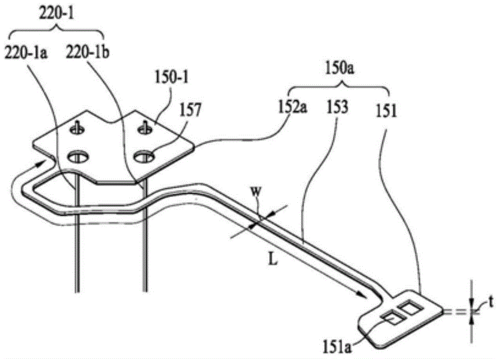
第一至第四上弹性构件部分150-1至150-4中的每一个150a或150b可以包含与线筒110耦接的第一内框架151、与壳体140耦接的第1-1外框架152a或152b,以及将第一内框架151与第1-1外框架152a或152b连接的第一框架连接部分153。Each of the first to fourth upper elastic member parts 150-1 to 150-4 150a or 150b may include a first
第一至第四上弹性构件部分150-1至150-4中的每一个的第一框架151可以与线筒110以及弹性构件接触部184-1至184-4中的对应接触部耦接。The
如图3所示例性示出,如果线筒110的第二突起112的上表面112a为平坦,第一内框架151可以位于线筒110的第二突起112的上表面112a上,然后使用粘合部件固定。As exemplarily shown in FIG. 3, if the
在另一实施例中,与图3不同,如果支承突出部(未示出)形成在上表面112a上,支承突出部可以插入到在第一内框架151上形成的通孔151a中,并且然后通过热熔合或使用诸如环氧树脂的粘合部件来固定。In another embodiment, unlike FIG. 3 , if the support protrusions (not shown) are formed on the
第1-1外框架152a或152b可以与壳体140耦接并连接至支承构件220。The 1-1st
第一框架连接部分153可以将第一内框架151和第1-1外框架152a或152b连接。尽管第1-1外框架152b具有与将第1-1外框架152a分割所获两个部分中的任一部分相同的形状,但是本发明不限于此。在另一实施例中,第1-1外框架152a可以分成两个部分,并且该两个部分可以具有与第1-1外框架152b相同的形状并且在两横侧对称设置。The first
第一框架连接部分153可以弯折至少一次并且可以形成具有指定形状的图案。通过第一框架连接部分153的位置改变和精细变形,线筒110在与光轴平行的第一方向上的提高和/或降低操作可以被弹性的支承。The first
壳体140的第一上支承突出部143可以将上弹性构件150的第1-1外框架152a和152b(如图9中所示例性示出)与壳体140耦接并固定至壳体140。The first
根据本实施例,与壳体140的第一上支承突出部143耦接的通孔157可以形成在第1-1外框架152a和152b上。壳体140的第一上支承突出部143和通孔157可以通过热熔合固定或使用诸如环氧树脂的粘合部件来固定。According to the present embodiment, through
在第一内框架151与线筒110耦接且第1-1外框架152a和152b与壳体140耦接之后,可以将电力例如不同极性的电力施加给第一位置传感器170的四个销(pins)中的两个销,并且,如图7所例示,可以通过在传感器基板180的弹性构件接触部184-1至184-4与第一内框架151之间进行诸如焊接的导电连接CP11、CP12、CP13和CP14来输出来自其余两个销的感测信号。例如,为了接收不同极性的电力并输出不同极性的感测信号,上弹性构件150包括四个上弹性件,即第一至第四上弹性件部分150-1至150-4。After the first
第一至第四上弹性件部分150-1至150-4可以通过支承构件220连接至电路板250。The first to fourth upper elastic parts 150 - 1 to 150 - 4 may be connected to the
例如,第一上弹性构件部分150-1可以通过第1-1支承构件220-1a和第1-2支承构件220-1b中的至少一个连接至电路板250,第二上弹性构件部分150-2可以通过第二支承构件220-2连接至电路板250,第三上弹性构件部分150-3可以通过第3-1支承构件220-3a和第3-2支承构件220-3b中的至少一个连接至电路板250,第四上弹性构件部分150-4可以通过第四支承构件220-4连接至电路板250。因此,第一位置传感器170可以通过支承构件220和上弹性构件150从电路板250接收电力或者将从第一位置传感器170输出的感测信号提供给电路板250。For example, the first upper elastic member portion 150-1 may be connected to the
下弹性构件160可以包括彼此电分离的第一下弹性构件部分160-1和第二下弹性构件部分160-2。第一线圈120可以通过第一下弹性构件部分160-1和第二下弹性构件部分160-2连接至支承构件220。The lower
第一下弹性构件部分160-1和第二下弹性构件部分160-2中的每一个可以包含一个或多个第二内框架161-1和161-2、一个或多个第二外框架162-1和162-2以及一个或多个第二框架连接部分163-1、163-2和163-3。Each of the first lower elastic member portion 160-1 and the second lower elastic member portion 160-2 may include one or more second inner frames 161-1 and 161-2, one or more second outer frames 162 -1 and 162-2 and one or more second frame connecting parts 163-1, 163-2 and 163-3.
第二内框架161-1和161-2可以与线筒110耦接,并且,第二外框架162-1和162-2可以与壳体140耦接。The second inner frames 161 - 1 and 161 - 2 may be coupled with the
第2-1框架连接部分163-1可以将第二内框架161-1与第二外框架162-1连接,第2-2框架连接部分163-2可以将该两个第二外框架162-1和162-2连接,第2-3框架连接部分163-3可以将第二内框架161-2和第二外框架162-2连接。The 2-1 frame connecting part 163-1 can connect the second inner frame 161-1 with the second outer frame 162-1, and the 2-2 frame connecting part 163-2 can connect the two second outer frames 162- 1 and 162-2 are connected, and the 2-3 frame connecting part 163-3 can connect the second inner frame 161-2 and the second outer frame 162-2.
另外,第一下弹性构件部分160-1可以另外包含第一线圈框架164-1,第二下弹性构件部分160-2可以另外包含第二线圈框架164-2。In addition, the first lower elastic member portion 160-1 may additionally include a first coil frame 164-1, and the second lower elastic member portion 160-2 may additionally include a second coil frame 164-2.
参看图9,第一线圈120的两端可以通过诸如焊料的导电连接部件导电连接至第一线圈框架164-1和第二线圈框架164-2。Referring to FIG. 9, both ends of the
第一下弹性构件部分160-1和第二下弹性构件部分160-2可以接收电力例如不同极性的电力,并将所接收的电力传输给第一线圈120。例如,为了接收不同极性的电力并将所接收的电力传输给第一线圈120,下弹性构件160可以包括两个下弹性构件,即第一下弹性构件部分160-1和第二下弹性构件部分160-2。The first lower elastic member part 160 - 1 and the second lower elastic member part 160 - 2 may receive power such as power of different polarities, and transmit the received power to the
另外,第一下弹性构件部分160-1和第二下弹性构件部分160-2中的每一个可以另外包含第2-4框架连接部分163-4。第2-4框架连接部分163-4可以将线圈框架164与第二内框架161-2连接。In addition, each of the first lower elastic member portion 160-1 and the second lower elastic member portion 160-2 may additionally include a 2-4th frame connecting portion 163-4. The 2-4th frame connecting portion 163-4 may connect the coil frame 164 with the second inner frame 161-2.
第2-1至第2-4框架连接部分163-1、163-2、163-3和163-4中的至少一个可以弯折至少一次并且形成具有指定形状的图案。具体地,通过第2-1框架连接部分163-1和第2-3框架连接部分163-3的位置变化和精细变形,线筒110在与光轴平行的第一方向上的升高和/或降低操作可以被弹性的支承。At least one of the 2-1st to 2-4th frame connecting parts 163-1, 163-2, 163-3, and 163-4 may be bent at least once and form a pattern having a designated shape. Specifically, through the positional change and fine deformation of the 2-1st frame connecting portion 163-1 and the 2-3rd frame connecting portion 163-3, the
根据一个实施例,第一下弹性构件部分160-1和第二下弹性构件部分160-2中的每一个可以另外包含弯折部165。According to one embodiment, each of the first lower elastic member portion 160 - 1 and the second lower elastic member portion 160 - 2 may additionally include a
第一下弹性构件部分160-1和第二下弹性构件部分160-2中的弯折部165可以从第2-2框架连接部分163-2在第一方向上朝上弹性构件150弯折。The
上弹性构件150可以另外包含分别彼此电分离的第五上弹性构件部分150-5和第六上弹性构件部分150-6。第一至第六上弹性构件部分150-1至150-6可以彼此电分离。The upper
第五上弹性构件部分150-5和第六上弹性构件部分150-6中的每一个可以包含连接框架154和第1-2外框架155。第五上弹性构件部分150-5和第六上弹性构件部分150-6的连接框架154可以在第一方向上延伸并且可以连接至下弹性构件部分160-1和160-2的弯折部165。Each of the fifth upper elastic member part 150 - 5 and the sixth upper elastic member part 150 - 6 may include a
第1-2外框架155可以在与第一方向垂直的方向上从连接框架154弯折,与壳体140耦接并连接至支承构件220。The 1-2
例如,第五上弹性构件150-5可以连接至第五支承构件220-5,第六上弹性构件150-6可以连接至第六支承构件220-6。此处,第一下弹性构件部分160-1和第二下弹性构件部分160-2的弯折部165以及第五上弹性构件部分150-5和第六上弹性构件部分150-6的连接框架154和第1-2外框架155可以一体形成。如上所述,第一下弹性构件部分160-1和第二下弹性构件部分160-2中的每一个和第五上弹性构件部分150-5和第六上弹性构件部分150-6中的每一个可以具有朝第一方向弯折的部分165或154。For example, the fifth upper elastic member 150-5 may be connected to the fifth support member 220-5, and the sixth upper elastic member 150-6 may be connected to the sixth support member 220-6. Here, the
以与第1-1外框架152b相同的方式,第1-2外框架155可以包含通孔。In the same manner as the 1-1st outer frame 152b, the 1-2nd
根据一个实施例,第一至第六上弹性构件部分150-1至150-6的第1-1外框架152b可以设置为在对角方向彼此相对,第1-2外框架155可以设置为在对角方向彼此相对。According to one embodiment, the 1-1st outer frames 152b of the first to sixth upper elastic member parts 150-1 to 150-6 may be arranged to be opposite to each other in a diagonal direction, and the 1-2th
应理解,第一下弹性构件部分160-1和第二下弹性构件部分160-2通过与支承构件220连接的第五上弹性构件部分150-5和第六上弹性构件部分150-6从电路板250接收电力,并将所接收的电力提供给第一线圈120。也就是说,第一下弹性构件部分160-1可以通过第六上弹性构件部分160-6和第六支承构件220-6连接至电路板250,第二下弹性构件部分160-2可以通过第五上弹性构件部分160-5和第五支承构件220-5连接至电路板250。It should be understood that the first lower elastic member portion 160-1 and the second lower elastic member portion 160-2 are removed from the electrical circuit through the fifth upper elastic member portion 150-5 and the sixth upper elastic member portion 150-6 connected to the
尽管实施例描述可上弹性构件150和下弹性构件160被分成多个上弹性构件和下弹性构件,但是在另一实施例中上弹性构件150和下弹性构件160可以不被分割。Although the embodiment describes that the upper and lower
线筒110的第一下支承突出部可以将下弹性构件160的第二内框架161-1和161-2与线筒110耦接并固定到线筒110。壳体140的第二支承突出部145可以将下弹性构件160的第二外框架162-1和162-2与壳体140耦接并固定到壳体140。The first lower supporting protrusions of the
参考图9,与线筒110的第一下支承突出部耦接的通孔161a可以形成在第一下弹性构件部分160-1和第二下弹性构件部分160-2的第二内框架161-1和161-2上。此处,线筒110的第一下支承突出部和通孔161a可以通过热熔合或使用诸如环氧树脂的粘合部件来固定。Referring to FIG. 9 , a through
另外,与壳体140的第二下支承突出部145耦接的通孔162a可以形成在第一下弹性构件部分160-1和第二下弹性构件部分160-2的第二外框架162-1和121-2上。此处,壳体140的第二下支承突出部145和通孔162a可以通过热熔合或使用诸如环氧树脂的粘合部件来固定。In addition, a through
上述上弹性构件150和下弹性构件160可以设置为片簧(leaf spring),但是对于上弹性构件150和下弹性构件160的材料本发明不做限制。The above-mentioned upper
可以使用两个相互电分离的上弹性构件150给第一位置传感器170供应电力,可以使用另外两个相互电分离的上弹性构件150将从第一位置传感器170输出的感测信号传输给电路板250,并且,可以使用两个相互电分离的下弹性构件160给第一线圈120供应电力。但是,本发明不限于此。The
在另一实施例中,上弹性构件150的功能和下弹性构件160的功能可以互换。也就是说,可以使用两个相互电分离的上弹性构件来给第一线圈120供应电力,可以使用两个相互电分离(conductively separated)的下弹性构件来给第一位置传感器170供应电力,并且,可以使用另外两个相互电分离的下弹性构件来将从第一位置传感器170输出的感测信号传输给电路板250。尽管此类结构图中未示出,可以通过图示内容易于想到。In another embodiment, the function of the upper
支承构件220可以分别设置在壳体140的第二侧部分142上。例如,两个支承构件220可以设置在四个第二侧部分142中的每一个上。The
或者,在壳体140的四个第二侧部分142中,可以将一个支承构件220设置在两个第二侧部分142中的每一个上,并且,可以将两个支承构件220设置在其余两个第二侧部分142的每一个上。Alternatively, in the four
另外,在另一实施例中,支承构件220可以是在壳体140的第一侧部分141上设置的片簧。In addition, in another embodiment, the
支承构件220可以形成路径来传输第一位置传感器170和第一线圈120所需的电力并且形成路径来将从第一位置传感器170输出的感测信号提供给电路板250,如上所述。The
支承构件220可以实施为弹性支承构件,例如,片簧、螺旋弹簧、金属丝弹簧或悬挂线(suspension wire)。另外,在另一实施例中,支承构件220可以与上弹性构件150一体形成。The
接下来,将描述基部210、电路板250、第二线圈230和第二位置传感器240。Next, the
基部210可以具有与线筒110中空部和/或壳体140中空部对应的中空部,并且具有与盖部件300相符或对应的形状,例如矩形。The
图10是图1所示的基部210、第二线圈230、第二位置传感器240和电路板250的分解透视图。FIG. 10 is an exploded perspective view of the
基部210可以包含阶梯(staircase)211,在将盖部件300附接到基部210时可以将阶梯211涂覆以粘合剂。此处,阶梯211可以引导与其上部耦接的盖部件300,并且盖部件300的末端(distal end)可以与阶梯211表面接触。The base 210 may include a
基部210的阶梯211和盖部件300的末端可以通过粘合剂等来固定和密封。The
基部210可以与第一透镜驱动单元间隔开指定距离。具有与电路板250的具有端子251的区域对应大小的支承部分255可以形成在基部210的与电路板250端子251相对的表面上。支承部分255可以形成在基部210的外表面上而不设阶梯211,并且支承部分255可以支承形成有端子251的端子表面(terminal surface)253。The base 210 may be spaced apart from the first lens driving unit by a specified distance. A
基部210的拐角可以具有第二凹槽212。如果盖部件300的拐角具有突出形状,盖部件300的此类突起可以与基部210的第二凹陷212耦接。Corners of the base 210 may have
另外,可供设置第二位置传感器240的第二负载凹槽215-1和215-2可以设置在基部210的上表面上。In addition, second load grooves 215 - 1 and 215 - 2 where the
根据本实施例,第二位置传感器240的数量可以是两个,因此,可以提供两个第二负载凹槽215-1和215-2。两个第二位置传感器240-1和240-2中的每一个可以设置在第二负载凹槽215-1和215-2中的对应负载凹槽中,并且,第二位置传感器240-1和240-2可以感测壳体140在第二方向和第三方向上的移动程度。由将各个第二负载凹槽215-1和215-2与基部210中心连接的虚拟线所形成的角度可以形成为直角,但是本发明不限于此。According to the present embodiment, the number of the
另外,用于安装滤光器的负载部分(未示出)可以形成在基部210的下表面上。此类滤光器可以是IR截止滤光器。但是,本发明不限于此,并且该滤光器可以设置在基部210下方单独设置的传感器固持器上。另外,如下文将要描述,安装有图像传感器的电路板250可以设置在基部210的下表面上,并且该摄像头模块可以包含根据本实施例所述的透镜移动装置100以及安装有所述图像传感器的电路板250。In addition, a load portion (not shown) for mounting the filter may be formed on the lower surface of the
第二线圈230可以设置在电路板250上,第二位置传感器240可以设置在电路板250下方。第二位置传感器240可以感测壳体140在与光轴垂直的方向上相对于基部210的位移。The
第二位置传感器240可以包括两个传感器240-1和240-2,该两个传感器240-1和240-2可以设置为彼此垂直以感测在与光轴垂直的方向(x轴方向和/或y轴方向)上的壳体140的位移。The
第二位置传感器240、第二线圈230和第二磁体130可以设置成沿同一轴线对齐,但是本发明不限于此。The
电路板250可以设置在基部210的上表面上,并且具有与线筒110中空部、壳体140中空部和/或基部210中空部对应的中空部。电路板250可以具有与基部210上表面形状相符或对应形状的形状,例如矩形形状。The
电路板250可以具有从电路板250上表面弯折的至少一个端子表面253,使得用于从外部接收电信号的多个端子251或销形成在端子表面253上。The
第二线圈230可以包括穿过电路部件231拐角部分的通孔230a。支承构件220可以穿过电路部件231的通孔230a并连接至电路板250。The
第二线圈230可以设置在电路板250上以与固定到壳体140的第二磁体130相对。The
尽管图10中例示了将第二线圈230形成在独立于电路板250设置的电路部件231上,但是本发明不限于此,并且,根据另一实施例,可以使用在电路板250上形成的电路图案来实施第二线圈230。Although it is illustrated in FIG. 10 that the
可以将四个第二线圈230安装在电路部件231上,但是本发明不限于此。也就是说,可以只安装两个第二线圈,包含用于第二方向的一个第二线圈和用于第三方向的一个第二线圈,或者,可以安装四个或四个以上的第二线圈。Four
或者,第二线圈230可以通过将导线缠绕成圆环状线圈形状或形成为精细图案(fine pattern,FP)线圈形状来形成第二线圈230,并且然后第二线圈230可以导电连接至电路板250。Alternatively, the
如上所述,可以通过设置为彼此相对的第二磁体130与第二线圈230之间的相互作用来在第二方向和/或第三方向上移动壳体140,来执行手抖补偿。As described above, hand shake compensation may be performed by moving the
第二位置传感器240可以包括:第一传感器240-1,用于感测第一透镜移动单元在与光轴(z轴)垂直的x轴方向上的位移;以及第二传感器240-2,用于感测第一透镜移动单元在y轴方向上的位移。The
第二位置传感器240可以设置为穿过电路板250与第二线圈230中心对齐,但是本发明不限于此。The
尽管第二位置传感器240可以是霍尔传感器(Hall sensor),但是可以使用能够感测磁场强度的任何传感器来作为第二位置传感器240。Although the
电路板250可以包括能够与支承构件220耦接的连接器区域250a1和250a2。支承构件220可以通过焊接与电路板250的连接器区域250a1和250a2耦接,并且因此与在电路板250上形成的电路图案导电连接。例如,连接器区域250a1和250a2形成为穿过电路板250的通孔,但不限于此。在另一实施例中,连接器区域250a1和250a2形成为没有穿过电路板250的连接焊盘。The
电路板250可以另外包含与基部210的第二上支承突出部217耦接的通孔250b。电路板250可以另外包含端子251。端子表面253可以通过弯折形成在电路板250上。一个或多个端子251可以安装在电路板250的端子表面253上。The
根据本实施例,通过在端子表面253上安装的端子251,电路板250可以接收外部电力,并将所接收的电力供应给第一线圈120和第二线圈230以及第一传感器170和第二传感器240,并将从第一位置传感器170和第二位置传感器240输出的感测信号输出到外部。在端子表面253上形成的端子251的数量可以根据所需控制的元件的种类和这些元件的数量来增加或减少。According to the present embodiment, through the
根据本实施例所述,电路板250可以是FPCB,但是本发明不限于此。在电路板250上形成的端子251可以直接形成在基部210的表面上。According to this embodiment, the
如上所述,电路板250可以给第一线圈120和第二线圈230以及第一位置传感器170供应所需电力,并且将来自第一位置传感器170的感测信号和从第二位置传感器240输出的感测信号传输给摄像头模块的控制器。As described above, the
根据上述实施例所述的透镜移动装置可以用在例如摄像头模块等各个领域中。例如,摄像头模块可以应用于移动装置诸如便携型终端中。The lens moving device according to the above-described embodiments can be used in various fields such as a camera module. For example, the camera module may be applied to a mobile device such as a portable terminal.
根据本实施例所述的摄像头模块可以包括:与线筒110耦接的透镜镜筒;图像传感器(未示出);图像传感器,该图像传感器可以连接至电路板250并具有图像传感器;以及光学系统。根据本实施例所述的摄像头模块可以另外包括IR截止滤光器(未示出),用于截止入射到图像传感器上的红外波长范围的光。The camera module according to the present embodiment may include: a lens barrel coupled to the
另外,该光学系统可以包含至少一个透镜以用于将图像传输给该图像传感器。可以将执行自动聚焦功能和手抖补偿功能两种功能的致动器模块安装在该光学系统中。根据本实施例所述的透镜移动装置可以用作执行自动聚焦功能和手抖补偿功能两种功能的致动器模块。Additionally, the optical system may contain at least one lens for transmitting an image to the image sensor. An actuator module that performs both functions of an auto-focus function and a hand-shake compensation function can be installed in this optical system. The lens moving device according to the present embodiment can be used as an actuator module that performs both functions of an auto-focus function and a hand-shake compensation function.
基部210可以执行传感器固持器的功能以保护该图像传感器,但是本发明不限于此。也就是说,可以将独立的传感器固持器设置在基部210下方因此执行图像传感器保护功能。The base 210 may perform the function of a sensor holder to protect the image sensor, but the present invention is not limited thereto. That is, a separate sensor holder may be provided under the
下文将描述透镜驱动装置100的稳定的反馈控制。此处,该稳定的反馈控制称作用于防止振动的AF驱动控制和/或OIS驱动控制。The stable feedback control of the
为了执行稳定的反馈控制,需要二级谐振频率(secondary resonant frequency)或较高阶谐振频率(higher-order resonant frequency)与AF驱动控制段和/或OIS驱动控制段相偏离的设计。另外,需要一级谐振频率(primary resonant frequency)位于AF驱动控制段和/或OIS驱动控制段内的设计。In order to perform stable feedback control, a design in which the secondary resonant frequency or higher-order resonant frequency deviates from the AF driving control section and/or the OIS driving control section is required. In addition, a design is required in which the primary resonant frequency is located within the AF drive control section and/or the OIS drive control section.
例如,在用于移动终端的摄像头模块中,用于AF反馈控制和/或OIS反馈控制的频率响应特性的控制段可以是200Hz或200Hz以下的区段,并且,为了执行稳定的AF反馈控制和/或OIS反馈控制,将频率响应特性的二级谐振频率设计为超过200Hz。For example, in a camera module for a mobile terminal, a control section for frequency response characteristics of AF feedback control and/or OIS feedback control may be a section of 200 Hz or less, and, in order to perform stable AF feedback control and / or OIS feedback control, the secondary resonance frequency of the frequency response characteristic is designed to exceed 200Hz.
首先,将描述关于AF反馈驱动控制的传递函数、谐振频率与上弹性构件和下弹性构件的厚度和宽度之间的关系。First, the relationship between the transfer function, the resonance frequency, and the thickness and width of the upper and lower elastic members with respect to the AF feedback drive control will be described.
用于AF反馈驱动控制的传递函数H可以定义为以下方程式1。The transfer function H for AF feedback drive control can be defined as
[方程式1][Equation 1]
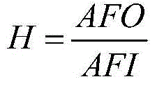
此处,AFO可以是第一位置传感器170的感测信号或反馈信号,AFI可以是供应给第一线圈120的输入信号例如供应电流。Here, AFO may be a sensing signal or a feedback signal of the
移动单元的位移可以根据供应给第一线圈120的输入信号AFI来确定,第一位置传感器170的输出AFO可以根据该移动单元的位移来确定。The displacement of the moving unit may be determined according to the input signal AFI supplied to the
传递函数H可以是第一位置传感器170的输出信号AFO与供应给第一线圈120的输入信号AFI之比。The transfer function H may be the ratio of the output signal AFO of the
这里,比例积分微分(PID)控制可以在传递函数H中得到反映。例如,该传递函数H可以包含用于PID控制的极点和零点。Here, proportional-integral-derivative (PID) control can be reflected in the transfer function H. For example, the transfer function H may contain poles and zeros for PID control.
通过PID控制,在低频范围内的增益可以得到调整或随着产品不同而具有不同频率特性的透镜移动装置可以被校正以在相同位置具有相同增益值。能够使得随产品不同而具有不同频率特性的透镜移动装置在相同位置具有相同增益值的校正被称作环路增益(loop gain)。通过环路增益,可以减少透镜移动装置因为产品不同而产生的色散(dispersion)。Through PID control, the gain in the low frequency range can be adjusted or the lens moving device having different frequency characteristics depending on the product can be corrected to have the same gain value at the same position. Correction that enables lens shifting devices having different frequency characteristics depending on the product to have the same gain value at the same position is called a loop gain. Through the loop gain, the dispersion caused by the different products of the lens moving device can be reduced.
PID控制可以由第一位置传感器170执行。这里,第一位置传感器170可以包含能够执行PID控制的驱动器。PID control may be performed by the
或者,在传递函数H中不会反映PID控制。在这种情况下,可以通过在该摄像头模块上安装的驱动器来执行PID控制,并且,第一位置传感器170可以是单个霍尔传感器。Alternatively, the PID control is not reflected in the transfer function H. In this case, PID control may be performed by a driver installed on the camera module, and the
根据传递函数H的增益的频率响应特性的谐振频率与移动单元的重量的根值(root value)成反比,并且与上弹性构件和下弹性构件的弹性模量的根值成正比。The resonance frequency of the frequency response characteristic according to the gain of the transfer function H is inversely proportional to the root value of the weight of the mobile unit, and proportional to the root value of the elastic moduli of the upper and lower elastic members.
根据传递函数H增益的频率响应特性的一级谐振频率可以指在第一方向(例如,z轴方向)上的谐振频率,二级谐振频率和三级谐振频率可以指示在第二方向和第三方向(例如,x轴方向和y轴方向)上移动(shift)或倾斜(tilt)的谐振频率。The first-order resonance frequency according to the frequency response characteristic of the transfer function H-gain may refer to the resonance frequency in the first direction (eg, the z-axis direction), and the second-order resonance frequency and the third-order resonance frequency may indicate the second and third A resonant frequency that shifts or tilts in a direction (eg, the x-axis direction and the y-axis direction).
为了执行稳定的AF反馈控制,根据透镜移动装置100的AF反馈驱动控制的传递函数H的增益的频率响应特性的一级谐振频率可以是30Hz至200Hz的范围中。Hz指的是频率单位赫兹。In order to perform stable AF feedback control, the first-order resonance frequency of the frequency response characteristic according to the gain of the transfer function H of the AF feedback drive control of the
图11是示出根据一个实施例所述的传递函数H的增益的频率响应特性的一级谐振频率f1和二级谐振频率f2的曲线图。上述PID控制可以在图11中所示的传递函数H得到反映。FIG. 11 is a graph showing the first-order resonance frequency f1 and the second-order resonance frequency f2 of the frequency response characteristic of the gain of the transfer function H according to one embodiment. The above-described PID control can be reflected in the transfer function H shown in FIG. 11 .
参考图11,根据传递函数H的增益的频率响应特性的一级谐振频率f1可以具有第一频率域S1,第一频率域S1可以是处于30Hz至200Hz范围的区域。11 , the first-order resonance frequency f1 according to the frequency response characteristic of the gain of the transfer function H may have a first frequency domain S1 which may be a region in the range of 30 Hz to 200 Hz.
另外,为了执行更稳定的AF反馈驱动控制,一级谐振频率f1可以具有第二频率域Q1,第二频率域Q1可以是处于40Hz至120Hz范围的区域。In addition, in order to perform more stable AF feedback drive control, the primary resonance frequency f1 may have a second frequency domain Q1, which may be a region in the range of 40 Hz to 120 Hz.
为了确保通过PID控制能够在低频域内获得足够增益,该一级谐振频率可以具有第三频率域Q2,并且该第三频率域Q2可以是50Hz至100Hz范围的区域。In order to ensure that sufficient gain can be obtained in the low frequency domain through the PID control, the first-order resonance frequency may have a third frequency domain Q2, and the third frequency domain Q2 may be a region ranging from 50 Hz to 100 Hz.
另外,为了执行稳定的AF反馈驱动控制,根据传递函数H的增益的频率响应特性的二级谐振频率f2可以具有第四频率域(frequency domain)S2,并且该第四频率域S2可以具有超过200Hz的区域。In addition, in order to perform stable AF feedback drive control, the secondary resonance frequency f2 according to the frequency response characteristic of the gain of the transfer function H may have a fourth frequency domain (frequency domain) S2, and the fourth frequency domain S2 may have more than 200 Hz Area.
也就是说,根据第一位置传感器170输出信号与施加给第一线圈120的输入信号之比的增益的频率响应特性的二级谐振频率f2可以超过200Hz。That is, the secondary resonance frequency f2 of the frequency response characteristic of the gain according to the ratio of the output signal of the
例如,为了执行更稳定的AF反馈驱动控制,根据传递函数H的增益的频率响应特性的二级谐振频率f2可以具有第五频率域Q3,并且该第五频率域Q3可以是等于或大于250Hz的区域。For example, in order to perform more stable AF feedback drive control, the secondary resonance frequency f2 according to the frequency response characteristic of the gain of the transfer function H may have a fifth frequency domain Q3, and the fifth frequency domain Q3 may be equal to or greater than 250 Hz area.
在AF反馈控制期间根据传递函数H的增益的频率响应特性的增益裕度(gainmargin)和相位裕度(phase margin)可以用作关于反馈稳定性的指标。相位裕度指的是增益为0dB时的位置处的相位,增益裕度指的是相位为0°时位置的增益值。The gain margin and the phase margin according to the frequency response characteristic of the gain of the transfer function H during the AF feedback control can be used as an index on feedback stability. Phase margin refers to the phase at the position when the gain is 0dB, and gain margin refers to the gain value at the position when the phase is 0°.
为了执行PID控制,在根据传递函数H的增益的频率响应特性中,与0dB增益对应的频率可以是60Hz至200Hz。In order to perform the PID control, in the frequency response characteristic according to the gain of the transfer function H, the frequency corresponding to the 0 dB gain may be 60 Hz to 200 Hz.
根据传递函数H的增益的频率响应特性的一级谐振频率可以通过上弹性构件150和下弹性构件160在第一方向(例如z轴方向)上的弹性模量(the moduli of elasticity)和AF移动单元的重量来确定。该AF移动单元的重量可以包含透镜镜筒的重量的透镜的重量。The first-order resonance frequency according to the frequency response characteristic of the gain of the transfer function H may be shifted by the moduli of elasticity and AF of the upper
根据传递函数H的增益的频率响应特性的二级谐振频率可以通过上弹性构件150和下弹性构件160在第二方向和第三方向(例如x轴方向和y轴方向)中的弹性模量来确定。The secondary resonance frequency according to the frequency response characteristic of the gain of the transfer function H may be determined by the elastic moduli of the upper
例如,该AF移动单元可以包含线筒110以及在线筒110上安装的能与线筒110一起移动的元件。例如,该AF移动单元可以包含至少该线筒110和在该线筒110上安装的透镜(未示出),并且根据实施例可以另外包含第一线圈120、感测基板180、第一位置传感器170和第一磁体190中的至少一个。For example, the AF moving unit may include the
上弹性构件150和下弹性构件160在第一方向上的弹性模量可以与上弹性构件150和下弹性构件160的厚度的立方成正比,与上弹性构件150和下弹性构件160的宽度成正比,与上弹性构件150和下弹性构件160的长度成反比。The elastic modulus of the upper
根据本实施例所述的上弹性构件150和下弹性构件160可以是片簧,并且,即使上弹性构件150和下弹性构件160是金属丝弹簧或线圈弹簧,在上弹性构件150和下弹性构件160的弹性模量与上弹性构件150和下弹性构件160的宽度和厚度之间的关系也可以与本实施例所述相同。The upper
另一方面,上弹性构件150和下弹性构件160在第二方向和第三方向上的弹性模量可以与上弹性构件150和下弹性构件160的宽度的立方成正比(directly proportional),与上弹性构件150和下弹性构件160的厚度成正比,与上弹性构件150和下弹性构件160的长度成反比。On the other hand, the elastic moduli of the upper
图12是图9所示第一上弹性构件150-1的放大图。FIG. 12 is an enlarged view of the first upper elastic member 150 - 1 shown in FIG. 9 .
参见图12,第一上弹性构件150-1在z轴方向上的弹性模量可以与第一上弹性构件150-1的厚度t的立方成正比,与第一上弹性构件150-1的宽度W成正比,与第一上弹性构件150-1的长度L成反比。Referring to FIG. 12 , the elastic modulus of the first upper elastic member 150-1 in the z-axis direction may be proportional to the cube of the thickness t of the first upper elastic member 150-1, and the width of the first upper elastic member 150-1 W is proportional to and inversely proportional to the length L of the first upper elastic member 150-1.
第一上弹性构件150-1的宽度、长度和厚度可以是第一上弹性构件150-1的除了与线筒110和壳体140固定的两端之外的弹性变形部分的宽度、长度和厚度。The width, length and thickness of the first upper elastic member 150-1 may be the width, length and thickness of the elastically deformed portion of the first upper elastic member 150-1 except for both ends fixed to the
例如,第一上弹性构件150-1的宽度W可以是第一框架连接部分153的宽度,第一上弹性构件150-1的长度L可以是第一框架连接部分153的长度。For example, the width W of the first upper elastic member 150 - 1 may be the width of the first
另一方面,第一上弹性构件150-1在x轴和y轴方向上的弹性模量可以与第一上弹性构件150-1的宽度W的立方成正比,与第一上弹性构件150-1的厚度成正比,与第一上弹性构件150-1的长度成反比。On the other hand, the elastic modulus of the first upper elastic member 150-1 in the x-axis and y-axis directions may be proportional to the cube of the width W of the first upper elastic member 150-1, which is proportional to the cube of the width W of the first upper elastic member 150-1. The thickness of 1 is proportional to the length of the first upper elastic member 150-1.
例如,当根据透镜移动装置100的传递函数H的频率响应特性的一级谐振频率是60Hz时,该AF移动单元的重量是0.3g,上弹性构件150和下弹性构件160的弹性模量K是44N/m,为了形成200Hz的二级谐振频率,上弹性构件150和下弹性构件160在第二方向和第三方向上的弹性模量K需要为约500N/m。此处,上弹性构件150和下弹性构件160在第二方向和第三方向上的弹性模量K可以是上弹性构件150和下弹性构件160在第一方向上的弹性模量K的约11倍。For example, when the first-order resonance frequency according to the frequency response characteristic of the transfer function H of the
另外,为了在相同条件下形成二级谐振频率300Hz,上弹性构件150和下弹性构件160在第二方向和第三方向上的弹性模量K需要为约1100N/m。此处,上弹性构件150和下弹性构件160在第二方向和第三方向上的弹性模量K可以是上弹性构件150和下弹性构件160在第一方向上的弹性模量K的约25倍。In addition, in order to form the secondary resonance frequency of 300 Hz under the same conditions, the elastic moduli K of the upper
另外,例如,为了在根据透镜移动装置100的传递函数H的增益的频率响应特性中形成30Hz至200Hz的一级谐振频率和超过200Hz的二级谐振频率,透镜移动装置100的上弹性构件150和下弹性构件160的宽度可以是上弹性构件150和下弹性构件160的厚度t的预定倍或预定倍以上。此处,该预定倍可以是2倍至3倍。In addition, for example, in order to form a first-order resonance frequency of 30 Hz to 200 Hz and a second-order resonance frequency exceeding 200 Hz in the frequency response characteristic according to the gain of the transfer function H of the
例如,上弹性构件150和下弹性构件160的宽度可以是上弹性构件150和下弹性构件160的厚度t的2倍至3倍。For example, the width of the upper
例如,当上弹性构件150和下弹性构件160的厚度是40μm并且根据透镜移动装置100的传递函数H的增益的频率响应特性的一级谐振频率为60Hz时,为了形成超过200Hz的二级谐振频率,上弹性构件150和下弹性构件160可以具有至少90μm的宽度。For example, when the thickness of the upper
另外,当上弹性构件150和下弹性构件160的厚度是40μm并且根据透镜移动装置100的传递函数H的增益的频率响应特性的一级谐振频率为60Hz时,为了形成超过300Hz的二级谐振频率,上弹性构件150和下弹性构件160可以具有至少116μm的宽度。In addition, when the thickness of the upper
根据本实施例所述的上弹性构件150和下弹性构件160的厚度可以是30μm至50μm。The thickness of the upper
为了在根据透镜移动装置100的传递函数H的增益的频率响应特性中形成30Hz至200Hz的一级谐振频率并形成超过200Hz的二级谐振频率,根据本实施例所述的上弹性构件150和下弹性构件160的宽度可以等于或大于参考宽度。此处,该参考宽度可以是60μm至100μm。In order to form a first-order resonance frequency of 30 Hz to 200 Hz and a second-order resonance frequency exceeding 200 Hz in the frequency response characteristic according to the gain of the transfer function H of the
图13是示出根据一个实施例所述的透镜移动装置的AF反馈驱动控制的传递函数H的基于增益的频率响应特性和基于相位的频率响应特性的曲线图。13 is a graph showing a gain-based frequency response characteristic and a phase-based frequency response characteristic of the transfer function H of the AF feedback drive control of the lens moving device according to one embodiment.
参看图13,应理解,在根据AF反馈驱动控制的传递函数H的增益的频率响应特性中,一级谐振频率f1为100Hz,二级谐振频率f2为420Hz。13 , it should be understood that in the frequency response characteristics according to the gain of the transfer function H of the AF feedback drive control, the primary resonance frequency f1 is 100 Hz, and the secondary resonance frequency f2 is 420 Hz.
为了执行稳定的AF反馈驱动控制,在基于增益的频率响应特性中,增益裕度需要为约12dB或12dB以上,相位裕度需要为45°或45°以上。In order to perform stable AF feedback drive control, in gain-based frequency response characteristics, the gain margin needs to be about 12 dB or more, and the phase margin needs to be 45° or more.
从图13可以看出,增益裕度GM为18dB,相位裕度PM为约66°,由此本实施例可以确保AF驱动控制的稳定性。As can be seen from FIG. 13 , the gain margin GM is 18 dB, and the phase margin PM is about 66°, whereby the present embodiment can ensure the stability of the AF drive control.
另外,通过在上弹性构件150和下弹性构件160、AF移动单元或固定单元上执行消振过程(damping process),可以降低谐振频率的增益的峰值。In addition, by performing a damping process on the upper
接下来,将描述用于OIS反馈驱动控制的传递函数、谐振频率和上弹性构件和下弹性构件的厚度和宽度相互间的关系。Next, the relationship between the transfer function, the resonance frequency, and the thicknesses and widths of the upper and lower elastic members for the OIS feedback drive control will be described.
用于OIS反馈驱动控制的传递函数HOIS可以定义为以下方程式2。The transfer function HOIS for the OIS feedback drive control can be defined as Equation 2 below.
[方程式2][Equation 2]
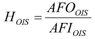
此处,AFOOIS可以是来自第二位置传感器240的输出信号,并且,AFIOIS可以是供应给第二线圈230的输入信号。Here, AFOOIS may be an output signal from the
例如,AFOOIS可以是来自第二位置传感器240-1的输出信号,并且,AFIOIS可以是供应给与第二位置传感器240-1对应的第二线圈230的输入信号。For example, AFOOIS may be an output signal from the second position sensor 240-1, and AFIOIS may be an input signal supplied to the
另外,例如,AFOOIS可以是来自第二位置传感器240-2的输出信号,并且,AFIOIS可以是供应给与第二位置传感器240-2对应的第二线圈230的输入信号。Also, for example, AFOOIS may be an output signal from the second position sensor 240-2, and AFIOIS may be an input signal supplied to the
用于在低频域的快速OIS反馈控制的PID控制可以在传递函数HOIS中得到反映,或者也可以不反映。例如,传递函数HOIS可以包含关于PID控制的极点和零点。The PID control for fast OIS feedback control in the low frequency domain may or may not be reflected in the transfer function HOIS. For example, the transfer function HOIS may contain poles and zeros for PID control.
PID控制可以由在该摄像头模块上安装的第二位置传感器240或驱动器来执行。例如,第二位置传感器240、240-1和240-2可以包含用于执行比例积分微分(PID)控制的驱动器。The PID control can be performed by the
OIS移动单元的位移可以基于供应给第二线圈230的输入信号AFIOIS来确定,第二位置传感器240的输出AFOOIS可以根据该OIS移动单元的位移来确定。传递函数HOIS可以是第二位置传感器240的输出信号AFOOIS与供应给第二线圈230的输入信号AFIOIS之比。The displacement of the OIS moving unit may be determined based on the input signal AFIOIS supplied to the
该OIS移动单元可以包含上述AF移动单元和在壳体140中安装的元件。例如,根据实施例,该OIS移动单元可以包含至少该AF移动单元和壳体140,并且可以另外包含第一磁体190和第二磁体130-1至130-4。The OIS moving unit may include the above-described AF moving unit and elements installed in the
根据传递函数HOIS的增益的频率响应特性的一级谐振频率指的是在第二方向和第三方向(例如,x轴方向和y轴方向)中的谐振频率,并且,二级谐振频率和三级谐振频率指的是在第一方向(例如,z轴方向)中移动或倾斜的谐振频率。The first-order resonance frequency according to the frequency response characteristic of the gain of the transfer function HOIS refers to the resonance frequencies in the second and third directions (for example, the x-axis direction and the y-axis direction), and the second-order resonance frequency and the third-order resonance frequency The stage resonant frequency refers to the resonant frequency that moves or tilts in a first direction (eg, the z-axis direction).
为了执行在第二方向和第三方向上的稳定的OIS反馈控制,根据透镜移动装置100的OIS反馈驱动控制的传递函数HOIS的增益的频率响应特性的一级谐振频率可以是处于30Hz至200Hz的范围。In order to perform stable OIS feedback control in the second and third directions, the first-order resonance frequency of the frequency response characteristic according to the gain of the transfer function HOIS of the OIS feedback drive control of the
也就是说,根据第二位置传感器240的输出信号与供应给第二线圈230的输入信号之比的增益的频率响应特性的一级谐振频率可以是30Hz至200Hz的范围。That is, the first-order resonance frequency of the frequency response characteristic of the gain according to the ratio of the output signal of the
例如,为了执行稳定的OIS反馈驱动控制,根据传递函数HOIS的增益的频率响应特性的一级谐振频率可以是40Hz至120Hz的范围。For example, in order to perform stable OIS feedback drive control, the first-order resonance frequency according to the frequency response characteristic of the gain of the transfer function HOIS may be in the range of 40 Hz to 120 Hz.
例如,为了执行更为稳定的OIS反馈驱动控制,根据传递函数HOIS的增益的频率响应特性的一级谐振频率可以是50Hz至100Hz的范围。For example, in order to perform more stable OIS feedback drive control, the first-order resonance frequency according to the frequency response characteristic of the gain of the transfer function HOIS may be in the range of 50 Hz to 100 Hz.
另外,为了执行稳定的OIS反馈驱动控制,根据传递函数HOIS的增益的频率响应特性的二级谐振频率可以超过200Hz。In addition, in order to perform stable OIS feedback drive control, the secondary resonance frequency according to the frequency response characteristic of the gain of the transfer function HOIS may exceed 200 Hz.
也就是说,根据第二位置传感器240的输出信号与施加给第二线圈230的输入信号之比的增益的频率响应特性的二级谐振频率可以超过200Hz。That is, the secondary resonance frequency of the frequency response characteristic of the gain according to the ratio of the output signal of the
例如,为了执行更为稳定的OIS反馈驱动控制,根据传递函数HOIS的增益的频率响应特性的二级谐振频率可以等于或大于250Hz。For example, in order to perform more stable OIS feedback drive control, the secondary resonance frequency of the frequency response characteristic according to the gain of the transfer function HOIS may be equal to or greater than 250 Hz.
为了确保在低频处的增益,在根据传递函数HOIS的增益的频率响应特性中,0dB增益处的频率可以是60Hz至200Hz。In order to secure the gain at low frequencies, in the frequency response characteristic of the gain according to the transfer function HOIS, the frequency at the 0 dB gain may be 60 Hz to 200 Hz.
总体上,在OIS反馈驱动期间所用的频率可以是20Hz或20Hz以下。通过将与根据传递函数HOIS增益的频率响应特性中的0dB增益处对应的频率设计为在OIS反馈驱动期间所用的频率的两倍或两倍以上,OIS特性可以被满足并且可以确保稳定的OIS反馈驱动。In general, the frequency used during OIS feedback drive may be 20 Hz or less. By designing the frequency corresponding to the 0 dB gain in the frequency response characteristic of the HOIS gain according to the transfer function to be twice or more the frequency used during the OIS feedback drive, the OIS characteristic can be satisfied and stable OIS feedback can be ensured drive.
因为如上所述透镜移动装置100的上弹性构件150和下弹性构件160的宽度是上弹性构件150和下弹性构件160的厚度t的预定倍或预定倍以上,所以根据传递函数HOIS增益的频率响应特性的一级谐振频率可以是30Hz至200Hz,二级谐振频率可以超过200Hz。Since the width of the upper
从以上描述可以看出,根据一个实施例所述的透镜移动装置100将上弹性构件150和下弹性构件160的宽度设计为上弹性构件150和下弹性构件160的厚度的预定倍或预定倍以上,并且因此可以执行稳定准确的AF反馈控制和OIS反馈控制。As can be seen from the above description, the
尽管参考本发明多个说明性实施例描述了本发明,但是应理解,本领域技术人员可以构思在本发明原理精神范围内的众多其他修改和实施例。更具体地,可以在说明书、附图和权利要求书范围内对主题组合布置的组成部分和/或布置做出各种变化和修改。除了在组成部分和/或布置中做出各种变化和修改之外,替代使用对于本领域技术人员也是一目了然的。Although the present invention has been described with reference to a number of illustrative embodiments thereof, it should be understood that numerous other modifications and embodiments can be devised by those skilled in the art that will fall within the spirit of the principles of this invention. More particularly, various changes and modifications may be made in the components and/or arrangements of the subject combination arrangement within the scope of the specification, drawings and claims. In addition to various changes and modifications in the component parts and/or arrangements, alternative uses will also be apparent to those skilled in the art.
Claims (19)
Priority Applications (1)
| Application Number | Priority Date | Filing Date | Title |
|---|---|---|---|
| CN202011010441.1A CN112198739B (en) | 2015-01-23 | 2016-01-25 | lens shifter |
Applications Claiming Priority (2)
| Application Number | Priority Date | Filing Date | Title |
|---|---|---|---|
| KR1020150011214A KR20160091053A (en) | 2015-01-23 | 2015-01-23 | Lens moving unit |
| KR10-2015-0011214 | 2015-01-23 |
Related Child Applications (1)
| Application Number | Title | Priority Date | Filing Date |
|---|---|---|---|
| CN202011010441.1A Division CN112198739B (en) | 2015-01-23 | 2016-01-25 | lens shifter |
Publications (2)
| Publication Number | Publication Date |
|---|---|
| CN105824168A CN105824168A (en) | 2016-08-03 |
| CN105824168B true CN105824168B (en) | 2020-10-23 |
Family
ID=56434446
Family Applications (2)
| Application Number | Title | Priority Date | Filing Date |
|---|---|---|---|
| CN201610049681.XA Active CN105824168B (en) | 2015-01-23 | 2016-01-25 | lens shifter |
| CN202011010441.1A Active CN112198739B (en) | 2015-01-23 | 2016-01-25 | lens shifter |
Family Applications After (1)
| Application Number | Title | Priority Date | Filing Date |
|---|---|---|---|
| CN202011010441.1A Active CN112198739B (en) | 2015-01-23 | 2016-01-25 | lens shifter |
Country Status (3)
| Country | Link |
|---|---|
| US (3) | US10216000B2 (en) |
| KR (3) | KR20160091053A (en) |
| CN (2) | CN105824168B (en) |
Families Citing this family (21)
| Publication number | Priority date | Publication date | Assignee | Title |
|---|---|---|---|---|
| US9791713B2 (en) * | 2014-07-24 | 2017-10-17 | Lg Innotek Co., Ltd. | Lens moving apparatus |
| KR20160091053A (en) * | 2015-01-23 | 2016-08-02 | 엘지이노텍 주식회사 | Lens moving unit |
| KR102311663B1 (en) | 2015-03-18 | 2021-10-13 | 엘지이노텍 주식회사 | A lens moving unit and a camera module including the same |
| KR102560790B1 (en) * | 2016-07-29 | 2023-07-28 | 엘지이노텍 주식회사 | Dual camera module and optical apparatus |
| KR101892811B1 (en) | 2016-09-08 | 2018-10-05 | 삼성전기주식회사 | Actuator of camera module |
| US11163211B2 (en) * | 2016-10-04 | 2021-11-02 | Samsung Electro-Mechanics Co., Ltd. | Camera module actuator |
| KR101804921B1 (en) * | 2016-10-20 | 2018-01-10 | (주) 엠디펄스 | Ois camera module |
| TWI649595B (en) * | 2017-02-08 | 2019-02-01 | 日商阿爾普士電氣股份有限公司 | Lens driving device |
| KR102130205B1 (en) * | 2017-05-29 | 2020-07-03 | 로무 가부시키가이샤 | Imaging device |
| KR102338925B1 (en) | 2017-06-27 | 2021-12-13 | 엘지이노텍 주식회사 | Camera module |
| KR102560085B1 (en) * | 2017-09-29 | 2023-07-27 | 엘지이노텍 주식회사 | Lens driving device, camera module and optical apparatus |
| CN107888825A (en) * | 2017-11-08 | 2018-04-06 | 信利光电股份有限公司 | A kind of control method of camera module and camera movement |
| TWI673531B (en) | 2018-05-03 | 2019-10-01 | 大陽科技股份有限公司 | Lens assembly actuating module and electronic device |
| KR102119389B1 (en) * | 2018-10-23 | 2020-06-05 | (주)캠시스 | Auto focusing actuator for small camera which is applied particle prevention structure and making method thereof |
| KR102869730B1 (en) * | 2019-06-13 | 2025-10-14 | 엘지이노텍 주식회사 | Camera device |
| JP7218254B2 (en) * | 2019-07-19 | 2023-02-06 | 台湾東電化股▲ふん▼有限公司 | Optical element driver |
| CN112532860B (en) * | 2019-09-18 | 2025-06-06 | 新思考电机有限公司 | Actuator, camera module, and camera mounting device |
| CN114035296B (en) * | 2021-04-28 | 2023-12-22 | 新思考电机有限公司 | Suspension mechanism of lens driving device, driving and camera device and electronic equipment |
| CN114871280B (en) * | 2021-05-31 | 2024-05-07 | 河南济源钢铁(集团)有限公司 | Detection assembly for rolling size of high-end spring steel |
| US12040584B2 (en) * | 2021-12-08 | 2024-07-16 | Eagle Technology, Llc | Optical system for use with a vacuum chamber and associated method |
| WO2025116703A1 (en) * | 2023-11-27 | 2025-06-05 | 엘지이노텍(주) | Camera device and optical instrument |
Citations (5)
| Publication number | Priority date | Publication date | Assignee | Title |
|---|---|---|---|---|
| US5875162A (en) * | 1995-03-15 | 1999-02-23 | Canon Kabushiki Kaisha | Optical information recording and/or reproducing apparatus improved in servo characteristics |
| CN102819086A (en) * | 2011-06-09 | 2012-12-12 | 松下电器产业株式会社 | Lens actuator |
| CN103018873A (en) * | 2011-09-28 | 2013-04-03 | 思考电机(上海)有限公司 | Lens driving device, automatic focusing camera and mobile terminal device with camera |
| CN104020546A (en) * | 2014-06-19 | 2014-09-03 | 深圳市世尊科技有限公司 | Focusing motor capable of achieving optical zooming and optical vibration prevention at the same time |
| CN104142553A (en) * | 2013-05-06 | 2014-11-12 | 台湾东电化股份有限公司 | An electromagnetically driven lens device with a 3-axis closed-loop feedback control module |
Family Cites Families (15)
| Publication number | Priority date | Publication date | Assignee | Title |
|---|---|---|---|---|
| US4840457A (en) * | 1987-12-17 | 1989-06-20 | General Electric Company | Angled strut diaphragm spring |
| DE19630887A1 (en) * | 1996-07-31 | 1998-02-05 | Thomson Brandt Gmbh | Device for reading and / or writing to optical recording media |
| KR100636102B1 (en) * | 1999-10-21 | 2006-10-19 | 삼성전자주식회사 | Optical pickup assembly |
| US6885116B2 (en) * | 2002-05-06 | 2005-04-26 | Jeffrey G. Knirck | Moving coil linear motor positioning stage with a concentric aperture |
| JP3782088B2 (en) | 2004-03-15 | 2006-06-07 | シャープ株式会社 | Leaf spring and lens actuator provided with the same |
| JP4150032B2 (en) * | 2005-06-27 | 2008-09-17 | 富士通株式会社 | Head position control method, head position control device, and disk device |
| KR100803248B1 (en) | 2006-11-30 | 2008-02-14 | 삼성전기주식회사 | Optimal driving frequency search method |
| JP2010096807A (en) | 2008-10-14 | 2010-04-30 | Nidec Sankyo Corp | Optical device for photography |
| JP5323528B2 (en) * | 2009-02-18 | 2013-10-23 | 日本電産サンキョー株式会社 | Lens drive device |
| JP2011169446A (en) * | 2010-02-22 | 2011-09-01 | Mitsumi Electric Co Ltd | Plate spring and lens driving device |
| JP5821356B2 (en) | 2011-07-15 | 2015-11-24 | ミツミ電機株式会社 | Lens drive device |
| JP5405622B2 (en) * | 2011-08-12 | 2014-02-05 | シャープ株式会社 | The camera module |
| CN104204934B (en) * | 2012-02-14 | 2017-06-20 | 三美电机株式会社 | Lens driver and camera |
| KR20140089780A (en) | 2013-01-07 | 2014-07-16 | 삼성전기주식회사 | Camera module |
| KR20160091053A (en) * | 2015-01-23 | 2016-08-02 | 엘지이노텍 주식회사 | Lens moving unit |
-
2015
- 2015-01-23 KR KR1020150011214A patent/KR20160091053A/en not_active Ceased
-
2016
- 2016-01-25 CN CN201610049681.XA patent/CN105824168B/en active Active
- 2016-01-25 US US15/005,122 patent/US10216000B2/en active Active
- 2016-01-25 CN CN202011010441.1A patent/CN112198739B/en active Active
-
2019
- 2019-01-07 US US16/241,346 patent/US11156851B2/en active Active
-
2021
- 2021-09-27 US US17/449,065 patent/US12066640B2/en active Active
-
2022
- 2022-07-20 KR KR1020220089701A patent/KR102691035B1/en active Active
-
2024
- 2024-07-29 KR KR1020240100431A patent/KR20240119861A/en active Pending
Patent Citations (5)
| Publication number | Priority date | Publication date | Assignee | Title |
|---|---|---|---|---|
| US5875162A (en) * | 1995-03-15 | 1999-02-23 | Canon Kabushiki Kaisha | Optical information recording and/or reproducing apparatus improved in servo characteristics |
| CN102819086A (en) * | 2011-06-09 | 2012-12-12 | 松下电器产业株式会社 | Lens actuator |
| CN103018873A (en) * | 2011-09-28 | 2013-04-03 | 思考电机(上海)有限公司 | Lens driving device, automatic focusing camera and mobile terminal device with camera |
| CN104142553A (en) * | 2013-05-06 | 2014-11-12 | 台湾东电化股份有限公司 | An electromagnetically driven lens device with a 3-axis closed-loop feedback control module |
| CN104020546A (en) * | 2014-06-19 | 2014-09-03 | 深圳市世尊科技有限公司 | Focusing motor capable of achieving optical zooming and optical vibration prevention at the same time |
Also Published As
| Publication number | Publication date |
|---|---|
| US20220011591A1 (en) | 2022-01-13 |
| US10216000B2 (en) | 2019-02-26 |
| US12066640B2 (en) | 2024-08-20 |
| KR20240119861A (en) | 2024-08-06 |
| US20190155047A1 (en) | 2019-05-23 |
| KR102691035B1 (en) | 2024-08-05 |
| KR20160091053A (en) | 2016-08-02 |
| US20160216529A1 (en) | 2016-07-28 |
| KR20220106730A (en) | 2022-07-29 |
| US11156851B2 (en) | 2021-10-26 |
| CN105824168A (en) | 2016-08-03 |
| CN112198739A (en) | 2021-01-08 |
| CN112198739B (en) | 2022-04-29 |
Similar Documents
| Publication | Publication Date | Title |
|---|---|---|
| CN105824168B (en) | lens shifter | |
| KR102723005B1 (en) | A lens moving unit | |
| JP6879989B6 (en) | Lens drive device and camera module including it | |
| CN110933271B (en) | lens shifter | |
| KR102617336B1 (en) | A lens moving unit and | |
| CN112363295B (en) | Lens driving device and camera module including the same | |
| KR20250013274A (en) | Lens moving unit | |
| KR20140140329A (en) | Camera module | |
| KR102723004B1 (en) | Lens driving unit and camera module including the same | |
| KR102164907B1 (en) | Camera module | |
| KR20230110694A (en) | Lens moving unit and camera module including the same | |
| KR20170002803A (en) | Lens driving unit, camera module and optical apparatus | |
| KR102522630B1 (en) | Lens moving unit and camera module including the same | |
| KR20170002804A (en) | Lens driving unit, camera module and optical apparatus | |
| KR102217569B1 (en) | Camera module | |
| KR20220011767A (en) | A lens moving unit, and camera module and optical instrument including the same | |
| KR102352216B1 (en) | A lens moving unit, and camera module and optical instrument including the same | |
| KR20160131367A (en) | Lens driving unit, camera module and optical apparatus | |
| KR20250024020A (en) | Camera module | |
| KR20160131368A (en) | Lens driving unit, camera module and optical apparatus |
Legal Events
| Date | Code | Title | Description |
|---|---|---|---|
| C06 | Publication | ||
| PB01 | Publication | ||
| SE01 | Entry into force of request for substantive examination | ||
| SE01 | Entry into force of request for substantive examination | ||
| GR01 | Patent grant | ||
| GR01 | Patent grant |