CN105740973B - Integrated voltage and reactive power optimization method for intelligent distribution network based on mixed integer cone programming - Google Patents
Integrated voltage and reactive power optimization method for intelligent distribution network based on mixed integer cone programming Download PDFInfo
- Publication number
- CN105740973B CN105740973B CN201610049059.9A CN201610049059A CN105740973B CN 105740973 B CN105740973 B CN 105740973B CN 201610049059 A CN201610049059 A CN 201610049059A CN 105740973 B CN105740973 B CN 105740973B
- Authority
- CN
- China
- Prior art keywords
- node
- period
- voltage
- reactive power
- branch
- Prior art date
- Legal status (The legal status is an assumption and is not a legal conclusion. Google has not performed a legal analysis and makes no representation as to the accuracy of the status listed.)
- Active
Links
Images


Classifications
-
- G—PHYSICS
- G06—COMPUTING OR CALCULATING; COUNTING
- G06Q—INFORMATION AND COMMUNICATION TECHNOLOGY [ICT] SPECIALLY ADAPTED FOR ADMINISTRATIVE, COMMERCIAL, FINANCIAL, MANAGERIAL OR SUPERVISORY PURPOSES; SYSTEMS OR METHODS SPECIALLY ADAPTED FOR ADMINISTRATIVE, COMMERCIAL, FINANCIAL, MANAGERIAL OR SUPERVISORY PURPOSES, NOT OTHERWISE PROVIDED FOR
- G06Q10/00—Administration; Management
- G06Q10/04—Forecasting or optimisation specially adapted for administrative or management purposes, e.g. linear programming or "cutting stock problem"
-
- G—PHYSICS
- G06—COMPUTING OR CALCULATING; COUNTING
- G06Q—INFORMATION AND COMMUNICATION TECHNOLOGY [ICT] SPECIALLY ADAPTED FOR ADMINISTRATIVE, COMMERCIAL, FINANCIAL, MANAGERIAL OR SUPERVISORY PURPOSES; SYSTEMS OR METHODS SPECIALLY ADAPTED FOR ADMINISTRATIVE, COMMERCIAL, FINANCIAL, MANAGERIAL OR SUPERVISORY PURPOSES, NOT OTHERWISE PROVIDED FOR
- G06Q50/00—Information and communication technology [ICT] specially adapted for implementation of business processes of specific business sectors, e.g. utilities or tourism
- G06Q50/06—Energy or water supply
Landscapes
- Business, Economics & Management (AREA)
- Engineering & Computer Science (AREA)
- Economics (AREA)
- Human Resources & Organizations (AREA)
- Strategic Management (AREA)
- Theoretical Computer Science (AREA)
- Physics & Mathematics (AREA)
- Health & Medical Sciences (AREA)
- Marketing (AREA)
- General Physics & Mathematics (AREA)
- General Business, Economics & Management (AREA)
- Tourism & Hospitality (AREA)
- Public Health (AREA)
- General Health & Medical Sciences (AREA)
- Primary Health Care (AREA)
- Water Supply & Treatment (AREA)
- Development Economics (AREA)
- Game Theory and Decision Science (AREA)
- Entrepreneurship & Innovation (AREA)
- Operations Research (AREA)
- Quality & Reliability (AREA)
- Supply And Distribution Of Alternating Current (AREA)
Abstract
Description
技术领域technical field
本发明涉及一种配电网电压无功优化方法。特别是涉及一种基于混合整数锥规划的智能配电网综合电压无功优化方法。The invention relates to a method for optimizing the voltage and reactive power of a distribution network. In particular, it relates to a comprehensive voltage and reactive power optimization method for intelligent distribution network based on mixed integer cone programming.
背景技术Background technique
在智能配电网中,新能源和可再生能源的利用主要是通过分布式的方式广泛、高密度地接入配电网中,在满足电网能量需求的同时,因其运行特性受环境影响较大且具有明显的随机性和波动性,会给配电网带来诸多问题,其中电压越限问题尤为严重。而且分布式电源的出力与负荷往往呈现负相关性,导致配电网电压在一定范围内出现很大的波动。In the smart distribution network, the utilization of new energy and renewable energy is mainly connected to the distribution network in a distributed manner with a wide range and high density. While meeting the energy demand of the power grid, its operation characteristics are relatively affected by the environment. It is large and has obvious randomness and volatility, which will bring many problems to the distribution network, among which the problem of voltage exceeding the limit is particularly serious. Moreover, the output and load of distributed power supply often show a negative correlation, resulting in large fluctuations in the voltage of the distribution network within a certain range.
配电网中电压水平与无功功率平衡密切相关,当系统中无功电源与无功负荷平衡关系被打破时,将会引起电压变化,严重时导致电压越限,影响系统的安全运行。合理调控无功电源是保证电压水平的重要措施,配电网电压无功优化是通过调节各种无功补偿设备和其它可以改变系统无功潮流的手段,确定未来一段时间内配电网设备的运行状态,从而保证整个系统运行的安全性、经济性及稳定性。传统的配电网无功优化策略主要包括静止无功补偿器(SVC)的无功补偿、电容器组的投切、有载调压变压器(OLTC)分接头的调整。在智能配电网中,分布式电源和储能装置作为连续无功源可以参与对配电网的无功电压控制,能够解决传统配电网无功调压手段调节速度慢、难以实现电压连续调节的问题,并能减少大容量无功补偿装置的投入。但当大量分布式电源接入系统时,分布式电源会使系统电压波动频繁,严重影响系统电能质量。智能软开关(Soft Normally Open Point,SNOP)装置是取代传统联络开关的一种新型智能配电装置,能够为配电网提供一定的电压无功支持,改善馈线电压水平,提高配电网对分布式电源的消纳能力。综合考虑以上各种配电网电压无功优化策略,提出一种配电网综合电压无功优化方法,在保障配电网电压运行在安全合理水平的同时,提高系统运行的经济性。The voltage level in the distribution network is closely related to the reactive power balance. When the balance between the reactive power supply and the reactive load in the system is broken, it will cause voltage changes, and in severe cases, the voltage will exceed the limit, affecting the safe operation of the system. Reasonable regulation of reactive power is an important measure to ensure the voltage level. The optimization of the voltage and reactive power of the distribution network is to determine the voltage of the distribution network equipment in the future by adjusting various reactive power compensation equipment and other means that can change the reactive power flow of the system. operating state, thereby ensuring the safety, economy and stability of the entire system operation. The traditional reactive power optimization strategy of distribution network mainly includes reactive power compensation of static var compensator (SVC), switching of capacitor banks, and adjustment of on-load voltage regulating transformer (OLTC) taps. In the intelligent distribution network, distributed power and energy storage devices can participate in the reactive power and voltage control of the distribution network as continuous reactive power sources, which can solve the problem that the traditional reactive power voltage regulation methods of the distribution network are slow in regulation and difficult to achieve continuous voltage. Adjustment problem, and can reduce the input of large-capacity reactive power compensation device. However, when a large number of distributed power sources are connected to the system, the distributed power sources will make the system voltage fluctuate frequently, which will seriously affect the power quality of the system. The intelligent soft switch (Soft Normally Open Point, SNOP) device is a new type of intelligent power distribution device that replaces the traditional tie switch. It can provide a certain voltage and reactive power support for the distribution network, improve the voltage level of the feeder, and improve the distribution of the distribution network. capacity of the power supply. Considering the above various distribution network voltage and reactive power optimization strategies, a comprehensive voltage and reactive power optimization method for distribution network is proposed, which can improve the economy of system operation while ensuring the voltage operation of the distribution network at a safe and reasonable level.
对于考虑多种调节手段的配电网综合电压无功控制问题,既有静止无功补偿器设定值、分布式电源和储能装置无功出力、智能软开关装置(SNOP)装置两端无功出力等连续变量,又有电容器组投切组数、变压器分接头档位等离散变量,其数学本质是大规模混合整数非线性规划问题。对于这类混合整数非线性数学优化问题,已经提出和发展了多种优化方法,主要包括:1)传统数学优化方法,其中包括解析法、原始对偶内点法等;2)启发式算法,其中包括遗传算法、粒子群算法等。传统数学优化方法虽然理论上可进行全局寻优,但在实际处理大规模混合整数问题时会存在“维数灾”问题,计算时间往往呈现爆炸式激增;启发式算法在时间复杂度方面要求有一个多项式时间界,计算速度较快,但只能得到局部最优解,无法保证解的全局最优性。所以传统数学优化方法、启发式算法对于求解这类问题上,速度或精度多不能同时满足要求。因此,需要一种准确、快速求解上述优化问题的模型与算法。For the comprehensive voltage and reactive power control of the distribution network considering multiple adjustment methods, there are not only the set value of the static var compensator, the reactive power output of the distributed power source and the energy storage device, the intelligent soft switch device (SNOP) device without There are continuous variables such as power output, as well as discrete variables such as the number of capacitor bank switching groups, transformer tap gears, etc. The mathematical essence is a large-scale mixed integer nonlinear programming problem. For such mixed integer nonlinear mathematical optimization problems, a variety of optimization methods have been proposed and developed, mainly including: 1) traditional mathematical optimization methods, including analytical methods, primitive dual interior point methods, etc.; 2) heuristic algorithms, in which Including genetic algorithm, particle swarm algorithm and so on. Although traditional mathematical optimization methods can theoretically achieve global optimization, there will be a "dimension disaster" problem when dealing with large-scale mixed integer problems in practice, and the calculation time often presents an explosive surge; heuristic algorithms require a certain amount of time complexity. A polynomial time bound, the calculation speed is faster, but only the local optimal solution can be obtained, and the global optimality of the solution cannot be guaranteed. Therefore, the speed or accuracy of traditional mathematical optimization methods and heuristic algorithms cannot meet the requirements at the same time for solving such problems. Therefore, there is a need for a model and algorithm for solving the above optimization problem accurately and quickly.
混合整数锥规划(Mixed Integer Conic Programming,MICP)方法是线性规划与非线性规划的推广,因凸锥所具有的优美的几何结构和特殊的处理方式,能够实现优化问题的快速收敛和准确求解,与其他常见算法相比,混合整数锥规划方法大大地减轻了繁重的计算压力,并且能够保证所得解的最优性,在计算速度和内存占用上都有较大的优势。Mixed Integer Conic Programming (MICP) method is a generalization of linear programming and nonlinear programming. Due to the beautiful geometric structure and special processing method of convex cones, it can achieve rapid convergence and accurate solution of optimization problems. Compared with other common algorithms, the mixed integer cone programming method greatly reduces the heavy computational pressure, and can ensure the optimality of the obtained solution, which has great advantages in computational speed and memory usage.
发明内容SUMMARY OF THE INVENTION
本发明所要解决的技术问题是,提供一种能够解决配电网电压波动问题的基于混合整数锥规划的智能配电网综合电压无功优化方法。The technical problem to be solved by the present invention is to provide a comprehensive voltage and reactive power optimization method for an intelligent distribution network based on mixed integer cone programming that can solve the problem of voltage fluctuation in the distribution network.
本发明所采用的技术方案是:基于混合整数锥规划的智能配电网综合电压无功优化方法,包括如下步骤:The technical scheme adopted in the present invention is: an integrated voltage and reactive power optimization method for an intelligent distribution network based on mixed integer cone programming, comprising the following steps:
1)输入配电系统的线路参数、负荷水平、网络拓扑连接关系,可调度的分布式电源和储能装置的接入位置、类型、容量及参数,智能软开关的接入位置、容量及参数,有载调压变压器的接入位置及参数,可投切电容器组的接入位置、容量及参数,静止无功补偿器的接入位置、容量及参数,电压无功优化优化周期内负荷及分布式电源运行特性预测曲线,系统运行电压水平和支路电流限制,系统基准电压和基准功率;1) Input the line parameters, load level, network topology connection relationship of the power distribution system, the access position, type, capacity and parameters of the dispatchable distributed power source and energy storage device, and the access position, capacity and parameters of the intelligent soft switch , the access position and parameters of the on-load voltage regulating transformer, the access position, capacity and parameters of the switchable capacitor bank, the access position, capacity and parameters of the static var compensator, the load and Prediction curve of distributed power supply operating characteristics, system operating voltage level and branch current limit, system reference voltage and reference power;
2)依据步骤1)提供的配电系统结构及参数,同时考虑系统电压越限和系统网络损耗及智能软开关的运行损耗,建立考虑多种调节手段的配电网综合电压无功控制问题的时序优化模型,包括:选取根节点为平衡节点,设定配电系统总损耗和电压越限的加权和最小为目标函数,分别考虑系统交流潮流约束、系统安全运行约束、智能软开关运行约束、分布式电源和储能装置运行约束、有载调压变压器运行约束、静止无功补偿器运行约束和可投切电容器组运行约束;2) According to the structure and parameters of the distribution system provided in step 1), while considering the system voltage limit and the system network loss and the operation loss of the intelligent soft switch, a comprehensive voltage and reactive power control problem of the distribution network considering various adjustment methods is established. The time sequence optimization model includes: selecting the root node as the balance node, setting the weighted sum of the total loss and voltage overrun of the power distribution system as the objective function, and considering the system AC power flow constraints, system safety operation constraints, intelligent soft-switching operation constraints, Operation constraints of distributed power sources and energy storage devices, operation constraints of on-load voltage regulators, operation constraints of static var compensators and operation constraints of switchable capacitor banks;
3)根据混合整数锥规划的标准形式对步骤2)所建立的考虑多种调节手段的配电网综合电压无功控制问题的时序优化模型中非线性目标函数和非线性约束条件进行线性化和锥转换,转化为混合整数二阶锥模型;3) According to the standard form of mixed integer cone programming, linearize the nonlinear objective function and nonlinear constraints in the sequential optimization model of the comprehensive voltage and reactive power control problem of distribution network considering multiple adjustment methods established in step 2) and sum up Cone transformation, converted to mixed integer second-order cone model;
4)将得到的混合整数二阶锥模型采用可解混合整数二阶锥规划的数学求解器进行求解;4) The obtained mixed integer second-order cone model is solved by a mathematical solver that can solve mixed-integer second-order cone programming;
5)输出步骤4)的求解结果,包括智能软开关的传输功率值和两端的无功出力值、分布式电源和储能装置的有功无功出力值、投切的电容器组数、静止无功补偿器的无功补偿值、有载调压变压器的分接头位置、网络潮流结果以及系统总损耗和系统电压越限情况。5) Output the solution result of step 4), including the transmission power value of the intelligent soft switch and the reactive power output value at both ends, the active and reactive power output value of the distributed power supply and the energy storage device, the number of capacitor banks switched, and the static reactive power. The reactive power compensation value of the compensator, the tap position of the on-load tap changer, the results of the network power flow, and the total system loss and system voltage overrun conditions.
步骤2)所述的配电系统总损耗和电压越限的加权和最小为目标函数表示为:The weighted sum of the total loss of the power distribution system described in step 2) and the voltage exceeding the limit is the minimum and the objective function is expressed as:
min f=WL(PL,loss+PSNOP,loss)+WVfV min f=W L (P L,loss +P SNOP,loss )+W V f V
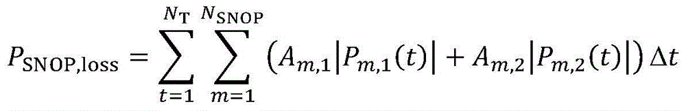
式中,WL、WV分别为配电系统总损耗和系统电压越限的权重系数;系统电压越限情况fV、网络损耗PL,loss与智能软开关的运行损耗PSNOP,loss分别用下式表示In the formula, W L and W V are the weight coefficients of the total loss of the power distribution system and the system voltage over-limit respectively; the system voltage over-limit condition f V , the network loss P L,loss and the operation loss P SNOP,loss of the intelligent soft switch are respectively represented by the following formula


式中,NT为优化计算的时段数,NN为系统中的节点总数,NSNOP为系统中接入智能软开关的个数,Δt为优化计算的时段间隔,Uthr,max和Uthr,min分别为节点电压幅值的优化区间上下限;Ωb为系统支路的集合,Ui(t)为t时段节点i的电压幅值,rij为支路ij的电阻,Iij(t)为t时段节点i流向节点j的电流幅值;Pm,1(t)和Pm,2(t)为t时段第m个智能软开关的两个换流器的有功输出功率,Am,1和Am,2为第m个智能软开关的两个换流器的有功损耗系数。In the formula, N T is the number of time periods for optimization calculation, N N is the total number of nodes in the system, N SNOP is the number of connected smart soft switches in the system, Δt is the time interval of optimization calculation, U thr, max and U thr , min are the upper and lower limits of the optimal interval of node voltage amplitude, respectively; Ω b is the set of system branches, U i (t) is the voltage amplitude of node i during t period, r ij is the resistance of branch ij, I ij ( t) is the amplitude of the current flowing from node i to node j in the t period; P m,1 (t) and P m,2 (t) are the active output powers of the two inverters of the mth smart soft switch in the t period, A m,1 and A m,2 are the active power loss coefficients of the two converters of the mth smart soft switch.
步骤2)所述的系统交流潮流约束表示为:The system AC power flow constraint described in step 2) is expressed as:


Pi(t)=PDG,i(t)+PSNOP,i(t)-Pc,i(t)+Pdic,i(t)-PL,i(t)P i (t)=P DG,i (t)+P SNOP,i (t)-P c,i (t)+P dic,i (t)-P L,i (t)
Qi(t)=QDG,i(t)+QSNOP,i(t)+QESS,i(t)+QSVC,i(t)+QSCB,i(t)-QL,i(t)Q i (t)=Q DG,i (t)+Q SNOP,i (t)+Q ESS,i (t)+Q SVC,i (t)+Q SCB,i (t)-Q L,i (t)
式中,ΩOLTC为含有载调压变压器支路的集合;xij为支路ij的电抗;Pij(t)为t时段支路上节点i流向节点j的有功功率,Qij(t)为t时段支路上节点i流向节点j的无功功率;POLTC,ij(t)为t时段含有载调压变压器支路上节点i流向节点j的有功功率,QOLTC,ij(t)为t时段含有载调压变压器支路上节点i流向节点j的无功功率;Pi(t)为t时段节点i上注入的有功功率之和,PDG,i(t)、PSNOP,i(t)、Pc,i(t)、Pdic,i(t)、PL,i(t)分别为t时段节点i上分布式电源注入的有功功率、智能软开关装置传输的有功功率、储能装置吸收的有功功率、储能装置注入的有功功率、负荷消耗的有功功率,Qi(t)为t时段节点i上注入的有功功率之和,QDG,i(t)、QSNOP,i(t)、QESS,i(t)、QSVC,i(t)、QSCB,i(t)、QL,i(t)分别为t时段节点i上分布式电源注入的无功功率、智能软开关装置发出的无功功率、储能装置注入的无功功率、静止无功补偿器注入的无功功率、可投切电容器组注入的无功功率、负荷消耗的无功功率。In the formula, Ω OLTC is the set containing the branches of the on-load voltage regulating transformer; x ij is the reactance of the branch ij; P ij (t) is the active power flowing from node i to node j on the branch during t period, and Q ij (t) is Reactive power flowing from node i to node j on the branch in period t; P OLTC,ij (t) is the active power flowing from node i to node j on the branch of the on-load voltage regulating transformer in period t, and Q OLTC,ij (t) is period t Contains the reactive power flowing from node i to node j on the branch of the on-load voltage regulating transformer; P i (t) is the sum of the active power injected at node i during t period, P DG,i (t), P SNOP,i (t) , P c,i (t), P dic,i (t), and P L,i (t) are the active power injected by the distributed power generation, the active power transmitted by the intelligent soft-switching device, and the energy storage at the node i during the t period, respectively. The active power absorbed by the device, the active power injected by the energy storage device, and the active power consumed by the load, Q i (t) is the sum of the active power injected at node i in the t period, Q DG,i (t), Q SNOP,i (t), Q ESS,i (t), Q SVC,i (t), Q SCB,i (t), Q L,i (t) are the reactive power injected by the distributed power generation on node i in the t period, respectively , Reactive power emitted by intelligent soft switching device, reactive power injected by energy storage device, reactive power injected by static var compensator, reactive power injected by switchable capacitor bank, reactive power consumed by load.
步骤2)所述的智能软开关运行约束可表示为:The operation constraints of the intelligent soft switch described in step 2) can be expressed as:
Pm,1(t)+Pm,2(t)+Am,1|Pm,1(t)|+Am,2|Pm,2(t)|=0P m,1 (t)+P m,2 (t)+A m,1 |P m,1 (t)|+A m,2 |P m,2 (t)|=0


-Qm,1,max≤Qm,1(t)≤Qm,1,max -Q m,1,max ≤Q m,1 (t)≤Q m,1,max
-Qm,2,max≤Qm,2(t)≤Qm,2,max -Q m,2,max ≤Q m,2 (t)≤Q m,2,max
式中,Qm,1(t)和Qm,2(t)为t时段第m个智能软开关的两个换流器输出的无功功率;Sm,1,max、Sm,2,max、Qm,1,max、Qm,2,max分别为第m个智能软开关的两个换流器的接入容量和所能输出的无功功率上限。In the formula, Q m,1 (t) and Q m,2 (t) are the reactive powers output by the two converters of the mth smart soft switch in the t period; S m,1,max , S m,2 ,max , Q m,1,max , Q m,2,max are respectively the access capacity of the two converters of the mth smart soft switch and the upper limit of reactive power that can be output.
步骤2)所述的有载调压变压器运行约束表示为:The operation constraints of the on-load voltage regulating transformer described in step 2) are expressed as:
Ui(t)=kij(t)Uj(t)U i (t)=k ij (t)U j (t)
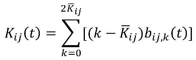
kij(t)=kij,0+Kij(t)Δkij k ij (t)=k ij,0 +K ij (t)Δk ij

式中,kij(t)为t时段支路ij上有载调压变压器的变比,Kij(t)、
步骤3)所述的考虑多种调节手段的配电网综合电压无功控制问题的时序优化模型中非线性目标函数和非线性约束条件进行线性化和锥转换,转化为混合整数二阶锥模型,具体转化方法包括:Step 3) The nonlinear objective function and nonlinear constraints in the time series optimization model for the comprehensive voltage and reactive power control problem of the distribution network considering multiple adjustment means are linearized and cone transformed, and converted into mixed integer second-order cones Model, the specific transformation methods include:
(1)目标函数中智能软开关运行损耗和智能软开关运行约束条件中含有绝对值项|Pm,1(t)|和|Pm,2(t)|,引入辅助变量M1(t)=|Pm,1(t)|=max{Pm,1(t),-Pm,1(t)}和M2(t)=|Pm,2(t)|=max{Pm,2(t),-Pm,2(t)},并增加约束进行线性化:(1) There are absolute value terms |P m,1 (t)| and |P m,2 (t)| in the intelligent soft-switching operation loss and intelligent soft-switching operation constraints in the objective function, and the auxiliary variable M 1 (t) is introduced. )=|P m,1 (t)|=max{P m,1 (t),-P m,1 (t)} and M 2 (t)=|P m,2 (t)|=max{ P m,2 (t),-P m,2 (t)}, and add constraints to linearize:
M1(t)≥0,M2(t)≥0M 1 (t)≥0, M 2 (t)≥0
M1(t)≥Pm,1(t),M1(t)≥-Pm,1(t)M 1 (t)≥P m,1 (t),M 1 (t)≥-P m,1 (t)
M2(t)≥Pm,2(t),M2(t)≥-Pm,2(t);M 2 (t)≥P m,2 (t), M 2 (t)≥-P m,2 (t);
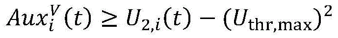
(2)目标函数中系统电压越限情况fV是阈值函数,即当节点电压Ui(t)不在节点电压幅值的优化区间[Uthr,min,Uthr,max]内时,目标函数中fV产生作用,引入表示电压越限情况的辅助变量

(3)目标函数中系统网络损耗与系统交流潮流约束条件中的含有二次项


系统交流潮流约束经替换二次项后,松弛为二阶锥约束After replacing the quadratic term, the system AC power flow constraint is relaxed to a second-order cone constraint
||[2Pij(t) 2Qij(t) I2,ij(t)-U2,i(t)]T||2≤I2,ij(t)-U2,i(t);||[2P ij (t) 2Q ij (t) I 2,ij (t)-U 2,i (t)] T || 2 ≤I 2,ij (t)-U 2,i (t);
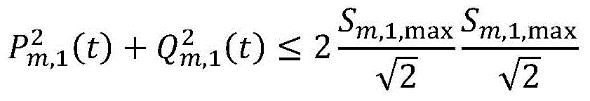
(4)智能软开关容量约束为非线性约束,转换为旋转锥约束(4) The intelligent soft switching capacity constraint is a nonlinear constraint, which is converted into a rotating cone constraint
(5)有载调压变压器运行约束采用U2i(t)和I2ij(t)替换二次项


kij(t)=kij,0+Kij(t)Δkij k ij (t)=k ij,0 +K ij (t)Δk ij
整数变量Kij(t)可用一组二进制变量bij,k(t)表示为The integer variable K ij (t) can be represented by a set of binary variables b ij,k (t) as
代入有载调压变压器运行约束后可得After substituting the operation constraints of the on-load voltage regulating transformer, we can get

连续变量和二进制整数变量的非线性乘积U2,j(t)bij,k(t)可采用辅助变量


0≤bij,k(t)≤1 bij,k(t)∈Ζ0≤b ij,k (t)≤1 b ij,k (t)∈Z
式中,Uj,min和Uj,max分别为节点j的最小允许电压值和最大允许电压值。In the formula, U j,min and U j,max are the minimum allowable voltage value and the maximum allowable voltage value of node j, respectively.
本发明的基于混合整数锥规划的智能配电网综合电压无功优化方法,本发明依据锥优化算法的基本原理,对优化模型的目标函数与约束条件进行了线性化和锥转化,将原问题转化为混合整数二阶锥规划问题(MISOCP),大大降低了求解难度,便于使用求解工具进行求解。本发明所采用的混合整数锥规划可以对考虑多种调节手段的配电网综合电压无功控制问题进行统一描述,使得复杂的混合整数非线性规划的问题求解得以实现,避免了繁琐的迭代和大量的测试,在计算速度上有较大地提升。并且,因为锥所具有的优美的几何结构和特殊的处理方式,使其能够保证所求解问题的解的最优性,将其应用到配电网综合电压无功控制问题中,可以快速获得最优的系统运行方案。The present invention provides a comprehensive voltage and reactive power optimization method for an intelligent distribution network based on mixed integer cone programming. According to the basic principle of the cone optimization algorithm, the present invention performs linearization and cone transformation on the objective function and constraint conditions of the optimization model, and transforms the original problem into It is converted into a mixed integer second-order cone programming problem (MISOCP), which greatly reduces the difficulty of solving and facilitates the use of solving tools. The mixed integer cone programming adopted in the present invention can uniformly describe the comprehensive voltage and reactive power control problem of the distribution network considering various adjustment means, so that the problem solving of the complex mixed integer nonlinear programming can be realized, and the tedious iteration and processing can be avoided. A large number of tests have greatly improved the calculation speed. Moreover, because of the beautiful geometric structure and special processing method of the cone, it can ensure the optimality of the solution to the problem to be solved, and it can be applied to the comprehensive voltage and reactive power control problem of the distribution network, which can quickly obtain the optimal solution. optimal system operation.
附图说明Description of drawings
图1是修改后的IEEE33节点算例和分布式电源、储能、SNOP、SVC、电容器组接入位置图;Figure 1 is the modified IEEE33 node calculation example and the access location diagram of distributed power supply, energy storage, SNOP, SVC, and capacitor bank;
图2是本发明基于混合整数锥规划的智能配电网综合电压无功优化方法的流程图;Fig. 2 is the flow chart of the integrated voltage and reactive power optimization method of intelligent distribution network based on mixed integer cone programming of the present invention;
图3是分布式电源及负荷运行特性的日预测曲线;Figure 3 is the daily forecast curve of the distributed power and load operating characteristics;
图4a是智能软开关(SNOP)装置传输的有功功率变化情况;Fig. 4a shows the variation of active power transmitted by a smart soft switch (SNOP) device;
图4b是智能软开关(SNOP)装置两端发出的无功功率变化情况;Figure 4b shows the variation of reactive power emitted by both ends of the Smart Soft Switch (SNOP) device;
图5a是储能装置的充放电曲线;Fig. 5a is the charge-discharge curve of the energy storage device;
图5b是储能装置的无功功率变化情况;Figure 5b shows the variation of reactive power of the energy storage device;
图6是静止无功补偿器的无功优化策略;Fig. 6 is the reactive power optimization strategy of static var compensator;
图7是电容器组动态优化投切策略;Figure 7 is the dynamic optimization switching strategy of capacitor bank;
图8是有载调压变压器分接头的变化情况;Figure 8 is the change of the tap of the on-load voltage regulating transformer;
图9是进行电压无功优化前后节点18电压的变化情况;Fig. 9 is the change of the voltage of the
图10a是进行电压无功优化前系统电压极值的变化情况;Figure 10a shows the change of the extreme value of the system voltage before the optimization of voltage and reactive power;
图10b是进行电压无功优化后系统电压极值的变化情况。Figure 10b shows the change of the extreme value of the system voltage after the voltage and reactive power optimization is performed.
具体实施方式Detailed ways
下面结合实施过程和附图对本发明的基于混合整数锥规划的智能配电网综合电压无功优化方法做出详细说明。The method for optimizing the comprehensive voltage and reactive power of an intelligent distribution network based on mixed integer cone programming of the present invention will be described in detail below with reference to the implementation process and the accompanying drawings.
本发明的基于混合整数锥规划的智能配电网综合电压无功优化方法,用于配电系统电压无功控制问题研究,可以采用集成于MATLAB上的MOSEK、CPLEX、GUROBI等求解器进行求解。本发明采用CPLEX求解器求解上述混合整数二阶锥规划问题,以图1所示的含多种电压无功调节手段的IEEE 33节点测试系统为实施例。The integrated voltage and reactive power optimization method of the intelligent distribution network based on mixed integer cone programming of the present invention is used for the research of the voltage and reactive power control problems of the power distribution system, and can be solved by using solvers such as MOSEK, CPLEX, GUROBI integrated on MATLAB. In the present invention, the CPLEX solver is used to solve the above mixed integer second-order cone programming problem, and the
本发明的基于混合整数锥规划的智能配电网综合电压无功优化方法,如图2所示,包括如下步骤:The comprehensive voltage and reactive power optimization method for intelligent distribution network based on mixed integer cone programming of the present invention, as shown in FIG. 2 , includes the following steps:
1)输入配电系统的线路参数、负荷水平、网络拓扑连接关系,可调度的分布式电源和储能装置的接入位置、类型、容量及参数,智能软开关装置(SNOP)的接入位置、容量及参数,有载调压变压器(OLTC)的接入位置、容量及参数,可投切电容器组(SCB)的接入位置、容量及参数,静止无功补偿器(SVC)的接入位置、容量及参数,电压无功优化优化周期内负荷及分布式电源运行特性预测曲线,系统运行电压水平和支路电流限制,系统基准电压和基准功率;1) Enter the line parameters, load level, network topology connection relationship of the power distribution system, the access position, type, capacity and parameters of the dispatchable distributed power supply and energy storage device, and the access position of the intelligent soft switch device (SNOP) , capacity and parameters, access position, capacity and parameters of on-load voltage regulating transformer (OLTC), access position, capacity and parameters of switchable capacitor bank (SCB), access to static var compensator (SVC) Location, capacity and parameters, voltage and reactive power optimization optimization cycle load and distributed power operating characteristics prediction curve, system operating voltage level and branch current limit, system reference voltage and reference power;
对于本实施例,首先输入IEEE 33节点系统中线路元件的阻抗值,负荷元件的有功功率、无功功率,详细参数见表1和表2;然后设定5台风电机组的接入位置为节点10、16、17、30、31,接入容量分别为500kVA、300kVA、200kVA、200kVA、300kVA,3台光伏系统的接入位置为节点7、13、27,接入容量分别为500kVA、300kVA、400kVA,功率因数均为0.9;储能装置的接入位置为节点28,总充放电功率上限为500kW,储能逆变器的无功出力上限为100kVar,总电量上限为1000kWh,充放电效率均为95%;每个优化周期内储能装置运行状态改变的允许最大次数为8次;静止无功补偿器的接入位置为节点25,无功最大补偿容量为100kVar;可投切电容器组的接入位置为节点18,最大接入组数为5组,每组容量为50kVar,每个优化周期内电容器组数的允许改变次数为10次;有载调压变压器的接入位置为节点6和节点26之间,可调的档位范围为±5档,调节步长为0.01,电压可调范围为[0.95-1.05];一组SNOP的接入位置为节点12和节点22之间,SNOP两端换流器的容量均为300kVA,无功功率输出上限均为200kVar,两个换流器的有功损耗系数均为0.05;以1小时为时间间隔,利用负荷预测方法来模拟负荷以及风电、光伏的日运行曲线,如图3所示;系统总损耗和系统电压越限情况的加权系数分别为0.836和0.167,可由层次分析法计算得到;各节点电压幅值(标幺值)的安全运行上下限分别为1.05和0.95,各节点电压幅值的优化区间上下限分别为1.02和0.98;最后设置系统的基准电压为12.66kV、基准功率为1MVA。For this embodiment, first enter the impedance value of the line element in the IEEE 33 node system, the active power and reactive power of the load element, see Table 1 and Table 2 for detailed parameters; then set the access position of the five wind turbines as the node 10, 16, 17, 30, and 31, the access capacities are 500kVA, 300kVA, 200kVA, 200kVA, 300kVA, and the access positions of the three PV systems are nodes 7, 13, and 27, and the access capacities are 500kVA, 300kVA, 400kVA, the power factor is 0.9; the access position of the energy storage device is node 28, the upper limit of the total charge and discharge power is 500kW, the upper limit of the reactive power output of the energy storage inverter is 100kVar, the upper limit of the total power is 1000kWh, and the charge and discharge efficiency is both is 95%; the maximum allowable number of changes in the operating state of the energy storage device in each optimization cycle is 8; the access position of the static var compensator is node 25, and the maximum reactive power compensation capacity is 100kVar; the switchable capacitor bank The access position is node 18, the maximum number of access groups is 5 groups, the capacity of each group is 50kVar, and the allowable number of changes in the number of capacitor groups in each optimization period is 10 times; the access position of the on-load voltage regulating transformer is node 6 and node 26, the adjustable gear range is ±5 gears, the adjustment step is 0.01, and the voltage adjustable range is [0.95-1.05]; the access position of a group of SNOPs is between node 12 and node 22, The capacity of the converters at both ends of the SNOP is 300kVA, the upper limit of reactive power output is 200kVar, and the active power loss coefficients of the two converters are both 0.05; the load prediction method is used to simulate the load and wind power at an interval of 1 hour. , the daily operation curve of photovoltaics, as shown in Figure 3; the weighting coefficients of the total system loss and the system voltage over-limit condition are 0.836 and 0.167 respectively, which can be calculated by the AHP; the safety of the voltage amplitude (per unit value) of each node The upper and lower limits of operation are 1.05 and 0.95, respectively, and the upper and lower limits of the optimal interval of the voltage amplitude of each node are 1.02 and 0.98, respectively. Finally, the reference voltage of the system is set to 12.66kV and the reference power is 1MVA.
2)依据步骤1)提供的配电系统结构及参数,同时考虑系统电压越限情况和系统网络损耗及智能软开关(SNOP)的运行损耗,建立考虑多种调节手段的配电网综合电压无功控制问题的时序优化模型,包括:选取根节点为平衡节点,设定配电系统总损耗和电压越限的加权之和最小为目标函数,分别考虑系统交流潮流约束、系统安全运行约束、智能软开关(SNOP)运行约束、分布式电源和储能装置运行约束、有载调压变压器运行约束、静止无功补偿器运行约束和可投切电容器组运行约束;其中,2) According to the structure and parameters of the distribution system provided in step 1), and at the same time considering the over-limit condition of the system voltage, the loss of the system network and the operation loss of the intelligent soft switch (SNOP), establish a comprehensive voltage distribution network that considers multiple adjustment methods. The time series optimization model of power control problem, including: selecting the root node as the balance node, setting the weighted sum of the total loss and voltage overrun of the power distribution system as the minimum objective function, considering the system AC power flow constraints, system safe operation constraints, intelligent Soft switching (SNOP) operation constraints, distributed power supply and energy storage device operation constraints, on-load voltage regulator transformer operation constraints, static var compensator operation constraints and switchable capacitor bank operation constraints; among them,
(1)所述的配电系统总损耗和电压越限的加权之和最小为目标函数可表示为(1) The weighted sum of the total loss of the power distribution system and the voltage exceeding the limit is the minimum objective function, which can be expressed as
min f=WL(PL,loss+PSNOP,loss)+WVfV (1)min f=W L (P L,loss +P SNOP,loss )+W V f V (1)
式中,WL、WV分别为配电系统网络损耗和系统电压越限的权重系数;系统电压越限情况fV、网络损耗PL,loss与智能软开关(SNOP)的运行损耗PSNOP,loss分别可用下式表示In the formula, W L and W V are the weight coefficients of power distribution system network loss and system voltage out-of-limit, respectively; system voltage out-of-limit condition f V , network loss P L,loss and intelligent soft switch (SNOP) operating loss P SNOP , loss can be expressed by the following formulas respectively


式中,NT为优化计算的时段数,NN为系统中的节点总数,NSNOP为系统中接入智能软开关(SNOP)的个数,Δt为优化计算的时段间隔,Uthr,max和Uthr,min分别为节点电压幅值的优化区间上下限;Ωb为系统支路的集合,Ui(t)为t时段节点i的电压幅值,rij为支路ij的电阻,Iij(t)为t时段节点i流向节点j的电流幅值;Pm,1(t)和Pm,2(t)为t时段第m个智能软开关(SNOP)的两个换流器的有功输出功率,Am,1和Am,2为第m个智能软开关(SNOP)的两个换流器的有功损耗系数。In the formula, N T is the number of time periods for optimization calculation, N N is the total number of nodes in the system, N SNOP is the number of smart soft switches (SNOPs) connected to the system, Δt is the time interval of optimization calculation, U thr,max and U thr,min are the upper and lower limits of the optimal interval of node voltage amplitude, respectively; Ω b is the set of system branches, U i (t) is the voltage amplitude of node i during t period, r ij is the resistance of branch ij, I ij (t) is the amplitude of the current flowing from node i to node j in the t period; P m,1 (t) and P m,2 (t) are the two commutations of the mth smart soft switch (SNOP) in the t period is the active output power of the converter, and Am ,1 and Am ,2 are the active loss coefficients of the two converters of the mth Smart Soft Switch (SNOP).
(2)所述的系统交流潮流约束可表示为(2) The system AC power flow constraint can be expressed as


Pi(t)=PDG,i(t)+PSNOP,i(t)-Pc,i(t)+Pdic,i(t)-PL,i(t) (9)P i (t)=P DG,i (t)+P SNOP,i (t)-P c,i (t)+P dic,i (t)-P L,i (t) (9)
Qi(t)=QDG,i(t)+QSNOP,i(t)+QESS,i(t)+QSVC,i(t)+QSCB,i(t)-QL,i(t) (10)Q i (t)=Q DG,i (t)+Q SNOP,i (t)+Q ESS,i (t)+Q SVC,i (t)+Q SCB,i (t)-Q L,i (t) (10)
式中,ΩOLTC为含有载调压变压器支路的集合;xij为支路ij的电抗;Pij(t)为t时段支路上节点i流向节点j的有功功率,Qij(t)为t时段支路上节点i流向节点j的无功功率;POLTC,ij(t)为t时段含有载调压变压器支路上节点i流向节点j的有功功率,QOLTC,ij(t)为t时段含有载调压变压器支路上节点i流向节点j的无功功率;Pi(t)为t时段节点i上注入的有功功率之和,PDG,i(t)、PSNOP,i(t)、Pc,i(t)、Pdic,i(t)、PL,i(t)分别为t时段节点i上分布式电源注入的有功功率、智能软开关(SNOP)传输的有功功率、储能装置吸收的有功功率、储能装置注入的有功功率、负荷消耗的有功功率,Qi(t)为t时段节点i上注入的有功功率之和,QDG,i(t)、QSNOP,i(t)、QESS,i(t)、QSVC,i(t)、QSCB,i(t)、QL,i(t)分别为t时段节点i上分布式电源注入的无功功率、智能软开关(SNOP)发出的无功功率、储能装置注入的无功功率、静止无功补偿器注入的无功功率、可投切电容器组注入的无功功率、负荷消耗的无功功率。In the formula, Ω OLTC is the set containing the branches of the on-load voltage regulating transformer; x ij is the reactance of the branch ij; P ij (t) is the active power flowing from node i to node j on the branch during t period, and Q ij (t) is Reactive power flowing from node i to node j on the branch in period t; P OLTC,ij (t) is the active power flowing from node i to node j on the branch of the on-load voltage regulating transformer in period t, and Q OLTC,ij (t) is period t Contains the reactive power flowing from node i to node j on the branch of the on-load voltage regulating transformer; P i (t) is the sum of the active power injected at node i during t period, P DG,i (t), P SNOP,i (t) , P c,i (t), P dic,i (t), and P L,i (t) are the active power injected by the distributed power generation on node i in the t period, the active power transmitted by the smart soft switch (SNOP), The active power absorbed by the energy storage device, the active power injected by the energy storage device, and the active power consumed by the load, Q i (t) is the sum of the active power injected at the node i during the t period, Q DG,i (t), Q SNOP , i (t), Q ESS,i (t), Q SVC,i (t), Q SCB,i (t), and Q L,i (t) are the non-volatile power injected by the distributed power generation on node i in the t period, respectively. Active power, reactive power emitted by intelligent soft switching (SNOP), reactive power injected by energy storage device, reactive power injected by static var compensator, reactive power injected by switchable capacitor bank, reactive power consumed by load work power.
(3)所述的系统安全运行约束可表示为(3) The system safe operation constraint can be expressed as


式中,Ui,min和Ui,max分别为节点i的最小允许电压值和最大允许电压值;Iij,max为支路ij的最大允许电流值。In the formula, U i,min and U i,max are the minimum allowable voltage value and maximum allowable voltage value of node i respectively; I ij,max is the maximum allowable current value of branch ij.
(4)所述的智能软开关(SNOP)运行约束可表示为(4) The smart soft switch (SNOP) operating constraints can be expressed as
Pm,1(t)+Pm,2(t)+Am,1|Pm,1(t)|+Am,2|Pm,2(t)|=0 (13)P m,1 (t)+P m,2 (t)+A m,1 |P m,1 (t)|+A m,2 |P m,2 (t)|=0 (13)

-Qm,1,max≤Qm,1(t)≤Qm,1,max (16)-Q m,1,max ≤Q m,1 (t)≤Q m,1,max (16)
-Qm,2,max≤Qm,2(t)≤Qm,2,max (17)-Q m,2,max ≤Q m,2 (t)≤Q m,2,max (17)
式中,Qm,1(t)和Qm,2(t)为t时段第m个智能软开关(SNOP)两个换流器输出的无功功率;Sm,1,max、Sm,2,max、Qm,1,max、Qm,2,max分别为第m个智能软开关(SNOP)两个换流器的接入容量和所能输出的无功功率上限。In the formula, Q m,1 (t) and Q m,2 (t) are the reactive powers output by the m-th smart soft-switching (SNOP) two converters in the t period; S m,1,max , S m ,2,max , Q m,1,max , Q m,2,max are the access capacity and the upper limit of reactive power output of the mth smart soft switch (SNOP) two converters, respectively.
(5)所述的分布式电源运行约束可表示为(5) The distributed power operating constraints can be expressed as
PDG,i(t)≥0 (19)P DG,i (t)≥0 (19)
-QDG,i,max≤QDG,i(t)≤QDG,i,max (20)-Q DG,i,max ≤Q DG,i (t)≤Q DG,i,max (20)
式中,SDG,i、QDG,i,max分别为节点i上分布式电源的接入容量和所能输出的无功功率上限。In the formula, SD DG,i and Q DG,i,max are the access capacity of the distributed power source on the node i and the upper limit of the reactive power that can be output, respectively.
所述的储能装置运行约束可表示为The energy storage device operating constraints can be expressed as
Pc,i,mineESS,i(t)≤Pc,i(t)≤Pc,i,maxeESS,i(t) (21)P c,i,min e ESS,i (t)≤P c,i (t)≤P c,i,max e ESS,i (t) (21)
Pdic,i,min(1-eESS,i(t))≤Pdic,i(t)≤Pdic,i,max(1-eESS,i(t)) (22)P dic,i,min (1-e ESS,i (t))≤P dic,i (t)≤P dic,i,max (1-e ESS,i (t)) (22)
QESS,i,min≤QESS,i(t)≤QESS,i,max (23)Q ESS,i,min ≤Q ESS,i (t)≤Q ESS,i,max (23)

EESS,i(NT)=EESS,i(1) (25)E ESS,i (N T )=E ESS,i (1) (25)
EESS,i,min≤EESS,i(t)≤EESS,i,max (26)E ESS,i,min ≤E ESS,i (t)≤E ESS,i,max (26)

0≤eESS,i(t)≤1 eESS,i(t)∈Ζ (28)0≤e ESS,i (t)≤1 e ESS,i (t)∈Z (28)
式中,EESS,i(t)为t时段节点i上储能装置的电量,eESS,i(t)表示t时段节点i上储能装置的运行状态;Pc,i,min、Pc,i,max分别为节点i上储能装置的充电功率下限和上限,Pdic,i,min、Pdic,i,max分别为节点i上储能装置的放电功率下限和上限,QESS,i,min、QESS,i,max分别为节点i上储能装置所能输出的无功功率下限和上限,EESS,i,min、EESS,i,max分别为节点i上储能装置的存储电量下限和上限,ΔESS,max为优化计算周期内储能装置运行状态改变的最大允许次数。In the formula, E ESS,i (t) is the power of the energy storage device on the node i in the t period, e ESS,i (t) represents the operation state of the energy storage device on the node i in the t period; P c,i,min , P c,i,max are the lower limit and upper limit of the charging power of the energy storage device on node i, respectively, P dic,i,min and P dic,i,max are the lower limit and upper limit of the discharge power of the energy storage device on node i, respectively, Q ESS ,i,min , Q ESS,i,max are the lower limit and upper limit of the reactive power output by the energy storage device on node i, respectively, E ESS,i,min , E ESS,i,max are the energy storage on node i, respectively The lower limit and upper limit of the storage power of the device, Δ ESS,max is the maximum allowable number of changes in the operating state of the energy storage device in the optimization calculation period.
(6)所述的有载调压变压器运行约束可表示为(6) The operating constraints of the on-load voltage regulating transformer can be expressed as
Ui(t)=kij(t)Uj(t) (29)U i (t)=k ij (t) U j (t) (29)
kij(t)=kij,0+Kij(t)Δkij (30)k ij (t)=k ij,0 +K ij (t)Δk ij (30)

式中,kij(t)为t时段支路ij上有载调压变压器的变比,Kij(t)、
(7)所述的静止无功补偿装置运行约束可表示为(7) The operating constraints of the static reactive power compensation device can be expressed as
QSVC,min≤QSVC,i(t)≤QSVC,max (32)Q SVC,min ≤Q SVC,i (t)≤Q SVC,max (32)
式中,QSVC,min、QSVC,max分别为节点i上静止无功补偿装置所能输出的无功功率上下限。In the formula, Q SVC,min and Q SVC,max are the upper and lower limits of reactive power output by the static reactive power compensation device on node i, respectively.
(8)所述的可投切电容器组运行约束可表示为(8) The operating constraints of the switchable capacitor bank can be expressed as
QSCB,i(t)=NSCB,i(t)*qSCB,i (33)Q SCB,i (t)=N SCB,i (t)*q SCB,i (33)

0≤NSCB,i(t)≤NSCB,max NSCB,i(t)∈Ζ (35)0≤N SCB,i (t)≤N SCB,max N SCB,i (t)∈Z(35)
式中,NSCB,i(t)为t时段节点i上电容器组的投切组数,qSCB,i为节点i上每一组电容器的无功补偿功率;NSCB,max为节点i上电容器组的最大投切组数,ΔSCB,max为优化计算周期内电容器组数改变的最大允许次数。In the formula, N SCB,i ( t) is the number of switching groups of capacitor banks on node i during t period, q SCB,i is the reactive power compensation of each group of capacitors on node i; The maximum number of switching groups of capacitor banks, Δ SCB,max is the maximum allowable number of changes in the number of capacitor banks in the optimization calculation cycle.
3)根据混合整数锥规划的标准形式对步骤2)所建立的考虑多种调节手段的配电网综合电压无功控制问题的时序优化模型中非线性目标函数和非线性约束条件进行线性化和锥转换,转化为混合整数二阶锥模型;3) According to the standard form of mixed integer cone programming, linearize the nonlinear objective function and nonlinear constraints in the sequential optimization model of the comprehensive voltage and reactive power control problem of distribution network considering multiple adjustment methods established in step 2) and sum up Cone transformation, converted to mixed integer second-order cone model;
(1)目标函数中智能软开关(SNOP)运行损耗(4)和智能软开关(SNOP)运行约束条件(13)中含有绝对值项|Pm,1(t)|和|Pm,2(t)|,引入辅助变量M1(t)=|Pm,1(t)|=max{Pm,1(t),-Pm,1(t)}和M2(t)=|Pm,2(t)|=max{Pm,2(t),-Pm,2(t)},并增加约束进行线性化(1) The smart soft switching (SNOP) operating loss in the objective function (4) and the smart soft switching (SNOP) operating constraints (13) contain absolute value terms |P m,1 (t)| and |P m,2 (t)|, introducing auxiliary variables M 1 (t)=|P m,1 (t)|=max{P m,1 (t),-P m,1 (t)} and M 2 (t)= |P m,2 (t)|=max{P m,2 (t),-P m,2 (t)}, and add constraints to linearize
M1(t)≥0,M2(t)≥0 (36)M 1 (t)≥0, M 2 (t)≥0 (36)
M1(t)≥Pm,1(t),M1(t)≥-Pm,1(t) (37)M 1 (t)≥P m,1 (t),M 1 (t)≥-P m,1 (t) (37)
M2(t)≥Pm,2(t),M2(t)≥-Pm,2(t) (38)M 2 (t)≥P m,2 (t),M 2 (t)≥-P m,2 (t) (38)
(2)目标函数中系统电压越限情况fV是阈值函数,即当节点电压Ui(t)不在节点电压幅值的优化区间[Uthr,min,Uthr,max]内时,目标函数中fV产生作用。引入表示电压越限情况的辅助变量


(3)目标函数中系统网络损耗(3)与系统交流潮流约束条件(5)-(8)中的含有二次项

系统交流潮流约束(7)经上述步骤替换非线性项后,松弛为二阶锥约束After the system AC power flow constraint (7) is replaced by the nonlinear term in the above steps, it is relaxed to a second-order cone constraint
||[2Pij(t) 2Qij(t) I2,ij(t)-U2,i(t)]T||2≤I2,ij(t)-U2,i(t) (42)||[2P ij (t) 2Q ij (t) I 2,ij (t)-U 2,i (t)] T || 2 ≤I 2,ij (t)-U 2,i (t) ( 42)
(4)智能软开关(SNOP)容量约束(14)、(15)和分布式电源容量约束(18)为非线性约束,转换为旋转锥约束(4) Smart Soft Switch (SNOP) capacity constraints (14), (15) and distributed power capacity constraints (18) are nonlinear constraints, which are converted into rotating cone constraints


(5)储能装置运行约束(27)中含有绝对值项,引入表示t时段储能装置运行状态由放电状态切换为充电状态的辅助变量


(6)有载调压变压器运行约束(29)和(30)采用U2,i(t)和I2,ij(t)进行变量后可表示为(6) The operating constraints of the on-load voltage regulating transformer (29) and (30) can be expressed as U 2,i (t) and I 2,ij (t) for variables

kij(t)=kij,0+Kij(t)Δkij (50)k ij (t)=k ij,0 +K ij (t)Δk ij (50)
整数变量Kij(t)可用一组二进制变量bij,k(t)表示为The integer variable K ij (t) can be represented by a set of binary variables b ij,k (t) as

代入有载调压变压器运行约束(49)后可得After substituting the operation constraint (49) of the on-load voltage regulating transformer, we can get

连续变量和二进制整数变量的非线性乘积U2,j(t)bij,k(t)可采用辅助变量


0≤bij,k(t)≤1 bij,k(t)∈Ζ (58)0≤b ij,k (t)≤1 b ij,k (t)∈Z (58)
(7)可投切电容器的运行约束(34)中含有绝对值项,引入表示t时段电容器组投切组数正向变化的辅助变量


4)将得到的混合整数二阶锥模型采用可解混合整数二阶锥规划的数学求解器进行求解;4) The obtained mixed integer second-order cone model is solved by a mathematical solver that can solve mixed-integer second-order cone programming;
5)输出步骤4)的求解结果,包括智能软开关(SNOP)的传输功率值和两端的无功出力值、分布式电源和储能装置的有功无功出力值、有载调压变压器的分接头位置、投切的电容器组数、静止无功补偿器的无功出力值、网络潮流结果以及系统总损耗和系统电压越限情况。5) Output the solution result of step 4), including the transmission power value of the smart soft switch (SNOP) and the reactive power output value at both ends, the active and reactive power output value of the distributed power supply and the energy storage device, and the distribution of the on-load voltage regulating transformer. The position of the joint, the number of capacitor banks switched, the reactive output value of the static var compensator, the result of the network power flow, and the total system loss and system voltage limit.
本发明基于混合整数锥优化算法,建立了考虑多种调节手段的配电网综合电压无功优化模型,以提高分布式电源的并网能力,改善配电网电压水平,消除过电压的情况。Based on the mixed integer cone optimization algorithm, the invention establishes a comprehensive voltage and reactive power optimization model of the distribution network considering multiple adjustment means, so as to improve the grid-connected capability of the distributed power source, improve the voltage level of the distribution network, and eliminate the overvoltage situation.
修改后的IEEE 33节点算例结构如图1所示,本实施例综合考虑各种电压无功优化策略,通过合理调控各无功电源来保证配电网电压水平。以1小时为一个时间断面,静止无功补偿器和电容器组对配电网进行无功补偿,有载调压变压器通过调整分接头改善系统无功分布,分布式电源和储能装置动态调节输出的无功功率,智能软开关(SNOP)装置动态调节两端输出的无功功率,改善馈线电压水平,提高配电网对分布式电源的消纳能力,各调节手段动态优化结果见图4-图8。The modified
执行优化计算的计算机硬件环境为Intel(R)Xeon(R)CPU E5-1620,主频为3.70GHz,内存为32GB;软件环境为Windows 7操作系统。The computer hardware environment for performing optimization calculation is Intel(R) Xeon(R) CPU E5-1620, the main frequency is 3.70GHz, and the memory is 32GB; the software environment is
优化方案综合考虑各种电压无功优化调节手段,对含分布式电源的配电网进行电压无功优化,使配电网各节点的电压在一定程度上得到了改善,提高了供电可靠性,如图9所示;另一方面,可以减小分布式电源接入引起的配电网电压波动问题,有效减小系统电压偏差,保证系统长期安全运行,如图10所示。The optimization scheme comprehensively considers various voltage and reactive power optimization adjustment methods, and optimizes the voltage and reactive power of the distribution network with distributed power sources, so that the voltage of each node of the distribution network has been improved to a certain extent, and the reliability of power supply has been improved. As shown in Figure 9; on the other hand, it can reduce the voltage fluctuation problem of the distribution network caused by the access of distributed power sources, effectively reduce the voltage deviation of the system, and ensure the long-term safe operation of the system, as shown in Figure 10.
智能配电网综合电压无功优化方法在改善配电网电压水平的同时,通过考虑各种调节手段,可以得到较好的降损效果,优化前后系统损耗的比较结果见表3。While improving the voltage level of the distribution network, the comprehensive voltage and reactive power optimization method of the smart distribution network can obtain a better loss reduction effect by considering various adjustment methods. The comparison results of the system loss before and after optimization are shown in Table 3.
配电网综合电压无功控制问题的数学本质是大规模混合整数非线性规划问题,目前已有的优化方法大多无法进行高效求解,本发明提出的一种基于混合整数锥规划的智能配电网综合电压无功优化方法,能够快速、准确的求解此类问题,采用多种调节手段对配电网进行电压无功时序优化。The mathematical essence of the comprehensive voltage and reactive power control problem of the distribution network is a large-scale mixed integer nonlinear programming problem. Most of the existing optimization methods cannot be solved efficiently. The present invention proposes an intelligent distribution network based on mixed integer cone programming. The comprehensive voltage and reactive power optimization method can solve such problems quickly and accurately, and use a variety of adjustment methods to optimize the voltage and reactive power sequence of the distribution network.
表1 IEEE33节点算例负荷接入位置及功率Table 1 Load access location and power of IEEE33 node calculation example

表2 IEEE33节点算例线路参数Table 2 IEEE33 node calculation example line parameters


表3 优化前后系统损耗比较Table 3 Comparison of system losses before and after optimization
Claims (5)


Priority Applications (1)
| Application Number | Priority Date | Filing Date | Title |
|---|---|---|---|
| CN201610049059.9A CN105740973B (en) | 2016-01-25 | 2016-01-25 | Integrated voltage and reactive power optimization method for intelligent distribution network based on mixed integer cone programming |
Applications Claiming Priority (1)
| Application Number | Priority Date | Filing Date | Title |
|---|---|---|---|
| CN201610049059.9A CN105740973B (en) | 2016-01-25 | 2016-01-25 | Integrated voltage and reactive power optimization method for intelligent distribution network based on mixed integer cone programming |
Publications (2)
| Publication Number | Publication Date |
|---|---|
| CN105740973A CN105740973A (en) | 2016-07-06 |
| CN105740973B true CN105740973B (en) | 2020-06-09 |
Family
ID=56247573
Family Applications (1)
| Application Number | Title | Priority Date | Filing Date |
|---|---|---|---|
| CN201610049059.9A Active CN105740973B (en) | 2016-01-25 | 2016-01-25 | Integrated voltage and reactive power optimization method for intelligent distribution network based on mixed integer cone programming |
Country Status (1)
| Country | Link |
|---|---|
| CN (1) | CN105740973B (en) |
Families Citing this family (43)
| Publication number | Priority date | Publication date | Assignee | Title |
|---|---|---|---|---|
| CN106228273B (en) * | 2016-07-29 | 2022-02-22 | 中国电力科学研究院 | Method for constructing hydropower delivery transaction optimization model |
| CN106329523B (en) * | 2016-11-19 | 2018-09-25 | 中国南方电网有限责任公司电网技术研究中心 | Robust optimization modeling method for intelligent soft switching in active distribution network considering uncertainty |
| CN106655177B (en) * | 2017-01-18 | 2018-12-28 | 中国南方电网有限责任公司电网技术研究中心 | Calculation method of maximum access capacity of distributed power generation based on extended second-order cone programming |
| CN106887852B (en) * | 2017-03-06 | 2019-05-14 | 天津大学 | An On-Site Voltage Reactive Power Control Strategy Setting Method for Intermittent Distributed Power Sources |
| CN106786631B (en) * | 2017-03-06 | 2019-07-09 | 天津大学 | Distributed generation resource voltage & var control strategy setting method on the spot based on cone planning |
| CN106921164B (en) * | 2017-04-05 | 2019-10-22 | 广东电网有限责任公司东莞供电局 | Mixed integer second-order cone planning method and system for distribution network voltage reactive power collaborative optimization |
| CN108418223B (en) * | 2017-04-27 | 2020-06-09 | 广东电网有限责任公司佛山供电局 | Active power distribution network reactive voltage coordinated operation optimization method and system |
| CN106972539B (en) * | 2017-05-13 | 2019-05-14 | 天津大学 | A Cone Programming-Based Local Voltage Control Strategy Tuning Method for Distributed Power Sources |
| CN107221930A (en) * | 2017-08-02 | 2017-09-29 | 国家电网公司 | A kind of intelligent Sofe Switch service restoration method of active power distribution network |
| CN107644118B (en) * | 2017-08-04 | 2020-08-14 | 天津大学 | Intelligent power distribution soft switch time sequence optimization method integrating energy storage |
| CN107341623A (en) * | 2017-08-31 | 2017-11-10 | 国家电网公司 | A kind of active power distribution network source storage lotus islet operation method of meter and network reconfiguration |
| CN107591815B (en) * | 2017-09-07 | 2020-09-04 | 华南理工大学 | A Decomposition Method for Solving Reactive Power Optimization of Power System with Discrete Control |
| CN108306342B (en) * | 2018-01-19 | 2021-04-02 | 广东电网有限责任公司佛山供电局 | Distribution network operation control method with DG discrete power factor and equipment action limit |
| CN108199387B (en) * | 2018-01-30 | 2020-02-04 | 广东电网有限责任公司韶关供电局 | Active power distribution network reactive voltage operation control method based on expansion cone planning |
| CN108233383B (en) * | 2018-02-11 | 2019-09-27 | 清华大学 | An Economical Dispatching Method for AC-DC Interconnected Power Grid |
| CN108683179B (en) * | 2018-05-03 | 2020-04-21 | 国网山东省电力公司潍坊供电公司 | Active distribution network optimization scheduling method and system based on mixed integer linear programming |
| CN109390930B (en) * | 2018-06-13 | 2022-05-27 | 南京理工大学 | Active power distribution network microgrid partitioning method considering control autonomy |
| CN110635519B (en) * | 2018-06-22 | 2020-11-20 | 国网江苏省电力有限公司扬州供电分公司 | A method for generating active power dispatch plan for distributed new energy in active distribution network |
| CN108695875B (en) * | 2018-06-28 | 2021-08-20 | 华北电力大学(保定) | Operation optimization method of distribution network with joint access of intelligent soft switch and energy storage device |
| CN108988322B (en) * | 2018-06-30 | 2020-07-07 | 南京理工大学 | Microgrid operation strategy optimization method considering system time-varying property |
| CN108879665B (en) * | 2018-07-03 | 2021-07-27 | 河海大学 | An optimization method for power system safety correction aiming at the minimum number of adjustment devices |
| CN109193809B (en) * | 2018-08-14 | 2021-10-08 | 河海大学 | An optimization method for active power safety correction of power system based on sensitivity matrix |
| CN109638874A (en) * | 2018-10-24 | 2019-04-16 | 中国电力科学研究院有限公司 | A kind of distributed photovoltaic cluster control method and device |
| CN109617092A (en) * | 2018-12-19 | 2019-04-12 | 中国电力科学研究院有限公司 | A method and system for dynamic reactive power optimization of AC-DC hybrid power grid |
| CN109687469B (en) * | 2019-01-11 | 2023-04-28 | 国网天津市电力公司电力科学研究院 | Intelligent soft-switching voltage control method for active distribution network based on chance constrained programming |
| CN109787259B (en) * | 2019-01-23 | 2020-10-27 | 西安交通大学 | A joint planning method of multi-type energy storage based on random fluctuation of new energy |
| CN110059897B (en) * | 2019-05-23 | 2021-03-09 | 合肥工业大学 | Intraday rolling optimization method of active distribution network based on mixed integer PSO algorithm |
| CN110277789B (en) * | 2019-07-16 | 2021-06-29 | 华北电力大学 | Multi-period reactive power optimization method and device for power grid |
| CN110490376B (en) * | 2019-08-05 | 2023-04-07 | 天津大学 | Intelligent soft switch planning method for improving reliability and economy of power distribution network |
| CN110690709B (en) * | 2019-10-22 | 2023-04-28 | 天津大学 | A Sensitivity-Based Intelligent Soft Switch Interval Coordinated Voltage Control Method |
| CN111490552B (en) * | 2020-05-20 | 2023-07-25 | 国网上海市电力公司 | Reactive power optimization method for power distribution network |
| CN111541248B (en) * | 2020-06-11 | 2021-10-15 | 南方电网科学研究院有限责任公司 | A method and device for joint optimization of intelligent soft switch and energy storage system |
| CN112039069B (en) * | 2020-09-04 | 2022-02-22 | 国网山东省电力公司济宁供电公司 | Double-layer collaborative planning method and system for power distribution network energy storage and flexible switch |
| CN112529253B (en) * | 2020-11-18 | 2024-04-12 | 国网青海省电力公司 | Regional power grid dynamic reactive power optimization method based on interior point decoupling method and linear mixed integer programming method |
| CN112865108B (en) * | 2021-01-11 | 2022-09-13 | 国网山西省电力公司忻州供电公司 | Power grid automatic voltage control simulation method based on continuous power flow simulation |
| CN113078678B (en) * | 2021-04-13 | 2022-09-13 | 湖南大学 | DG and SOP active-reactive collaborative planning method and device |
| CN113285456A (en) * | 2021-05-14 | 2021-08-20 | 南京工程学院 | Reactive power optimization method for comprehensive energy system of power distribution network and gas network |
| CN113031451B (en) * | 2021-05-31 | 2021-08-03 | 浙江中控技术股份有限公司 | Steady state optimization method suitable for process industry prediction control |
| CN113541156B (en) * | 2021-06-28 | 2024-01-23 | 国网上海市电力公司 | A reactive voltage adjustment method based on reactor compensation device |
| CN113988384B (en) * | 2021-10-12 | 2025-07-15 | 广西电网有限责任公司电力科学研究院 | A method for optimizing energy storage capacity configuration to improve distribution network reliability |
| CN114092277B (en) * | 2021-11-15 | 2025-10-31 | 浙江华云电力工程设计咨询有限公司 | Flexible regional comprehensive energy system combined cooling, heating and power dispatching method and system |
| CN116632837B (en) * | 2023-07-19 | 2023-12-26 | 国网江西省电力有限公司电力科学研究院 | A voltage regulation method and system for active distribution network |
| CN119010057A (en) * | 2024-07-18 | 2024-11-22 | 长电(张掖)能源发展有限公司 | Pumped storage construction power supply system voltage-reactive compensation control strategy based on hierarchical compensation principle |
Citations (2)
| Publication number | Priority date | Publication date | Assignee | Title |
|---|---|---|---|---|
| CN104376378A (en) * | 2014-11-14 | 2015-02-25 | 浙江工商大学 | Distributed-power-source-contained power distribution network reactive power optimization method based on mixed integer cone optimization |
| CN104794541A (en) * | 2015-04-21 | 2015-07-22 | 天津大学 | Simulated-annealing and conic optimization based power distribution network operation optimization method |
-
2016
- 2016-01-25 CN CN201610049059.9A patent/CN105740973B/en active Active
Patent Citations (2)
| Publication number | Priority date | Publication date | Assignee | Title |
|---|---|---|---|---|
| CN104376378A (en) * | 2014-11-14 | 2015-02-25 | 浙江工商大学 | Distributed-power-source-contained power distribution network reactive power optimization method based on mixed integer cone optimization |
| CN104794541A (en) * | 2015-04-21 | 2015-07-22 | 天津大学 | Simulated-annealing and conic optimization based power distribution network operation optimization method |
Non-Patent Citations (2)
| Title |
|---|
| 基于SNOP的配电网运行优化及分析;王成山等;《电力系统自动化》;20150510;第39卷(第9期);全文 * |
| 基于混合整数二阶锥规划的三相有源配电网无功优化;刘一兵等;《电力系统自动化》;20140810;第38卷(第14期);全文 * |
Also Published As
| Publication number | Publication date |
|---|---|
| CN105740973A (en) | 2016-07-06 |
Similar Documents
| Publication | Publication Date | Title |
|---|---|---|
| CN105740973B (en) | Integrated voltage and reactive power optimization method for intelligent distribution network based on mixed integer cone programming | |
| CN110690732B (en) | Photovoltaic reactive power partition pricing power distribution network reactive power optimization method | |
| Ji et al. | A centralized-based method to determine the local voltage control strategies of distributed generator operation in active distribution networks | |
| Zhang et al. | Coordinated allocation of distributed generation, capacitor banks and soft open points in active distribution networks considering dispatching results | |
| CN109361242B (en) | Automatic voltage control method for photovoltaic power generation | |
| CN108023364B (en) | Power distribution network distributed generation resource maximum access capability calculation method based on convex difference planning | |
| CN106655227B (en) | A feeder load balancing method for active distribution network based on intelligent soft switch | |
| CN106655177B (en) | Calculation method of maximum access capacity of distributed power generation based on extended second-order cone programming | |
| Kamarposhti et al. | Optimal location of FACTS devices in order to simultaneously improving transmission losses and stability margin using artificial bee colony algorithm | |
| CN105119280B (en) | Alternating current-direct current mixed structure active power distribution network running optimizatin method based on cone optimization | |
| CN105719196B (en) | A voltage and reactive power control method of active distribution network based on intelligent soft switch | |
| CN106655226B (en) | Active power distribution network asymmetric operation optimization method based on intelligent Sofe Switch | |
| CN108933448B (en) | Coordination control method and system for medium and low voltage distribution network containing photovoltaic power supply | |
| KR102133897B1 (en) | Method for controlling a voltage and reactive power based on real time measurement, program for the same | |
| CN108683179A (en) | Active distribution network Optimization Scheduling based on mixed integer linear programming and system | |
| CN109842123B (en) | Coordinated dynamic reactive power optimization method for phase-converter and hierarchical UHVDC receiving-side converter station | |
| CN108539797B (en) | An economical method for secondary frequency and voltage control of islanded microgrids | |
| CN111799810A (en) | Method and system for reactive power control of AC/DC system | |
| CN115588991A (en) | An Optimal Power Flow Model Establishment Method for Three-phase Unbalanced Distribution Network | |
| Tshivhase et al. | A fault level-based system to control voltage and enhance power factor through an on-load tap changer and distributed generators | |
| CN107565576A (en) | A kind of active distribution network reactive Voltage Optimum method that more active management means are mutually coordinated | |
| CN106786630A (en) | A kind of voltage power-less optimized controlling method containing polymorphic type distributed power source | |
| CN104319783A (en) | System and method for two-level distribution network coordination control based on load forecasting | |
| CN110247404A (en) | Wind-electricity integration voltage hierarchical coordinative control method, system, medium and equipment | |
| CN114069657A (en) | Double-time-scale voltage coordination control method and system for three-phase unbalanced active power distribution network |
Legal Events
| Date | Code | Title | Description |
|---|---|---|---|
| C06 | Publication | ||
| PB01 | Publication | ||
| C10 | Entry into substantive examination | ||
| SE01 | Entry into force of request for substantive examination | ||
| GR01 | Patent grant | ||
| GR01 | Patent grant | ||
| TR01 | Transfer of patent right | ||
| TR01 | Transfer of patent right |
Effective date of registration: 20210511 Address after: Room 710, block I, Haitai green industrial base, No.6 Haitai development road, Huayuan Industrial Zone, Binhai New Area, Tianjin, 300384 Patentee after: TIANJIN TIANCHENG HENGCHUANG ENERGY TECHNOLOGY Co.,Ltd. Address before: 300072 Tianjin City, Nankai District Wei Jin Road No. 92 Patentee before: Tianjin University |
|
| TR01 | Transfer of patent right | ||
| TR01 | Transfer of patent right |
Effective date of registration: 20220914 Address after: Room 126, Gate 1, Building 3, No. 22, Kaihua Road, Huayuan Industrial Zone, Binhai New Area, Tianjin 300384 Patentee after: Tianjin Baize Qingyuan Technology Co.,Ltd. Address before: Room 710, block I, Haitai green industrial base, No.6 Haitai development road, Huayuan Industrial Zone, Binhai New Area, Tianjin, 300384 Patentee before: TIANJIN TIANCHENG HENGCHUANG ENERGY TECHNOLOGY Co.,Ltd. |