CN105577415B - Intelligent optical distribution network equipment - Google Patents
Intelligent optical distribution network equipment Download PDFInfo
- Publication number
- CN105577415B CN105577415B CN201410555247.XA CN201410555247A CN105577415B CN 105577415 B CN105577415 B CN 105577415B CN 201410555247 A CN201410555247 A CN 201410555247A CN 105577415 B CN105577415 B CN 105577415B
- Authority
- CN
- China
- Prior art keywords
- signal
- module
- interface
- connector
- assembly unit
- Prior art date
- Legal status (The legal status is an assumption and is not a legal conclusion. Google has not performed a legal analysis and makes no representation as to the accuracy of the status listed.)
- Active
Links
Images


Classifications
-
- H—ELECTRICITY
- H04—ELECTRIC COMMUNICATION TECHNIQUE
- H04B—TRANSMISSION
- H04B10/00—Transmission systems employing electromagnetic waves other than radio-waves, e.g. infrared, visible or ultraviolet light, or employing corpuscular radiation, e.g. quantum communication
- H04B10/25—Arrangements specific to fibre transmission
Landscapes
- Physics & Mathematics (AREA)
- Electromagnetism (AREA)
- Engineering & Computer Science (AREA)
- Computer Networks & Wireless Communication (AREA)
- Signal Processing (AREA)
- Communication Control (AREA)
- Small-Scale Networks (AREA)
Abstract
本发明提供了一种智能光分配网络设备,包括:组配单元、控制单元,所述组配单元与所述控制单元通过RS485接口连接。采用本发明提供的上述技术方案,解决了相关技术中,ODN设备内部组成单元不能统一对接以及智能ODN设备内部需要进行较多的协议转换,从而避免了模块之间的协议转换,实现不同厂商ODN设备内部单元的统一对接。
The invention provides an intelligent optical distribution network device, comprising: an assembly unit and a control unit, wherein the assembly unit and the control unit are connected through an RS485 interface. The above technical solution provided by the present invention solves the problem that in the related art, the internal components of the ODN equipment cannot be connected uniformly and the intelligent ODN equipment needs to perform more protocol conversions, thereby avoiding the protocol conversion between modules and realizing the ODN of different manufacturers. Unified docking of internal units of the device.
Description
技术领域technical field
本发明涉及通信领域,具体而言,涉及一种智能(Intelligent)光分配网络(Optical Distribution Network,简称为ODN)设备。The present invention relates to the field of communications, and in particular, to an intelligent (Intelligent) optical distribution network (Optical Distribution Network, ODN for short) device.
背景技术Background technique
智能ODN系统(Intelligent Optical Distribution Network)的基本组成包括智能ODN设备、智能管理终端、智能ODN管理系统等三大部分。The basic composition of the intelligent ODN system (Intelligent Optical Distribution Network) includes three parts: intelligent ODN equipment, intelligent management terminal, and intelligent ODN management system.
移动运营商定义了电子标签载体包括具有电子标签的光跳纤、尾纤等类型的光纤,主要完成承载电子标签的功能,通过I1接口与智能ODN设备连接;智能管理终端和智能ODN设备之间的I2接口必须是RJ45接头的RS485接口,并支持供电。智能管理终端和智能ODN设备之间I2接口的RJ45接头包含电源VCC、地GND、数据正端RS485_P、数据负端RS485_N四个信号。Mobile operators have defined electronic label carriers, including optical fibers with electronic labels, such as optical fiber jumpers, pigtails, etc., which mainly complete the function of carrying electronic labels, and are connected to intelligent ODN devices through the I1 interface; between intelligent management terminals and intelligent ODN devices The I2 interface must be the RS485 interface of the RJ45 connector and support power supply. The RJ45 connector of the I2 interface between the intelligent management terminal and the intelligent ODN device includes four signals: power VCC, ground GND, data positive terminal RS485_P, and data negative terminal RS485_N.
智能ODN设备包括组配单元、控制单元等。组配单元包括智能熔配模块等,完成光配线设备具有的光纤连接、分配和调度等功能。控制单元完成对外通信、端口管理以及数据存储等功能。但是移动运营商没有定义智能ODN设备内部接口,实际中各个设备厂商按照自己的想法设计智能ODN设备内部接口,没有形成统一标准。有的厂商采用CAN总线,也有的厂商采用I2C、RS232等总线,性能、成本、可靠性方面各有优缺点。因为没有统一的标准,不同设备厂商的智能ODN设备内部模块单元不能对接,对智能ODN系统的大规模商用推广不利,并且相关技术中智能管理终端和智能ODN设备之间I2接口为RJ485接口,而智能ODN设备内部单元之间的接口为非RJ485接口,不能实现内部单元的直接对接,需要进行协议转换。The intelligent ODN equipment includes an assembly unit, a control unit, and the like. The assembly unit includes intelligent fusion and distribution modules, etc., to complete the optical fiber connection, distribution and scheduling functions of the optical distribution equipment. The control unit completes functions such as external communication, port management and data storage. However, mobile operators do not define the internal interface of the smart ODN device. In practice, each device manufacturer designs the internal interface of the smart ODN device according to their own ideas, without forming a unified standard. Some manufacturers use CAN bus, and some manufacturers use I2C, RS232 and other buses, which have their own advantages and disadvantages in terms of performance, cost, and reliability. Because there is no unified standard, the internal module units of the intelligent ODN equipment of different equipment manufacturers cannot be connected, which is unfavorable for the large-scale commercial promotion of the intelligent ODN system. In the related technology, the I2 interface between the intelligent management terminal and the intelligent ODN equipment is the RJ485 interface, while the The interface between the internal units of the intelligent ODN device is a non-RJ485 interface, which cannot realize the direct connection of the internal units, and requires protocol conversion.
针对相关技术中的上述问题,目前尚无有效的解决方案。There is currently no effective solution for the above-mentioned problems in the related art.
发明内容SUMMARY OF THE INVENTION
本发明提供了一种智能ODN设备,以至少解决相关技术中ODN设备内部组成单元不能统一对接以及智能ODN设备内部需要进行较多的协议转换等技术问题。The present invention provides an intelligent ODN device, which at least solves the technical problems in the related art that the internal components of the ODN device cannot be connected uniformly, and the intelligent ODN device needs to perform more protocol conversions.
根据本发明的一个方面,提供了一种一种智能ODN设备,包括:组配单元、控制单元,所述组配单元与所述控制单元通过RS485接口连接。According to an aspect of the present invention, an intelligent ODN device is provided, comprising: an assembly unit and a control unit, wherein the assembly unit and the control unit are connected through an RS485 interface.
优选地,所述控制单元,包括:管理模块,用于实现智能ODN设备的对外通信功能,以及对级联模块和组配单元进行管理;级联模块,用于为所述组配单元和所述管理模块分别提供第一RS485接口和第二RS485接口;所述组配单元通过所述第一RS485接口与所述级联模块连接,所述管理模块通过所述第二RS485接口与所述级联模块连接。Preferably, the control unit includes: a management module, used for realizing the external communication function of the intelligent ODN device, and managing the cascading module and the assembly unit; the cascading module, used for the assembly unit and all the The management module provides a first RS485 interface and a second RS485 interface respectively; the assembly unit is connected to the cascade module through the first RS485 interface, and the management module is connected to the cascade module through the second RS485 interface. Link module connection.
优选地,所述第一RS485接口包括:设置在所述组配单元上的第一RJ45连接器,和设置于所述级联模块上的第二RJ45连接器,所述第一RJ45连接器和所述第二RJ45连接器通过以太网双绞线电缆连接;所述第二RS485接口包括:设置在所述管理模块上的第三RJ45连接器,和设置于所述级联模块上的第四RJ45连接器,所述第三RJ45连接器与所述第四RJ45连接器通过以太网双绞线电缆连接。Preferably, the first RS485 interface comprises: a first RJ45 connector arranged on the assembling unit, and a second RJ45 connector arranged on the cascading module, the first RJ45 connector and The second RJ45 connector is connected by an Ethernet twisted pair cable; the second RS485 interface includes: a third RJ45 connector arranged on the management module, and a fourth RJ45 connector arranged on the cascading module RJ45 connector, the third RJ45 connector and the fourth RJ45 connector are connected through an Ethernet twisted pair cable.
优选地,所述级联模块包括:印制电路板,以及设置在所述印制电路板上的所述第二RJ45连接器和所述第四RJ45连接器。Preferably, the cascading module includes: a printed circuit board, and the second RJ45 connector and the fourth RJ45 connector provided on the printed circuit board.
优选地,所述印制电路板上还设置有遵循1-Wire标准的电可擦除只读存储器EEPROM,该EEPROM用于存储所述级联模块的识别信息。Preferably, the printed circuit board is further provided with an electrically erasable read-only memory EEPROM conforming to the 1-Wire standard, and the EEPROM is used to store the identification information of the cascaded modules.
优选地,所述管理模块通过所述第四RJ45连接器上的DATA_I/O信号端子与所述EEPROM的1-Wire管脚进行通信。Preferably, the management module communicates with the 1-Wire pin of the EEPROM through the DATA_I/O signal terminal on the fourth RJ45 connector.
优选地,所述级联模块为多个。Preferably, there are multiple cascading modules.
优选地,所述管理模块与多个所述级联模块之间的各个所述第二RS485接口是相互独立的。Preferably, each of the second RS485 interfaces between the management module and a plurality of the cascade modules is independent of each other.
优选地,所述组配单元与多个所述级联模块之间的各个所述第一RS485接口是相互独立的。Preferably, each of the first RS485 interfaces between the assembly unit and a plurality of the cascade modules is independent of each other.
优选地,所述第一RS485接口包括以下信号端子:电源VCC信号、地GND信号、数据正端信号、数据负端信号、地址输入ADD_I信号、地址输出ADD_O信号;所述第二RS485接口包括以下信号端子:电源VCC信号、地GND信号、数据正端信号、数据负端信号、地址输入ADD_I信号、数据输入输出DATA_IO信号。Preferably, the first RS485 interface includes the following signal terminals: power VCC signal, ground GND signal, data positive signal, data negative signal, address input ADD_I signal, address output ADD_O signal; the second RS485 interface includes the following Signal terminals: power VCC signal, ground GND signal, data positive signal, data negative signal, address input ADD_I signal, data input and output DATA_IO signal.
优选地,所述DATA_IO信号遵循1-Wire标准。Preferably, the DATA_IO signal follows the 1-Wire standard.
优选地,所述组配单元为多个,每个所述组配单元的RS485通信地址通过地址ADD信号设置。Preferably, there are multiple assembly units, and the RS485 communication address of each assembly unit is set through the address ADD signal.
通过本发明,在智能光分配网络设备内的组配单元和控制单元通过RS485接口连接,解决了相关技术中,ODN设备内部组成单元不能统一对接以及智能ODN设备内部需要进行较多的协议转换,从而避免了模块之间的协议转换,实现不同厂商ODN设备内部单元的统一对接。Through the invention, the assembling unit and the control unit in the intelligent optical distribution network equipment are connected through the RS485 interface, which solves the problems in the related art that the internal component units of the ODN equipment cannot be unifiedly connected and the intelligent ODN equipment needs to perform more protocol conversions. Therefore, the protocol conversion between modules is avoided, and the unified connection of the internal units of the ODN equipment of different manufacturers is realized.
附图说明Description of drawings
此处所说明的附图用来提供对本发明的进一步理解,构成本申请的一部分,本发明的示意性实施例及其说明用于解释本发明,并不构成对本发明的不当限定。在附图中:The accompanying drawings described herein are used to provide a further understanding of the present invention and constitute a part of the present application. The exemplary embodiments of the present invention and their descriptions are used to explain the present invention and do not constitute an improper limitation of the present invention. In the attached image:
图1为根据本发明实施例的智能ODN设备的结构框图;1 is a structural block diagram of an intelligent ODN device according to an embodiment of the present invention;
图2为根据本发明优选实施例的智能ODN设备的另一结构框图;2 is another structural block diagram of an intelligent ODN device according to a preferred embodiment of the present invention;
图3为根据本发明实施例的基于智能ODN设备的智能ODN系统结构示意图;3 is a schematic structural diagram of an intelligent ODN system based on an intelligent ODN device according to an embodiment of the present invention;
图4为根据本发明实施例的组配单元与级联模块RS485的连接示意图;4 is a schematic diagram of the connection between the assembly unit and the cascading module RS485 according to an embodiment of the present invention;
图5为根据本发明实施例的RJ45连接器信号定义示意图;5 is a schematic diagram of signal definition of an RJ45 connector according to an embodiment of the present invention;
图6为根据本发明实施例的管理模块与级联模块的连接示意图。FIG. 6 is a schematic diagram of a connection between a management module and a cascade module according to an embodiment of the present invention.
具体实施方式Detailed ways
下文中将参考附图并结合实施例来详细说明本发明。需要说明的是,在不冲突的情况下,本申请中的实施例及实施例中的特征可以相互组合。Hereinafter, the present invention will be described in detail with reference to the accompanying drawings and in conjunction with embodiments. It should be noted that the embodiments in the present application and the features of the embodiments may be combined with each other in the case of no conflict.
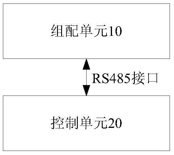
图1为根据本发明实施例的智能ODN设备的结构框图。如图1所示,该智能ODN设备包括:组配单元10、控制单元20,组配单元10与控制单元20通过RS485接口连接。FIG. 1 is a structural block diagram of an intelligent ODN device according to an embodiment of the present invention. As shown in FIG. 1 , the intelligent ODN device includes: an assembly unit 10 and a control unit 20 , and the assembly unit 10 and the control unit 20 are connected through an RS485 interface.
基于上述结构特征,智能ODN设备内部的组配单元和控制单元之间通过统一的RS485接口进行通信连接,并且,由于智能ODN设备和智能管理终端之间采用I2接口,而I2接口为RS485接口,因此,有利于实现模块的直接对接,避免多余的协议转换;并且,由于规定了ODN设备内部接口的统一标准,因此,有利于大规模商用推广。Based on the above structural features, the assembly unit and the control unit inside the intelligent ODN device are connected through a unified RS485 interface, and since the I2 interface is used between the intelligent ODN device and the intelligent management terminal, and the I2 interface is an RS485 interface, Therefore, it is beneficial to realize the direct connection of modules and avoid redundant protocol conversion; and, since the unified standard of the internal interface of the ODN device is specified, it is beneficial to large-scale commercial promotion.
在一个优选实施例中,如图2所示,控制单元20,包括:管理模块200,用于实现智能ODN设备的对外通信功能,以及对级联模块和组配单元进行管理;级联模块202,用于为所述组配单元和所述管理模块分别提供第一RS485接口和第二RS485接口;组配单元10通过第一RS485接口与级联模块202连接,管理模块200通过第二RS485接口与级联模块202连接。In a preferred embodiment, as shown in FIG. 2 , the control unit 20 includes: a management module 200 for implementing the external communication function of the intelligent ODN device and managing the cascading modules and the assembling units; the cascading module 202 , used to provide a first RS485 interface and a second RS485 interface for the assembly unit and the management module respectively; the assembly unit 10 is connected to the cascade module 202 through the first RS485 interface, and the management module 200 through the second RS485 interface Connect with the cascade module 202 .
在一个优选实施过程中,组配单元10在控制单元管理下提供I1接口,完成端口电子标签读取与端口定位指引的功能,并通过E1(即第一RS485接口)接口与级联模块202通信。E1接口两端为RJ45接头,接口为RS485信号电平,E1接口用以太网双绞线电缆连接组配单元的RJ45接头和级联模块的RJ45接头。E1接口有八根信号线,包括电源VCC、地GND、数据正端RS485_P、数据负端RS485_N、地址输入信号ADD_I、地址输出信号ADD_O六个信号,(参见图5左表)六个信号。RS485_P和RS485_N为一对RS485电平的差分数据线。In a preferred implementation process, the assembling unit 10 provides the I1 interface under the management of the control unit, completes the functions of port electronic label reading and port positioning guidance, and communicates with the cascading module 202 through the E1 (ie the first RS485 interface) interface. . Both ends of the E1 interface are RJ45 connectors, and the interface is RS485 signal level. The E1 interface uses an Ethernet twisted pair cable to connect the RJ45 connector of the assembly unit and the RJ45 connector of the cascade module. The E1 interface has eight signal lines, including power VCC, ground GND, data positive terminal RS485_P, data negative terminal RS485_N, address input signal ADD_I, address output signal ADD_O six signals, (see the left table of Figure 5) six signals. RS485_P and RS485_N are a pair of differential data lines of RS485 level.
在一个优选实施过程中,第一RS485接口包括:第一RS485接口包括:设置在组配单元10上的第一RJ45连接器,和设置于级联模块上的第二RJ45连接器,第一RJ45连接器和所述第二RJ45连接器通过以太网双绞线电缆连接;所述第二RS485接口包括:设置在管理模块200上的第三RJ45连接器,和设置于级联模块202上的第四RJ45连接器,第三RJ45连接器与第四RJ45连接器通过以太网双绞线电缆连接。在一个优选实施例中,以太网双绞线电缆为标准5类非屏蔽双绞线(Unshielded Twisted Paired,简称为UTP)或屏蔽双绞线(ShieldedTwisted Pair)。In a preferred implementation process, the first RS485 interface includes: the first RS485 interface includes: a first RJ45 connector arranged on the assembling unit 10, and a second RJ45 connector arranged on the cascading module, the first RJ45 connector The connector and the second RJ45 connector are connected by an Ethernet twisted pair cable; the second RS485 interface includes: a third RJ45 connector arranged on the management module 200, and a third RJ45 connector arranged on the cascading module 202 Four RJ45 connectors, the third RJ45 connector and the fourth RJ45 connector are connected by an Ethernet twisted pair cable. In a preferred embodiment, the Ethernet twisted pair cable is a standard Category 5 unshielded twisted pair (Unshielded Twisted Paired, UTP for short) or a shielded twisted pair (Shielded Twisted Pair).
级联模块202的实现方式有多种,在一个优选实施过程中,可以通过以下方式实现,级联模块202包括:印制电路板,以及设置在印制电路板上的第二RJ45连接器和第四RJ45连接器,其中,连接器用于提供上述第一RS485接口和上述第二RS485接口。There are various implementations of the cascading module 202. In a preferred implementation process, the cascading module 202 can be implemented in the following manner. The cascading module 202 includes: a printed circuit board, and a second RJ45 connector provided on the printed circuit board and A fourth RJ45 connector, wherein the connector is used to provide the above-mentioned first RS485 interface and the above-mentioned second RS485 interface.
为了便于对级联模块的版本进行管理,在印制电路板上可以还设置有遵循1-Wire标准的带电可擦可编程只读存储器(Electrically Erasable Programmable Read-OnlyMemory,简称为EEPROM),其中,EEPROM用于存储级联模块的识别信息,该识别信息可以包括但不限于:级联模块的版本信息和条码信息(即印制电路板的版本信息和条码信息)。优选地,管理模块通过第四RJ45连接器上的DATA_I/O信号端子与EEPROM的1-Wire管脚进行通信。在一个具体应用过程中,级联模块的表现形式如下:In order to facilitate the management of the version of the cascading module, an electrically erasable programmable read-only memory (Electrically Erasable Programmable Read-Only Memory, referred to as EEPROM for short) that follows the 1-Wire standard may also be provided on the printed circuit board, wherein, The EEPROM is used to store identification information of the cascading module, and the identification information may include, but is not limited to: version information and barcode information of the cascading module (ie, version information and barcode information of the printed circuit board). Preferably, the management module communicates with the 1-Wire pin of the EEPROM through the DATA_I/O signal terminal on the fourth RJ45 connector. In a specific application process, the expression of the cascade module is as follows:
级联模块在控制单元内部,提供与组配单元连接的E1接口,和与管理模块连接的E2接口(即第二RS485接口)。E2接口有八根信号线,不仅包括电源VCC、地GND、数据正端RS485_P、数据负端RS485_N、地址输入ADD_I五个信号,还可以包括数据DATA_IO一个信号。一个级联模块可连接一个或多个组配单元。RS485_P和RS485_N为一对RS485电平的差分数据线。DATA_IO为一根遵循1-Wire标准的双向数据线。级联模块通常为没有任何电子元器件的PCB印制电路板和连接器组成,但有时为了级联模块版本、条码管理方便,也可以在PCB印制电路板上安装一块遵循1-Wire标准的EEPROM存储器。The cascading module is inside the control unit, and provides an E1 interface connected to the assembly unit and an E2 interface (ie, a second RS485 interface) connected to the management module. The E2 interface has eight signal lines, including not only power VCC, ground GND, data positive terminal RS485_P, data negative terminal RS485_N, address input ADD_I five signals, but also a data DATA_IO signal. A cascade module can connect one or more assembly units. RS485_P and RS485_N are a pair of differential data lines of RS485 level. DATA_IO is a bidirectional data line following the 1-Wire standard. Cascading modules are usually composed of PCB printed circuit boards and connectors without any electronic components, but sometimes for the convenience of cascade module version and barcode management, a 1-Wire standard can also be installed on the PCB printed circuit board. EEPROM memory.
级联模块202可以为一个或多个。在为多个时,管理模块200与多个级联模块202之间的各个第二RS485接口可以是相互独立的,这样,便可以实现管理模块对级联模块的并行管理。类似地,组配单元10与多个级联模块202之间的各个第一RS485接口是相互独立的。Cascade modules 202 may be one or more. When there are more than one, each second RS485 interface between the management module 200 and the multiple cascading modules 202 may be independent of each other, so that parallel management of the cascading modules by the management module can be realized. Similarly, each first RS485 interface between the assembling unit 10 and the plurality of cascade modules 202 is independent of each other.
在一个应用过程中,管理模块200的表现形式如下:In an application process, the performance of the management module 200 is as follows:
管理模块200在控制单元内部,提供与级联模块连接的E2接口,与智能管理终端连接的I2接口,和与智能ODN管理系统连接的I3接口。一个管理模块可连接1到8个级联模块。管理模块可支持-48V直流或220V交流稳定供电,或者智能管理终端直流供电两种场景。如图6所示,管理模块中的电源模块用于将以下之一转换成管理模块内其他部件的供电电压(例如处理器的供电电压,或者所有RJ45连接器1、2、3,......,N的端子7、8的VCC电压等):外部设备提供的-48V直流或220V交流稳定供电;利用智能管理终端USB接口的5V直流供电;PoE(IEEE 802.3af以太网供电标准)接口的48V直流供电。Inside the control unit, the management module 200 provides an E2 interface connected with the cascade module, an I2 interface connected with the intelligent management terminal, and an I3 interface connected with the intelligent ODN management system. One management module can connect 1 to 8 cascade modules. The management module can support -48V DC or 220V AC stable power supply, or intelligent management terminal DC power supply two scenarios. As shown in Figure 6, the power module in the management module is used to convert one of the following into the supply voltage of other components in the management module (such as the power supply voltage of the processor, or all
管理模块把最多8个级联模块的E2接口串行RS485数据以并发或轮询方式,上传给管理模块内部的处理器处理。管理模块也支持通过模块内部的处理器的并行数据总线下发管理命令和对级联模块、组配单元更新软件版本。管理模块内部可同时处理某一路或多路串行RS485数据,然后分时地处理其他一路或多路RS485数据通过E2接口传到级联模块,或进一步通过E1接口传到组配单元。由此可见,管理模块内部可以不涉及对RS485数据的串行转换,提高数据传输处理的透明度和效率。The management module uploads the serial RS485 data of the E2 interface of up to 8 cascading modules to the processor inside the management module in a concurrent or polling manner. The management module also supports issuing management commands through the parallel data bus of the processor inside the module and updating the software version to the cascaded modules and assembly units. The management module can process one or more serial RS485 data at the same time, and then process other one or more RS485 data in a time-sharing manner and transmit it to the cascade module through the E2 interface, or further transmit it to the assembly unit through the E1 interface. It can be seen that the serial conversion of RS485 data is not involved in the management module, which improves the transparency and efficiency of data transmission processing.
由上述内容可知,本实施例中的上述第一RS485接口包括以下信号端子:电源VCC信号、地GND信号、数据正端信号、数据负端信号、地址输入ADD_I信号、地址输出ADD_O信号(具体可参见图5左表);上述第二RS485接口包括以下信号端子:电源VCC信号、地GND信号、数据正端信号、数据负端信号、地址输入ADD_I信号、数据输入输出DATA_IO信号(具体可参见图5右表)。DATA_IO信号遵循1-Wire标准。It can be seen from the above content that the above-mentioned first RS485 interface in this embodiment includes the following signal terminals: power supply VCC signal, ground GND signal, data positive terminal signal, data negative terminal signal, address input ADD_I signal, address output ADD_O signal (specifically can be Refer to the left table of Figure 5); the above-mentioned second RS485 interface includes the following signal terminals: power supply VCC signal, ground GND signal, data positive terminal signal, data negative terminal signal, address input ADD_I signal, data input and output DATA_IO signal (for details, please refer to the figure 5 right table). The DATA_IO signal follows the 1-Wire standard.
组配单元10为多个,每个10组配单元的通信地址通过与所述组配单元所对应RS485接口中的ADD信号线确定。There are multiple assembling units 10, and the communication address of each 10 assembling unit is determined by the ADD signal line in the RS485 interface corresponding to the assembling unit.
相关技术提供的标准RS485通信系统中,从机设置为不同的RS485地址。多机通信时,主机发送地址帧,所有从机收到地址帧后,都将接受的地址与本机的地址比较。对于地址相符的从机,把本机地址发回作为应答,建立与主机的通信;对于地址不符的从机,对主机随后发来的数据帧不予理睬。应用该系统需要对作为从机的组配单元设置不同的RS485地址,通常用组配单元内的拨码开关实现,可靠性差,容易出错。In the standard RS485 communication system provided by the related art, the slaves are set to different RS485 addresses. During multi-machine communication, the master sends an address frame, and all slaves will compare the received address with the address of the local machine after receiving the address frame. For the slaves whose addresses match, send the local address back as a response to establish communication with the master; for slaves whose addresses do not match, ignore the subsequent data frames sent by the master. The application of this system needs to set different RS485 addresses for the assembly unit as a slave, which is usually realized by the DIP switch in the assembly unit, which has poor reliability and is prone to errors.
或者改进型的RS485通信系统,N(N为自然数)个从机通过N对RS485差分信号线分别、独立地连接到主机,所有从机设置为相同的RS485地址。主机通过某一对RS485差分信号线访问其对应的某一个从机,然后主机切换到下一对RS485差分信号线访问其对应的下一个从机,直至主机访问完全部从机,再开始下一个循环。应用该系统需要为组配单元设置独立的N对RS485通信链路,而且要在作为主机的控制单元内增加RS485切换、轮询模块,系统较复杂,增加额外的切换软件开销和切换模块硬件功耗。Or an improved RS485 communication system, N (N is a natural number) slaves are respectively and independently connected to the master through N pairs of RS485 differential signal lines, and all slaves are set to the same RS485 address. The host accesses a corresponding slave through a pair of RS485 differential signal lines, and then the host switches to the next pair of RS485 differential signal lines to access its corresponding next slave until the host accesses all the slaves, and then starts the next one. cycle. To apply this system, it is necessary to set up an independent N-pair RS485 communication link for the assembly unit, and to add RS485 switching and polling modules in the control unit as the host. The system is more complicated, and additional switching software overhead and switching module hardware functions are added. consumption.
而在本实施例中,每个组配单元的通信地址通过与组配单元所对应RS485接口中的ADD信号线确定,即:In this embodiment, the communication address of each assembly unit is determined by the ADD signal line in the RS485 interface corresponding to the assembly unit, that is:
管理模块是RS485通信系统的主机,组配单元是RS485通信系统的从机,级联模块是RS485通信系统中连接主机和从机RS485信号线的节点模块。本实施例所述的RS485通信系统中作为从机的组配单元通过地址ADD信号设置为不同的RS485地址,其中任一个级联模块和其相连接的管理模块与组配单元的RS485差分线直接在级联模块中对接,即所有的RS485_P信号连接为一个网络,所有的RS485_N连接为另一个网络。管理模块连接一个或多个级联模块,管理模块与级联模块之间的E2接口是相互独立的,管理模块并行处理一个或多个级联模块RS485数据。The management module is the host of the RS485 communication system, the assembly unit is the slave of the RS485 communication system, and the cascade module is the node module that connects the RS485 signal line between the host and the slave in the RS485 communication system. In the RS485 communication system described in this embodiment, the assembly unit serving as the slave is set to a different RS485 address through the address ADD signal, and any cascading module and its connected management module are directly connected to the RS485 differential line of the assembly unit. Docking in the cascade module, that is, all RS485_P signals are connected as one network, and all RS485_N are connected as another network. The management module is connected to one or more cascade modules, the E2 interface between the management module and the cascade modules is independent of each other, and the management module processes the RS485 data of one or more cascade modules in parallel.
为了更好地理解上述实施例,以下结合优选实施例详细说明。In order to better understand the above embodiments, the following detailed description is given in conjunction with the preferred embodiments.
以下实施例提出一种基于RS485通信系统的智能ODN设备。因为I2接口规定是RJ45接头的RS485接口,所以智能ODN设备内部单元之间采用RS485接口有利于模块直接对接,避免多余的协议转换;统一的RJ45接头方便使用统一的以太网线作为内部模块单元之间的通信线缆,避免多种线缆用于一个系统中。The following embodiment proposes an intelligent ODN device based on the RS485 communication system. Because the I2 interface is stipulated as the RS485 interface of the RJ45 connector, the use of the RS485 interface between the internal units of the intelligent ODN equipment is conducive to the direct connection of the modules and avoids redundant protocol conversion; the unified RJ45 connector is convenient to use the unified Ethernet cable as the internal module unit. communication cables, avoiding the use of multiple cables in a system.
为实现上述目的,如图3所示,本实施例提供的智能ODN设备,包括EODN系统(EasyODN)组配单元、电子标签载体,还包括控制单元中的管理模块、级联模块,组配单元与级联模块之间的E1接口,和级联模块与管理模块之间的E2接口。E1和E2接口基于RS485协议通信。In order to achieve the above purpose, as shown in FIG. 3 , the intelligent ODN device provided by this embodiment includes an EODN system (EasyODN) assembly unit, an electronic label carrier, and also includes a management module, a cascade module, and an assembly unit in the control unit. The E1 interface between the expansion module and the E2 interface between the expansion module and the management module. The E1 and E2 interfaces communicate based on the RS485 protocol.
组配单元内部包含一个处理器和一个RJ45连接器,参考图4所示。组配单元在控制单元管理下提供I1接口,完成端口电子标签读取与端口定位指引的功能,并通过E1接口与级联模块通信。E1接口两端为RJ45接头,用标准以太网线作为通信介质,E1接口用以太网线连接组配单元的RJ45连接器和级联模块的RJ45连接器。E1接口有八根信号端子,参考图5中的左面表格,信号端子定义以组配单元为准说明,包括端子7、8的电源VCC、端子2、6的地GND、端子4的数据正端RS485_P、端子5的数据负端RS485_N四个信号,还包括端子1的地址输入信号ADD_I,端子3的地址输出信号ADD_O。RS485_P和RS485_N为一对差分双向数据线,ADD_I和ADD_O为以GND作为参考的单端信号。电源VCC和地GND由上级级联模块提供,地是整个组配单元的信号参考平面。优选地,每个组配单元可通过12个I1接口连接12个电子标签载体。The assembly unit contains a processor and an RJ45 connector, as shown in Figure 4. The assembly unit provides the I1 interface under the management of the control unit, completes the functions of port electronic label reading and port positioning guidance, and communicates with the cascade module through the E1 interface. Both ends of the E1 interface are RJ45 connectors, and a standard Ethernet cable is used as the communication medium. The E1 interface uses an Ethernet cable to connect the RJ45 connector of the assembly unit and the RJ45 connector of the cascade module. The E1 interface has eight signal terminals. Refer to the table on the left in Figure 5. The definition of the signal terminals is based on the assembly unit, including the power supply VCC of terminals 7 and 8, the ground GND of
智能ODN设备初始化时,管理模块通过E2接口级联模块的RJ45连接器0端子1发送1个地址配置脉冲ADD1,脉冲有效时间为T1,这个地址配置脉冲传到级联模块的RJ45连接器1端子1,然后再传到组配单元1的RJ45连接器1端子1,最后传到组配单元1的处理器1。处理器1收到这个地址配置脉冲后,认为本组配单元1的RS485地址为1,再发送连续2个地址配置脉冲到组配单元1的RJ45连接器1端子3。这2个脉冲有效时间都为T1,2个脉冲时间间隔为T2,整个脉冲时间为2*T1+T2。组配单元1发出的地址配置脉冲经过级联模块的RJ45连接器1端子3成为地址配置脉冲ADD2,然后经过RJ45连接器2端子1,和组配单元2的RJ45连接器2端子1,传到组配单元2的处理器2。处理器2收到这个地址配置脉冲后,认为本组配单元2的RS485地址为2,再发送连续3个地址配置脉冲到组配单元2的RJ45连接器2端子3。这3个脉冲有效时间都为T1,每个脉冲时间间隔为T2,整个脉冲时间为3*T1+2*T2。以此类推,经过智能ODN设备初始化后,组配单元3的RS485地址为3,组配单元N的RS485地址为N,组配单元N收到的N个地址配置脉冲,整个脉冲时间为N*T1+(N-1)*T2。When the intelligent ODN device is initialized, the management module sends an address configuration pulse ADD1 through the RJ45 connector 0
智能ODN设备初始化前,管理模块为RS485通信系统的主机,组配单元为RS485通信系统的从机。组配单元只接收RS485信息,不主动发送RS485信息,等待管理模块下发地址配置脉冲,从收到第1个地址配置脉冲开始计算脉冲数,计数时间T3为大于N*(T1+T2)的某个时间,超过T3时间组配单元上的处理器则认为计数超时,本组配单元的RS485地址为本次计数时间T3内计算得到的脉冲数。智能ODN设备初始化后,管理模块分配完RS485地址,组配单元和管理模块建立正常RS485通信系统。组配单元内的处理器通过I1接口扫描端口电子标签,经过处理后通过RJ45连接器,以太网线缆的E1接口上传到级联模块。Before the initialization of the intelligent ODN device, the management module is the master of the RS485 communication system, and the assembly unit is the slave of the RS485 communication system. The assembly unit only receives RS485 information, does not actively send RS485 information, waits for the management module to issue address configuration pulses, and counts the number of pulses from receiving the first address configuration pulse, and the counting time T3 is greater than N*(T1+T2) At a certain time, if the time exceeds T3, the processor on the assembly unit considers the count time-out, and the RS485 address of this assembly unit is the number of pulses calculated within the count time T3. After the intelligent ODN device is initialized, the management module assigns the RS485 address, and the assembly unit and the management module establish a normal RS485 communication system. The processor in the assembly unit scans the port electronic label through the I1 interface, and after processing, it is uploaded to the cascade module through the RJ45 connector and the E1 interface of the Ethernet cable.
级联模块在控制单元内部,提供与组配单元连接的E1接口,和与管理模块连接的E2接口。E2接口有八根信号线,E2接口级联模块一段为RJ45连接器0,有八根信号端子,参考图5中的右面表格,信号端子定义以级联模块为准说明,包括端子7、8的电源VCC、端子2、6的地GND、端子4的数据正端RS485_P、端子5的数据负端RS485_N四个信号、端子1的地址输入信号ADD_I,还包括端子3的1-Wire双向信号DATA_IO。RS485_P和RS485_N为一对差分双向数据线,ADD_I和DATA_IO为以GND作为参考的单端信号。电源VCC和地GND由上级管理模块提供,地是整个组配单元的信号参考平面。每个级联模块可通过N个E1接口连接N个组配单元。一般本发明实施例所述的级联模块为只包含PCB、RJ45连接器的无源模块,但是也可以选择在级联模块内安装1-Wire EEPROM。1-Wire EEPROM内部存储级联模块版本等信息,管理模块通过RJ45连接器0上的端子3的DATA_IO信号与端子2、6的GND地访问1-Wire EEPROM信息,进行级联模块版本管理。The cascading module is inside the control unit, and provides an E1 interface connected to the assembly unit and an E2 interface connected to the management module. The E2 interface has eight signal lines, the first section of the E2 interface cascade module is RJ45 connector 0, and there are eight signal terminals. Refer to the table on the right in Figure 5. The definition of signal terminals is based on the cascade module, including terminals 7 and 8. VCC, ground GND of
管理模块在控制单元内部,提供与级联模块连接的E2接口,与智能管理终端连接的I2接口,和与智能ODN管理系统连接的I3接口。一个管理模块可连接1到M(M为自然数)个级联模块。如图6所示,管理模块内部包括处理器、电源模块和M个RJ45连接器。管理模块的电源模块可支持-48V直流或220V交流稳定供电,或者智能管理终端直流供电两种场景。管理模块的处理器分时地通过管理模块的RJ45连接器E2接口访问下级的级联模块,并进一步地通过E1接口访问组配单元。E2接口的RS485串口数据不经过协议转换,直接由管理模块的处理器处理,节省协议转换软件开销,提高了处理效率。管理模块也支持通过模块内部的处理器下发管理命令,对级联模块和组配单元更新软件版本。The management module is inside the control unit, and provides an E2 interface connected with the cascade module, an I2 interface connected with the intelligent management terminal, and an I3 interface connected with the intelligent ODN management system. One management module can connect 1 to M (M is a natural number) cascaded modules. As shown in Figure 6, the management module includes a processor, a power supply module and M RJ45 connectors. The power module of the management module can support -48V DC or 220V AC stable power supply, or the intelligent management terminal DC power supply two scenarios. The processor of the management module accesses the lower-level cascade module through the E2 interface of the RJ45 connector of the management module in a time-sharing manner, and further accesses the assembly unit through the E1 interface. The RS485 serial port data of the E2 interface is directly processed by the processor of the management module without protocol conversion, which saves the protocol conversion software overhead and improves the processing efficiency. The management module also supports issuing management commands through the processor inside the module to update the software version of the cascade modules and assembly units.
优选的,如果智能ODN设备满配1152芯光纤,本发明实施例所述的系统包括1152个电子标签载体,1个管理模块,8个级联模块,和96个组配单元,RS485通信系统包括管理模块和级联模块之间的8个E2接口,级联模块和组配单元之间的96个E1接口。如果智能ODN设备满配576芯光纤,本发明实施例所述的系统有2种组网结构。第一种包括576个电子标签载体,1个管理模块,4个级联模块,和48个组配单元,RS485通信系统包括管理模块和级联模块之间的4个E2接口,级联模块和组配单元之间的48个E1接口,每个级联模块连接12个组配单元。第二种包括576个电子标签载体,1个管理模块,6个级联模块,和48个组配单元,RS485通信系统包括管理模块和级联模块之间的6个E2接口,级联模块和组配单元之间的48个E1接口,每个级联模块连接8个组配单元。Preferably, if the intelligent ODN device is fully equipped with 1152 optical fibers, the system described in this embodiment of the present invention includes 1152 electronic label carriers, 1 management module, 8 cascade modules, and 96 assembly units, and the RS485 communication system includes 8 E2 interfaces between the management module and the cascading module, 96 E1 interfaces between the cascading module and the assembly unit. If the intelligent ODN device is fully equipped with 576-core optical fibers, the system described in the embodiment of the present invention has two networking structures. The first type includes 576 electronic label carriers, 1 management module, 4 cascading modules, and 48 assembly units. The RS485 communication system includes 4 E2 interfaces between the management module and the cascading module, and the cascading modules and There are 48 E1 interfaces between assembling units, and each cascading module is connected to 12 assembling units. The second type includes 576 electronic label carriers, 1 management module, 6 cascading modules, and 48 assembly units. The RS485 communication system includes 6 E2 interfaces between the management module and the cascading module. There are 48 E1 interfaces between assembling units, and each cascading module is connected to 8 assembling units.
标准RS485通信系统中,从机设置为不同的RS485地址。多机通信时,主机发送地址帧,所有从机收到地址帧后,都将接受的地址与本机的地址比较。对于地址相符的从机,把本机地址发回作为应答,建立与主机的通信;对于地址不符的从机,对主机随后发来的数据帧不予理睬。本RS485通信系统中控制单元是主机,组配单元是从机。本发明实施例所述的RS485通信系统巧妙地在级联模块中设置地址输入,地址输出信号线,实现对组配单元的地址配置,使RS485通信系统中的各个组配单元为不同的RS485地址。In the standard RS485 communication system, the slaves are set to different RS485 addresses. During multi-machine communication, the master sends an address frame, and all slaves will compare the received address with the address of the local machine after receiving the address frame. For the slaves whose addresses match, send the local address back as a response to establish communication with the master; for slaves whose addresses do not match, ignore the subsequent data frames sent by the master. In this RS485 communication system, the control unit is the master, and the assembly unit is the slave. The RS485 communication system according to the embodiment of the present invention cleverly sets address input and address output signal lines in the cascade module to realize the address configuration of the assembly unit, so that each assembly unit in the RS485 communication system has different RS485 addresses .
综合以上所述,本发明实施例的管理模块与级联模块是相互独立的E2接口,不但可以同时下发软件指令,而且可以并行地采集到电子标签载体的插拔告警,满足运营商对于组配单元端口上电子标签载体状态变化响应时间要求,即-48V直流或220V交流稳定供电场景下响应时间小于3秒,智能管理终端供电场景下响应时间小于2秒。To sum up the above, the management module and the cascading module in the embodiment of the present invention are independent E2 interfaces, which can not only issue software instructions at the same time, but also collect the plugging and unplugging alarms of the electronic label carrier in parallel, which satisfies the operator's requirements for the group. The response time of the state change of the electronic label carrier on the port of the distribution unit is required, that is, the response time of the -48V DC or 220V AC stable power supply scenario is less than 3 seconds, and the response time of the intelligent management terminal power supply scenario is less than 2 seconds.
标准RS485协议是需要对总线上所有的设备设置节点地址,比如现在有些智能ODN设备的组配单元采用拨码开关设置节点地址,或者用软件把节点地址烧在组配单元的EEPROM或控制器内存中。采用拨码开关方法会造成可靠性问题,现场手工设置拨码开关会有人为错误。采用软件设置方法会造成软件版本不一致问题,不方便管理。本发明实施例所述基于RS485的通信系统,系统中的级联模块与组配单元都不需要设置单独的RS485节点地址,便于级联模块和组配单元统一软硬件配置,有利于大规模生产,提高设备可靠性。并且本发明实施例首次提出智能ODN设备的内部RS485通信系统架构,有利于各个通信设备厂商的智能ODN设备模块之间的互联互通。本发明实施例中的级联模块无软件开销,硬件功耗为零,极大地提升了智能ODN设备的性能。The standard RS485 protocol needs to set the node address for all the devices on the bus. For example, the assembly unit of some intelligent ODN devices uses the DIP switch to set the node address, or use software to burn the node address in the EEPROM or controller memory of the assembly unit. middle. Using the DIP switch method will cause reliability problems, and manual setting of the DIP switch on site will result in human error. Using the software setting method will cause inconsistent software versions, which is inconvenient to manage. In the RS485-based communication system according to the embodiment of the present invention, the cascade module and the assembly unit in the system do not need to set a separate RS485 node address, which facilitates the unified software and hardware configuration of the cascade module and the assembly unit, and is beneficial to mass production. , improve equipment reliability. In addition, the embodiment of the present invention proposes the internal RS485 communication system architecture of the intelligent ODN device for the first time, which is beneficial to the interconnection and intercommunication between the intelligent ODN device modules of various communication device manufacturers. The cascading module in the embodiment of the present invention has no software overhead and zero hardware power consumption, which greatly improves the performance of the intelligent ODN device.
采用本发明实施例所述的系统,与现有的智能ODN设备相比,采用统一的RS485接口的方法,解决了各个通信设备厂商内部接口不统一的问题,有助于各厂商模块的对接。不需要为每个组配单元上安装拨码开关,节省采购成本,增强了设备可靠性。生产过程中,不需要人工设置拨码开关,方便各厂商模块的对接和组配单元批量生产,节省生产成本。并且,一般本RS485系统应用中的级联模块为没有任何电子元器件的无源模块,降低了整个智能ODN设备功耗。特殊应用时在级联模块增加一个基于1-Wire标准的EEPROM,智能ODN设备正常工作时,包含该EEPROM的级联模块功耗为零;只有当智能ODN设备上电初始化,管理模块读取级联模块EEPROM信息时,才消耗极少量功耗。该特殊应用增加了级联模块的在线版本、条形码管理能力。Compared with the existing intelligent ODN equipment, the system according to the embodiment of the present invention adopts a unified RS485 interface method, which solves the problem that the internal interfaces of various communication equipment manufacturers are not unified, and facilitates the connection of modules of various manufacturers. There is no need to install a DIP switch on each assembly unit, which saves procurement costs and enhances equipment reliability. In the production process, there is no need to manually set the DIP switches, which facilitates the connection of modules of various manufacturers and the mass production of assembly units, and saves production costs. Moreover, generally, the cascade module in the application of this RS485 system is a passive module without any electronic components, which reduces the power consumption of the entire intelligent ODN device. In special applications, an EEPROM based on the 1-Wire standard is added to the cascading module. When the smart ODN device is working normally, the power consumption of the cascading module including the EEPROM is zero; only when the smart ODN device is powered on and initialized, the management module reads the level. When connecting the module EEPROM information, it consumes a very small amount of power consumption. This special application adds an online version of the cascading module, barcode management capabilities.
上述为本发明较佳的实施方式,但本发明的实施方式并不受上述内容的限制,其他的任何未背离本发明的精神实质与原理下所作的改变、修饰、替代、组合、简化,均应为等效的置换方式,都包含在本发明的保护范围之内。例如对于N(N为自然数)个电子标签载体的N芯智能ODN设备可以有多种级联模块和组配单元的组合方式,可以不必完全按照上述发明中的1个管理模块,8个级联模块,和96个组配单元组合方式。组配单元的RS485地址获得可以不是处理器计算地址配置脉冲个数,而是采用地址编码的方式获得。比如有12个组配单元,可以编码为4位RS485地址,即从二进制地址0001到地址1100。管理模块下发地址配置脉冲0001到E1接口的ADD_I信号给第1个组配单元,第1个组配单元RS485地址即为0001。然后第1个组配单元发送地址配置脉冲0002到E1接口的ADD_O信号给第2个组配单元,第2个组配单元RS485地址即为0002,依次类推。图5中RJ45连接器的信号端子顺序是智能ODN设备的RS485通信系统中较优的排列,也可以改为其他端子顺序,都包含在本发明的保护范围内。The above are the preferred embodiments of the present invention, but the embodiments of the present invention are not limited by the above-mentioned contents, and any other changes, modifications, substitutions, combinations, and simplifications made without departing from the spirit and principle of the present invention are all Should be equivalent replacement manners, all are included within the protection scope of the present invention. For example, for an N-core smart ODN device with N (N is a natural number) electronic label carrier, there may be various combinations of cascading modules and assembling units, and it is not necessary to completely follow the one management module in the above invention, 8 cascaded modules, and 96 combination units. The RS485 address of the assembly unit can be obtained not by the processor calculating the number of address configuration pulses, but by address coding. For example, there are 12 assembly units, which can be encoded as 4-bit RS485 addresses, that is, from binary address 0001 to address 1100. The management module sends the address configuration pulse 0001 to the ADD_I signal of the E1 interface to the first assembly unit, and the RS485 address of the first assembly unit is 0001. Then the first assembly unit sends the address configuration pulse 0002 to the ADD_O signal of the E1 interface to the second assembly unit, and the RS485 address of the second assembly unit is 0002, and so on. The sequence of signal terminals of the RJ45 connector in FIG. 5 is an optimal arrangement in the RS485 communication system of the intelligent ODN device, and it can also be changed to other terminal sequences, which are all included in the protection scope of the present invention.
以上所述仅为本发明的优选实施例而已,并不用于限制本发明,对于本领域的技术人员来说,本发明可以有各种更改和变化。凡在本发明的精神和原则之内,所作的任何修改、等同替换、改进等,均应包含在本发明的保护范围之内。The above descriptions are only preferred embodiments of the present invention, and are not intended to limit the present invention. For those skilled in the art, the present invention may have various modifications and changes. Any modification, equivalent replacement, improvement, etc. made within the spirit and principle of the present invention shall be included within the protection scope of the present invention.
Claims (11)
Priority Applications (2)
| Application Number | Priority Date | Filing Date | Title |
|---|---|---|---|
| CN201410555247.XA CN105577415B (en) | 2014-10-17 | 2014-10-17 | Intelligent optical distribution network equipment |
| PCT/CN2015/082103 WO2016058405A1 (en) | 2014-10-17 | 2015-06-23 | Intelligent optical distribution network device |
Applications Claiming Priority (1)
| Application Number | Priority Date | Filing Date | Title |
|---|---|---|---|
| CN201410555247.XA CN105577415B (en) | 2014-10-17 | 2014-10-17 | Intelligent optical distribution network equipment |
Publications (2)
| Publication Number | Publication Date |
|---|---|
| CN105577415A CN105577415A (en) | 2016-05-11 |
| CN105577415B true CN105577415B (en) | 2020-02-14 |
Family
ID=55746089
Family Applications (1)
| Application Number | Title | Priority Date | Filing Date |
|---|---|---|---|
| CN201410555247.XA Active CN105577415B (en) | 2014-10-17 | 2014-10-17 | Intelligent optical distribution network equipment |
Country Status (2)
| Country | Link |
|---|---|
| CN (1) | CN105577415B (en) |
| WO (1) | WO2016058405A1 (en) |
Families Citing this family (1)
| Publication number | Priority date | Publication date | Assignee | Title |
|---|---|---|---|---|
| CN111131931B (en) * | 2019-12-04 | 2021-09-28 | 南京邮电大学 | Parallel architecture optical fiber management system and method |
Citations (3)
| Publication number | Priority date | Publication date | Assignee | Title |
|---|---|---|---|---|
| CN2636457Y (en) * | 2003-06-22 | 2004-08-25 | 华为技术有限公司 | Transmission cable |
| CN201698216U (en) * | 2010-04-21 | 2011-01-05 | 桂林理工大学 | A real-time configuration interface circuit for fieldbus modules |
| CN104022963A (en) * | 2014-01-02 | 2014-09-03 | 烽火通信科技股份有限公司 | A communication method and device with a plurality of communication modes coexisting |
Family Cites Families (8)
| Publication number | Priority date | Publication date | Assignee | Title |
|---|---|---|---|---|
| CN102035252A (en) * | 2009-09-25 | 2011-04-27 | 浙江昌泰科技股份有限公司 | Distribution electrical energy monitoring terminal |
| FR2966996A1 (en) * | 2010-10-27 | 2012-05-04 | France Telecom | DATA PROCESSING FOR THE MANAGEMENT OF SLEEP |
| CN102480654A (en) * | 2010-11-30 | 2012-05-30 | 中兴通讯股份有限公司 | Optical-fiber network node terminal and passive optical-fiber network (PON) system |
| US20130215417A1 (en) * | 2011-08-19 | 2013-08-22 | Jan Diestelmans | System and method for determining optical distribution network connectivity |
| CN102685037B (en) * | 2012-06-08 | 2015-12-02 | 汕头市易普联科技有限公司 | Gateway device |
| CN102739488B (en) * | 2012-06-15 | 2014-12-31 | 烽火通信科技股份有限公司 | CAN (controller area network) bus-based communication method in intelligent ODN (optical distribution network) system |
| CN103560908B (en) * | 2013-10-23 | 2017-01-04 | 江苏亨通光网科技有限公司 | A kind of centralized-control intelligent ODN electronic label machine disc managing circuit |
| CN103763134A (en) * | 2014-01-07 | 2014-04-30 | 烽火通信科技股份有限公司 | Dual-control device and method based on intelligent terminal |
-
2014
- 2014-10-17 CN CN201410555247.XA patent/CN105577415B/en active Active
-
2015
- 2015-06-23 WO PCT/CN2015/082103 patent/WO2016058405A1/en not_active Ceased
Patent Citations (3)
| Publication number | Priority date | Publication date | Assignee | Title |
|---|---|---|---|---|
| CN2636457Y (en) * | 2003-06-22 | 2004-08-25 | 华为技术有限公司 | Transmission cable |
| CN201698216U (en) * | 2010-04-21 | 2011-01-05 | 桂林理工大学 | A real-time configuration interface circuit for fieldbus modules |
| CN104022963A (en) * | 2014-01-02 | 2014-09-03 | 烽火通信科技股份有限公司 | A communication method and device with a plurality of communication modes coexisting |
Also Published As
| Publication number | Publication date |
|---|---|
| CN105577415A (en) | 2016-05-11 |
| WO2016058405A1 (en) | 2016-04-21 |
Similar Documents
| Publication | Publication Date | Title |
|---|---|---|
| CN105119849B (en) | A kind of exchange board structure and the data managing method applied to exchange board structure | |
| CN208188815U (en) | BMC module system | |
| CN115996204B (en) | Out-of-band Ethernet interface switching device, multi-node server system and server equipment | |
| CN106873541A (en) | A kind of EtherCAT Distributed Servo kinetic control systems based on DSP | |
| CN102724093A (en) | Advanced telecommunications computing architecture (ATCA) machine frame and intelligent platform management bus (IPMB) connection method thereof | |
| CN109558158B (en) | Device and method for updating FPGA and DSP programs based on network | |
| WO2024212744A1 (en) | Server, heterogeneous device, and data processing apparatus thereof | |
| CN112087359B (en) | Serial communication system | |
| CN109561032B (en) | Switch module reaches switch including it | |
| CN111538689A (en) | Heterogeneous multi-channel PCIE riser card at both ends | |
| CN108647180A (en) | A kind of arithmetic system and corresponding electronic equipment | |
| CN102880235B (en) | Single-board computer based on loongson 2F central processing unit (CPU) as well as reset management and using method of single-board computer | |
| CN203554493U (en) | Server remote management interface system | |
| CN105577415B (en) | Intelligent optical distribution network equipment | |
| CN214042097U (en) | PLC serial port communication extension module capable of customizing protocol | |
| CN120762899A (en) | Memory pooling system and control method, power-on method, device, and electronic device thereof | |
| CN109508313A (en) | A kind of dual redundant 1553B bus protocol module based on CPCI-E | |
| CN106161169A (en) | A kind of multi-host network exchange system | |
| CN111813732A (en) | Multi-machine communication method based on serial port communication of single chip microcomputer | |
| CN111443651A (en) | System for function module extension through Ethernet backboard bus | |
| CN213122967U (en) | RS485 signal sharing device | |
| CN110022255A (en) | The ubiquitous electric power platform of internet of things of modularization based on mixing communication network data exchange | |
| CN208905017U (en) | A kind of communication master-salve station mainboard based on Cortex-M3 processor | |
| CN210380893U (en) | Topology board card and topology system | |
| CN115303203A (en) | Debugging board of vehicle-mounted controller, vehicle-mounted controller mainboard and vehicle |
Legal Events
| Date | Code | Title | Description |
|---|---|---|---|
| C06 | Publication | ||
| PB01 | Publication | ||
| SE01 | Entry into force of request for substantive examination | ||
| SE01 | Entry into force of request for substantive examination | ||
| GR01 | Patent grant | ||
| GR01 | Patent grant |