CN105286904B - A breast machine compression device - Google Patents
A breast machine compression device Download PDFInfo
- Publication number
- CN105286904B CN105286904B CN201510604669.6A CN201510604669A CN105286904B CN 105286904 B CN105286904 B CN 105286904B CN 201510604669 A CN201510604669 A CN 201510604669A CN 105286904 B CN105286904 B CN 105286904B
- Authority
- CN
- China
- Prior art keywords
- pulley
- gear
- compression
- manual unlocking
- timing belt
- Prior art date
- Legal status (The legal status is an assumption and is not a legal conclusion. Google has not performed a legal analysis and makes no representation as to the accuracy of the status listed.)
- Expired - Fee Related
Links
Images


Landscapes
- Apparatus For Radiation Diagnosis (AREA)
Abstract
Description
技术领域technical field
本发明涉及乳腺钼靶X射线机领域,尤其涉及的是一种乳腺机压迫装置。The invention relates to the field of mammography mammography X-ray machines, in particular to a breast machine compression device.
背景技术Background technique
乳腺机压迫装置在乳腺钼靶X线检查具有相当重要的作用,其设计的好坏关系到获取的影像质量。The breast compression device plays a very important role in mammography, and the quality of its design is related to the quality of the obtained images.
乳腺机压迫装置一般使用电力驱动压迫器做直线运动,所使用的传动方式包括有齿轮传动、链传动等。市场上的压迫装置大多具有解锁功能,其解锁机构一般有翻转式压迫板、电动驱动、或双向逆止器手动调节等。Breast machine compression devices generally use electric drive compression devices to do linear motion, and the transmission methods used include gear transmission, chain transmission, etc. Most of the compression devices on the market have an unlocking function, and the unlocking mechanism generally includes a flip-up compression plate, an electric drive, or a manual adjustment of a two-way backstop.
使用齿轮传动或链传动虽然可以获得较精密的传动精度,但其具有较大的重量,整个系统的结构也较复杂,势必增加主轴旋转驱动装置的负担。另外,翻转式压迫板虽然在断电的时候可以手动解锁,但是操作起来比较麻烦,需要培训出熟练的临床操作医生;电动驱动是靠脉冲发生器驱动解锁驱动装置的,需要配备专门的电池防止电源断电的情况下不能解锁,从而给用户带来损害;双向逆止器造价较高,依靠楔形面锁定,可靠性较差。Although the use of gear transmission or chain transmission can obtain more precise transmission accuracy, it has a large weight and a complex structure of the entire system, which is bound to increase the burden on the spindle rotation drive device. In addition, although the flip-up compression plate can be manually unlocked when the power is off, it is cumbersome to operate, and skilled clinical operators need to be trained; the electric drive relies on a pulse generator to drive the unlocking drive device, which needs to be equipped with a special battery to prevent In the case of power failure, it cannot be unlocked, thus causing damage to the user; the two-way backstop is expensive and relies on wedge-shaped surface locking, which has poor reliability.
因此,相关技术还有待于改进和发展。Therefore, the related technology still needs to be improved and developed.
发明内容SUMMARY OF THE INVENTION
本发明要解决的技术问题在于,针对现有技术的上述缺陷,提供一种乳腺机压迫装置,其传动精度高,重量轻,可靠性高,反应灵敏,解锁方便,且有效降低成本,满足临床使用要求。The technical problem to be solved by the present invention is, in view of the above-mentioned defects of the prior art, to provide a breast machine compression device, which has high transmission precision, light weight, high reliability, sensitive response, convenient unlocking, and effectively reduces costs, and meets clinical needs. Requirements.
本发明解决技术问题所采用的技术方案如下:The technical scheme adopted by the present invention to solve the technical problem is as follows:
一种乳腺机压迫装置,包括压迫面板、导轨、设置于导轨上并可沿导轨上下活动的滑块座以及与滑块座固定连接的压迫支架;其还包括:A breast machine compression device, comprising a compression panel, a guide rail, a slider seat arranged on the guide rail and movable up and down along the guide rail, and a compression bracket fixedly connected with the slider seat; it also includes:
第一传动装置,所述第一传动装置包括第一带轮、第二带轮以及第一同步带,所述第一带轮与第二带轮通过第一同步带连接,所述第一同步带与滑块座接触并带动滑块座上下活动;a first transmission device, the first transmission device includes a first pulley, a second pulley and a first timing belt, the first pulley and the second pulley are connected by a first timing belt, the first timing belt The belt contacts the slider seat and drives the slider seat to move up and down;
与第一带轮连接的用于驱动第一带轮转动的驱动装置;a driving device connected with the first pulley for driving the first pulley to rotate;
与驱动装置连接的用于在断电时对驱动装置制动的制动器;a brake connected to the drive for braking the drive in the event of a power failure;
设置于压迫支架上的用于在断电时控制压迫支架上下活动的手动解锁装置;A manual unlocking device arranged on the compression bracket for controlling the up and down movement of the compression bracket when the power is turned off;
以及,设置于手动解锁装置上的用于在通电状态下限制手动解锁装置活动的阻尼器。And, a damper provided on the manual unlocking device for restricting the movement of the manual unlocking device in a power-on state.
所述的一种乳腺机压迫装置中,所述驱动装置包括电机、与电机的输出轴连接的第一齿轮以及与第一齿轮相啮合的第二齿轮,所述第二齿轮通过连接轴与第一带轮同轴连接。In the described breast machine compression device, the driving device includes a motor, a first gear connected with the output shaft of the motor, and a second gear meshed with the first gear, the second gear is connected to the first gear through the connecting shaft. One wheel coaxial connection.
所述的一种乳腺机压迫装置中,所述驱动装置还包括扭矩限制器,所述扭矩限制器设置于电机与第一齿轮之间。In the breast machine compression device, the driving device further includes a torque limiter, and the torque limiter is arranged between the motor and the first gear.
所述的一种乳腺机压迫装置中,所述电机与第一齿轮通过第一联轴器连接。In the aforementioned compression device for a breast machine, the motor and the first gear are connected through a first coupling.
所述的一种乳腺机压迫装置中,所述压迫装置还包括用于输出检测压迫支架升降高度的电信号的电位器以及与电位器连接的用于带动所述电位器转动的第二传动装置。In the breast machine compression device, the compression device further includes a potentiometer for outputting an electrical signal for detecting the height of the compression bracket, and a second transmission device connected with the potentiometer for driving the potentiometer to rotate. .
所述的一种乳腺机压迫装置中,所述第二传动装置包括第三带轮、第四带轮以及第二同步带,所述第三带轮与第四带轮通过第二同步带连接,所述第三带轮与电位器通过第二联轴器连接,所述滑块座与第二同步带固定连接。In the breast machine compression device, the second transmission device includes a third pulley, a fourth pulley and a second timing belt, and the third pulley and the fourth pulley are connected by the second timing belt. , the third pulley is connected with the potentiometer through the second coupling, and the slider seat is fixedly connected with the second synchronous belt.
所述的一种乳腺机压迫装置中,所述第二带轮设于一带轮悬件上,所述带轮悬件上设有一用于测量压迫力的称重式传感器。In the above-mentioned compression device for a breast machine, the second pulley is provided on a pulley suspension, and the pulley suspension is provided with a weighing sensor for measuring the compression force.
所述的一种乳腺机压迫装置中,所述手动解锁装置包括第三齿轮、与第三齿轮啮合的第四齿轮、与第四齿轮同轴连接且设于第一同步带上的第五带轮以及用于驱动第三齿轮转动的手轮。In the breast machine compression device, the manual unlocking device includes a third gear, a fourth gear meshed with the third gear, and a fifth belt coaxially connected to the fourth gear and arranged on the first synchronous belt. wheel and a handwheel for driving the rotation of the third gear.
所述的一种乳腺机压迫装置中,所述第三齿轮、第四齿轮、第五带轮以及手轮均设于压迫支架上。In the breast machine compression device, the third gear, the fourth gear, the fifth pulley and the hand wheel are all arranged on the compression bracket.
所述的一种乳腺机压迫装置中,所述手轮具有一转轴,所述阻尼器设于手轮的转轴上。In the breast machine compression device, the hand wheel has a rotating shaft, and the damper is arranged on the rotating shaft of the hand wheel.
本发明所提供的一种乳腺机压迫装置,由于采用了利用第一同步带带动压迫支架上下活动,且配合设置有在断电时用于控制压迫支架上下活动的手动解锁装置,使得传动精度更高,更加安全可靠,且有效降低成本,减轻重量,且在断电时,利用手动解锁装置来释放压迫力,避免了对病人造成压迫伤害,操作简便,满足临床使用要求。The breast machine compression device provided by the present invention adopts the first synchronous belt to drive the compression bracket to move up and down, and is equipped with a manual unlocking device for controlling the up and down movement of the compression bracket when the power is turned off, so that the transmission accuracy is higher. It is safer and more reliable, and can effectively reduce costs and weight. When the power is turned off, the manual unlocking device is used to release the compression force, which avoids the compression injury to the patient. The operation is simple and meets the requirements of clinical use.
附图说明Description of drawings
图1是本发明中一种乳腺机压迫装置的装配示意图;Fig. 1 is the assembly schematic diagram of a kind of breast machine compression device in the present invention;
图2是本发明中一种乳腺机压迫装置的结构示意图;Fig. 2 is the structural representation of a kind of breast machine compression device in the present invention;
图3是图2另一角度的结构示意图;Fig. 3 is the structural representation of another angle of Fig. 2;
图4是图2的正视图;Fig. 4 is the front view of Fig. 2;
图5是本发明中一种乳腺机压迫装置的结构简图;FIG. 5 is a schematic structural diagram of a breast machine compression device in the present invention;
图6是本发明中第一同步带在初始状态时的受力图;Fig. 6 is the force diagram of the first synchronous belt in the initial state of the present invention;
图7是本发明中第一同步带在施加压迫力后的受力图;Fig. 7 is the force diagram of the first timing belt in the present invention after applying compressive force;
图8是本发明中第一组测量数据的折线图;Fig. 8 is the broken line graph of the first group of measurement data in the present invention;
图9是本发明中第二组测量数据的折线图;Fig. 9 is the broken line graph of the second group of measurement data in the present invention;
图10是本发明中第三组测量数据的折线图;Fig. 10 is the broken line graph of the third group of measurement data in the present invention;
图11是本发明中第四组测量数据的折线图;Fig. 11 is the broken line graph of the fourth group of measurement data in the present invention;
图12是本发明中第五组测量数据的折线图。FIG. 12 is a broken line diagram of the fifth group of measurement data in the present invention.
附图标号reference number
10、基座; 11、压迫面板; 12、导轨; 13、滑块座; 131、滑块;14、压迫支架; 21、第一带轮; 22、第二带轮; 23、第一同步带; 24、带轮悬件; 25、称重式传感器; 31、制动器;32、电机; 33、第一齿轮; 34、第二齿轮; 341、连接轴; 35、扭矩限制器; 36、第一联轴器;41、阻尼器; 42、第三齿轮; 43、第四齿轮; 44、第五带轮; 45、手轮; 451、转轴; 51、电位器; 52、第三带轮; 521、第二联轴器; 53、第四带轮; 54、第二同步带。10, base; 11, compression panel; 12, guide rail; 13, slider seat; 131, slider; 14, compression bracket; 21, first pulley; 22, second pulley; 23, first timing belt ; 24, pulley suspension; 25, load cell; 31, brake; 32, motor; 33, first gear; 34, second gear; 341, connecting shaft; 35, torque limiter; 36, first Coupling; 41, Damper; 42, Third Gear; 43, Fourth Gear; 44, Fifth Pulley; 45, Handwheel; 451, Rotating Shaft; 51, Potentiometer; 52, Third Pulley; 521 , the second coupling; 53, the fourth pulley; 54, the second timing belt.
具体实施方式Detailed ways
为使本发明的目的、技术方案及优点更加清楚、明确,以下参照附图并举实施例对本发明进一步详细说明。应当理解,此处所描述的具体实施例仅仅用以解释本发明,并不用于限定本发明。In order to make the objectives, technical solutions and advantages of the present invention clearer and clearer, the present invention will be further described in detail below with reference to the accompanying drawings and examples. It should be understood that the specific embodiments described herein are only used to explain the present invention, but not to limit the present invention.
请参照图1、图2所示,本发明提供了一种乳腺机压迫装置,包括压迫面板11、导轨12、设置于导轨12上并可沿导轨12上下活动的滑块座13以及与滑块座13固定连接的压迫支架14。通过压迫支架14与压迫面板11的共同作用,可将乳房压成相对均匀的扁平形态,这样有利于X线穿透,减少射线剂量使用,也减少散射线并提高分辨率,避免因组织重叠和影像模糊不清造成误诊,且被压迫后的乳房保持相对固定的位置,有利于保证较高的成像质量,使得照片上显示的面积明显增大,从而提高了乳腺组织和病变细节的显示效果,并且易于区分正常组织和囊肿部位,大大提高了检查的质量。1 and 2, the present invention provides a breast machine compression device, including a
其中,在本实施例中,所述压迫装置还包括基座10,所述压迫面板11与导轨12均设置于基座10上。所述滑块座13上设置有滑块131,所述滑块131与导轨12配合设置,从而使得滑块座13可沿导轨12上下活动。且在本实施例中,所述导轨12为并排设置的两条,所述滑块131分别与导轨12配合,应当说明的是,所述导轨12可以是一条,还可以为多条,例如三条,四条,所述滑块座13上可以设置多个滑块131,例如三个,四个。Wherein, in this embodiment, the compression device further includes a
所述压迫装置还包括:第一传动装置,所述第一传动装置包括第一带轮21、第二带轮22以及第一同步带23,所述第一带轮21与第二带轮22通过第一同步带23连接,利用第一同步带23传动,使得传动精度高,且重量轻,可靠性高,所述第一同步带23与滑块座13接触并带动滑块座13上下活动;与第一带轮21连接的用于驱动第一带轮21转动的驱动装置;与驱动装置连接的用于在断电时对驱动装置制动的制动器31;设置于压迫支架14上的用于在断电时控制压迫支架14上下活动的手动解锁装置;以及,设置于手动解锁装置上的用于在通电状态下限制手动解锁装置活动的阻尼器41。The compression device further includes: a first transmission device, the first transmission device includes a
具体而言,请参照图2、图3、图5所示,所述驱动装置包括电机32、与电机32的输出轴连接的第一齿轮33以及与第一齿轮33相啮合的第二齿轮34,所述第二齿轮34通过连接轴341与第一带轮21同轴连接。Specifically, please refer to FIG. 2 , FIG. 3 , and FIG. 5 , the driving device includes a
其中,所述制动器31为常闭制动器,通电时,制动器31为开启状态,不会对电机32有任何制动作用;当断电后,为关闭状态,可对电机32起到制动的作用,更加安全可靠。Among them, the
当电机32启动时,电机32通过第一齿轮33与第二齿轮34带动第一带轮21转动,同时第一同步带23上下活动,滑块座13可随着第一同步带23的活动沿导轨12上下活动,从而使得与滑块座13连接的压迫支架14上下活动。当电机32正转时,第一同步带23向下活动,压迫支架14以设定的速度下降到临床要求的高度后,与压迫面板11共同将乳房压紧。电机32反转时,则第一同步带23向上活动,压迫支架14上升,离开压迫面板11。且在此下降以及上升过程中,由于阻尼器41的存在,手动解锁装置的活动被限制而始终保持静止不动。When the
优选的,所述驱动装置还包括扭矩限制器35,所述扭矩限制器35设置于电机32与第一齿轮33之间。通过扭矩限制器35可保证本发明的压迫装置的压迫力不会超过临床要求的上限值,保证操作过程安全可靠。Preferably, the driving device further includes a
在本实施例中,所述电机32与第一齿轮33通过一第一联轴器36连接。在其他实施例中,所述第一齿轮33也可以直接与电机32的输出轴连接。In this embodiment, the
优选的,所述压迫装置还包括用于输出检测压迫支架14升降高度的电信号的电位器51以及与电位器51连接的用于带动所述电位器51转动的第二传动装置。Preferably, the compression device further includes a
具体而言,所述第二传动装置包括第三带轮52、第四带轮53以及第二同步带54,所述第三带轮52与第四带轮53通过第二同步带54连接,所述第三带轮52与电位器51通过第二联轴器521连接,所述滑块座13与第二同步带54的一侧固定连接。Specifically, the second transmission device includes a
在压迫支架14下降以及上升过程中,由于滑块座13与第二同步带54固定连接,因此移动压迫支架14时也会带动第二同步带54上下活动,从而使得第三带轮52转动,进而驱动电位器51转动,电位器51输出电信号,该信号用于检测压迫支架14的升降高度。During the descending and ascending process of the
请参照图4、图5所示,所述第二带轮22设于一带轮悬件24上,所述带轮悬件24上设有一用于测量压迫力的称重式传感器25。Referring to FIG. 4 and FIG. 5 , the
本发明压迫力可以通过称重式传感器25获得,其计算原理如下:The pressing force of the present invention can be obtained by the weighing
假设第一同步带23的预紧力为F0,则称重式传感器25端初始监测数值应为FS0=2F0,整个轮系的受力图如图6所示;当施加压迫力后,整个轮系的受力图如图7所示,T1、T2、T1'是第一同步带23上的张力,M为施加在第一带轮21上的扭矩,FY为压迫支架14上的力,FS为称重式传感器25端的力,G是滑块座13与压迫支架14的重力,f为摩擦力。其中T1、T1'所在的边为第一同步带23的紧边,T2所在的边为第一同步带23的松边。根据受力分析可以知道FS=2T1。Assuming that the preload force of the first
当T2>0时,第一同步带23的紧边与松边变形量相同,得到如下所示公式:When T2>0, the deformation amount of the tight side and the loose side of the
T1'-F0=F0-T2 (1)T1'-F0=F0-T2 (1)
T1=T1' (2)T1=T1' (2)
T1+G=FY+T2+f (3)T1+G=FY+T2+f (3)
当T2=0时,第一同步带23的紧边与松边变形量不同,由式(3)可得到如下所示公式:When T2=0, the deformation amount of the tight side and the loose side of the first
T1=FY-G+f (4)T1=FY-G+f (4)
因此,当T2>0时,联合式(1)、(2)及(3)可得到如下所示公式:Therefore, when T2>0, the following formulas can be obtained by combining formulas (1), (2) and (3):
FS=2F0+FY-G+f (5)FS=2F0+FY-G+f (5)
当T2=0时,FS=2(FY-G+f)。 (6)When T2=0, FS=2(FY-G+f). (6)
因此,从式(5)和式(6)可以看出,在初拉力及重力为定值的情况下,压迫支架14端监测值与称重式传感器25端的监测值为单调连续一次分段函数关系。Therefore, it can be seen from equations (5) and (6) that when the initial tension and gravity are constant values, the monitoring value of the
下面对本发明的压迫力的计算原理进行实验验证,其步骤如下:The calculation principle of the compressive force of the present invention is experimentally verified below, and the steps are as follows:
S10,测试前,先调整第一同步带23的预紧力到合适的数值,测试并记录五组数据,根据记录数据得出其测试结果如表1所示,其中,每组的左列数据代表称重式传感器25测量的数值,每组的右列数据代表压迫支架14上施加的压迫力值。S10, before the test, adjust the preload force of the first
表1Table 1
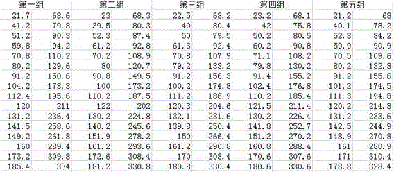
S20,将上一步骤测得的五组数据分别绘制折线图,其折线图如图8、9、10、11以及12所示。S20 , drawing the five groups of data measured in the previous step into a line graph respectively, and the line graph is shown in FIGS. 8 , 9 , 10 , 11 and 12 .
因此,根据测试数据可以看出压迫支架14端监测值与称重式传感器25端监测值具有良好的重复性,稳定性,一致性。Therefore, according to the test data, it can be seen that the monitoring value at the 14 end of the compression bracket and the monitoring value at the 25 end of the weighing sensor have good repeatability, stability and consistency.
请参照图1、图2所示,所述手动解锁装置包括第三齿轮42、与第三齿轮42啮合的第四齿轮43、与第四齿轮43同轴连接且设于第一同步带23上的第五带轮44以及用于驱动第三齿轮42转动的手轮45。Referring to FIG. 1 and FIG. 2 , the manual unlocking device includes a
当发生断电或意外时,转动手轮45,手轮45驱动第三齿轮42转动从而带动第四齿轮43转动,第四齿轮43带动第五带轮44转动,从而使得第一同步带23驱动压迫支架14上升,通过利用手动解锁装置来释放压迫力,避免对病人造成压迫伤害。当压迫支架14上升到一定高度后,也可以反向转动手轮45,从而实现手动施加压迫力的目的,操作十分简便,且安全可靠。When a power failure or accident occurs, turn the
具体而言,所述第三齿轮42、第四齿轮43、第五带轮44以及手轮45均设于压迫支架14上。所述手轮45具有一转轴451,所述阻尼器41设于手轮45的转轴451上。在电机32工作时,阻尼器41可限制手动解锁装置活动,此时第五带轮44不会发生转动,压迫支架14可上下活动;当转动手轮45时,手动解锁装置克服了阻尼器41的阻尼力,从而驱动第五带轮44转动,从而实现压迫支架14的上下活动。Specifically, the
本发明的工作原理如下所示:The working principle of the present invention is as follows:
当电机32正转时,第一同步带23向下活动,压迫支架14以设定的速度下降到临床要求的高度后,与压迫面板11共同将乳房压紧。电机32反转时,则第一同步带23向上活动,压迫支架14上升,离开压迫面板11。When the
当发生断电或意外时,转动手轮45,手轮45驱动第三齿轮42转动从而带动第四齿轮43转动,第四齿轮43带动第五带轮44转动,从而使得第一同步带23向上活动,压迫支架14也随着上升,通过利用手动解锁装置来释放压迫力,避免对病人造成压迫伤害。当压迫支架14上升到一定高度后,也可以反向转动手轮45,从而实现手动施加压迫力的目的,操作十分简便,且安全可靠。When a power failure or an accident occurs, turn the
在压迫支架14下降以及上升过程中,由于滑块座13与第二同步带54固定连接,因此压迫支架14会带动第二同步带54上下活动,从而使得第三带轮52转动,进而驱动电位器51转动,电位器51输出电信号,该信号用于检测压迫支架14的升降高度,从而精确控制压迫支架14的升降高度,且通过称重式传感器25可测得本发明压迫力的大小,从而可精确控制压迫力的大小,避免对病人造成压迫伤害。During the descending and ascending process of the
应当理解的是,本发明的应用不限于上述的举例,对本领域普通技术人员来说,可以根据上述说明加以改进或变换,所有这些改进和变换都应属于本发明所附权利要求的保护范围。It should be understood that the application of the present invention is not limited to the above examples. For those of ordinary skill in the art, improvements or transformations can be made according to the above descriptions, and all these improvements and transformations should belong to the protection scope of the appended claims of the present invention.
Claims (4)
Priority Applications (1)
| Application Number | Priority Date | Filing Date | Title |
|---|---|---|---|
| CN201510604669.6A CN105286904B (en) | 2015-09-21 | 2015-09-21 | A breast machine compression device |
Applications Claiming Priority (1)
| Application Number | Priority Date | Filing Date | Title |
|---|---|---|---|
| CN201510604669.6A CN105286904B (en) | 2015-09-21 | 2015-09-21 | A breast machine compression device |
Publications (2)
| Publication Number | Publication Date |
|---|---|
| CN105286904A CN105286904A (en) | 2016-02-03 |
| CN105286904B true CN105286904B (en) | 2020-06-23 |
Family
ID=55185227
Family Applications (1)
| Application Number | Title | Priority Date | Filing Date |
|---|---|---|---|
| CN201510604669.6A Expired - Fee Related CN105286904B (en) | 2015-09-21 | 2015-09-21 | A breast machine compression device |
Country Status (1)
| Country | Link |
|---|---|
| CN (1) | CN105286904B (en) |
Cited By (1)
| Publication number | Priority date | Publication date | Assignee | Title |
|---|---|---|---|---|
| US12544019B2 (en) | 2024-07-01 | 2026-02-10 | Hologic, Inc. | X-ray mammography and/or breast tomosynthesis using a compression paddle with an inflatable jacket enhancing imaging and improving patient comfort |
Families Citing this family (14)
| Publication number | Priority date | Publication date | Assignee | Title |
|---|---|---|---|---|
| US7869563B2 (en) | 2004-11-26 | 2011-01-11 | Hologic, Inc. | Integrated multi-mode mammography/tomosynthesis x-ray system and method |
| US11259759B2 (en) | 2011-11-18 | 2022-03-01 | Hologic Inc. | X-ray mammography and/or breast tomosynthesis using a compression paddle |
| CN106264578B (en) * | 2016-08-05 | 2019-08-30 | 深圳圣诺医疗设备股份有限公司 | Breast X-ray system and its compressorium |
| JP2019533510A (en) | 2016-11-08 | 2019-11-21 | ホロジック, インコーポレイテッドHologic, Inc. | Imaging using curved compression elements |
| CN107053139A (en) * | 2017-04-11 | 2017-08-18 | 沈阳翰和科技工程有限公司 | A kind of automatic braking type truss manipulator |
| WO2019033022A1 (en) | 2017-08-11 | 2019-02-14 | Hologic, Inc. | Breast compression paddle having an inflatable jacket |
| JP7229228B2 (en) | 2017-08-11 | 2023-02-27 | ホロジック, インコーポレイテッド | Breast compression paddle with access angle |
| EP4129188A1 (en) | 2017-08-16 | 2023-02-08 | Hologic, Inc. | Techniques for breast imaging patient motion artifact compensation |
| CN108209953A (en) * | 2018-01-17 | 2018-06-29 | 江苏美伦影像系统有限公司 | A kind of mammary gland X ray photographing system that can promptly discharge compressing |
| CN110123357A (en) * | 2019-05-31 | 2019-08-16 | 河南省肿瘤医院 | Breast molybdenum target inspection compressorium |
| KR20220130759A (en) | 2020-01-24 | 2022-09-27 | 홀로직, 인크. | Horizontal-Displaceable Foam Breast Compression Paddles |
| EP4329627A1 (en) | 2021-04-26 | 2024-03-06 | Hologic, Inc. | Systems and methods for measuring thickness of foam compressive elements |
| US11786191B2 (en) | 2021-05-17 | 2023-10-17 | Hologic, Inc. | Contrast-enhanced tomosynthesis with a copper filter |
| CN116661515B (en) * | 2023-05-30 | 2026-01-13 | 达影医疗(中山)有限公司 | Dynamic adjustment method for hand wheel damping, mammary machine, control device and storage medium |
Citations (4)
| Publication number | Priority date | Publication date | Assignee | Title |
|---|---|---|---|---|
| EP0630998A1 (en) * | 1993-06-21 | 1994-12-28 | Sanei-Kisetsu Co., Ltd. | Method and apparatus for manufacturing piled-up cotton mat |
| CN103321511A (en) * | 2013-07-16 | 2013-09-25 | 法中轨道交通运输设备(上海)有限公司 | Belt drive door operator locking and unlocking mechanism |
| CN103670249A (en) * | 2013-12-17 | 2014-03-26 | 浙江朗德实业有限公司 | Resistance-free rope winding device |
| CN204038418U (en) * | 2014-07-23 | 2014-12-24 | 深圳市万臣科技有限公司 | For the anti-slip module that cuts off self-lock in automation equipment |
Family Cites Families (5)
| Publication number | Priority date | Publication date | Assignee | Title |
|---|---|---|---|---|
| JP2012235961A (en) * | 2011-05-13 | 2012-12-06 | Fujifilm Corp | Radiation imaging apparatus |
| WO2014092210A1 (en) * | 2012-12-10 | 2014-06-19 | 주식회사 레이언스 | X-ray system |
| CN103126715B (en) * | 2013-03-05 | 2015-06-10 | 华润万东医疗装备股份有限公司 | Compression device of digital flat mammography |
| CN103876760A (en) * | 2013-11-29 | 2014-06-25 | 沈阳东软医疗系统有限公司 | Breast X-ray radiography system and pressing device |
| CN205019082U (en) * | 2015-09-21 | 2016-02-10 | 北京国药恒瑞美联信息技术有限公司 | Mammary gland machine oppression device |
-
2015
- 2015-09-21 CN CN201510604669.6A patent/CN105286904B/en not_active Expired - Fee Related
Patent Citations (4)
| Publication number | Priority date | Publication date | Assignee | Title |
|---|---|---|---|---|
| EP0630998A1 (en) * | 1993-06-21 | 1994-12-28 | Sanei-Kisetsu Co., Ltd. | Method and apparatus for manufacturing piled-up cotton mat |
| CN103321511A (en) * | 2013-07-16 | 2013-09-25 | 法中轨道交通运输设备(上海)有限公司 | Belt drive door operator locking and unlocking mechanism |
| CN103670249A (en) * | 2013-12-17 | 2014-03-26 | 浙江朗德实业有限公司 | Resistance-free rope winding device |
| CN204038418U (en) * | 2014-07-23 | 2014-12-24 | 深圳市万臣科技有限公司 | For the anti-slip module that cuts off self-lock in automation equipment |
Cited By (1)
| Publication number | Priority date | Publication date | Assignee | Title |
|---|---|---|---|---|
| US12544019B2 (en) | 2024-07-01 | 2026-02-10 | Hologic, Inc. | X-ray mammography and/or breast tomosynthesis using a compression paddle with an inflatable jacket enhancing imaging and improving patient comfort |
Also Published As
| Publication number | Publication date |
|---|---|
| CN105286904A (en) | 2016-02-03 |
Similar Documents
| Publication | Publication Date | Title |
|---|---|---|
| CN105286904B (en) | A breast machine compression device | |
| CN101243979A (en) | Diagnosis device and method for displacing a diagnosis unit of the diagnosis device | |
| CN106872292A (en) | A kind of portable geosynthetics comprehensive test instrument | |
| CN108692692B (en) | A seat frame height adjustment gap detection device | |
| CN204649401U (en) | C-arm X-ray machine sports fatigue pick-up unit | |
| CN111743561B (en) | X-ray filtering device | |
| CN220170190U (en) | A CCD-based cylindrical outer contour detection equipment | |
| CN221706384U (en) | High-precision cable meter counter | |
| CN107355660A (en) | X-ray machine suspension | |
| CN107468446A (en) | A kind of Novel nursing bed apparatus | |
| CN219201964U (en) | A clinical metal detection device for radiology department | |
| CN114486230B (en) | Torque detection device for automobile seat angle adjuster | |
| CN208621302U (en) | One kind being used for rubber key end product drawing force test device | |
| CN116269470A (en) | Traveling balance structure for CT detection flat bed | |
| CN202960539U (en) | Beam-defining clipper | |
| CN206608711U (en) | Mobile portable Formula X ray device for fast detecting | |
| CN212799531U (en) | Automatic lifting mechanism and screen detection equipment | |
| CN220602785U (en) | Subway shielding door toothed belt tension detection device | |
| CN114777627A (en) | Glass flatness check out test set | |
| CN114305394A (en) | A physical health detection platform and method based on artificial intelligence | |
| CN216205821U (en) | Detection mechanism of brake pad drilling machine | |
| CN111248863B (en) | A pressurized device that induces a hyperemic response in human skin | |
| CN221898914U (en) | A shear test device for photoelasticity instrument | |
| CN107063995A (en) | A kind of treadmill foot platform frictional testing machine | |
| CN208476449U (en) | A kind of torque tester of electricity loss brake |
Legal Events
| Date | Code | Title | Description |
|---|---|---|---|
| C06 | Publication | ||
| PB01 | Publication | ||
| CB02 | Change of applicant information |
Address after: 100176 Beijing branch of Daxing District economic and Technological Development Zone fourteen Street No. 99 Building 2 room B162 Applicant after: TCL MEDICAL RADIATION TECHNOLOGY (BEIJING) Co.,Ltd. Address before: 100176 Beijing branch of Daxing District economic and Technological Development Zone fourteen Street No. 99 Building 2 room B162 Applicant before: Beijing Sinopharm Hundric Medline Info. Tec. Co.,Ltd. |
|
| COR | Change of bibliographic data | ||
| SE01 | Entry into force of request for substantive examination | ||
| SE01 | Entry into force of request for substantive examination | ||
| TA01 | Transfer of patent application right |
Effective date of registration: 20181227 Address after: 214000 Building 108, Zone B, Science Park, University of Sensor Network, No. 20 Qingyuan Road, Wuxi New District, Wuxi City, Jiangsu Province Applicant after: TCL MEDICAL NUCLEAR MAGNETISM TECHNOLOGY (WUXI) CO.,LTD. Address before: Room B162, Building 99, Kechuang 14th Street, Daxing Economic and Technological Development Zone, Beijing, 100176 Applicant before: TCL MEDICAL RADIATION TECHNOLOGY (BEIJING) Co.,Ltd. |
|
| TA01 | Transfer of patent application right | ||
| TA01 | Transfer of patent application right | ||
| TA01 | Transfer of patent application right |
Effective date of registration: 20190430 Address after: Room 516-3, Building 58 Xiangke Road, Pudong New Area Free Trade Pilot Area, Shanghai 200000 Applicant after: Shanghai Huiying Medical Technology Co.,Ltd. Address before: 214000 Building 108, Zone B, Science Park, University of Sensor Network, No. 20 Qingyuan Road, Wuxi New District, Wuxi City, Jiangsu Province Applicant before: TCL MEDICAL NUCLEAR MAGNETISM TECHNOLOGY (WUXI) CO.,LTD. |
|
| GR01 | Patent grant | ||
| GR01 | Patent grant | ||
| CF01 | Termination of patent right due to non-payment of annual fee | ||
| CF01 | Termination of patent right due to non-payment of annual fee |
Granted publication date: 20200623 |