CN1051606C - Valve device - Google Patents
Valve device Download PDFInfo
- Publication number
- CN1051606C CN1051606C CN95190421A CN95190421A CN1051606C CN 1051606 C CN1051606 C CN 1051606C CN 95190421 A CN95190421 A CN 95190421A CN 95190421 A CN95190421 A CN 95190421A CN 1051606 C CN1051606 C CN 1051606C
- Authority
- CN
- China
- Prior art keywords
- valve
- valve body
- valve seat
- resin
- water
- Prior art date
- Legal status (The legal status is an assumption and is not a legal conclusion. Google has not performed a legal analysis and makes no representation as to the accuracy of the status listed.)
- Expired - Lifetime
Links
Images


Classifications
-
- F—MECHANICAL ENGINEERING; LIGHTING; HEATING; WEAPONS; BLASTING
- F16—ENGINEERING ELEMENTS AND UNITS; GENERAL MEASURES FOR PRODUCING AND MAINTAINING EFFECTIVE FUNCTIONING OF MACHINES OR INSTALLATIONS; THERMAL INSULATION IN GENERAL
- F16K—VALVES; TAPS; COCKS; ACTUATING-FLOATS; DEVICES FOR VENTING OR AERATING
- F16K25/00—Details relating to contact between valve members and seats
- F16K25/005—Particular materials for seats or closure elements
-
- C—CHEMISTRY; METALLURGY
- C08—ORGANIC MACROMOLECULAR COMPOUNDS; THEIR PREPARATION OR CHEMICAL WORKING-UP; COMPOSITIONS BASED THEREON
- C08L—COMPOSITIONS OF MACROMOLECULAR COMPOUNDS
- C08L71/00—Compositions of polyethers obtained by reactions forming an ether link in the main chain; Compositions of derivatives of such polymers
-
- F—MECHANICAL ENGINEERING; LIGHTING; HEATING; WEAPONS; BLASTING
- F16—ENGINEERING ELEMENTS AND UNITS; GENERAL MEASURES FOR PRODUCING AND MAINTAINING EFFECTIVE FUNCTIONING OF MACHINES OR INSTALLATIONS; THERMAL INSULATION IN GENERAL
- F16K—VALVES; TAPS; COCKS; ACTUATING-FLOATS; DEVICES FOR VENTING OR AERATING
- F16K11/00—Multiple-way valves, e.g. mixing valves; Pipe fittings incorporating such valves
- F16K11/02—Multiple-way valves, e.g. mixing valves; Pipe fittings incorporating such valves with all movable sealing faces moving as one unit
- F16K11/06—Multiple-way valves, e.g. mixing valves; Pipe fittings incorporating such valves with all movable sealing faces moving as one unit comprising only sliding valves, i.e. sliding closure elements
- F16K11/078—Multiple-way valves, e.g. mixing valves; Pipe fittings incorporating such valves with all movable sealing faces moving as one unit comprising only sliding valves, i.e. sliding closure elements with pivoted and linearly movable closure members
- F16K11/0782—Single-lever operated mixing valves with closure members having flat sealing faces
-
- Y—GENERAL TAGGING OF NEW TECHNOLOGICAL DEVELOPMENTS; GENERAL TAGGING OF CROSS-SECTIONAL TECHNOLOGIES SPANNING OVER SEVERAL SECTIONS OF THE IPC; TECHNICAL SUBJECTS COVERED BY FORMER USPC CROSS-REFERENCE ART COLLECTIONS [XRACs] AND DIGESTS
- Y10—TECHNICAL SUBJECTS COVERED BY FORMER USPC
- Y10T—TECHNICAL SUBJECTS COVERED BY FORMER US CLASSIFICATION
- Y10T137/00—Fluid handling
- Y10T137/8593—Systems
- Y10T137/86493—Multi-way valve unit
- Y10T137/86549—Selective reciprocation or rotation
-
- Y—GENERAL TAGGING OF NEW TECHNOLOGICAL DEVELOPMENTS; GENERAL TAGGING OF CROSS-SECTIONAL TECHNOLOGIES SPANNING OVER SEVERAL SECTIONS OF THE IPC; TECHNICAL SUBJECTS COVERED BY FORMER USPC CROSS-REFERENCE ART COLLECTIONS [XRACs] AND DIGESTS
- Y10—TECHNICAL SUBJECTS COVERED BY FORMER USPC
- Y10T—TECHNICAL SUBJECTS COVERED BY FORMER US CLASSIFICATION
- Y10T137/00—Fluid handling
- Y10T137/8593—Systems
- Y10T137/86493—Multi-way valve unit
- Y10T137/86815—Multiple inlet with single outlet
Landscapes
- Engineering & Computer Science (AREA)
- General Engineering & Computer Science (AREA)
- Mechanical Engineering (AREA)
- Chemical & Material Sciences (AREA)
- Health & Medical Sciences (AREA)
- Chemical Kinetics & Catalysis (AREA)
- Medicinal Chemistry (AREA)
- Polymers & Plastics (AREA)
- Organic Chemistry (AREA)
- Multiple-Way Valves (AREA)
- Sliding Valves (AREA)
Abstract
Description
技术领域technical field
本发明是关于自来水水龙头、冷/热水混合用阀栓、便器用温水冲洗器的流路转换阀等中使用的、阀体与阀座滑动接触的滑动型阀装置。The present invention relates to a sliding type valve device in which a valve body and a valve seat are in sliding contact for use in tap water faucets, valve plugs for mixing hot and cold water, flow path switching valves for warm water flushers for toilets, and the like.
背景技术Background technique
已知的用于将冷/热水混合的滑动型阀装置如图9所示。A known sliding type valve device for mixing cold/hot water is shown in FIG. 9 .
该阀装置的结构是:在阀壳40的下部安装有底板41,在底板41上安装有两个环型填密圈42(图中略去其中的一个),以各环型填密圈42的内侧作为流入口43,在底板41上设置阀座44,阀座44上设置分别与上述各流入口43连通的两个阀孔45(图中略去一个),在与上述阀座44的上表面接触的阀体46的上面安装有可以自由转动的手柄保持器47,通过销子48而可以自由滑动地支承在手柄保持器47上的手柄轴49的下端与阀体46连接,通过操作上述手柄轴49,使之上下、左右摇动,可以使阀体46沿阀座44的上表面滑动,打开或关闭两个阀孔45。The structure of this valve device is: a
当两个阀孔45开路时,由一个流入口43供入的热水和由另一个流入口43供入的凉水经阀孔45流入在阀体46上形成的流路50,然后进入混合室51,在该混合室51中混合,由阀壳40上形成的出口52流出。When the two
另外,在上述阀装置中,手柄保持器47的下面安装有环形的密封部件53,该密封部件53与阀体46的上表面接触,防止水从阀体46与手柄保持器47之间通过手柄保持器47上的轴插入孔54泄漏到外面,另外,在手柄保持器47与阀壳40之间安装有环型密封部件55,用以防止水从47和40两个部件之间漏出。In addition, in the above-mentioned valve device, an
特开昭63-36765中公布了一种这样的阀装置(参见图9),其阀体46和阀座44中有一方用陶瓷制成,另一方用含氟树脂、超高分子聚乙烯等具有自润滑性的树脂或填充了二硫化钼、碳等润滑性较高的填料的树脂制成,使阀体46的滑动性得到提高。A kind of such valve device (referring to Fig. 9) has been announced in JP-A-63-36765, wherein one side is made of ceramics in its
以往的这种由具有自润滑性的合成树脂制成的阀体,抗蠕变性较差,另外,即使用纤维增强材料增强,由于树脂与增强材料的润湿性较差,不能获得充分的增强效果,因而只能在较低的水压下防止漏水。The conventional valve body made of self-lubricating synthetic resin has poor creep resistance. In addition, even if it is reinforced with fiber reinforced materials, sufficient wettability cannot be obtained due to poor wettability between the resin and the reinforced material. Enhanced effect, thus preventing water leaks only at low water pressures.
另外,采用自润滑性树脂以外的增强效果较大的树脂,通过填充具有自润滑性的填料而获得阀体需要的润滑性时,需要添加大量的润滑性填料,导致冲击强度和抗蠕变性显著降低,产生龟裂或止水不良等问题。In addition, when using a resin with a greater reinforcing effect than self-lubricating resins, when filling self-lubricating fillers to obtain the lubricity required by the valve body, it is necessary to add a large amount of lubricating fillers, resulting in impact strength and creep resistance. Significantly reduced, resulting in problems such as cracks or poor water sealing.
特开平2-190677中公布了一种抗蠕变性和润滑性均有某种程度改善的树脂组合物,它是由25-80%(重量)的聚苯硫醚树脂(以下简称PPS树脂)和20-75%(重量)的平均纤维直径在8μm以下的碳纤维构成,并配加了天然云母等无机粉末填充剂。JP-2-190677 discloses a resin composition with improved creep resistance and lubricity to some extent, which is composed of 25-80% (by weight) polyphenylene sulfide resin (hereinafter referred to as PPS resin) And 20-75% (weight) of carbon fibers with an average fiber diameter below 8 μm, and added inorganic powder fillers such as natural mica.
另外,特开平6-213341中公布了一种提高以PPS树脂为主要成分的阀元件彼此间滑动接触面的耐磨性、防止因滑动接触面上产生划伤而导致止水性能降低的技术,其中,阀座与阀体至少有一方是由在聚氰基芳基醚树脂中配入碳纤维而形成的树脂组合物的成形体构成。In addition, JP-A-6-213341 discloses a technique for improving the wear resistance of the sliding contact surfaces between valve elements mainly composed of PPS resin and preventing the deterioration of the water-stopping performance due to scratches on the sliding contact surfaces. Wherein, at least one of the valve seat and the valve body is composed of a molded body of a resin composition formed by blending carbon fibers into polycyanoaryl ether resin.
另外,本发明人在特开平3-265769中公布了一种阀装置,其中,阀体是在PPS树脂或在含该树脂的聚合物合金中含有填充剂的合成树脂组合物制成的,另外,手柄保持器下面的密封部件由高分子量聚乙烯(HMWPE)制成,从而在阀体与阀座之间以及阀体与上述密封部件之间产生良好的滑动性能。In addition, the present inventors disclosed a valve device in JP-A-3-265769, wherein the valve body is made of a synthetic resin composition containing a filler in a PPS resin or a polymer alloy containing the resin, and in addition , The sealing part under the handle holder is made of high molecular weight polyethylene (HMWPE), so as to produce good sliding performance between the valve body and the valve seat and between the valve body and the above-mentioned sealing part.
但是,采用配入碳纤维的阀体的现有技术阀装置成形时的收缩率具有各向异性,尺寸精度差,自润滑性也不好,存在一系列问题。However, the shrinkage rate of the prior art valve device using a valve body fitted with carbon fiber has anisotropy, poor dimensional accuracy, and poor self-lubricating property, and there are a series of problems.
另外,对于阀装置来说,除了阀体和阀座的尺寸精度及自润滑性外,还需要具有下列性能,即耐磨性或有异物进入时表面粗糙度不增大的性能、膨胀性、蠕变性、有机械冲击或热冲击时平面度不改变的性能、即止水性不降低的性能。In addition, for the valve device, in addition to the dimensional accuracy and self-lubricating properties of the valve body and seat, the following properties are required, namely, wear resistance or performance that does not increase the surface roughness when foreign matter enters, expandability, Creep property, the performance that the flatness does not change when there is mechanical shock or thermal shock, that is, the performance that the water-stopping property does not decrease.
本发明的第一个任务是解决上述问题,提供一种阀装置,该阀装置在使用过程中即使阀体与阀座的滑动接触面的表面粗糙度增大或有异物侵入滑动接触面也不易产生划伤,长时间连续使用时具有可靠的止水性,并且调节水量时手柄的操作性良好。The first task of the present invention is to solve the above problems, and to provide a valve device that is not easily damaged even if the surface roughness of the sliding contact surface between the valve body and the valve seat increases or foreign matter invades the sliding contact surface during use. Scratches are generated, and it has reliable water stop performance when used continuously for a long time, and the operability of the handle when adjusting the amount of water is good.
可是,当阀装置的阀座用合成树脂制成、阀体用陶瓷制成时,止水时发生漏水并且手柄的操作也不轻便。However, when the valve seat of the valve unit is made of synthetic resin and the valve body is made of ceramics, water leakage occurs when the water is stopped and the handle is not easy to operate.
产生这些问题的原因据认为是由于作用在上述图9中所示的环形填密圈42上的给水压使该环形填密圈42向上压阀座44的外周部,使阀座44的外周部向上方变形,阀座44与阀体46的接触部位产生间隙的缘故。The reason for these problems is considered to be that the
本发明的第二个任务是提供一种阀装置,与上述第一个任务同样,使阀体滑动时的手柄操作性可以长期保持良好,同时,在阀体由陶瓷材料制成的情况下可以防止止水时的漏水。The second object of the present invention is to provide a valve device which, like the above-mentioned first object, can maintain good handle operability for a long period of time when the valve body slides, and at the same time, when the valve body is made of a ceramic material, it can Prevent water leakage at the time of water stop.
另外,以往的阀装置借助于由橡胶类弹性材料构成的密封部件的弹力将用合成树脂或陶瓷制成的阀体压向阀座一侧而处于密封状态,但是,由于与阀体滑动接触的环形密封部件的滑动阻力很大,手柄的操作性不好,即使使用润滑油也不能完全得到改善。In addition, the conventional valve device is in a sealed state by pressing the valve body made of synthetic resin or ceramics to the valve seat side by means of the elastic force of the sealing member made of rubber elastic material. However, due to the sliding contact with the valve body The sliding resistance of the annular seal member is large, and the operability of the handle is not good, and even if lubricating oil is used, it cannot be completely improved.
在这种情况下,也可以考虑代替密封部件使滑动性良好的合成树脂制的环形阀座滑动接触,将该阀座压紧在阀体上,在滑动接触面以外的适当位置上配置弹性橡胶。In this case, instead of the sealing member, it is also conceivable to make a synthetic resin annular valve seat with good sliding properties to slide, press the valve seat to the valve body, and arrange elastic rubber at an appropriate position other than the sliding contact surface. .
但这样一来,由于阀座与阀体的水密性不充分,当环形阀座承受流体压力时,容易从阀座与阀体的滑动接触面漏水。However, since the watertightness between the valve seat and the valve body is insufficient, when the annular valve seat is subjected to fluid pressure, it is easy to leak water from the sliding contact surface between the valve seat and the valve body.
本发明的第三个任务是解决上述问题,不妨碍阀装置的操作性,防止从没有阀孔、与流入路相反一侧设置的环形阀座与阀体的滑动接触面漏水的现象。The third object of the present invention is to solve the above problems without hindering the operability of the valve device and prevent water leakage from the sliding contact surface between the annular valve seat and the valve body provided on the side opposite to the inflow path without the valve hole.
发明的说明Description of the invention
为了解决上述第一个任务,本发明采用下面所述的结构,即在将阀体叠合在带有阀孔的阀座上、通过操作手柄使阀体相对于阀座滑动而打开或关闭上述阀孔的阀装置中,上述阀座和阀体至少有一方由每100份(重量)聚氰基芳基醚树脂配加40-165份(重量)平均粒径在25μm以下的玻璃状碳而形成的树脂组合物的成形体构成。In order to solve the above-mentioned first task, the present invention adopts the following structure, that is, after the valve body is stacked on the valve seat with the valve hole, the valve body is opened or closed by operating the handle to slide the valve body relative to the valve seat. In the valve device of the valve hole, at least one of the above-mentioned valve seat and the valve body is formed by adding 40-165 parts (weight) of glassy carbon with an average particle diameter of 25 μm or less per 100 parts (weight) of polycyanoaryl ether resin. The molded body of the formed resin composition constitutes.
上述树脂组合物还可以采用进一步配加30份(重量)以下的含氟树脂粉末、特别是四氟乙烯树脂粉末的树脂组合物。上述四氟乙烯树脂粉末也可以是再生四氟乙烯树脂粉末。The above-mentioned resin composition can also be a resin composition in which 30 parts (by weight) or less of fluorine-containing resin powder, especially tetrafluoroethylene resin powder is added. The above-mentioned tetrafluoroethylene resin powder may be regenerated tetrafluoroethylene resin powder.
另外,在本发明中,为了同时解决上述第一个任务和第二个任务,在带有阀孔的阀座由合成树脂制成、与该阀座叠合的阀体由陶瓷材料制成、通过操作手柄使阀体相对于阀座滑动而打开或关闭上述阀孔的阀装置中,在上述阀座的与阀体相对的一面的中央部位形成与阀体滑动接触的圆形突出部,该突出部的直径小于阀体的外径。In addition, in the present invention, in order to simultaneously solve the above-mentioned first and second tasks, the valve seat with the valve hole is made of synthetic resin, the valve body superimposed on the valve seat is made of ceramic material, In the valve device in which the valve body is slid relative to the valve seat by operating the handle to open or close the above-mentioned valve hole, a circular protrusion in sliding contact with the valve body is formed at the center of the surface of the valve seat opposite to the valve body. The diameter of the protrusion is smaller than the outer diameter of the valve body.
另外,在带有阀孔的阀座由合成树脂制成、将阀体叠合设置在该阀座上、同时设置与该阀体滑动接触的密封部件、将阀体在阀体壳内水密密封、在该状态下通过操作手柄使上述阀体相对于阀座滑动而打开或关闭上述阀孔的阀装置中,在上述阀座的与阀体相对的一面的中央部位形成与阀体滑动接触的圆形突出部,该突出部的直径小于阀体的外径,上述阀体的与阀座相对的滑动接触面由陶瓷材料制成,上述阀体的与上述密封部件相对的滑动接触面由合成树脂制成。In addition, the valve seat with the valve hole is made of synthetic resin, the valve body is stacked on the valve seat, and the sealing member is provided in sliding contact with the valve body, so that the valve body is watertightly sealed in the valve body shell. In this state, in the valve device in which the above-mentioned valve body is slid relative to the valve seat by operating the handle to open or close the above-mentioned valve hole, a center portion of the surface of the above-mentioned valve seat opposite to the valve body is formed to be in sliding contact with the valve body. A circular protrusion, the diameter of which is smaller than the outer diameter of the valve body, the sliding contact surface of the valve body opposite to the valve seat is made of ceramic material, and the sliding contact surface of the valve body opposite to the sealing member is made of synthetic Made of resin.
为了减小阀体的滑动阻力,进一步减轻手柄的操作力,可以在突出部的阀体滑动面上预先形成孔。In order to reduce the sliding resistance of the valve body and further reduce the operating force of the handle, holes can be pre-formed on the valve body sliding surface of the protrusion.
在本发明中,为了同时解决上述第一个任务和上述第三个任务,在带有阀孔的阀座上叠合阀体、通过操作手柄使阀体相对于阀座滑动而打开或关闭上述阀孔的阀装置中,在支承手柄、使阀体与阀座紧密接触的手柄保持器的与阀体的滑动接触面上形成若干个同心圆状的沟槽。In the present invention, in order to solve the above-mentioned first task and the above-mentioned third task at the same time, the valve body is stacked on the valve seat with a valve hole, and the valve body is opened or closed by operating the handle to make the valve body slide relative to the valve seat. In the valve device of the valve hole, several concentric circular grooves are formed on the sliding contact surface of the handle holder which supports the handle and makes the valve body and the valve seat closely contact with the valve body.
优选的是使上述阀装置的上述手柄保持器的与阀体的滑动接触面形成内周缘比外周缘隆起的中间高的形状,最好是在上述沟槽中保持有润滑油或润滑脂。Preferably, the sliding contact surface of the handle holder of the valve device and the valve body is formed in a shape in which the inner periphery is raised higher than the outer periphery, and lubricating oil or grease is preferably held in the groove.
附图的简要说明 Brief description of the drawings
图1是实施例9的纵剖面正视图。Fig. 1 is a longitudinal sectional front view of
图2是沿图1的II-II线的剖面图。Fig. 2 is a sectional view along line II-II of Fig. 1 .
图3是实施例9的部件分解立体图。Fig. 3 is an exploded perspective view of the ninth embodiment.
图4是实施例10的纵剖面正视图。Fig. 4 is a longitudinal sectional front view of the tenth embodiment.
图5是实施例10的部件分解立体图。Fig. 5 is an exploded perspective view of the tenth embodiment.
图6是冷/热水混合阀栓的外观和手柄操作状态的立体示意图。Fig. 6 is a three-dimensional schematic diagram of the appearance of the cold/hot water mixing valve plug and the operating state of the handle.
图7是实施例12的纵剖面正视图。Fig. 7 is a longitudinal sectional front view of the twelfth embodiment.
图8是实施例12的阀座的底面图。Fig. 8 is a bottom view of the valve seat of the twelfth embodiment.
图9是现有技术阀装置的纵剖面正视图。Fig. 9 is a longitudinal sectional front view of a prior art valve device.
实施本发明的最佳方式Best Mode for Carrying Out the Invention
下面详细加以说明。Describe in detail below.
首先,本发明中的聚氰基芳基醚树脂(以下简称PEN)是由下列式1表示的重复单元构成的化合物,或者是除了该重复单元外、在不丧失PEN原有特性的范围内同时共存有约20%(摩尔)以下的由下列式2表示的另一重复单元的聚合物。式1
这样的PEN例如最好是以对氯酚为溶剂的0.2g/dl浓度的溶液在60℃下的比浓粘度(ηsp/C)为0.3dl/g以上者,例如出光兴产社制造的聚醚腈(ID300)。特开昭63-3059的实施例中公布了PEN的制造方法。Such PEN, for example, preferably has a reduced viscosity (ηsp/C) of 0.3 dl/g or more of a solution of 0.2 g/dl concentration of p-chlorophenol as a solvent at 60° C. Ether nitrile (ID300). The manufacturing method of PEN is disclosed in the Example of Unexamined-Japanese-Patent No. 63-3059.
本发明中使用的玻璃状碳是将热固性合成树脂酚醛树脂或呋喃树脂等碳化烧成而得到的没有特定晶体结构的玻璃状(无定形)的碳,通常使用粉末状物。The glassy carbon used in the present invention is a glassy (amorphous) carbon without a specific crystal structure obtained by carbonizing and firing a thermosetting synthetic resin such as a phenolic resin or a furan resin, and is usually used in powder form.
以酚醛树脂粉末为原料的玻璃状碳的市售品有将分子内具有羟甲基、重均分子量在3000以上的酚醛树脂在800℃或2000℃烧成(热处理)而得到的产物(钟纺社制造:BELL-PEARL C-800、BELL-PEARL C-2000),可以使用将其调整成平均粒径在25μm以下的微粒状物。玻璃状碳的热处理温度越高,所得到的结构越接近于石墨。The commercially available glassy carbon made of phenolic resin powder is a product obtained by firing (heat treatment) a phenolic resin with a methylol group in the molecule and a weight-average molecular weight of more than 3000 at 800°C or 2000°C (Zhong spinning Manufactured by: BELL-PEARL C-800, BELL-PEARL C-2000), fine particles adjusted to an average particle size of 25 μm or less can be used. The higher the heat treatment temperature of glassy carbon, the closer the resulting structure is to graphite.
在本发明中,构成阀装置的树脂阀体的原料配比是每100份(重量)PEN配加40-165份(重量)的玻璃状碳,这是因为玻璃状碳低于上述规定范围时,弹性模量过小,阀体不能充分止水,反之,超过上述规定范围时,成形性很差并且抗冲击强度显著降低。In the present invention, the raw material ratio of the resin valve body constituting the valve device is to add 40-165 parts (weight) of glassy carbon per 100 parts (weight) of PEN. , the modulus of elasticity is too small, the valve body can not fully stop water, on the contrary, when it exceeds the above specified range, the formability is poor and the impact strength is significantly reduced.
另外,每100份(重量)的PEN配加40-165份(重量)的玻璃状碳外还可以再添加含氟树脂粉末。这是因为添加含氟树脂粉末可以改善滑动性,减小阀装置的手柄转矩,同时还可以消除操作手柄时容易产生的滑动音(嗓音)。In addition, besides adding 40-165 parts (weight) of glassy carbon per 100 parts (weight) of PEN, fluorine-containing resin powder can also be added. This is because the addition of fluorine-containing resin powder can improve sliding properties, reduce the handle torque of the valve device, and can also eliminate the sliding sound (sound) that tends to occur when operating the handle.
上述含氟树脂的有代表性的例子可以举出下列树脂,〔 〕内的数字表示热分解温度。Representative examples of the above-mentioned fluorine-containing resins include the following resins, and the numbers in [ ] indicate thermal decomposition temperatures.
①聚四氟乙烯(PTFE),〔约508-538℃〕① Polytetrafluoroethylene (PTFE), [about 508-538°C]
②四氟乙烯-全氟烷基乙烯基醚共聚物(PFA),〔约464℃以上②Tetrafluoroethylene-perfluoroalkyl vinyl ether copolymer (PFA), [about 464°C or higher
③四氟乙烯-六氟丙烯共聚物(FEP),〔约419℃以上〕③Tetrafluoroethylene-hexafluoropropylene copolymer (FEP), [above about 419°C]
④聚三氟氯乙烯(PCTFE),〔约347-418℃〕④ Polychlorotrifluoroethylene (PCTFE), [about 347-418°C]
⑤四氟乙烯-乙烯共聚物(ETFE),〔约347℃以上〕⑤Tetrafluoroethylene-ethylene copolymer (ETFE), [above about 347°C]
⑥三氟氯乙烯-乙烯共聚物(FCTFE),〔约330℃以上〕⑥ Chlorotrifluoroethylene-ethylene copolymer (FCTFE), [above about 330°C]
⑦聚偏二氟乙烯(PVDF),〔约400-475℃〕⑦ Polyvinylidene fluoride (PVDF), [about 400-475°C]
⑧聚氟乙烯(PVF),〔约372-480℃〕⑧ Polyvinyl fluoride (PVF), [about 372-480°C]
⑨四氟乙烯-六氟丙烯-全氟烷基乙烯基醚共聚物(EPE)。⑨ Tetrafluoroethylene-hexafluoropropylene-perfluoroalkyl vinyl ether copolymer (EPE).
另外,含氟树脂也可以是两种以上上述含氟树脂的单体例如以大约1∶10至10∶1的聚合比率形成的共聚物或三元共聚物等的氟化聚烯烃等,它们具有固体润滑剂的特性。其中,PTFE具有良好的耐热性、耐化学药品性、非粘着性和低摩擦系数等,因而是特别优选的。In addition, the fluorine-containing resin may also be fluorinated polyolefins such as copolymers or terpolymers formed of monomers of two or more of the above-mentioned fluorine-containing resins at a polymerization ratio of about 1:10 to 10:1, etc., which have Properties of solid lubricants. Among them, PTFE is particularly preferable because of its excellent heat resistance, chemical resistance, non-adhesion, low coefficient of friction, and the like.
这些含氟树脂的微分热分解开始温度比较高,这很合乎要求。例如,PTFE和PVDF的分解点分别是约490℃和约350℃,它们的微分热分解开始温度分别是约555℃和约460℃。在含氟树脂中,全氟类的PTFE、PFA、FEP等因其良好的高温特性而被优先选用。因此,在熔融制造由聚氰基芳基醚树脂构成的阀体时,能较好地耐受上述的多次加热过程。特别是PTFE的分解点比聚氰基芳基醚树脂的熔点(340℃左右)还高约100℃,因而被优先选用。通过添加3-30份(重量)、尤其是5-15份(重量)的上述含氟树脂,可以获得良好的机械性能、标准品的抗压强度约为2100kgf/cm2的良好抗蠕变性及良好的绝热性、耐热水性等聚氰基芳基醚树脂的特性,此外还能提高抗冲击性、抗疲劳性、耐磨性等。These fluorine-containing resins have a relatively high differential thermal decomposition initiation temperature, which is desirable. For example, the decomposition points of PTFE and PVDF are about 490°C and about 350°C, respectively, and their differential thermal decomposition initiation temperatures are about 555°C and about 460°C, respectively. Among fluorine-containing resins, perfluorinated PTFE, PFA, FEP, etc. are preferred because of their good high-temperature characteristics. Therefore, when the valve body made of polycyanoaryl ether resin is melt-fabricated, it can better withstand the above-mentioned multiple heating processes. In particular, the decomposition point of PTFE is about 100°C higher than the melting point of polycyanoaryl ether resin (about 340°C), so it is preferred. By adding 3-30 parts (weight), especially 5-15 parts (weight) of the above-mentioned fluorine-containing resin, good mechanical properties can be obtained, and the compressive strength of the standard product is about 2100kgf/cm 2 Good creep resistance And good heat insulation, hot water resistance and other properties of polycyanoaryl ether resin, in addition to improving impact resistance, fatigue resistance, wear resistance and so on.
添加量低于3份(重量)时,不能得到预期的效果,超过30份(重量)时,由于其熔融粘度等,在后续的造粒或注塑成形时,熔融成形机等的机筒承受很大负荷,不能获得稳定的造粒性、注塑成形性和尺寸精度。When the addition amount is less than 3 parts (by weight), the expected effect cannot be obtained. When it exceeds 30 parts (by weight), due to its melt viscosity, etc., the barrel of the melt molding machine and the like will bear a lot of pressure during subsequent granulation or injection molding. With a large load, stable granulation properties, injection moldability, and dimensional accuracy cannot be obtained.
顺便提一下,PFA和FEP在约380℃下的熔融粘度分别是约104-105泊和约4×10⁴-103泊,特别是PTFE在约340-380℃下的熔融粘度是约1011-1012泊,这些含氟树脂在这样高的温度下仍具有约104-1012泊的高粘度特性,因而耐热性极好。Incidentally, the melt viscosities of PFA and FEP at about 380°C are about 10 4 -10 5 poise and about 4×10 4 -10 3 poise, respectively, and in particular, the melt viscosity of PTFE at about 340-380°C is about 10 11 -10 12 poise, these fluorine-containing resins have high viscosity characteristics of about 10 4 -10 12 poise at such a high temperature, and thus are excellent in heat resistance.
在配加PTFE时,也是每100份(重量)PEN配加30份(重量)以下的PTFE,因为配加量超过30份(重量)时,将显著损害PEN的机械性能,阀座或阀体上容易产生划伤。When adding PTFE, it is also per 100 parts (weight) of PEN to add less than 30 parts (weight) of PTFE, because when the amount exceeds 30 parts (weight), it will significantly damage the mechanical properties of PEN, the valve seat or the valve body. prone to scratches.
所使用的PTFE粉末的形状和大小没有特别的限制,在粒状的情况下,其粒径在70μm以下时可使树脂组成均一,因而是优选的。The shape and size of the PTFE powder to be used are not particularly limited, but in the case of granular, the particle size is preferably 70 μm or less because the resin composition can be made uniform.
另外,用再生PTFE粉末代替PTFE新料粉末时,不易影响PEN的机械性能。所谓再生PTFE粉末,是新料一次烧成后、粉碎而得到的粉末,这种粉末难以形成纤维状,可使配合得到的树脂组合物保持良好的熔融粘度,因而是改善成形性的良好添加剂。In addition, when the recycled PTFE powder is used to replace the virgin PTFE powder, it is not easy to affect the mechanical properties of PEN. The so-called regenerated PTFE powder is the powder obtained after the primary firing of the new material and pulverization. This powder is difficult to form a fibrous shape and can maintain a good melt viscosity of the resin composition obtained by blending. Therefore, it is a good additive to improve formability.
聚氰基芳基醚树脂是玻璃化转变温度为145℃左右的结晶性树脂,在阀体成形后通过进行热处理还可以促进结晶化,提高尺寸稳定性。Polycyanoaryl ether resin is a crystalline resin with a glass transition temperature of about 145°C. After the valve body is formed, heat treatment can also promote crystallization and improve dimensional stability.
如上所述,在耐热性良好的聚氰基芳基醚树脂中混以上述具有耐热性的填充剂后成形而得到的阀体,即使暴露于约100℃的热水中也不会发生热变形,具有足够的耐久性。As mentioned above, the valve body obtained by mixing the above-mentioned heat-resistant filler in the polycyanoarylether resin with good heat resistance and then molded will not break down even if it is exposed to hot water at about 100°C. Thermal deformation, with sufficient durability.
阀装置的阀体或阀座是将上述PEN和玻璃状碳以及PTFE粉末混合在一起,然后成形,混合的方法没有特别的限制。例如,可以使用汉歇尔混合机、球磨机、转鼓式混合机等将上述各原料、必要时还有各种添加剂逐个地或两种以上同时地进行干式混合。The valve body or the valve seat of the valve device is formed by mixing the above-mentioned PEN, glassy carbon, and PTFE powder, and the mixing method is not particularly limited. For example, each of the aforementioned raw materials and, if necessary, various additives can be dry-mixed one by one or two or more simultaneously using a Henschel mixer, a ball mill, a drum mixer, or the like.
然后,用加热辊、捏合机、班伯里密炼机、熔融挤出机等进行熔融混合,熔融加工成规定的形状。熔融混合的温度在PEN树脂熔化的温度以上,具体地说是330-400℃,优选340-380℃。Then, it is melt-mixed with a heating roll, a kneader, a Banbury mixer, a melt extruder, etc., and melt-processed into a predetermined shape. The temperature of melt mixing is above the melting temperature of the PEN resin, specifically 330-400°C, preferably 340-380°C.
熔融成形的方法也没有特别的限制,考虑到大批量生产和降低生产成本,最好是采用注塑成形法。另外,仅采用注塑成形法难以得到具有要求的滑动接触面平面度的最终形状,因此,采用注塑成形后立即在同一金属模内进行压缩成形的所谓注塑压缩成形法较为有利。There is no particular limitation on the method of melt forming, but it is preferable to use injection molding in consideration of mass production and lower production cost. In addition, it is difficult to obtain the final shape with the required flatness of the sliding contact surface only by injection molding. Therefore, it is advantageous to use the so-called injection compression molding in which compression molding is performed in the same mold immediately after injection molding.
成形后,为了获得滑动表面的良好平面度,最好是进行后加工,例如用平面磨床等修整成形品的平行度和平面度,然后用研磨机精磨去掉10-50μm的表层。此时,研磨用的磨料可以使用以氧化铝、碳化硅等为主要成分的磨料,其粒度应非常细小。After forming, in order to obtain a good flatness of the sliding surface, it is best to perform post-processing, such as using a surface grinder to trim the parallelism and flatness of the formed product, and then use a grinder to finely grind to remove the 10-50μm surface layer. At this time, the abrasive used for grinding can be an abrasive mainly composed of alumina, silicon carbide, etc., and its particle size should be very fine.
另外,用硬质的磨料研磨比金属软的树脂时,可能担心磨粒会陷入树脂中,使用#2000以下的磨料,磨粒基本上不会陷入树脂中,可以得到良好的平面度和表面粗糙度。其原因尚不清楚,据推测是由于使用硬质的磨粒时被研磨材料发出的热量较少,因而表面硬度和屈服应力等下降较小。In addition, when using hard abrasives to grind a resin softer than metal, you may worry that the abrasive grains will be trapped in the resin. Use abrasives below #2000, basically the abrasive grains will not be trapped in the resin, and you can get good flatness and surface roughness Spend. The reason for this is not clear, but it is presumed that the decrease in surface hardness and yield stress is small due to the fact that the material to be ground emits less heat when hard abrasive grains are used.
总之,在进行上述平面研磨的同时也完成了平面度的精加工。磨削和研磨所使用的装置可以容易地一次处理多个工件,另外,与陶瓷、金属等材料相比,树脂材料的加工时间要短得多,因而可以降低制造成本。In short, the finishing of the flatness is also completed while the above-mentioned flat grinding is carried out. The equipment used for grinding and lapping can easily process multiple workpieces at a time, and the processing time of resin materials is much shorter compared with materials such as ceramics and metals, thereby reducing manufacturing costs.
在阀体用陶瓷材料制成的场合,最好是使用下面表1中所示的新陶瓷等陶瓷材料进行成形,也可以使用具有适当的强度和硬度、其数值在表1所示范围内的陶瓷材料构成阀体。When the valve body is made of ceramic materials, it is best to use ceramic materials such as new ceramics shown in Table 1 below for molding, and it is also possible to use ceramics with appropriate strength and hardness and whose values are within the range shown in Table 1. Ceramic material forms the valve body.
另外,为了提高这些材料的强度的热性能,还可以添加的1-10%(重量)的SiO2、Y2O3、Al2O7、AlN、TaN、TiC、Co及其它稀土元素等无害物质中的一种以上。In addition, in order to improve the strength and thermal properties of these materials, 1-10% (weight) of SiO 2 , Y 2 O 3 , Al 2 O 7 , AlN, TaN, TiC, Co and other rare earth elements can also be added. more than one of the hazardous substances.
表1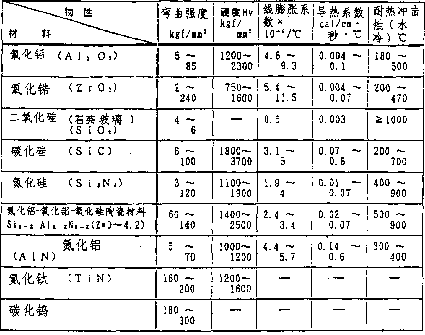
上述陶瓷材料具有超高耐热性,虽然其绝热性不如树脂材料,但线膨胀系数比树脂材料小1/10左右,因而阀元件之间的间隙比较小,可以提供间隙精度高的阀装置。The above-mentioned ceramic material has ultra-high heat resistance. Although its thermal insulation is not as good as that of resin material, its linear expansion coefficient is about 1/10 smaller than that of resin material, so the gap between valve elements is relatively small, and a valve device with high gap accuracy can be provided.
如上所述,将线膨胀系数较小、具有绝热性、抗热冲击性至少在约100℃以上、考虑到安全性最好是约200℃以上的材料用于阀体,可以提高阀元件之间的间隙精度,即使用于将冷/热水混合的使用温差较大的阀装置,仍然能提供磨损小、转矩低且寿命长的阀装置。As mentioned above, using a material with a small linear expansion coefficient, thermal insulation, and thermal shock resistance at least above about 100°C, and preferably above about 200°C in consideration of safety, can improve the gap between valve components. Excellent clearance accuracy, even if it is used for the valve device with a large temperature difference for mixing cold/hot water, it can still provide a valve device with low wear, low torque and long life.
在陶瓷类材料中有代表性的细陶瓷—氧化铝(Al2O3),取决于晶形和所使用的添加剂等,除了上述特性外有时还具有下面表2中所示的特性,该材料具有良好的机械强度、耐热性、尺寸稳定性等阀装置的阀所必备的性能,价格比较平均,综合性能好。Alumina (Al 2 O 3 ), a representative fine ceramic among ceramic materials, sometimes has the properties shown in Table 2 below in addition to the above-mentioned properties, depending on the crystal form and additives used, etc., and this material has Good mechanical strength, heat resistance, dimensional stability and other necessary properties of the valve device, the price is relatively average, and the overall performance is good.
表2
由压缩强度、弯曲强度、硬度、线膨胀系数、导热率、耐热冲击性等在上述范围内的陶瓷材料构成的阀体具有足够的弯曲强度和硬度,即使承受例如17.5kgf/cm2的水压,也不会发生变形,另外,由于具有良好的绝热性和耐热冲击性,热量不易散失,可以保持稳定的水温,即使同时暴露于约100℃的沸水和低温的凉水中时,阀体仍具有足够的耐热冲击性,同时还具有耐腐蚀性。A valve body made of a ceramic material with compressive strength, bending strength, hardness, coefficient of linear expansion, thermal conductivity, thermal shock resistance, etc. within the above range has sufficient bending strength and hardness, even if it bears water of, for example, 17.5kgf/ cm2 In addition, due to its good heat insulation and thermal shock resistance, the heat is not easily lost, and the water temperature can be kept stable. Even when exposed to boiling water at about 100°C and cold water at a low temperature Still has sufficient thermal shock resistance, while also being corrosion resistant.
在阀装置的阀座或阀体由规定的树脂组合物构成的本发明中,阀座或阀体至少有一方是由规定量的聚氰基芳基醚树脂和平均粒径在25μm以下的玻璃状碳构成的树脂组合物的成形体,因而该阀座或阀体的润滑性和耐磨性得到提高并且抗机械冲击和热冲击性能得到增强。另外,作为填充剂的玻璃状碳不存在各向异性,因此阀座和阀体在滑动接触面表面光洁度、平面度、尺寸精度等方面可以以极高的精度成形。In the present invention in which the valve seat or the valve body of the valve device is composed of a prescribed resin composition, at least one of the valve seat or the valve body is made of a prescribed amount of polycyanoarylether resin and glass with an average particle diameter of 25 μm or less. A molded body of a resin composition composed of carbon-like carbon, so that the lubricity and wear resistance of the valve seat or valve body are improved and the resistance to mechanical shock and thermal shock is enhanced. In addition, glassy carbon as a filler has no anisotropy, so the valve seat and valve body can be formed with extremely high precision in terms of surface finish, flatness, dimensional accuracy, etc. of the sliding contact surface.
因此,安装了上述阀座和阀体的阀装置在长期连续使用时可以确保满足实用要求的止水性和操作性。Therefore, the valve device installed with the above-mentioned valve seat and valve body can ensure water-tightness and operability meeting practical requirements during long-term continuous use.
另外,阀装置的阀体或阀座采用在上述树脂组合物中添加PTFE粉末得到的树脂组合物时,可以提高滑动性,减小阀装置的手柄转矩,同时还可以消除手柄操作时容易产生的滑动音(噪音)。In addition, when the valve body or the valve seat of the valve device adopts the resin composition obtained by adding PTFE powder to the above-mentioned resin composition, the sliding property can be improved, the handle torque of the valve device can be reduced, and at the same time, it can also eliminate the tendency to occur when the handle is operated. sliding sound (noise).
其次,在阀座的与阀体相对的表面上设置比阀体直径小的突起部而得到的阀装置,在止水时即使由于作用在阀座上的给水压而使阀座变形,阀座上也只有外周部分变形,上述突起部分仍与阀体保持接触,不会发生漏水。Secondly, the valve device obtained by providing a protrusion smaller than the diameter of the valve body on the surface of the valve seat opposite to the valve body, even if the valve seat is deformed due to the water supply pressure acting on the valve seat when the water is stopped, the valve will not be damaged. Only the peripheral part is deformed on the seat, and the above-mentioned protruding part is still in contact with the valve body, so water leakage will not occur.
阀体的与阀座相对的滑动接触面由陶瓷制成、阀体的与密封部件相对的滑动接触面由滑动性比陶瓷好的合成树脂制成的阀装置,除了上述效果之外,阀体与密封部件的滑动性也得到改善,因而阀体在阀壳内长期保持液密密封,不会漏水,操作手柄移动阀体时比较轻便。The sliding contact surface of the valve body opposite to the valve seat is made of ceramics, and the sliding contact surface of the valve body opposite to the sealing member is made of synthetic resin with better sliding properties than ceramics. In addition to the above effects, the valve body Slidability with the sealing parts is also improved, so the valve body maintains a liquid-tight seal in the valve case for a long time without water leakage, and it is relatively light to operate the handle to move the valve body.
在阀座的突起部分的与阀体接触的滑动面上开设孔的阀装置,阀座与阀体的接触面积减小,可以减小阀体的滑动阻力,使手柄的操作更为轻便。The valve device with a hole on the sliding surface of the protruding part of the valve seat that is in contact with the valve body can reduce the contact area between the valve seat and the valve body, which can reduce the sliding resistance of the valve body and make the handle easier to operate.
在手柄保持器的与阀体的滑动接触面上形成若干个同心圆状沟槽的阀装置,彼此独立的环形滑动接触面分别起到堤防的作用,可以防止流体从滑动接触面的外周缘进入内周缘,提高防止漏水的效果。A valve device in which several concentric circular grooves are formed on the sliding contact surface of the handle holder and the valve body, and the independent annular sliding contact surfaces act as embankments respectively, which can prevent fluid from entering from the outer periphery of the sliding contact surface The inner periphery improves the effect of preventing water leakage.
在这种情况下,如果把阀体的与手柄保持器滑动接触的表面制成内周缘比外周缘隆起的中间高的形状,则手柄的操作更为轻便。In this case, if the surface of the valve body which is in sliding contact with the handle holder is shaped such that the middle of the inner periphery is raised higher than the outer periphery, the handle can be handled more easily.
另外,如果上述沟槽中保持有润滑油或润滑脂,则除了防止泄漏的效果外,还可以减小阀座的滑动阻力,进一步提高阀装置的操作性。In addition, if lubricating oil or grease is held in the groove, in addition to the effect of preventing leakage, the sliding resistance of the valve seat can be reduced, and the operability of the valve device can be further improved.
上述将手柄保持器的与阀体滑动接触的表面制成内周缘比外周缘隆起的中间高形状的阀装置,由于在将部件装入阀装置的状态下所产生的阀壳与底板的压紧力,上述中间高的形状变为平面状,使上述手柄保持器的滑动接触面与阀体紧密地接触。The above-mentioned valve device in which the surface of the handle holder in sliding contact with the valve body is made into a middle height shape in which the inner peripheral edge is higher than the outer peripheral edge, due to the compression of the valve housing and the bottom plate generated when the components are installed in the valve device Force, the shape of the above-mentioned middle height becomes flat, so that the sliding contact surface of the above-mentioned handle holder is in close contact with the valve body.
因此,在使用状态下滑动接触环上承受流出的液体压力负荷时,流过阀壳内的流体不容易从阀座的阀体之间泄漏出来。Therefore, when the sliding contact ring bears the pressure load of the outflowing liquid in the use state, the fluid flowing through the valve casing is not easy to leak out from between the valve body of the valve seat.
实施例1-8和比较例1-9Examples 1-8 and Comparative Examples 1-9
实施例1-8和比较例1-9中使用的原材料汇总表示如下,其中,( )内是表中使用的缩写词,配比全部用重量%表示。The raw materials used in Examples 1-8 and Comparative Examples 1-9 are summarized as follows, wherein, inside ( ) are abbreviations used in the table, and the proportioning ratios are all expressed in % by weight.
(1)聚氰基芳基醚树脂(PEN)(1) Polycyanoaryl ether resin (PEN)
出光兴产社制:ID300 Manufactured by Idemitsu Kosan Co., Ltd.: ID300
(2)玻璃状碳(GC)(2) Glassy carbon (GC)
钟纺社制:BELL-PEARL C-2000Bell Spinning Co.: BELL-PEARL C-2000
(3)再生四氟乙烯树脂(PTFE)(3) Regenerated tetrafluoroethylene resin (PTFE)
喜多村社制:TFE-KT400HKita village system: TFE-KT400H
(4)超高分子量聚乙烯(PE)(4) Ultra-high molecular weight polyethylene (PE)
三井石油化学社制:LUBMER,注塑成形级Manufactured by Mitsui Petrochemical Corporation: LUBMER, injection molding grade
(5)聚苯硫醚树脂(PPS)(5) Polyphenylene sulfide resin (PPS)
Tohpren社制:T-4Tohpren system: T-4
(6)聚醚酰亚胺树脂(PEI)(6) Polyetherimide resin (PEI)
美国通用电气公司制造:ULTEM1000Manufactured by General Electric Company of the United States: ULTEM1000
(7)聚醚砜树脂(PES)(7) Polyethersulfone resin (PES)
英国ICI公司制造:VICTREX4800PManufactured by British ICI company: VICTREX4800P
(8)碳纤维(CF)(8) carbon fiber (CF)
东丽公司制造:BESFIGHTHTA,纤维直径7.2Manufactured by Toray: BESFIGHTHTA, fiber diameter 7.2
μm,拉伸伸长率1.52%μm, tensile elongation 1.52%
(9)云母(9) Mica
加拿大Mica公司制:MICA S-200,平均粒径60Manufactured by Canada Mica Corporation: MICA S-200, average particle size 60
μmμm
按下述方法制造可以在图1所示结构(其中,阀座的上表面为平面)的阀装置中安装的阀体(与图3所示的外形相同)。A valve body (the same shape as that shown in FIG. 3 ) which can be installed in the valve device of the structure shown in FIG. 1 (wherein the upper surface of the valve seat is flat) is manufactured as follows.
按表3和表4中所示的配比将各种原料预先干式混合,然后装入双螺杆挤出机(池贝铁工社制:PCM-30),挤出造粒。使用规定的模将所得粒料注塑成形,用平面磨床加工成形阀体的接触面,提高平面度,再用研磨机充分降低表面粗糙度(Ra0.1-0.2μm)。Various raw materials were preliminarily dry-blended according to the proportions shown in Table 3 and Table 4, and then loaded into a twin-screw extruder (manufactured by Ikegai Iron Works: PCM-30), extruded and granulated. The obtained pellets are injection-molded using a specified mold, and the contact surface of the formed valve body is processed by a surface grinder to improve flatness, and then the surface roughness (Ra0.1-0.2 μm) is sufficiently reduced by a grinder.
将所得到的阀体与用陶瓷制成的阀座组合安装在阀装置中,进行下述的性能试验,观察止水性、操作性、划伤性和因吸水而引起的变形性,结果列于表3和表4中。The obtained valve body and the valve seat made of ceramics were combined and installed in the valve device, and the following performance tests were carried out to observe the water-stopping performance, operability, scratches and deformation caused by water absorption. The results are listed in Table 3 and Table 4.
性能试验performance test
(1)止水性和操作性(1) Waterproof and operability
将阀装置安装到图6所示的单手柄混合水龙头中,考察止水性和操作性。The valve unit was installed in the single-handle mixer faucet shown in Fig. 6, and the water-tightness and operability were examined.
止水性的测定是使手柄处于中央下部(即止水状态),用泵加水压至17.5kgf/cm2,保持30秒,然后测定因漏水而引起的压力降低量(kgf/cm2)。压力降低量在0.3kgf/cm2以下判定为良好。The measurement of water-stopping performance is to put the handle at the lower part of the center (that is, the water-stopping state), apply water pressure to 17.5kgf/cm 2 with a pump, keep it for 30 seconds, and then measure the pressure drop (kgf/cm 2 ) caused by water leakage. A pressure drop of 0.3 kgf/cm 2 or less was judged to be good.
操作性是用转矩测定器(Simpo工业社制:DFG-2K)测定手柄的上下(止水、放水、流量调节)、左右(水温调节)的转矩。转矩测定值(操作力)在300-1000gf范围内判定为良好。转矩小于300gf时,在使用过程中手柄因自重下降,因而不合要求;转矩超过1000gf时,手柄的操作性不够圆滑,因而适宜的范围是400-800gf。Operability is to measure the torque of the handle up and down (water stop, water discharge, flow adjustment) and left and right (water temperature adjustment) with a torque measuring device (manufactured by Simpo Industries: DFG-2K). The measured torque value (operating force) was judged to be good in the range of 300 to 1000 gf. When the torque is less than 300gf, the handle will drop due to its own weight during use, so it does not meet the requirements; when the torque exceeds 1000gf, the operability of the handle is not smooth enough, so the suitable range is 400-800gf.
通过以下所述的初期试验、耐久试验和吸水试验证实上述止水性和操作性。The above-mentioned waterproofness and operability were confirmed by an initial test, a durability test, and a water absorption test described below.
①初期试验:在耐久试验之前测定初期的止水性和操作性。①Initial test: measure the initial waterproofness and operability before the durability test.
②耐久试验:使用在初期试验中使用过的阀体,将手柄连接到耐久试验机(NTN精密树脂社制)上,如图6所示,手柄由右端上部Ru(止水)→右端下部Rd(冷水)→左端下部Ld(水温90℃)→左端上部Lu(止水)→左端下部Ld(水温90℃)→中央下部Cd(温水45℃)→中央上部Cu(止水)→中央下部Cd(温水45℃)→右端下部Rd(冷水)→右端上部Ru(止水)为一个循环(需要25秒左右),进行试验,确认10万次循环和20万次循环后的止水性和操作性。另外,对于止水性降低者不进行上述耐久试验。②Durability test: Use the valve body used in the initial test, and connect the handle to the durability tester (manufactured by NTN Precision Plastic Co., Ltd.), as shown in Figure 6, the handle is from the upper right end Ru (water stop) to the right lower end Rd (Cold water) → Ld at the lower left end (water temperature 90°C) → Lu at the upper left end (water stop) → Ld at the lower left end (water temperature at 90°C) → Cd at the lower center (warm water at 45°C) → Cu at the upper center (water stop) → Cd at the lower center (Warm water at 45°C) → lower right end Rd (cold water) → upper right end Ru (water stop) is a cycle (it takes about 25 seconds), and the test is carried out to confirm the water stop performance and operability after 100,000 cycles and 200,000 cycles . In addition, the above-mentioned durability test was not performed on those whose water-stopping properties were lowered.
③吸水试验:将阀体在热水(90℃)中浸渍200小时,然后测定止水性和操作性。③Water absorption test: Immerse the valve body in hot water (90°C) for 200 hours, and then measure the water-tightness and operability.
(2)划伤性(2) Scratchability
由流入路每分钟流入8升水和1g平均粒径3μm的金属片(刨屑),使手柄与上述耐久试验同样动作,进行10次循环操作。然后,用表面粗糙度测试仪(日本真空社制:DektakII)测定阀体的滑动接触面,测定结果分三级进行评定,即完全没有划伤标记为○,划伤深度小于1μm标记为△,划伤深度大于1μm标记为×。8 liters of water and 1 g of metal flakes (shavings) with an average particle diameter of 3 μm were flowed in per minute from the inflow path, and the handle was operated in the same manner as the above-mentioned durability test, and 10 cycles were performed. Then, use a surface roughness tester (Nippon Vacuum Corporation: DektakII) to measure the sliding contact surface of the valve body. The measurement results are divided into three levels for evaluation, that is, no scratches are marked as ○, and the scratch depth is less than 1 μm as △, Scratch depth greater than 1 μm is marked as ×.
(3)因吸水而引起的变形性(3) Deformability due to water absorption
在初期和阀体在热水(90℃)中浸渍200小时后,用表面粗糙度测试仪测定阀体的滑动接触面的表面形状,分三级评定测试结果,滑动接触面的形状变化小于3μm标记为○,形状变化在3μm-5μm之间标记为△,形状变化在5μm以上标记为×。At the initial stage and after the valve body is immersed in hot water (90°C) for 200 hours, use a surface roughness tester to measure the surface shape of the sliding contact surface of the valve body, and evaluate the test results in three levels. The shape change of the sliding contact surface is less than 3 μm Mark as ○, shape change between 3 μm and 5 μm is marked as △, shape change above 5 μm is marked as ×.
表3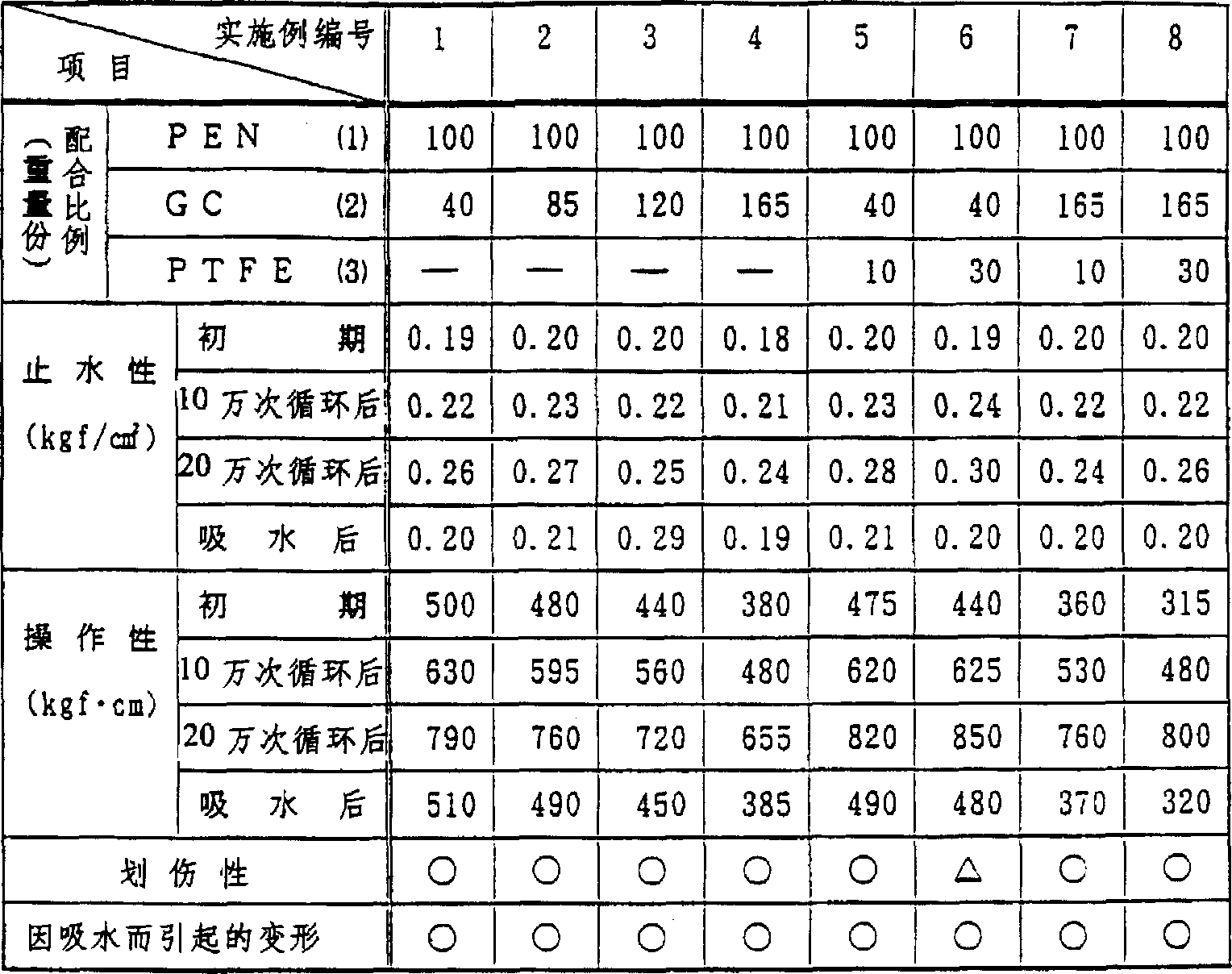
表4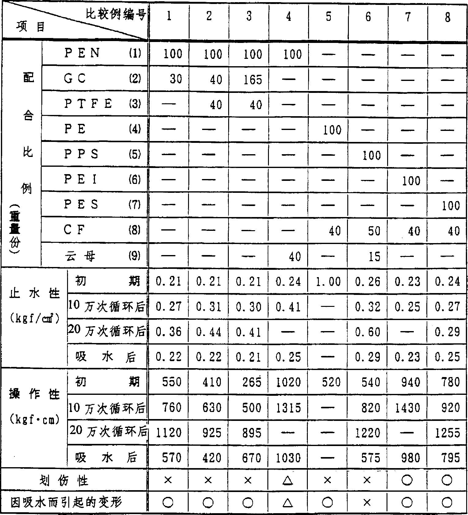
由表3和表4的结果可以看出,实施例1-8在性能试验的初期试验中都显示出良好的止水性、操作性,在20万次循环后的耐久试验结果也良好,止水性是压力下降量为0.3kgf/cm2以下,操作性是转矩测定值在300-1000gf范围内。另外,未发现因吸水而对止水性、操作性和形状变形性产生影响。As can be seen from the results in Table 3 and Table 4, Examples 1-8 all showed good water-stopping properties and operability in the initial test of the performance test, and the results of the durability test after 200,000 cycles were also good, and the water-stopping properties The pressure drop is 0.3kgf/cm 2 or less, and the operability is that the measured torque value is in the range of 300-1000gf. In addition, no influence on water-stopping properties, handleability, and shape deformability due to water absorption was found.
添加了PTFE粉末的实施例5-8,与未添加该粉末的情况相比,操作起来要轻便一些。Examples 5-8, in which PTFE powder was added, were easier to handle than those in which the powder was not added.
在划伤性方面,只有实施例6(每100份(重量)PEN添加40份(重量)玻璃状碳和30份(重量)PTFE粉末)发现很少量的划伤,但对性能没有产生任何影响。In terms of scratchability, only Example 6 (adding 40 parts by weight of glassy carbon and 30 parts by weight of PTFE powder per 100 parts by weight of PEN) found a small amount of scratches, but did not have any effect on performance. Influence.
另一方面,在每100份(重量)PEN添加30份(重量)玻璃状碳而构成的比较例1中,作为止水性指标的压力下降量超过0.3kgf/cm2,操作性指标也上升到1000gf以上。On the other hand, in Comparative Example 1 in which 30 parts by weight of glassy carbon were added to 100 parts by weight of PEN, the pressure drop as an index of water-tightness exceeded 0.3 kgf/cm 2 , and the operability index also rose to More than 1000gf.
添加了40份(重量)PTFE粉末的比较例2和比较例3,止水性和划伤性的结果都很差。另外,在PEN中添加了云母的比较例4、在PPS中添加了碳纤维和云母的比较例6、在PEI中添加了碳纤维的比较例7和在PES中添加了碳纤维的比较例8,操作性都非常不好,不适合于实用。另外,在PE中添加了碳纤维的比较例5,止水性显著恶化。In Comparative Example 2 and Comparative Example 3 in which 40 parts by weight of PTFE powder was added, the results of water-stopping property and scratch resistance were poor. In addition, comparative example 4 in which mica was added to PEN, comparative example 6 in which carbon fiber and mica were added to PPS, comparative example 7 in which carbon fiber was added to PEI, and comparative example 8 in which carbon fiber was added to PES, the operability Both are very bad and not suitable for practical use. In addition, in Comparative Example 5 in which carbon fibers were added to PE, the water-blocking property deteriorated remarkably.
实施例9-11和比较例9Embodiment 9-11 and comparative example 9
参照图1-3说明实施例9。
图1-3中所示的实施例9与图9中所示的现有技术例的不同之处在于阀座6的上表面上形成了用于与阀体滑动接触的圆形突起部12,该突起部的直径比阀体11的直径小。
即,实施例9的结构是在圆筒形的阀壳1的内侧下部安装有底板2,在底板2上安装有2个密封部件3,以各密封部件3的内侧作为流入口4a、4b。That is, the structure of
将圆板形的阀座6叠放在底板2上。在阀座6的外周上沿轴向开设槽8,另一方面,在底板2的外周上形成突起条9,该突起条9与槽8配合可以制止阀座6转动。在阀座6上设置与上述流入口4a、4b连通的二个阀孔10a、10b。The disc-shaped
阀座6用由80%(重量)聚苯硫醚树脂(PPS)和20%(重量)碳纤维组成的合成树脂制成。The
设置在阀体11上面的手柄保持器14可以相对于阀壳1自由转动,安装在其外周下部的密封部件15a与阀壳1的内周面接触,防止漏水。另外,在手柄保持器14的下面安装有由高密度聚乙烯(HMWPE)制成的环形密封部件15b,密封部件15b与阀体11的上面接触,将手柄保持器14和阀体11之间密封住。The
在手柄保持器14上形成上下贯通的轴插入孔16,在穿过该轴插入孔16的手柄轴17的中间部位,通过销子18将其支承住,使其可以在手柄保持器14中自由转动。On the
在手柄轴17的下部设有连接轴部19,该连接轴部19被插入到在阀体11的上面形成的插入孔21中。A connecting
因此,使手柄轴17以销子18为中心摇动时,阀体11沿着阀座6的上表面滑动。此时,如果使手柄轴17以该轴心为中心转动,则手柄保持器14旋转,支承手柄轴17的销子18的方向发生改变,从而可以使手柄轴17在任意方向上摇动,可以使阀体11在该手柄轴17的摇动方向上滑动。Therefore, when the
上述阀体11用氧化铝陶瓷制成,在其外周面与阀壳1的内周面之间形成的混合室22的部分周壁上设置出口23。The above-mentioned
另外,在阀体11的下面形成二个流路4a、4b,通过阀体11的滑动,使该流路4a、4b与阀座6上的阀孔10a、10b连通或断开。In addition, two
实施例9所示的阀装置由于采用了上述结构,在供水时通过手柄轴17的摇动和旋转,使阀体11沿着突起部12的上面滑动,将该阀体11上形成的二个流路24与阀座6上设置的二个阀孔10a、10b连通。Because the valve device shown in
流路24与阀孔10a、10b连通后由底板2上的二个流入口4a、4b中的一个流入口供入的热水和由另一流入口供入的冷水从阀孔10a、10b和流路24流入混合室22,在该混合室22中混合后,由出口23流出。After the
这样,如果预先在出口23上连接喷头,就可以给该淋浴喷头供给热水。In this way, if a shower head is connected to the
要停止供给热水时,操作手柄,移动手柄轴,使阀体11滑动,切断流路24与阀孔10a、10b的连通。To stop hot water supply, operate the handle, move the handle shaft, slide the
下面参照图4-5说明实施例10。
实施例10的阀装置中,阀体25的与阀座26相对的滑动接触面由氧化铝陶瓷层25a构成,同时,阀体25上面的与环形高密度聚乙烯制成的密封部件27b相对的滑动接触面是由80%(重量)聚苯硫醚树脂(PPS)和20%(重量)碳纤维组成的合成树脂层25b构成的,除此之外,其结构与实施例1相同。In the valve device of
为了使陶瓷层25a和合成树脂层25b叠合一体化,可以采用将陶瓷形成凸形、将合成树脂形成凹形然后通过压入成为一体化的方法,或者将合成树脂在配置陶瓷的金属模内注塑成形即所谓的嵌件成形,或者用粘接剂将两个部件粘接,用超声波等使之热熔合成为一体化。In order to make the
实施例11的阀装置中,如图1-3中的点划线所示,在突起部12上形成了轴向的通孔13,除此以外其结构与实施例9完全相同。In the valve device of the eleventh embodiment, as shown by the dotted line in Figs. 1-3, the axial through-
比较例9是图9中所示的现有技术阀装置,它与实施例9的不同之处在于阀座44上面的阀体滑动部上没有形成突起部。Comparative Example 9 is a prior art valve device shown in FIG. 9 , which differs from
按照与上述方法完全相同的试验方法,考察实施例9-11和比较例10的止水性和操作性,结果示于表5中。According to the same test method as the above-mentioned method, the waterproofness and operability of Examples 9-11 and Comparative Example 10 were investigated, and the results are shown in Table 5.
表5
由表5的结果可以看出,与阀体上未形成突起部的比较例10相比,实施例9-11的止水性和操作性均优于前者,这些实施例在水压为17.5kgf/cm2时的压力下降量是0.3kgf/cm2以下,另外,手柄转矩(操作性)也在300-1000gf的范围内。特别是阀体由陶瓷层和合成树脂层两层构成的实施例10的操作性极好,使用稳定性也非常好。As can be seen from the results in Table 5, compared with Comparative Example 10 in which no protrusions are formed on the valve body, Examples 9-11 are superior to the former in terms of water-tightness and operability. The pressure drop at cm 2 is 0.3kgf/cm 2 or less, and the handle torque (operability) is also in the range of 300-1000gf. In particular, Example 10, in which the valve body is composed of two layers of a ceramic layer and a synthetic resin layer, has excellent operability and excellent stability in use.
实施例12Example 12
参照图7和图8说明实施例12和比较例10。Example 12 and Comparative Example 10 will be described with reference to FIGS. 7 and 8 .
实施例12的阀装置与图1-2所示的实施例9相比只有以下两点不同,即阀座31的上面没有形成突起部,另外,在手柄保持器32的下端的与阀体34的滑动接触面上形成了若干个同心圆状的沟槽33。该装置中与实施例9相同的部件在图中用相同符号表示,省略了符号的说明。Compared with
上述手柄保持器32下端的环形接触面形成内周缘17a比外周缘突起10-20μm的中间高的形状,阀体34的与手柄保持器32的滑动接触面(图中的上面)也形成中央部分比周缘部分突起3-8μm的中间高的形状,沟槽33内保持有硅氧烷润滑脂。另外,阀体34由氧化铝陶瓷制成,手柄保持器32由HMWPE制成。The annular contact surface at the lower end of the above-mentioned
沟槽33的断面是V字形,其尺寸为,沟宽0.5mm、深0.6mm,各沟槽以0.7mm的等间距配置。这些沟槽的断面形状除了V字形外,也可以是U字形、矩形或其它已知的形状,另外,只要能起到防止漏水的效果,沟槽的数量及其直径改变成上述数值以外也是可以的。The
比较例10Comparative Example 10
比较例10是由与图9所示的现有技术例完全相同的结构构成的阀装置,与实施例12相同,阀体由氧化铝陶瓷制成,手柄保持器由HMWPE制成。Comparative Example 10 is a valve device having exactly the same structure as the prior art example shown in FIG. 9 . Like Example 12, the valve body is made of alumina ceramics, and the handle holder is made of HMWPE.
采用上述试验方法考察实施例12和比较例10的止水性和操作性,结果列于表6中。The water-tightness and operability of Example 12 and Comparative Example 10 were investigated by the above-mentioned test method, and the results are listed in Table 6.
表6*kgf/cm2**kgf·cmTable 6 *kgf/cm 2 **kgf·cm
由表6的结果可以看出,与比较例10的现有技术阀装置相比,在手柄保持器下部的与阀体滑动接触的滑动接触面上形成若干个同心圆状沟槽的实施例12具有良好的止水性和操作性。It can be seen from the results in Table 6 that, compared with the prior art valve device of Comparative Example 10, Example 12 in which several concentric circular grooves are formed on the sliding contact surface at the lower part of the handle holder that is in sliding contact with the valve body It has good water-tightness and operability.
在工业上的应用性Applicability in industry
如上所述,阀座和阀体至少有一方是由规定量的聚氰基芳基醚树脂和一定粒径的玻璃状碳组成的树脂组合物的成形体的本发明的阀装置,阀座的阀体可以精密成形,没有尺寸误差且耐磨性良好,在使用过程中滑动接触面的表面粗糙度不易增大,有异物侵入时也难以造成划伤。As mentioned above, at least one of the valve seat and the valve body is a molded body of a resin composition composed of a predetermined amount of polycyanoaryl ether resin and glassy carbon with a certain particle size. In the valve device of the present invention, the valve seat The valve body can be precisely formed, has no dimensional error and has good wear resistance, and the surface roughness of the sliding contact surface is not easy to increase during use, and it is difficult to cause scratches when foreign matter invades.
这样的阀装置的优点是安装了具有良好抗蠕变性等机械性能和自润滑性的阀体和阀座,长时间连续使用时可以充分改善止水性,同时调节水量时手柄的操作性也非常好。The advantage of such a valve device is that it is installed with a valve body and a valve seat with good mechanical properties such as creep resistance and self-lubricating properties, which can fully improve the water-stop performance when used continuously for a long time, and the operability of the handle when adjusting the water volume is also very good. good.
在阀座的与阀体相对的表面上设置阀体滑动用的突起部、该突起部的直径比阀体外径小的阀装置,止水时即使由于给水压引起阀座变形,变形部位也只是在阀座的外周部分,因此其突起部与阀体保持接触状态,可以防止由阀体和阀座之间漏水。The surface of the valve seat opposite to the valve body is provided with a protrusion for valve body sliding. The diameter of the protrusion is smaller than the valve body diameter of the valve device. It is only on the outer peripheral part of the valve seat, so its protrusion is kept in contact with the valve body, which can prevent water leakage from between the valve body and the valve seat.
另外,阀体由陶瓷材料制成、阀座由合成树脂制成、阀座上形成直径比阀体外径小的阀体滑动用的突起部的阀装置,阀体滑动时的阻力极小,并能防止因阀座磨损而引起的阀体粘连,使阀体滑动时的手柄操作长期保持良好状态。In addition, the valve device in which the valve body is made of ceramic material, the valve seat is made of synthetic resin, and the valve seat is formed with a protrusion for valve body sliding whose diameter is smaller than the valve outer diameter, the resistance when the valve body slides is extremely small, and It can prevent the sticking of the valve body caused by the wear of the valve seat, and keep the handle operation in good condition for a long time when the valve body slides.
阀体的与阀座相对的滑动接触面由陶瓷材料制成、阀体的与手柄保持器下部的密封部件相对的滑动接触面由合成树脂制成的阀装置,由于改善了阀体与密封部件的滑动性,因而不会漏水,使阀体移动时的手柄操作也更加轻便。另外,在突起部的阀体滑动面上形成孔的阀装置可以进一步减小阀体的滑动阻力,使阀体滑动时更加圆滑。The sliding contact surface of the valve body opposite to the valve seat is made of ceramic material, and the sliding contact surface of the valve body opposite to the sealing part of the lower part of the handle holder is made of synthetic resin. Excellent sliding, so there is no water leakage, and the handle operation is easier when the valve body is moved. In addition, the valve device in which holes are formed on the valve body sliding surface of the protrusion can further reduce the sliding resistance of the valve body, making the valve body slide more smoothly.
在手柄保持器下部的与阀体滑动接触的滑动接触面上形成若干同心圆状沟槽的阀装置,操作性不受损害,并且在使用过程中水等流体不容易从阀体与手柄保持器的滑动接触面泄漏。The valve device with several concentric circular grooves is formed on the sliding contact surface of the lower part of the handle holder that is in sliding contact with the valve body, so that the operability is not damaged, and fluids such as water are not easy to flow from the valve body and the handle holder during use. Leakage of the sliding contact surface.
另外,如果把手柄保持器上形成沟槽的滑动接触面制成中间高的形状,将其装入阀壳内、加上压紧力时,滑动接触面变得极为平滑,可以进一步提高防止漏水效果。In addition, if the sliding contact surface of the groove formed on the handle holder is made into a shape with a middle height, when it is installed in the valve case and a pressing force is applied, the sliding contact surface becomes extremely smooth, which can further improve the prevention of water leakage. Effect.
在上述的阀装置中,在沟槽内保持有润滑剂或润滑脂时,除了前述防止漏水的效果外,还可以进一步减小手柄保持器的滑动阻力,使操作性能更好。In the above valve device, when lubricant or grease is held in the groove, in addition to the above-mentioned effect of preventing water leakage, the sliding resistance of the handle holder can be further reduced, resulting in better operability.
Claims (6)
Applications Claiming Priority (9)
| Application Number | Priority Date | Filing Date | Title |
|---|---|---|---|
| JP62730/1994 | 1994-03-31 | ||
| JP6273094 | 1994-03-31 | ||
| JP62730/94 | 1994-03-31 | ||
| JP34019794 | 1994-12-29 | ||
| JP34019694 | 1994-12-29 | ||
| JP340196/94 | 1994-12-29 | ||
| JP340197/94 | 1994-12-29 | ||
| JP340197/1994 | 1994-12-29 | ||
| JP340196/1994 | 1994-12-29 |
Publications (2)
| Publication Number | Publication Date |
|---|---|
| CN1129030A CN1129030A (en) | 1996-08-14 |
| CN1051606C true CN1051606C (en) | 2000-04-19 |
Family
ID=27297938
Family Applications (1)
| Application Number | Title | Priority Date | Filing Date |
|---|---|---|---|
| CN95190421A Expired - Lifetime CN1051606C (en) | 1994-03-31 | 1995-03-31 | Valve device |
Country Status (5)
| Country | Link |
|---|---|
| US (1) | US5755261A (en) |
| CN (1) | CN1051606C (en) |
| CA (1) | CA2164111C (en) |
| DE (1) | DE19580519B3 (en) |
| WO (1) | WO1995027162A1 (en) |
Cited By (1)
| Publication number | Priority date | Publication date | Assignee | Title |
|---|---|---|---|---|
| CN100373081C (en) * | 2002-08-19 | 2008-03-05 | Toto株式会社 | Disc valve and faucet |
Families Citing this family (39)
| Publication number | Priority date | Publication date | Assignee | Title |
|---|---|---|---|---|
| KR100187398B1 (en) * | 1996-01-09 | 1999-04-15 | 성철기 | Drain device of hot and cool water |
| JP3217696B2 (en) * | 1996-04-26 | 2001-10-09 | 京セラ株式会社 | Disc valve |
| EP0933566A1 (en) * | 1998-02-02 | 1999-08-04 | Maschinenfabrik Sulzer-Burckhardt AG | Sealing for dry-running piston compressor |
| US6173913B1 (en) * | 1999-08-25 | 2001-01-16 | Caterpillar Inc. | Ceramic check for a fuel injector |
| US6286808B1 (en) | 2000-02-25 | 2001-09-11 | Kohler Co. | Gravity flow faucet |
| ITTO20010551A1 (en) * | 2001-06-08 | 2002-12-08 | Gevipi Ag | FLOW CONTROL BODIES IN HARD MATERIAL FOR HYDRAULIC APPLIANCES. |
| US6893003B2 (en) | 2002-04-19 | 2005-05-17 | Newfrey Llc | Valves including thermally sprayed sealing components |
| US8555921B2 (en) | 2002-12-18 | 2013-10-15 | Vapor Technologies Inc. | Faucet component with coating |
| US7866342B2 (en) | 2002-12-18 | 2011-01-11 | Vapor Technologies, Inc. | Valve component for faucet |
| US8220489B2 (en) | 2002-12-18 | 2012-07-17 | Vapor Technologies Inc. | Faucet with wear-resistant valve component |
| US7866343B2 (en) * | 2002-12-18 | 2011-01-11 | Masco Corporation Of Indiana | Faucet |
| US6904935B2 (en) * | 2002-12-18 | 2005-06-14 | Masco Corporation Of Indiana | Valve component with multiple surface layers |
| JP4823488B2 (en) * | 2003-04-30 | 2011-11-24 | 昭和電工株式会社 | High purity ammonia gas supply equipment and supply method |
| JP4412963B2 (en) * | 2003-10-10 | 2010-02-10 | 旭有機材工業株式会社 | Plastic parts for valves |
| KR100797521B1 (en) * | 2006-03-22 | 2008-01-24 | 김종구 | Water valve cartridge |
| JPWO2007116610A1 (en) * | 2006-03-30 | 2009-08-20 | テルモ株式会社 | Medical stopcock |
| US7753074B2 (en) | 2006-07-28 | 2010-07-13 | Masco Corporation Of Indiana | Mixing valve |
| US8578966B2 (en) | 2006-07-28 | 2013-11-12 | Masco Corporation Of Indiana | Mixing valve |
| WO2008031247A1 (en) * | 2006-08-14 | 2008-03-20 | Yongsheng Song | A valve reducing the abrasion between a closing part and a valve seat seal surface when sliding relatively |
| CA2675429C (en) * | 2007-01-31 | 2016-01-12 | Moen Incorporated | Valve cartridge insensitive to installation load |
| US7779865B2 (en) | 2007-04-20 | 2010-08-24 | Kohler Co. | Plumbing valve with undulating disk surface |
| US20090078907A1 (en) * | 2007-09-26 | 2009-03-26 | Honeywell International, Inc. | Composite valve assembly for aircraft environmental control systems |
| DE102008000109A1 (en) * | 2008-01-21 | 2009-07-23 | Ceramtec Ag | cartridge housing |
| WO2010073873A1 (en) * | 2008-12-25 | 2010-07-01 | 京セラ株式会社 | Sliding component and mechanical seal, faucet valve, and rolling support device equipped with same |
| US20110232826A1 (en) * | 2010-03-26 | 2011-09-29 | Sumitomo Chemical Company, Limited | Production method for ceramic-resin composite |
| WO2011134407A1 (en) * | 2010-04-30 | 2011-11-03 | 厦门松霖科技有限公司 | Ball-rod switching shower |
| HUE050926T2 (en) * | 2011-08-10 | 2021-01-28 | Ben Dor Eran | Multiple axis handle and mechanism |
| CN102678949A (en) * | 2012-05-25 | 2012-09-19 | 杨国联 | Valve core structure of tap |
| CN104653816B (en) * | 2013-11-25 | 2017-05-24 | 夏中伟 | Two input and two outlet water mixing valve core with waterway switch function |
| WO2015181020A1 (en) * | 2014-05-26 | 2015-12-03 | Ceramtec Gmbh | Control cartridge with high volumetric flow and variable mixed water outlet |
| CN104747748A (en) * | 2015-03-19 | 2015-07-01 | 辽宁鑫源重工有限公司 | Carbon fiber reinforced plastic ball valve |
| US10697552B2 (en) * | 2017-01-26 | 2020-06-30 | Toto Ltd. | Faucet valve |
| US20190072197A1 (en) * | 2017-09-01 | 2019-03-07 | Jian-Shiou Liaw | Carbon-fiber seat for a pneumatic hammer |
| US11401955B2 (en) | 2018-02-09 | 2022-08-02 | Vat Holding Ag | Piston-cylinder unit |
| AU2018439421B2 (en) * | 2018-08-30 | 2024-11-28 | Takagi Co., Ltd. | Hot and cold water mixing faucet |
| ES2869138T3 (en) * | 2019-02-28 | 2021-10-25 | Fluehs Drehtechnik Gmbh | Valve top for sanitary fittings |
| DE102019003301A1 (en) * | 2019-05-10 | 2020-11-12 | Grohe Ag | Single lever cartridge for a sanitary fitting |
| US20200363379A1 (en) * | 2019-05-14 | 2020-11-19 | Tecan Trading Ag | Non-sticking rotary valve |
| DE102022214438B4 (en) * | 2022-12-29 | 2025-07-17 | Hanon Systems Efp Deutschland Gmbh | Valve for use in a vehicle cooling circuit and method for producing such a valve |
Family Cites Families (29)
| Publication number | Priority date | Publication date | Assignee | Title |
|---|---|---|---|---|
| JPS53127627U (en) * | 1977-03-18 | 1978-10-11 | ||
| US4362186A (en) * | 1981-02-11 | 1982-12-07 | American Standard Inc. | Sanitary fitting |
| US4378029A (en) * | 1981-11-02 | 1983-03-29 | American Standard Inc. | Single control faucet |
| IL73930A (en) * | 1984-12-25 | 1988-12-30 | Hamat Koor Metals Ltd | Mixing device for faucets |
| DE3503793C2 (en) * | 1985-02-05 | 1995-09-21 | Grohe Armaturen Friedrich | Mixing valve |
| US4935313A (en) * | 1985-02-12 | 1990-06-19 | Masco Corporation Of Indiana | Process of manufacturing seal members having a low friction coefficient |
| FR2592127B1 (en) * | 1985-12-20 | 1988-03-18 | Prod Sanitaires Cie Internal | MIXER VALVE |
| JPS633059A (en) * | 1986-06-24 | 1988-01-08 | Idemitsu Kosan Co Ltd | Thermoplastic resin composition |
| JPS6336765U (en) * | 1986-08-26 | 1988-03-09 | ||
| IT1210776B (en) * | 1987-06-01 | 1989-09-20 | Gevipi Ag | CARTRIDGE FOR TAPS WITH PLATES IN HARD MATERIAL WITH METALLIC COATING OF THE SLIDING SURFACES |
| US4942902A (en) * | 1987-09-09 | 1990-07-24 | Masco Corporation | Mixing cartridge faucet with parts that can apply pressure to the valve plates of hard material |
| JPH0696668B2 (en) * | 1988-01-29 | 1994-11-30 | 出光興産株式会社 | Resin composition |
| JPH0355010Y2 (en) * | 1988-02-29 | 1991-12-05 | ||
| JP2703025B2 (en) * | 1989-01-19 | 1998-01-26 | エヌティエヌ株式会社 | Faucet valve device |
| DE3929147A1 (en) * | 1989-09-02 | 1991-03-07 | Grohe Armaturen Friedrich | VALVE BODY |
| IT222582Z2 (en) * | 1989-11-03 | 1995-04-21 | Galatron Srl | CONTROL UNIT FOR FLUID DELIVERY IN HOT AND COLD WATER MIXING VALVES |
| JP2526295Y2 (en) * | 1989-12-15 | 1997-02-19 | 三菱重工業株式会社 | Rotary valve |
| EP0437851A3 (en) * | 1990-01-10 | 1992-01-15 | Idemitsu Kosan Company Limited | Process for preparation of resin composition for powder molding and process for production of powder molded product |
| JP2965309B2 (en) * | 1990-03-14 | 1999-10-18 | エヌティエヌ株式会社 | Hot water mixing faucet |
| JP3044468B2 (en) * | 1990-04-19 | 2000-05-22 | 日本石油化学株式会社 | Sliding resin composition |
| JPH0710949B2 (en) * | 1990-05-16 | 1995-02-08 | 出光興産株式会社 | Resin composition |
| JP2994770B2 (en) * | 1991-03-01 | 1999-12-27 | エヌティエヌ株式会社 | Plastic cage for rolling bearings |
| JPH051777A (en) * | 1991-06-24 | 1993-01-08 | Tokyo Yogyo Co Ltd | On-off valve for hot water |
| JP2568856Y2 (en) * | 1992-03-31 | 1998-04-15 | エヌティエヌ株式会社 | Valve device |
| JP2785577B2 (en) * | 1992-04-16 | 1998-08-13 | 東陶機器株式会社 | Fixed valve disc |
| IT1260745B (en) * | 1992-04-30 | 1996-04-22 | Orlando Bosio | SINGLE-LEVER MIXING CARTRIDGE FOR HOT AND COLD WATER |
| US5518027A (en) * | 1992-09-30 | 1996-05-21 | Ntn Corporation | Valve assembly |
| JPH06213341A (en) * | 1992-10-30 | 1994-08-02 | Ntn Corp | Valve device |
| DE9313271U1 (en) * | 1993-09-03 | 1993-11-04 | Christophery GmbH, 58644 Iserlohn | Single lever mixing valve |
-
1995
- 1995-03-31 CN CN95190421A patent/CN1051606C/en not_active Expired - Lifetime
- 1995-03-31 CA CA002164111A patent/CA2164111C/en not_active Expired - Lifetime
- 1995-03-31 US US08/553,504 patent/US5755261A/en not_active Expired - Lifetime
- 1995-03-31 WO PCT/JP1995/000630 patent/WO1995027162A1/en not_active Ceased
- 1995-03-31 DE DE19580519.4T patent/DE19580519B3/en not_active Expired - Lifetime
Cited By (1)
| Publication number | Priority date | Publication date | Assignee | Title |
|---|---|---|---|---|
| CN100373081C (en) * | 2002-08-19 | 2008-03-05 | Toto株式会社 | Disc valve and faucet |
Also Published As
| Publication number | Publication date |
|---|---|
| US5755261A (en) | 1998-05-26 |
| CA2164111A1 (en) | 1995-12-10 |
| CA2164111C (en) | 2004-10-05 |
| CN1129030A (en) | 1996-08-14 |
| WO1995027162A1 (en) | 1995-10-12 |
| DE19580519B3 (en) | 2014-03-06 |
| DE19580519T1 (en) | 1996-04-25 |
Similar Documents
| Publication | Publication Date | Title |
|---|---|---|
| CN1051606C (en) | Valve device | |
| CN1166733C (en) | transparent elastomer composition | |
| CN1280376C (en) | sealing ring | |
| CN1075003C (en) | Thermoplastic elastomer laminates and glass run channels molded therefrom | |
| KR101522262B1 (en) | Lip seal for water pump | |
| JP2011224731A (en) | Retainer ring and method of manufacturing retainer ring | |
| JP4017671B2 (en) | Low permeability fluid seal for flow control device | |
| CN1777643A (en) | Method for producing low-friction fluorine rubber crosslinked body | |
| CN101080463A (en) | Rubber composition and sealing material for plasma treatment device | |
| US5435348A (en) | Valve assembly | |
| CN1867633A (en) | Resinous member for valve | |
| CN1216931C (en) | Seal ring | |
| CN1976993A (en) | Fluorine-containing elastomer composition and molded article made therefrom | |
| CN1489524A (en) | Elastic member for ink jet recording apparatus, ink cartridge, and ink jet recording apparatus | |
| JP2020106149A (en) | Seal for flow rate control valve and flow rate control valve device | |
| CN1556900A (en) | rolling device | |
| CN1396207A (en) | Flame-retarded resin composition and its forming product | |
| JP2703025B2 (en) | Faucet valve device | |
| JPH03265769A (en) | Hot-water/cool-water mixture water faucet | |
| JP3053756B2 (en) | Underwater slidable resin composition and valve device | |
| JP2018080754A (en) | Gasket around engine and manufacturing method thereof | |
| CN1777644A (en) | Fluorine-containing elastomer composition having excellent effect of preventing plasma aging and molded article thereof | |
| JP2703026B2 (en) | Faucet valve device | |
| JPH09286916A (en) | Underwater slidable resin composition and disk valve for faucet | |
| JPH10184950A (en) | Valve element of valve device or manufacture of valve seat |
Legal Events
| Date | Code | Title | Description |
|---|---|---|---|
| C06 | Publication | ||
| PB01 | Publication | ||
| C10 | Entry into substantive examination | ||
| SE01 | Entry into force of request for substantive examination | ||
| C14 | Grant of patent or utility model | ||
| GR01 | Patent grant | ||
| C17 | Cessation of patent right | ||
| CX01 | Expiry of patent term |
Expiration termination date: 20150331 Granted publication date: 20000419 |