CN1039303C - Method and device for regulating posture of triaxially stable revolving spacecraft - Google Patents
Method and device for regulating posture of triaxially stable revolving spacecraft Download PDFInfo
- Publication number
- CN1039303C CN1039303C CN92111579A CN92111579A CN1039303C CN 1039303 C CN1039303 C CN 1039303C CN 92111579 A CN92111579 A CN 92111579A CN 92111579 A CN92111579 A CN 92111579A CN 1039303 C CN1039303 C CN 1039303C
- Authority
- CN
- China
- Prior art keywords
- nutating
- signal
- spacecraft
- regulating
- dead zone
- Prior art date
- Legal status (The legal status is an assumption and is not a legal conclusion. Google has not performed a legal analysis and makes no representation as to the accuracy of the status listed.)
- Expired - Fee Related
Links
- 230000001105 regulatory effect Effects 0.000 title claims abstract description 113
- 238000000034 method Methods 0.000 title claims abstract description 19
- 230000033001 locomotion Effects 0.000 claims description 28
- 230000014509 gene expression Effects 0.000 claims description 11
- 230000033228 biological regulation Effects 0.000 claims description 9
- 230000007246 mechanism Effects 0.000 claims description 2
- 230000001276 controlling effect Effects 0.000 abstract description 2
- 230000009471 action Effects 0.000 description 20
- 238000006243 chemical reaction Methods 0.000 description 20
- 238000012806 monitoring device Methods 0.000 description 11
- 238000009825 accumulation Methods 0.000 description 10
- 230000000694 effects Effects 0.000 description 10
- 238000012937 correction Methods 0.000 description 9
- 230000007704 transition Effects 0.000 description 9
- 230000005764 inhibitory process Effects 0.000 description 7
- 230000008569 process Effects 0.000 description 7
- 238000010586 diagram Methods 0.000 description 5
- 239000000446 fuel Substances 0.000 description 5
- 230000010355 oscillation Effects 0.000 description 5
- 238000013016 damping Methods 0.000 description 4
- 238000005259 measurement Methods 0.000 description 4
- 235000019892 Stellar Nutrition 0.000 description 3
- 230000015572 biosynthetic process Effects 0.000 description 3
- 238000013461 design Methods 0.000 description 3
- 230000001052 transient effect Effects 0.000 description 3
- 210000001367 artery Anatomy 0.000 description 2
- 230000008859 change Effects 0.000 description 2
- 230000003203 everyday effect Effects 0.000 description 2
- 230000000737 periodic effect Effects 0.000 description 2
- 230000001141 propulsive effect Effects 0.000 description 2
- 238000003860 storage Methods 0.000 description 2
- 210000003462 vein Anatomy 0.000 description 2
- 241000661823 Canopus Species 0.000 description 1
- 206010048669 Terminal state Diseases 0.000 description 1
- 230000001133 acceleration Effects 0.000 description 1
- 238000004891 communication Methods 0.000 description 1
- 230000003750 conditioning effect Effects 0.000 description 1
- 239000004020 conductor Substances 0.000 description 1
- 230000008878 coupling Effects 0.000 description 1
- 238000010168 coupling process Methods 0.000 description 1
- 238000005859 coupling reaction Methods 0.000 description 1
- 238000003967 crop rotation Methods 0.000 description 1
- 230000003828 downregulation Effects 0.000 description 1
- 239000000428 dust Substances 0.000 description 1
- 238000005516 engineering process Methods 0.000 description 1
- 238000011156 evaluation Methods 0.000 description 1
- 230000006872 improvement Effects 0.000 description 1
- 238000012905 input function Methods 0.000 description 1
- 238000009434 installation Methods 0.000 description 1
- 230000002045 lasting effect Effects 0.000 description 1
- 230000003287 optical effect Effects 0.000 description 1
- 239000002245 particle Substances 0.000 description 1
- 239000013641 positive control Substances 0.000 description 1
- 238000003825 pressing Methods 0.000 description 1
- 230000002441 reversible effect Effects 0.000 description 1
- 238000012552 review Methods 0.000 description 1
- 238000005096 rolling process Methods 0.000 description 1
- 238000007789 sealing Methods 0.000 description 1
- 239000000126 substance Substances 0.000 description 1
- 230000001360 synchronised effect Effects 0.000 description 1
- 239000002699 waste material Substances 0.000 description 1
Images


Classifications
-
- B—PERFORMING OPERATIONS; TRANSPORTING
- B64—AIRCRAFT; AVIATION; COSMONAUTICS
- B64G—COSMONAUTICS; VEHICLES OR EQUIPMENT THEREFOR
- B64G1/00—Cosmonautic vehicles
- B64G1/22—Parts of, or equipment specially adapted for fitting in or to, cosmonautic vehicles
- B64G1/24—Guiding or controlling apparatus, e.g. for attitude control
- B64G1/38—Guiding or controlling apparatus, e.g. for attitude control damping of oscillations, e.g. nutation dampers
-
- B—PERFORMING OPERATIONS; TRANSPORTING
- B64—AIRCRAFT; AVIATION; COSMONAUTICS
- B64G—COSMONAUTICS; VEHICLES OR EQUIPMENT THEREFOR
- B64G1/00—Cosmonautic vehicles
- B64G1/22—Parts of, or equipment specially adapted for fitting in or to, cosmonautic vehicles
- B64G1/24—Guiding or controlling apparatus, e.g. for attitude control
- B64G1/244—Spacecraft control systems
-
- B—PERFORMING OPERATIONS; TRANSPORTING
- B64—AIRCRAFT; AVIATION; COSMONAUTICS
- B64G—COSMONAUTICS; VEHICLES OR EQUIPMENT THEREFOR
- B64G1/00—Cosmonautic vehicles
- B64G1/22—Parts of, or equipment specially adapted for fitting in or to, cosmonautic vehicles
- B64G1/24—Guiding or controlling apparatus, e.g. for attitude control
- B64G1/28—Guiding or controlling apparatus, e.g. for attitude control using inertia or gyro effect
- B64G1/281—Spin-stabilised spacecraft
Landscapes
- Engineering & Computer Science (AREA)
- Remote Sensing (AREA)
- Chemical & Material Sciences (AREA)
- Combustion & Propulsion (AREA)
- Radar, Positioning & Navigation (AREA)
- Aviation & Aerospace Engineering (AREA)
- Automation & Control Theory (AREA)
- Control Of Position, Course, Altitude, Or Attitude Of Moving Bodies (AREA)
- Vehicle Body Suspensions (AREA)
Abstract
An attitude regulating method for a rotary spacecraft stable in three axial directions is that keeping rotation direction in an inert space and applying at least one stationary component to restrict the nutation amplitude. The invention is characterized in continually detecting not only the deviation of rotation direction to specified direction but also the nutation amplitude by the stationary component when the specified limit value (plus or minus d Phi, dN) is exceeded, and then when the rotation direction is at the specified allowable limit (plus or minus d Phi), independently controlling the attitude to reduce the nutation.
Description
The method and apparatus that the present invention relates to regulate the hand of rotation of spacecraft and suppress spacecraft nutating vibration, described spacecraft has the torque of accumulation.Various devices were disclosed, these devices for the adjusting of standard value and around rotation axis with respect to two spacecraft body axis (X transverse to rotation axis, the swing of the free-moving swivel Z-axle) is stable, having used one or several to measure first lateral axis (X-axle) and/or second lateral axis (Z-axle) produces with respect to the position transduser of the angular deviation of their desired location with around one or two lateral axis and regulates moment, particularly interrupter duty, its regulating action can not be lower than the regulating element of minimum given pulse increment, as the counteraction jet pipe.A kind of disclosed by WO-89/02622 in these devices is characterized in that, by to one or two lateral axiss its specified angle position deviation (∈ relatively
φ, ∈
φ) measurement signal formed component of signal after adjuster circuit separates, described component of signal has been represented at motion of space inner orbit and hand of rotation (Φ
0φ
0) and nutating (Φ
N), and in rotary actuator and nutating regulating control, be coupled to each other as follows, promptly described first component of signal is determined size, number of times and the symbol of regulating action, expression nutating (Φ
N) the secondary signal component determine in a nutation period regulating action constantly and phase angle (β
N).
The present invention relates to improvement to the X control apparatus of the above-mentioned type.Because these devices have several main shortcomings:
According to the feature of this type of device, regulating action has only in the following cases and just is activated, promptly with the space in standard trajectory (H
x, H
z) between rotating deviation (with the orbiting motion component (Φ of deviation signal
0, φ
0) represent) startup boundary (d that surpass to determine, that give in advance by a dead zone
φ, d
φ), and do not consider nutating amplitude (A with orbiting motion component stack
N) have on earth much.In communication satellite and applied satellite, known technology is, for inclination angle and the attitude of spacecraft on its track that keeps the spacecraft flight track, must do the track correction according to common time gap handles, in this process, distrubing moment acts on the spacecraft, will be when it moves than satellite standard larger about ten power sides of 5, and the result will be used for producing the adjusting moment around the spacecraft body axis with the action of corresponding violent counteraction jet pipe.Behind track correction EO, according to can be around the size of the regulating impulse that provides at last of lateral axis and time command at the above-mentioned type, be adjusted in the transient process of standard operation, simultaneously on arbitrary position of rotating vector, big nutating amplitude particularly appears in above-mentioned dead zone, when surpassing dead band limits, just start the regulating action of equally also impelling best nutating decay subsequently.For be equipped with a revolving wheel fixing, that be generally 50Nms, representative type three axial stable satellites, the distrubing moment 10 under the standard condition of service
-5The Nm effect down, for example can make this residue nutating that is not subjected to positive damping or negative damping vibration the longest lasting 1.2 hours, its prerequisite be hand of rotation just in the scope of giving in advance, allowing by the dead zone (0.025 °), promptly up to rotating deviation from the action boundary in dead zone (as-d
φ) forward to another the action boundary rotating deviation (+d
φ) time for this reason.When the action boundary was bigger, above-mentioned time length also can correspondingly prolong.During this period of time, the residue nutating that is not subjected to damping will destroy the error correction plan that is used for the attitude adjusting in undesirable mode.
In addition, the lateral axis of only regulating this class spacecraft with the counteraction jet pipe moves and has some shortcoming and risk in principle.Producing adjusting moment with chemical actuating device must be associated in the consumption of power fuel, and limited power fuel deposit will influence the flight time.In addition, producing the counteraction jet pipe of regulating square around the spacecraft body axis must play a role at whole life period at least together with affiliated pipeline system, valve etc., this can be directed at waste of fuel and loss due to leakage, for example switch valve contained by power fuel the tiny dust particle plugging time, perhaps when pipe joint and valve union poor sealing, also can damage its reliability.Therefore, in applied satellite, mostly also be provided with in standard in service being used for and make to regulate other power element usefulness, additional around lateral axis, as reaction wheel, V-arrangement revolving wheel or universal framework, be used for regulating accumulation torque and magnetic torquer etc. these power elements or single or suitably combine with respect to the spacecraft body shaft, they produce continuously controllable and regulate moment, and need the regulating control separately of other structure and parameter in traditional system.Dispose the transition period of moving to standard at regulating control and power element with other, owing to exist the starting of oscillation process bigger round-off error will temporarily occur, in order to reduce this error or to suppress this error, often must use additional transition regulating control, this has just improved the undesirable crisscross degree of control system.When using the rotary flyweights of reaction wheel and universal supporting, usually must when surpassing the maxim that allows, eliminate the accumulation torque on lateral axis that causes by external disturbance moment, for example use the magnetic torquer of having mentioned or use the counteraction jet pipe, preferably during the track correction of necessity is handled, realize that under any circumstance requisite reaction driven device starts.The startup of described reaction driven device is particularly used when the drive system of upgrading, as ion engine, plasma jet etc., though they have much higher ratio pulse, but also have little propulsive force simultaneously, therefore, in this case, it is very frequent that the track correction is handled, such as must carry out several hours time every day.
Task of the present invention is, improving one's methods and installing of the above-mentioned type is provided, this device under a tangent condition, can guarantee the best, i.e. the inhibition nutating of the fastest, fuel saving, the transition period after the track correction is handled particularly is promptly when rotating vector is positioned at given permission boundary in the orientation in space.Simultaneously, this device also can be used in the standard operation phase subsequently lateral axis being regulated under the situation of the power element of the continuous working of using other type, and the starting of oscillation process and the transient error that can not occur adding.
This point the present invention is achieved in that promptly, is stipulating directional space (H by the dead zone element continuous review that separates
z, H
x) in the deviation and the nutating amplitude (A of hand of rotation
N) whether above given startup boundary (± d
φ± d
φ, d
N), when the rotating vector and the hand of rotation of spacecraft is positioned at by starting boundary (± d
φ) in the given allowed band time, (regularity that still will explain in detail following after) also only starts regulating action for the inhibition nutating.
In another structure of the present invention, the above-mentioned type for regulate rotation and suppress signal that nutating forms under the situation of avoiding transition to disturb not only in transition period, and subsequently mark in the operation adjusting stage by means of other type, especially the power element of the cited pattern of continuous working directly continuous be used for reducing remaining the residue nutating.
This ad hoc proposal a kind of be used for relate to can be given the regulation attitude aspect three attitude control methods axially stable, the rotation spacecraft, this spacecraft has been equipped power element, be used to produce around two with the rotation axis quadrature, and the adjusting moment of the lateral axis of mutual quadrature, in the method, by means of at least one attitude sensor obtain representative in two lateral axiss, with respect to the angular deviation signal of the angular deviation that requires attitude, form the component of signal (Φ of first expression spacecraft orbit motion by this angular deviation signal
O) and second component of signal (Φ that represents the spacecraft nutation movement
N), use the incoming signal that first component of signal obtains the first dead zone element (204).Use second component of signal and obtain to represent nutating amplitude (A
N) and nutating phase place (β
N) signal, the output signal of these signals and the first dead zone element is defeated by the nutating regulating control of determining to be started by power element the moment of regulating action, it is characterized in that, represents nutating amplitude (A
N) signal also be defeated by the second dead zone element, select the startup boundary (d of the second dead zone element according to the nutating amplitude of high permission that can be given
N), the output signal of the second dead zone element is similarly the nutating regulating control and receives, and this be in to attached as the essentiality of regulating action consider this output signal when decisioing making.
Provide especially again in addition a kind of be used for relate to can be given the regulation attitude aspect three attitude regulating mechanisms axially stable, the rotation spacecraft, this spacecraft has at least one attitude sensor, be used for measuring around two with the rotation axis quadrature and mutually orthogonal lateral axis in one, with respect to the angular deviation of regulation attitude, power element is still arranged, be used to produce adjusting moment, still have one to receive the angular deviation signal (∈ that describes angular deviation around two lateral axiss
φ) and therefore represent spacecraft orbit is moved, the generation first component of signal (Φ
0) the regulating control network, one is used for from angular deviation signal (∈
φ) obtain to represent the secondary signal component (Φ of spacecraft nutation movement
N) first device, one connect after having the first dead zone element, receive the first component of signal (Φ
0) rotary actuator, one is used for from secondary signal component (Φ
N) obtain to represent nutating amplitude (A
N) and nutating phase place (β
N) second device of signal, and be connected to second device and the nutating regulating control of the first dead zone element after one, be used for determining to start the moment of regulating moment, it is characterized in that: have second reception and represent nutating amplitude (A
N) dead zone element signal, that an output signal sent to the nutating regulating control.
Further specify principal character of the present invention by embodiment below.Accompanying drawing is represented:
Fig. 1: represented measuring cell and the possible in principle configuration of power element in three axial stable satellites with accumulation torque with the form of sketch.
Fig. 2 a: only measure the simplified block diagram of rotation and nutating being made the device of adjusting around the position transduser of the angle position of a lateral axis (X-axle) for use one according to the present invention.
Fig. 2 b: for rotation and nutating being made the logical diagram of optimum adjustment according to the present invention.
Fig. 2 c: for be matched with the functional circuit of different system parameter according to having of Fig. 2 a.
Fig. 3 a to 3c: with geometric graph represent one with two to around the phase condition that applies regulating action each nutation period of different satellite body axis.
Fig. 4 a: for of the present invention gesturing around two lateral axiss measured and the device of attitude adjusting.
Fig. 4 b: be the block scheme of regulating with the rotation crop rotation standard operation of counteraction revolving wheel or universal supporting.
Fig. 5: make the phase condition that rotation and nutating are regulated when expression has two regulating actions for each nutation period around X-axis (α=0): at P
1(β
N1) or P
1 *(β
N1 *) time be Δ P
1, at P
2(β
N2, Δ β
N2) time be+Δ P
2Or at P
1Or P
2 *The time be-Δ P
1, at P
2 *The time be-Δ P
2
Fig. 1 represents to be used for to gather and adjusting has accumulation torque (H
y) the lateral axis motion (X-of spacecraft, the Z-axle) configuration that measuring cell and regulating element are possible in principle, this measuring cell and regulating element can be realized the adjusting of spacecraft around its third axle line of no longer discussing later on (Y-axle) by means of this rotary flyweights in a known manner by hard-wired rotary flyweights 107 expressions.In the orientation of demarcating, the z axis of spacecraft should point to the earth's core, X-orientation of its axis sense of motion, and the Y-axis should be perpendicular to the orbit plane energized south.Attitude error (∈ around the X-axis
φ) for example can measure to the earth infrared pickoff 101 of orientation by a Z along spacecraft, positional error around the spacecraft z axis on a large scale can be measured by the sun sensor of suitable configuration, the optical axis of big positive sensor is positioned to the X-Z plane that is parallel to satellite with different directions, and these sun sensors are only represented by a sun sensor along the setting of X coordinate direction in Fig. 1.Known situation is, can be by means of stellar sensor, and preferably the stellar sensor by means of line of vision north (North Star) or line of vision south (Canopus) obtains continuous coordinate and reference yaw system.In Fig. 1, not only show in order to the actuator 103a of generation as regulating element around the adjusting moment of the general pulsed of spacecraft body shaft (X-axle) and yaw axis (Y-axle), 103b, and 104a, 104b, and show reaction wheel 105a, 105b and magnetic torquer 106a, 106b, the pulsed that they not only are suitable for producing around spacecraft body shaft X-axis and Z-axis under control corresponding is regulated moment, and also can produce continuous adjusting moment especially, (this principle is only measured around spacecraft body shaft (X-axle, a ∈ by one in known manner in order to realize favour agreeing (WHECON) principle
φ) the off normal sensor of putting error just can stablize around the spacecraft of two lateral axiss rotations) the power element 103a that generation centers on the moment of spacecraft X-axis can be set, 103b, 105a, 106a, as shown in Figure 1, particularly in the X/Z plane of spacecraft, rotate an angle (α=Hui Ken angle), like this, when power element moves, just produce the moment components around the spacecraft z axis of an opposite in sign.Also can load simultaneously the power element that produces the moment that centers on spacecraft X and z axis with regulating command corresponding, that produce desirable moment coupling.Replace the reaction wheel represented in this example, can certainly adopt rotary flyweights around one or two the universal supporting of axle, with the hard-wired rotary flyweights of V-arrangement, single or unite the configuration of making corresponding manner with the anti-wheel of doing.Just explain the action principle of invention as an example according to the technical device equipment of Fig. 1.
The block scheme of Fig. 2 a is used for illustrating action principle of the present invention.Discussed herein is, only stablize the rotation and the nutating control apparatus of two Xs of spacecraft around the attitude sensor (101 among Fig. 1) of the angular error of first axle (X-axle) with a measurement, for this simplest situation, the most important function member has been described briefly.In known manner, by through first regulating circuit 201, by off course signal ∈
φConstituted the component of signal Φ that represents orbiting motion
0, deduct incoming signal ∈ through summing point 202
φAnd formation is represented the component of signal Φ of spacecraft nutation movement
NThrough having formed distrubing moment (T according to embodiment information summary degree different rotation and disturbance monitoring device 203
DX) assessed value and at least one spacecraft torque (H
z) component, this assessed value and torque component be through suitable connection factor 203a, 203b and summing point 203c and the linear combination η that constitutes
xAfter through dead zone element 204, in rotation and nutating regulating control 205, continued to handle.The nutating regulating control is by means of the phase angle β of nutating vibration
NAccording to determining to start regulating action (Δ T with following relevant standard
Cx, Δ T
Cz) moment point:
---the nutating amplitude A
NWith pulse increment Δ P
xRatio.
---the quantity of the regulating impulse of each nutation period (1 or 2).
From WO89/02622 as seen, determine known type, promptly for the mathematic condition of the optimum adjustment effect of regulating rotation and nutating simultaneously.For the sake of completeness once more layout in annex.The nutating amplitude A
NWith phase angle β
NBy the component of signal Φ that has mentioned, represent nutation movement
NFor example through differentiator 206, nutating monitoring device 207 and amplitude/phase conv 208 and obtain.When having velocity measuring gyroscope, the cireular frequency that centers on one or two spacecraft X can directly record, and just needn't be formed the angular velocity signal of nutating vibration naturally by the driftage observed reading through differentiator and nutating monitoring device.Just surpassing the rotating deviation (± d that allows
φ) time just realize regulating action in the known manner, if the phase angle β of nutation movement
N(t) be set at the optimum value that nutating is reduced simultaneously:
γ
0+ Δ γ-Δ β≤β
N(t)≤γ
0+ Δ γ+Δ β (equation 1)
Here Δ β represents the permission dead band range (as 0.1 radian) around accurate point of action, value γ
0Relevant with Δ γ with above mentioned standard, and by table 1a and table 1b selection, table 1a has only a regulating action each nutation period, table 1b is two regulating actions (pulse increment Δ P
x), and considered at complete (0≤β nutation period
N1≤ 2 π) all the best use of possibilities in.Two phase angle β with second pulse correlation
N2Situation about considering is time or phase intervals Δ β when starting second pulse
N2Be shorter than Δ β
N2The necessary starting of oscillation phase (T=T of≤π/K nutating monitoring device
N/ 2K, T
N-nutation period, the K-constant is as 1 or 2) or long enough.
According to the difference of the known devices of the device of Fig. 2 a and this class be roughly following some:
---not only as track rotational component (H
2) or represent the component of signal Φ of track rotational component
0Surpass by given startup the boundary (± d of dead zone element 204
φ) time, and for the value in this boundary, as long as the nutating amplitude A
NSurpass second by another dead zone element 209 same given startup boundary (d
N) time just regulates.
---according to the particularly advantageous structure of the present invention, be used to rotate regulate and nutating is regulated and inhibition nutating and the signal that forms (

 A
N, β
N) also can be used for controlling the power element of continuous working aspect following two, as reaction wheel or magnetic torquer, that is:
A
N, β
N) also can be used for controlling the power element of continuous working aspect following two, as reaction wheel or magnetic torquer, that is:
By impulse singla (Δ T with adjustable time and amplitude (variable Δ P)
Cx, Δ T
Cz) load to these power elements, shown in Fig. 2 a,,, be transferred in the impulse deviser 210 that is used to form control wave through the additional dead zone device 209 that monitors the nutating amplitude by additional function for example in order to reduce nutating as quickly as possible.
Best torque by operational spacecraft (
 ), distrubing moment (
 ) and cireular frequency (
) assessed value load to power element so that continue to use, for this reason, in briefly the describing of Fig. 1, drawn these assessed values by the mode that will describe.
) and cireular frequency (
) assessed value load to power element so that continue to use, for this reason, in briefly the describing of Fig. 1, drawn these assessed values by the mode that will describe.
The logical diagram of Fig. 2 b is used to further specify design of the present invention.Above-mentioned have startup boundary ± d
φ, d
NDead zone element 204,209 represent by determinant at this.Give dead zone element 204 with preferential judgement, that is, and as the signal η that constitutes by rotating deviation and distrubing moment assessment
xSurpass and start boundary d
φThe time, connecting rotary actuator 205a, producer 210 in nutating regulating control 205b and the arteries and veins, until driving the power element 211 (power element of reaction driven device and/or continuous working with impulse singla, as reaction wheel or magnetic torquer) situation under, consider the optimum phase condition of regulating action,, just realize regulating action by traditional mode if the duration of pulse is shorter than nutation period.Also will discuss in the back about making pulse controlled difference with the power element that also is continuous working through certain time-histories, described time-histories can be thought and not be shorter than nutation period.
Under the situation that " non-" judged, promptly there be not unallowed high rotating deviation (>d
φ) situation under, after first dead zone element 204, be connected to the decision element that constitutes by the second dead zone element 209, determine the nutating amplitude A by means of this decision element
NWhether less than given startup boundary d
NWhen not being this situation (N-output), just connect the nutating regulating control 205c that works in these cases according to following other standard that also will further specify, its task is, by with being that impulse singla loads to corresponding power element equally, realize best inhibition nutating process, and rotating deviation is not exerted one's influence by undesirable mode.If nutating amplitude A
NDrop to given startup boundary d
NUnder, so, through change-over swith 213,214 just are transformed into continuous adjusting from adjusting interrupted, pulsed, this continuous adjusting for example under the situation of using power element 212 that repeatedly mentioned, continuous working, can be simply by through magnification factor (K as state regulator 215
WX, K
TDX, K
HZ) operational signal (
 ) form.Thereby guaranteed desirable transition level and smooth, that regulate to continuous lateral axis, and do not had starting of oscillation process undesirable, that link together with high deviation.
Power element in interrupter duty, in the counteraction jet pipe, usually only may influence pulse increment Δ p by pulse time Δ t, and in power element type, continuous working pulsed control, that mentioned several times, in principle can be aspect two promptly change pulse increment by the size and the pulse time of moment.In order to use Best Times, promptly suppress nutating as quickly as possible and regulate rotation, according to the present invention, at first from this point, promptly utilize maximum can situation for the level of torque of domination under, influence the time length of regulating action.The typical reaction wheel that 1-5Nms rotation storage volume is arranged for example can produce the maximal regulated moment of about 0.01-0.1Nm.Such as 100-500Am
2The synchronous orbit of magnetic torquer in, when the earth magnetic field normal intensity is 10
-7Can only produce 1-5 * 10 during Tesla
-5The adjusting moment of Nm.The chemistry actuator has much higher propulsive force level by comparison, is approximately 1-10N, thereby produces the moment of 1-10Nm during for 1m at arm.Therefore, adopt the above-mentioned regulating element of at first mentioning and under the situation of control fully in order to produce identical (moment) pulse increment, at least need 10-100 pulse time doubly, be in-service time, operational adjusting moment is littler, with respect to nutating time of vibration this in-service time shorter (can ignore) then, according to invention, in the adjusting of uniting of rotation that not only is used for known type and nutating, but also be extended in the pulsed regulating action that suppresses nutating, for optimum phase angle β
NThe general type of condition equation (t) (equation 1) also keeps its validity when the long duration of pulse, its difference is to determine by following under this situation as the determined size of droop boundary (Δ β) of effect moment point so far:

With Δ β≤pi/2, preferably Δ β=π/4 (equation 2a) wherein:
A
NA
N+1-at regulating action (A
N-I) before or after the nutating amplitude A
N
I
x, I
zThe rotor inertia of-transverse axis
T
Ci=T
Cx, T
Cz-around concrete spacecraft body shaft (X, adjusting moment Z)
ω
N-nutation frequency
Half of Δ t-regulating impulse time length
And in the known manner can be from nutating monitoring device 207 before or after regulating action, (Fig. 2 assessment cireular frequency a)
 The middle nutating amplitude A that obtains
NWith the nutating phase beta
N:
The middle nutating amplitude A that obtains
NWith the nutating phase beta
N:
 On the contrary, at given moment (T
C) time maximum accessible nutating by a unique regulating action reduce (A
N+1-A
N) can determine by following
On the contrary, at given moment (T
C) time maximum accessible nutating by a unique regulating action reduce (A
N+1-A
N) can determine by following
 At this moment, maxim Δ β=pi/2 or the duration of pulse Δ t of half be 1/4th nutation period (T
N/ 4).Briefly, width is that the long regulating impulse of 2 Δ β or
At this moment, maxim Δ β=pi/2 or the duration of pulse Δ t of half be 1/4th nutation period (T
N/ 4).Briefly, width is that the long regulating impulse of 2 Δ β or time length 2 Δ t is symmetrically distributed constantly around the effect of the best.It often is transverse axis rotor inertia I that equation 2 has been represented to be used for
X, I
ZA good method of approximation under the approximately equalised situation.
Further specify its kind standard that at first is used to suppress the regulating action of nutating according to the present invention below.In order to understand better, the phase condition of optimum adjustment effect at first is used in the geometric graph of the nutation movement in satellite rolling plane/plane of yaw and represents.
Fig. 3 a has represented the position and the nutation movement of the rotating vector on the mutually orthogonal lateral axis of spacecraft, with the rotational component-H of standard
z/ | H
y|, H
x/ | H
y| or with in the orbit plane with the corresponding Eulerian angles Φ of above-mentioned rotational component, φ represents.Rotating vector is (at an O
IThough) be in given startup boundary (± d
φ) in the scope that provides, for example at scope-d
φ≤ (H
z/ | H
y|)≤0 in, so the control system of traditional type is inoperative, yet, with the spacecraft Y-axis of drawing planar quadrature nutation cone (A at large amplitude
N1) go up motion, this causes spacecraft scrolling position/driftage position of having nutation frequency corresponding greatly, undesirable periodic vibration.In the ordinary course of things, nutation movement is not circle but ovalize, yet, under this situation,, suppose the rotor inertia (I of lateral axis for the reason of simplifying
x=I
z=equate I) that this point is also approximate being fit on three axially stable satellites, in Fig. 3 a, also represented in the scope of the invention, by the second dead zone element 209, (Fig. 2 is nutating amplitude (d given, that allow a)
N), it is for centering on pivot point (O
1) draw the hachure part.If residue nutating amplitude is adjusted to a half (the Δ P of minimum (standard) pulse increment
X/ 2), during for example with the counteraction jet pipe, so, have only the amendment scheme of a pulse each nutation period, the mid point in the time provides minimum correction error.The pulse increment of standard or increment of rotation are following to be determined:
T wherein
Cx---regulate the moment level
Δ t---the duration of pulse
Otherwise, when regulating action next time (amount of this regulating action can not be lower than minimum pulse increment) thus can keep bigger residue nutating and than being equivalent to the lower correction accuracy of pulse increment half.Also must directly be adjusted to (Δ P to the startup boundary of the second dead zone element 309 at least thus
x/ 2) value to avoid suppressing as the nutating of a pulse result of scheme, the limit cycle vibration of nutation frequency occurs having.In Fig. 3 a, if initial nutating circle (A
N1) and around rotating vector (O
2) " the target nutating circle " of new point (have desirable residual amplitude A
N2=Δ P
x/ 2) move Δ P at rotating vector
xIntersect the back, promptly at phase angle β
N(t) time, this phase angle and two may be intersection point P
1, P
2In one of conform to, so, just must realize best regulating action, this regulating action causes that rotating vector moves the pulse increment or the increment of rotation Δ P of a standard along the axis of torque direction
XThis condition in this case,
β
N=π-α-| Δ γ or β
N=π-α+| during Δ γ, promptly at original known the best use of condition (equation 1, γ
O=π-α and the correct Δ γ symbol of selecting) time, obviously be met.Datum quantity (γ in the general type of the action condition of equation 1
O) direction (direction of Δ P) of having determined to regulate axis of torque, selected nutating phase beta
N(t)=0.Table 1a also is suitable for this situation in principle, yet the essentiality of regulating action is had different standards, and as in table 2a, particularly detailed explanation has been done on first hurdle and second hurdle.In these two the best use of conditions which is in fact effective, and the instantaneous phase of nutation movement is relevant in two of nutating amplitude (or rotating deviation) starts once surpassing in the boundaries.Limiting case, i.e. A in Fig. 3 a, have also been represented
N=3 Δ P
X/ 2, in this limiting case, the component (± Δ ν) of the optimum phase angle relevant with amplitude (equation 1) just is 0 (some P
3).Under each situation, value Δ γ 0 all is suitable for bigger nutating amplitude.
The phase condition that is only centered on two regulating actions of a spacecraft body axis (X-axle) each nutation period is represented in Fig. 3 b.In an example shown, once more from this point, that is, the S. A. direction is positioned at the limit (± d of permission
φ, dead zone element 204) and interior (some O
1), yet, nutating amplitude (A
N1) surpassed by the given startup boundary d of the second dead zone element 209
N, but still satisfy condition: A
N<2 Δ P.For suppressing nutating, according to the present invention, at optimum phase angle β
N1The time start the first standard adjustment pulse Δ P along negative direction
1=-Δ P
X, this regulating impulse is as follows (to O
2Point) mobile rotating vector makes new nutation cone (A
N2) amplitude just conform to the pulse increment of minimum.This situation (deviation delta β ignores) is just at old nutation cone (A when pulse enable
N1) and new nutation cone (A
N2) intersection point P
1On, the phase angle is:
β
N1=π-α-Δ γ-γ
0-| Δ γ
1| at new nutation cone (A
N2) on, satellite position exactly to cover phase angle Δ β by satellite position reached (some P
2=O
1) the initial position (O of rotating vector
1) motion.
When with the corresponding moment point of this state, pulse (the Δ P of this rotating vector by the one and first pulse directed in opposite
2=-Δ P
1=+Δ P
X) backspace initial point (O
1).The residue nutating is 0 under desirable condition.Consider (at triangle O from geom
1O
2P
1P
2In) energy derived relation formula:
Δ β
N2=π-2 Δ γ is to Δ β
N2Value " preliminary evaluation can judge whether leave for nutating monitoring device time enough form one enough accurately, new, nutation movement (A
N2, β
NThe assessed value at the phase angle of assessed value (t)), especially nutating.Above-mentioned condition with the time constant of monitoring device, promptly under the relevant situation of starting of oscillation time length, for example be satisfied with Δ β
N2〉=π/k, it is equivalent to half nutation period when k=1, be equivalent to for 1/4th nutation period when k=2.(deviation range is Δ β) in this case, according to following condition, effect standard new, be used as second pulse through the phase angle that the nutating monitoring device obtains:
π-α-Δ β≤β
N2(t)≤π-α+Δ β then, phase angle β
NAgain from new nutation cone (A
N2) zero point begin the counting.Otherwise, at the phase angle β of prediction
N2=Δ β
N2The moment of (after starting first pulse) provides second (positive) pulse.(γ=π-α) is from the β at zero point of nutating phase place by a reference value once more in the general type of action condition (equation 1) for the action direction of moment increment Delta P
N(t)=0 a calculating.
In addition, can know by inference from Fig. 3 b, the second kind of possibility that remains in regulating action suppresses nutating, yet the inhibition of nutating can not (relate to β in the short as far as possible time
N=0) causes terminal state.If first regulating action is (specifically along positive dirction (Δ P
1 *-Δ P
1=+Δ P
X)) at phase angle Δ β
N1 *(some P
1 *) time carries out, this makes rotating vector (from O
1To O
2 *) at first move along the direction opposite with first situation, and at actv. nutation cone (A then
N2 *) on optimum phase angle β
N2 *The time make its backspace (Δ P along negative direction
2 *-Δ P
1=-Δ P
X), then nutating is reduced to 0 equally.Obviously can know by inference from Fig. 3 b, in the mathematic condition that triggers first and second pulses, just exchange a reference value (γ mutually
O).At given startup boundary (d
NOr ± d
φ) the basis in the moment to the essentiality judge of regulating action, in fact, the said sequence of regulating impulse is relevant with this nutating state constantly again significantly.Here be noted that for the sake of completeness as nutating amplitude (such as A under the technical limit that can measure definitely
N<a
N) time, the nutating monitoring device no longer can provide the available phase angle β of nutation movement
N(t).This lower limit depends on the resolution (as quantizing) and/or signal---the noise ratio of the quality of measurement signal, particularly measurement signal.Therefore, in fact to being lower than this minimum value a
NThe nutating amplitude should abandon utilizing phase information to make pulse enable because otherwise will inevitably produce the random operation of power element.In this case, the startup of first regulating action only depends on the size and Orientation of rotating deviation, promptly depends at one of two axis directions to surpass given startup boundary (± d
φ, ± d
φ) amount, and can be at corresponding reference direction (γ
0) on momentarily begin immediately to start.
Above-mentioned design by the phase angle of determining second regulating action can directly be derived, and nutating monitoring device 207 and amplitude/phase conv 208 should be simulated the nutating process at any time as far as possible practically.In known manner, can so easily realize this point, promptly in system, can directly pass on the change and the dynamic situation of parameter, needn't measure (∈ through driftage to satellite to building blocks of function according to functional circuit 2c
φ), for example discerned by earth infrared pickoff and middle bonded assembly regulating control network 201.As in Fig. 2 c, representing, all operational values, as given conditioning signal (Δ T with simple form
Cx, Δ T
Cz) and the accumulation torque (H that for example obtains from the revolution of measuring revolving wheel
y) actual value input function element.
The condition of the regulating action that suppresses nutating for each nutation period with two regulating impulses around a body axis (X-axle) recited above once more at a glance layout in table 2b.Regulating torquer (turning over angle α) according to being obliquely installed of Fig. 3 b, to by given startup boundary ± d
φThe order of the position of the rotating vector in the allowed band that defines regulating action relevant, that be used to suppress nutating is made artificial situation and is judged more suitable in some cases.The rotating deviation of Fig. 3 b (promptly-d
φ≤ Φ
0≤ 0) time, in order after first regulating impulse, to avoid surmounting the startup limit-d of circle
φWith avoid rotary actuator to work, also can be preferably described second scheme (β that suppresses nutating
N1The time be Δ P
1 *, β
N2 *The time be Δ P
2 *), this situation is done following consideration in table 2b, promptly provide last described regulating action order respectively earlier.
Fig. 3 c uses with Fig. 3 b and similarly illustrates situation about having represented around the regulating action of second body shaft (Z-axle).Power element is not to be placed in X-, Z-plane in this case, so that produce the moment that turns over the α angle with respect to the spacecraft transverse axis.Associate in this, when using power element and produce moment around two spacecraft lateral axiss, needn't tilt to install around first axle in principle because, power element around two axial lines the time action (considering correct symbol) conform to the inclination installation.Fig. 3 c is that the nutation movement of Fig. 3 b turns over 90 ° diagram (except torquer possibility mounted angle α).Suppose that in addition rotating deviation is zero.So, must corresponding adjustment in the general type of the action condition of equation 1 to the axis actv. reference angle (γ of torquer
0).Although Fig. 3 c only relates to around the effect situation of two pulses of spacecraft second lateral axis (Z-axle), do not relate to the rotating deviation (H of correction along the X-direction
x/ | H
y|=Φ) also represented the startup limit ± d for general run of thins in the figure
φ, the deviation observed reading (∈ around this body axis promptly also can be provided
φ) or corresponding torque component (H
x) assessed value.Identical among the design of differentiating action condition and Fig. 3 b, so needn't describe in detail again.Corresponding amount (A in the nutating chart
N, β
N, Δ P and similar numerical value) in Fig. 3 c for being distinguished, adopted different lower label (replace 1 with 3, for second pulse with 4 replacements 2) for first pulse.
Table 2C layout according to equation 1 start-up parameter around the nutating suppressor pulse of Z axle when the general actv. relational expression at the phase angle of using regulating action.Based on to optimal inhibition nutating of the present invention, understanding around the regularity of the regulating action of each single lateral axis, best regulation scheme can be selected without difficulty for any applicable cases (relevant) professional, and mutual combination can be done as required with measuring cell and power element.For example, especially can provide:---start around fast as far as possible the of X-or Z-axis according to the instantaneous phase of nutation movement
One regulating action consequently, suppresses the required time Δ T of nutating
MaxBe at most:
Only when an axis (such as X-axle) has two regulating actions:
(ΔT
max)
1=(1-(Δγ
1)/π)·T
N
Around the regulating action of two lateral axiss with for there being each nutation period 2 to regulate arteries and veins
Towards the time,
(ΔT
max)
2=(3/4-(Δγ1
)/π)·T
N
T wherein
N---nutation period (2 π/ω
N)---axis of torque is so selected when considering rotating deviation:
In a pulse scheme, boundary (± d is being passed through to start in the position of torque vector
φ,
± d
φ) improve in the given scope
When two pulse schemes, in pitch time, do not leave this scope---at big nutating amplitude (A
N>2 Δ P
Min) time by changing pulse width (as using counteraction
During jet pipe) and/or moment level (as in the power element of continuous working) according to relational expression
Δ P=A
N/ 2 adjust pulse increment Δ P, so that eliminate nutating fully with too many by two pulse.
Fig. 4 a represents to suppress with the location information of two lateral axiss that center on the satellite with torque holder the simple circuit block diagram of the device of nutating and adjusting rotation.Relate to Fig. 2 b, enter logic decision in this case, in the dead zone of rotating deviation element 204, check about being used for suppressing merely the action condition of nutating | η
Z|>d
φIn the known manner, by deviation signal ∈ around second lateral axis (Z-axle)
φRotating vector (the φ that (for example by means of sun sensor or stellar sensor of suitably arranging) forms along first body shaft (X-axle) through the circuit network 401 of second regulating control
O) the orbiting motion component, and thus through rotation and the described torque component of disturbance quantity monitoring device 402 formation (
) the best-evaluated value and around the distrubing moment of this body axis effect (
), as long as surpass to determine, by the given startup boundary ± d of another dead zone element 403
φ, they (
 ) linear combination η
ZJust cause triggering and be used for revising the axial regulating impulse of rotation.According to the present invention to the further expanding of known devices, the torque component that is obtained (
) linear combination η
ZJust cause triggering and be used for revising the axial regulating impulse of rotation.According to the present invention to the further expanding of known devices, the torque component that is obtained (
 ) and distrubing moment (
 ) assessed value further be used in continuous working, as in the regulating control that constitutes according to the regularity of feedback of status, avoiding the transition disturbance, as representing with the signal conductor of drawing among Fig. 4 a
In Fig. 4 b (Fig. 4 b is the continuation on Fig. 4 a the right), represented to make the embodiment that normal operation is regulated with other power element, in this case, be provided with revolving wheel or a fixing revolving wheel and two reaction wheels of a double-deck universal hinging for transverse axis.Relevant with Fig. 2 b, for the sake of simplicity, the aforementioned selectable universal control by pulses that pushes away the CD-ROM drive motor of frame or reaction wheel is omitted in Fig. 4 b, right rather than remove, above-mentioned universal framework and reaction wheel are used for for example producing the adjusting moment that centers on lateral axis in transition period, in order to the continuous part that nutating is carried out damping and/or regulated in this class when rotation regulated, Fig. 4 b has simply represented to depend on the important assessed value H of " quantity of state " of this spacecraft body axis of X-axis
Z, T
DX, W
XThrough corresponding magnification factor K
HZ, K
TDX, K
WXForm control signal, be used for producing moment around the X-of spacecraft axis, and by similar mode by with this body axis have important relationship quantity of state (
 ) assessed value through relevant magnification factor K
HZ, K
TDZ, K
WZForm the signal U of control second universal framework and/or reaction wheel
zThe transverse axis that acceleration and deceleration produced-moment of reaction T by framework adjustment and reaction wheel
S/cx, T
S/czAct on the satellite.In order to make in the deflection of universal framework residue or the accumulation distrubing moment unloading that in the corresponding medium revolution of reaction wheel, embodies, when reaching given limit, connect the power element that produces around the moment of face of corresponding body axis in the known manner, as counteraction jet pipe or magnetic torquer.
) assessed value through relevant magnification factor K
HZ, K
TDZ, K
WZForm the signal U of control second universal framework and/or reaction wheel
zThe transverse axis that acceleration and deceleration produced-moment of reaction T by framework adjustment and reaction wheel
S/cx, T
S/czAct on the satellite.In order to make in the deflection of universal framework residue or the accumulation distrubing moment unloading that in the corresponding medium revolution of reaction wheel, embodies, when reaching given limit, connect the power element that produces around the moment of face of corresponding body axis in the known manner, as counteraction jet pipe or magnetic torquer.
The positional error that causes for the unloading moment that compensates because of pulsed can be through the unloading of revolving wheel and compensation logic circuit 408 with through the unloader signal T of adder 405,407
Ccx, T
CczFeedback make universal framework or the cooresponding amount of reaction wheel regression, to keep spin balancing.
Illustrated to avoid the transient error in transition period be part task of the present invention.At the application of torque storage device when transverse axis is regulated spacecraft (as present embodiment), according to the particularly advantageous structure of the present invention, when using known " Helios ", in fact can avoid the positional error when this takes turns unloading fully, and instrument that need not add and technical fee, that is, just can avoid positional error with orientation to the sun plane of incidence of the unloading torque adjusting solar generator that produces.Be known that, when the size of reaction wheel that plays the effect of torque holder or universal framework is correctly determined, only need shed the fixed in space of distrubing moment, unmodified part, and (idle shaft, i.e. fixed in space) periodic portions only cause accumulation torque, around the fluctuation of intermediate value 0.Particularly the reverse adjusting of the blade by solar generator that north side and southern side are installed can produce very big solar pressure moment, so-called " windmill moment ", the blade of solar generator are all the time around sun incident direction (being fixed in space in fact equally) effect.Because rotating the moment components of the fixed in space that causes every day is cyclical movement because of the spacecraft to earth orientation on the satellite axle, so can only realize unloading with windmill moment, when the vector of (fixed in space) distrubing moment not at sun plane of incidence, and when being perpendicular to sun plane of incidence, unload the most effective.Unloading must be undertaken by the staggered time of 1/4th cycle of runs, promptly get in touch with satellite axle technical device, the torque of accumulation accurately turns over 90 ° and is in the sun plane of incidence in the space, and shed the torque of accumulation in this orientation, with unloading moment is constantly changed with the adjusting angle of rotation of solar generator with being directly proportional, promptly can satisfy any requirement.
Table 1a: the action condition (β that does rotation and nutating adjusting for each nutation period with a pulse
N)
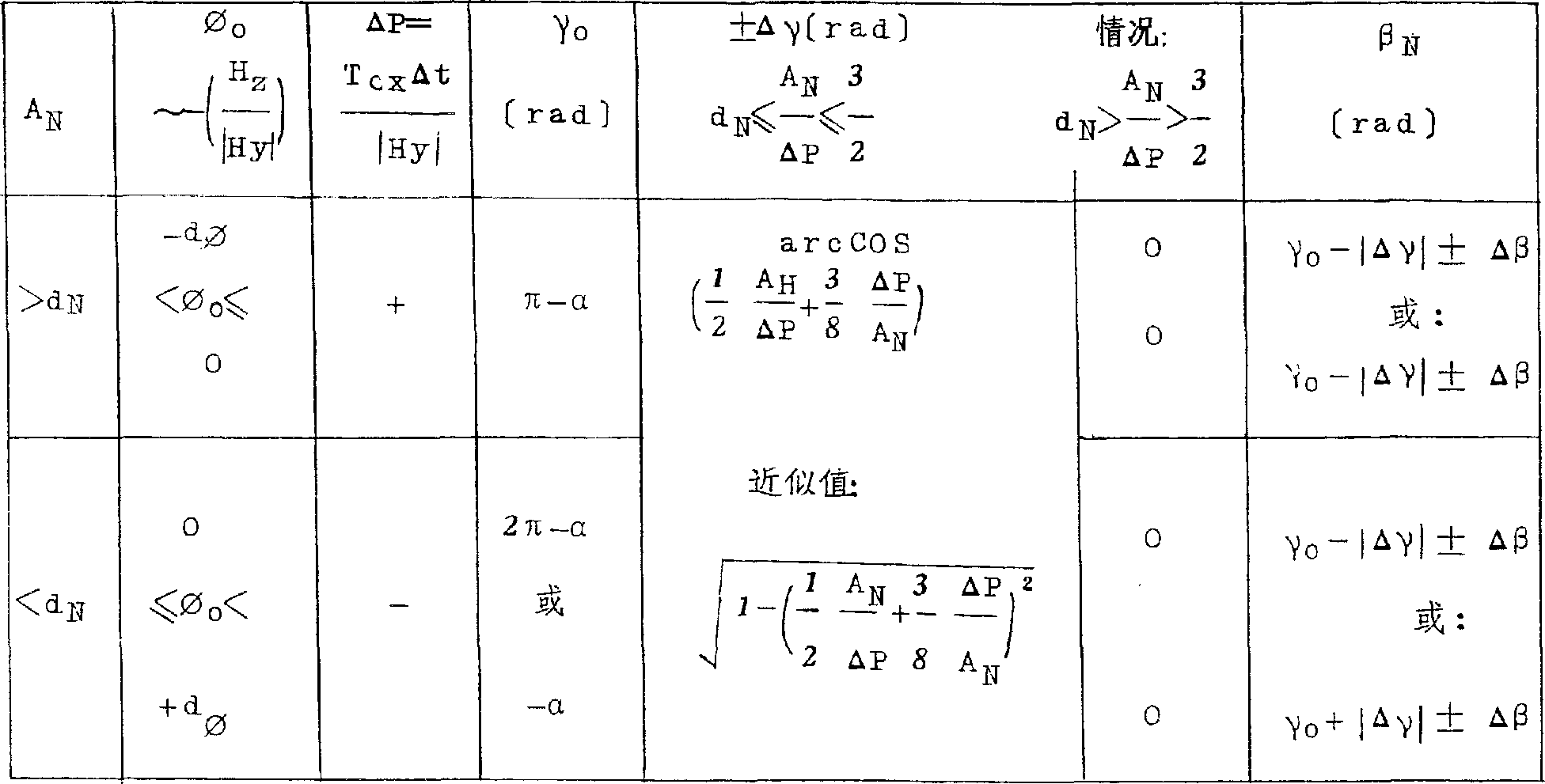 Table 2a: the action condition that in a pulse/nutation period, is used to suppress nutating
 Table 1b: for each nutation period with 2 pulse (Δ P
1, Δ P
2) time action condition (β
N1, β
N2) (rotation adjusting+inhibition nutating)
γ
01=π-α γ
02=(2 π)-α=γ
01+ π shows 2b: the action condition (β that suppresses nutating for each nutation period with 2 pulses (around the X-axle)
N1, β
N2)
Table 1b: for each nutation period with 2 pulse (Δ P
1, Δ P
2) time action condition (β
N1, β
N2) (rotation adjusting+inhibition nutating)
γ
01=π-α γ
02=(2 π)-α=γ
01+ π shows 2b: the action condition (β that suppresses nutating for each nutation period with 2 pulses (around the X-axle)
N1, β
N2)
 γ
02=pi/2=γ
02+ pi/2 γ
04=3 pi/2s=γ
02+ π=γ
01+ pi/2 table 2c: the action condition (β that suppresses nutating for each nutation period with 2 pulses (around the Z-axle)
N3, β
N4) action condition (according to WO89/02622) the nutating amplitude A of the best rotation of annex and nutating adjusting
NCireular frequency by estimation
Nutation frequency ω
NWith transverse axis rotor inertia I
X, I
ZPressing the following formula formula obtains:
The relational expression at phase angle is:
γ
02=pi/2=γ
02+ pi/2 γ
04=3 pi/2s=γ
02+ π=γ
01+ pi/2 table 2c: the action condition (β that suppresses nutating for each nutation period with 2 pulses (around the Z-axle)
N3, β
N4) action condition (according to WO89/02622) the nutating amplitude A of the best rotation of annex and nutating adjusting
NCireular frequency by estimation
Nutation frequency ω
NWith transverse axis rotor inertia I
X, I
ZPressing the following formula formula obtains:
The relational expression at phase angle is:
 This relational expression is represented, when nutation movement also reaches maxim (+A around first lateral axis (X-axle) with Z axle quadrature around second lateral axis (Z-axle) simultaneously by zero
N) time, the nutating phase place is by zero.Signal (Δ t according to given regulation formation
CX, A
N, β
N) interconnect as follows in modulator and amplitude/phase converter output end, promptly modulator is judged the essentiality of regulating action, symbol and time length, and the output signal of amplitude/phase conv is judged moment point (the Δ T of the regulating action in nutation period
CX).Whether stipulated one of each nutation period or two regulating actions are distinguished two kinds of situations according to the pulse repetition frequency of modulator.
This relational expression is represented, when nutation movement also reaches maxim (+A around first lateral axis (X-axle) with Z axle quadrature around second lateral axis (Z-axle) simultaneously by zero
N) time, the nutating phase place is by zero.Signal (Δ t according to given regulation formation
CX, A
N, β
N) interconnect as follows in modulator and amplitude/phase converter output end, promptly modulator is judged the essentiality of regulating action, symbol and time length, and the output signal of amplitude/phase conv is judged moment point (the Δ T of the regulating action in nutation period
CX).Whether stipulated one of each nutation period or two regulating actions are distinguished two kinds of situations according to the pulse repetition frequency of modulator.
In first kind of situation, regulating action (by modulator regulation time length and symbol) is at nutational angle β
N, 0≤β
NCarry out in≤360 ° the following ranges:
γ
0+ Δ γ-Δ β≤β
N(t)≤γ
0+ Δ γ+Δ β (B-3) needs only:
Promptly when the nutating amplitude A that obtains continuously
NInstantaneous value greater than half, and during less than one and half nutating half cones, this nutating half cone produces minimum pulse Δ P
X, here:
Perhaps use method of approximation:
Has fixed value γ
0, Δ β, best
Radian
γ
0=π-α is for positive control
γ
0=2 π-α is for down regulation (B-8)
On the contrary, if the nutating amplitude A
N(equation B-1) is greater than or less than the given limit, so, and should be at nutational angle β
N(t): 0≤β
NThe following ranges of≤2 π realizes regulating action:
γ
0-Δ β≤β
N(t)≤γ
0+ Δ β (B-8) is wherein:
γ=γ
0The optimum phase angle of regulating action in nutating vibration of+Δ γ-be illustrated in.T
Cx---the moment level Δ t of expression regulating action
Cx---expression is by time length α of the regulating action of modulator instruction---inclination stagger angle of expression power element
Other amount (Δ P
x, γ
0, Δ γ) determine by the equation (B-5, B-7, B-8) of this tittle of explanation.
When have two regulating actions each nutation period, when
γ
0-Δ γ
1-Δ β≤β
N1(t)≤γ
0-Δ γ
1During+Δ β (B-3), carry out first regulating action, as long as:
A
N≤ 2 Δ P
x(B-9) and at this moment:
When
γ
0-Δ β≤β
N2(t)≤γ
0During+Δ β (B-11), carry out second regulating action.
Requirement unconditionally for this reason, be shorter than half nutation period (T
N) time in determine the nutating amplitude A
NWith the nutating phase beta
NIf, for example, when at a slow speed data handing can not guarantee this point because of high nutation frequency and/or in electronic machine, so, according to the condition of second pulse of equation B-11 with the replacement of pressing equation (B-12):
Δ β
N2(t)=2 Δ γ+2n π (B-12) wherein, n=0,1,2
β
N2>0 is opposite, if A
N>2 Δ P
x(B-13) can put Δ γ so
1Two conditions of=0 (B-14) (B-3) and (B-11) be co-conversion mutually.
Claims (3)
1. be used for three axially stable, the attitude control method of rotation spacecraft relates to and keeps hand of rotation and at least one dead zone element limits nutating amplitude of application in the inert space, it is characterized in that, surpassing given startup boundary (+d by means of the dead zone element (204,209) that separates
φ, d
N) aspect not only constantly checks the deviation of hand of rotation from specified orientation, and constantly check the nutating amplitude, and then, when hand of rotation is positioned at by starting boundary (± d
φ) given, in the time of in the allowed band, for the purpose that reduces nutating starts regulating action separately.
2. be used for relate to can be given the regulation attitude aspect three attitude control methods axially stable, the rotation spacecraft, this spacecraft has been equipped power element, be used to produce around two with the rotation axis quadrature, and the adjusting moment of the lateral axis of mutual quadrature, in the method, by means of at least one attitude sensor obtain representative in two lateral axiss, with respect to the angular deviation signal of the angular deviation that requires attitude, form the component of signal (Φ of first expression spacecraft orbit motion by this angular deviation signal
O) and second component of signal (Φ that represents the spacecraft nutation movement
N), use the incoming signal that first component of signal obtains the first dead zone element (204), use second component of signal and obtain to represent nutating amplitude (A
N) and nutating phase place (β
N) signal, the output signal of these signals and the first dead zone element is defeated by the nutating regulating control (205) of determining to be started by power element the moment of regulating action, it is characterized in that, represents nutating amplitude (A
N) signal also be defeated by the second dead zone element (209), select the startup boundary (Φ of the second dead zone element according to the nutating amplitude of high permission that can be given
N), the output signal of the second dead zone element is similarly nutating regulating control (205) and receives, and this be in to attached as the essentiality of regulating action consider this output signal when decisioing making.
3. be used for relate to can be given the regulation attitude aspect three attitude regulating mechanisms axially stable, the rotation spacecraft, this spacecraft has at least one attitude sensor (101), be used for measuring around two with rotation axis (Y) lateral axis (X quadrature and mutually orthogonal, Z) in one, with respect to the angular deviation of regulation attitude, power element (211) is still arranged, be used to produce adjusting moment, still have one to receive the angular deviation signal (∈ that describes angular deviation around two lateral axiss
φ) and therefore represent spacecraft orbit is moved, the generation first component of signal (Φ
O) regulating control network (201), one is used for from angular deviation signal (∈
φ) obtain to represent the secondary signal component (Φ of spacecraft nutation movement
N) first device (202), one connect after having the first dead zone element (204), receive the first component of signal (Φ
O) rotary actuator (203), one is used for from secondary signal component (Φ
N) obtain to represent nutating amplitude (A
N) and nutating phase place (β
N) second device (207,208) of signal, and be connected to second device and the nutating regulating control (205) of the first dead zone element (204) after one, be used for determining to start the moment of regulating moment, it is characterized in that having second reception and represent nutating amplitude (A
N) dead zone element (209) signal, that an output signal sent to the nutating regulating control.
Applications Claiming Priority (2)
| Application Number | Priority Date | Filing Date | Title |
|---|---|---|---|
| DEP4129628.1 | 1991-09-06 | ||
| DE4129628A DE4129628A1 (en) | 1991-09-06 | 1991-09-06 | METHOD AND DEVICE FOR CONTROLLING THE POSITION OF A THREE-AXIS-STABILIZED SPIRAL VEHICLE |
Publications (2)
| Publication Number | Publication Date |
|---|---|
| CN1074187A CN1074187A (en) | 1993-07-14 |
| CN1039303C true CN1039303C (en) | 1998-07-29 |
Family
ID=6439990
Family Applications (1)
| Application Number | Title | Priority Date | Filing Date |
|---|---|---|---|
| CN92111579A Expired - Fee Related CN1039303C (en) | 1991-09-06 | 1992-09-05 | Method and device for regulating posture of triaxially stable revolving spacecraft |
Country Status (7)
| Country | Link |
|---|---|
| US (1) | US5597143A (en) |
| EP (1) | EP0602132B1 (en) |
| JP (1) | JP2637287B2 (en) |
| CN (1) | CN1039303C (en) |
| CA (1) | CA2117094A1 (en) |
| DE (2) | DE4129628A1 (en) |
| WO (1) | WO1993004924A1 (en) |
Families Citing this family (16)
| Publication number | Priority date | Publication date | Assignee | Title |
|---|---|---|---|---|
| FR2714357B1 (en) * | 1993-12-27 | 1996-03-22 | Aerospatiale | Method for minimizing, damping or compensating for disturbances on a satellite stabilized by autorotation. |
| US6439509B1 (en) * | 1995-07-03 | 2002-08-27 | Space Systems/Loral, Inc. | Pre-bias scheme for roll momentum unloads on pitch momentum bias/yaw reaction wheel spacecraft |
| US6241194B1 (en) * | 1999-06-28 | 2001-06-05 | Honeywell International Inc. | Momentum position control |
| US6347262B1 (en) * | 2000-01-05 | 2002-02-12 | Hughes Electronics Corporation | Minimum fuel attitude and nutation controller for spinning spacecraft |
| US6292722B1 (en) * | 2000-02-24 | 2001-09-18 | Space Systems/Loral, Inc. | Magnetic torquer control with thruster augmentation |
| JP4463287B2 (en) | 2007-02-07 | 2010-05-19 | Nec東芝スペースシステム株式会社 | Posture change control method, posture change control system, posture change control program, and program recording medium |
| CN100459376C (en) * | 2007-03-13 | 2009-02-04 | 王晨光 | Novel high power DC generator |
| CN100452633C (en) * | 2007-04-26 | 2009-01-14 | 北京航空航天大学 | A magnetic levitation counteractive flying wheel |
| US8620496B2 (en) * | 2008-07-23 | 2013-12-31 | The Boeing Company | Systems and method of controlling a spacecraft using attitude sensors |
| CN102053622B (en) * | 2010-10-26 | 2012-12-12 | 南京航空航天大学 | Method for controlling procession of bias momentum micro-satellite |
| CN102411304B (en) * | 2011-12-15 | 2013-03-20 | 北京航空航天大学 | Optimization method of spacecraft small-angle attitude maneuver control parameters |
| CN103264776B (en) * | 2013-05-30 | 2015-04-22 | 中国空间技术研究院 | Control system working mode setting and switching method based on information fusion |
| US9638502B1 (en) * | 2014-08-18 | 2017-05-02 | Rockwell Collins, Inc. | Pulse error correction for spinning vehicles |
| CN105912013A (en) * | 2016-07-04 | 2016-08-31 | 上海航天控制技术研究所 | Model-free self-adaptive control method for attitude of assembled spacecraft |
| US11174046B2 (en) * | 2019-02-26 | 2021-11-16 | Larry D. Sinclair | System and method for rotating mass attitude control |
| CN111258326B (en) * | 2020-02-27 | 2021-04-23 | 中国科学院自动化研究所 | Roll stability control method and system of bionic robotic fish based on reaction wheel |
Citations (3)
| Publication number | Priority date | Publication date | Assignee | Title |
|---|---|---|---|---|
| US3984071A (en) * | 1974-08-29 | 1976-10-05 | Trw Inc. | Satellite nutation attenuation apparatus |
| US4288051A (en) * | 1976-09-18 | 1981-09-08 | Messerschmitt-Bolkow-Blohm Gesellschaft Mit Beschrankter Haftung | Method and apparatus for controlling a satellite |
| WO1989002622A1 (en) * | 1987-09-16 | 1989-03-23 | Messerschmitt-Bölkow-Blohm Gesellschaft Mit Beschr | Device for regulating a set value and/or for stabilizing freely moving objects with stored spin |
Family Cites Families (9)
| Publication number | Priority date | Publication date | Assignee | Title |
|---|---|---|---|---|
| US3937423A (en) * | 1974-01-25 | 1976-02-10 | Hughes Aircraft Company | Nutation and roll error angle correction means |
| US4114841A (en) * | 1977-02-22 | 1978-09-19 | Rca Corporation | Magnetic torquing system for changing the spin rate of an orbiting satellite |
| DE2732201C2 (en) * | 1977-07-16 | 1983-01-13 | Messerschmitt-Bölkow-Blohm GmbH, 8000 München | Regulator for the attitude stabilization of a satellite |
| FR2447320A1 (en) * | 1979-01-23 | 1980-08-22 | Matra | IMPROVEMENTS TO ACTIVE NUTATION DAMPING METHODS AND DEVICES FOR SPATIAL VEHICLE |
| US4424948A (en) * | 1981-01-22 | 1984-01-10 | Rca Corporation | Magnetically torqued nutation damping |
| US4504032A (en) * | 1982-03-10 | 1985-03-12 | Rca Corporation | Control of nutation in a spacecraft |
| US4537375A (en) * | 1983-04-21 | 1985-08-27 | Ford Aerospace & Communications Corporation | Method and apparatus for thruster transient control |
| US4916622A (en) * | 1988-06-16 | 1990-04-10 | General Electric Company | Attitude control system |
| US5098041A (en) * | 1990-06-07 | 1992-03-24 | Hughes Aircraft Company | Attitude control system for momentum-biased spacecraft |
-
1991
- 1991-09-06 DE DE4129628A patent/DE4129628A1/en not_active Withdrawn
-
1992
- 1992-09-04 CA CA002117094A patent/CA2117094A1/en not_active Abandoned
- 1992-09-04 EP EP92918874A patent/EP0602132B1/en not_active Expired - Lifetime
- 1992-09-04 DE DE59202173T patent/DE59202173D1/en not_active Expired - Fee Related
- 1992-09-04 WO PCT/EP1992/002050 patent/WO1993004924A1/en active IP Right Grant
- 1992-09-04 JP JP5504963A patent/JP2637287B2/en not_active Expired - Fee Related
- 1992-09-05 CN CN92111579A patent/CN1039303C/en not_active Expired - Fee Related
-
1993
- 1993-09-04 US US08/204,325 patent/US5597143A/en not_active Expired - Lifetime
Patent Citations (3)
| Publication number | Priority date | Publication date | Assignee | Title |
|---|---|---|---|---|
| US3984071A (en) * | 1974-08-29 | 1976-10-05 | Trw Inc. | Satellite nutation attenuation apparatus |
| US4288051A (en) * | 1976-09-18 | 1981-09-08 | Messerschmitt-Bolkow-Blohm Gesellschaft Mit Beschrankter Haftung | Method and apparatus for controlling a satellite |
| WO1989002622A1 (en) * | 1987-09-16 | 1989-03-23 | Messerschmitt-Bölkow-Blohm Gesellschaft Mit Beschr | Device for regulating a set value and/or for stabilizing freely moving objects with stored spin |
Also Published As
| Publication number | Publication date |
|---|---|
| JP2637287B2 (en) | 1997-08-06 |
| WO1993004924A1 (en) | 1993-03-18 |
| CN1074187A (en) | 1993-07-14 |
| DE4129628A1 (en) | 1993-03-18 |
| EP0602132A1 (en) | 1994-06-22 |
| JPH06510501A (en) | 1994-11-24 |
| CA2117094A1 (en) | 1993-03-18 |
| US5597143A (en) | 1997-01-28 |
| DE59202173D1 (en) | 1995-06-14 |
| EP0602132B1 (en) | 1995-05-10 |
Similar Documents
| Publication | Publication Date | Title |
|---|---|---|
| CN1039303C (en) | Method and device for regulating posture of triaxially stable revolving spacecraft | |
| US7795568B2 (en) | Solar tracking for terrestrial solar arrays | |
| US7298342B2 (en) | Antenna positioner system | |
| US5751078A (en) | Reactionless, momentum compensated payload positioner | |
| EP0712781A1 (en) | Spacecraft energy storage, attitude steering and momentum management system | |
| CN1105422A (en) | Earth/Gyro Power Converter | |
| CN1174982A (en) | Dynamic bais for controlling mavar orbital deviation | |
| US4843294A (en) | Solar array stepping to minimize array excitation | |
| US5822116A (en) | High-accuracy rotation control device, in particular for telescopes | |
| EP0520165B1 (en) | Momentum wheel platform steering system and method | |
| CN1025995C (en) | Attitude pointing error correction system and method for geosynchronous satellites | |
| US7343228B2 (en) | Transient cancellation technique for spacecraft solar wing stepping | |
| US7364120B2 (en) | Quantized control-moment gyroscope array | |
| CN116119037A (en) | Satellite in-orbit micro-vibration intelligent suppression system | |
| CN106184820A (en) | A kind of combination drives many moment leaving momentum wheel and control method thereof | |
| US9617015B2 (en) | Method of commanding an attitude control system and attitude control system of a space vehicle | |
| CN113110612B (en) | Double-shaft solar cell array driving device and motion planning method thereof | |
| US6917861B2 (en) | Method and apparatus for stepping space craft mechanisms at low disturbance rates | |
| CN110562494B (en) | Satellite thrust eccentric moment control device and method | |
| CN117074798B (en) | Satellite antenna test turntable applied to navigation function aircraft | |
| CN112650260B (en) | Solar sailboard variable-speed driving method under inclined orbit satellite yaw guidance | |
| US20040122568A1 (en) | System for controlling the attitude of a geostationary satellite | |
| EP0796786A1 (en) | Method and device for rapid actuation of a payload on board a space platform | |
| JP3536066B2 (en) | Artificial satellite | |
| CN109131942A (en) | A kind of method for the rotary body progress despun control to satellite and corresponding racemization device |
Legal Events
| Date | Code | Title | Description |
|---|---|---|---|
| C06 | Publication | ||
| PB01 | Publication | ||
| C10 | Entry into substantive examination | ||
| SE01 | Entry into force of request for substantive examination | ||
| C14 | Grant of patent or utility model | ||
| GR01 | Patent grant | ||
| C15 | Extension of patent right duration from 15 to 20 years for appl. with date before 31.12.1992 and still valid on 11.12.2001 (patent law change 1993) | ||
| OR01 | Other related matters | ||
| C19 | Lapse of patent right due to non-payment of the annual fee | ||
| CF01 | Termination of patent right due to non-payment of annual fee |