CN103887600A - Wireless coverage antenna unit, antenna assembly and multi-antenna assembly - Google Patents
Wireless coverage antenna unit, antenna assembly and multi-antenna assembly Download PDFInfo
- Publication number
- CN103887600A CN103887600A CN201210554922.8A CN201210554922A CN103887600A CN 103887600 A CN103887600 A CN 103887600A CN 201210554922 A CN201210554922 A CN 201210554922A CN 103887600 A CN103887600 A CN 103887600A
- Authority
- CN
- China
- Prior art keywords
- antenna
- antenna unit
- wireless coverage
- unit according
- coverage
- Prior art date
- Legal status (The legal status is an assumption and is not a legal conclusion. Google has not performed a legal analysis and makes no representation as to the accuracy of the status listed.)
- Granted
Links
Images


Landscapes
- Aerials With Secondary Devices (AREA)
Abstract
本发明涉及一种无线覆盖天线单元,包括基板;设置于基板上辐射电磁波的振子;以及设置于基板上、根据自身结构、尺寸及其与振子之间的距离使所述天线单元在预设频段内辐射的波束宽度小于180度,并且对所述天线单元在另一同频天线单元覆盖范围的辐射强度进行抑制的引向器。本发明提供的天线单元具有良好的方向性,可以在预设频段内实现窄波束无线覆盖,避免对不需要覆盖区域造成电磁辐射,并且可提高覆盖区域的信号强度。
The invention relates to a wireless coverage antenna unit, comprising a substrate; a vibrator arranged on the substrate to radiate electromagnetic waves; The beam width of the internal radiation is less than 180 degrees, and the director suppresses the radiation intensity of the antenna unit in the coverage area of another same-frequency antenna unit. The antenna unit provided by the present invention has good directivity, can realize narrow-beam wireless coverage in a preset frequency band, avoids electromagnetic radiation to unnecessary coverage areas, and can improve signal strength in coverage areas.
Description
技术领域technical field
本发明涉及无线通讯器件领域,更具体地说,涉及一种无线覆盖天线单元、天线组件及多天线组件。The invention relates to the field of wireless communication devices, more specifically, to a wireless coverage antenna unit, an antenna assembly and a multi-antenna assembly.
背景技术Background technique
无线局域网(WLAN)利用无线技术在空中传输数据、话音和视频信号。作为传统布线网络的一种替代方案或延伸,无线局域网使用户可以随时随地获取信息,提高了办事效率。Wi-Fi是WLAN无线设备提供的无线空中接口,方便用户打长途电话、浏览网页、收发电子邮件、音乐下载、数码照片传递等。Wi-Fi在掌上设备上应用越来越广泛,尤其成为目前移动通信业界的潮流。A wireless local area network (WLAN) uses wireless technology to transmit data, voice and video signals over the air. As an alternative or extension of the traditional wiring network, wireless local area network enables users to obtain information anytime and anywhere, improving work efficiency. Wi-Fi is a wireless air interface provided by WLAN wireless devices, which is convenient for users to make long-distance calls, browse the web, send and receive emails, download music, and transfer digital photos. Wi-Fi is more and more widely used on handheld devices, especially becoming a trend in the current mobile communication industry.
现有技术中,Wi-Fi采用的天线一般位于在室外,覆盖面比较广,对不需要Wi-Fi覆盖的区域会造成辐射,如何在需要无线覆盖的室内位于小型化Wi-Fi天线,并且增强Wi-Fi信号,是本发明所要解决的问题。In the prior art, the antennas used by Wi-Fi are generally located outdoors, with relatively wide coverage, which will cause radiation in areas that do not require Wi-Fi coverage. How to locate a miniaturized Wi-Fi antenna indoors where wireless coverage is required, and enhance the Wi-Fi signal is the problem to be solved by the present invention.
发明内容Contents of the invention
针对上述技术问题,本发明提供一种基于窄波束的小型化的无线覆盖天线单元、天线组件及多天线组件。In view of the above technical problems, the present invention provides a miniaturized wireless coverage antenna unit, an antenna assembly and a multi-antenna assembly based on a narrow beam.
一种无线覆盖天线单元,包括基板;设置于基板上辐射电磁波的振子;以及设置于基板上、根据自身结构、尺寸及其与振子之间的距离使所述天线单元在预设频段内辐射的波束宽度小于180度,并且对所述天线单元在另一同频天线单元覆盖范围的辐射强度进行抑制的引向器。A wireless coverage antenna unit, comprising a substrate; a vibrator arranged on the substrate to radiate electromagnetic waves; and a vibrator arranged on the substrate to make the antenna unit radiate in a preset frequency band according to its own structure, size and distance from the vibrator The beam width is less than 180 degrees, and the director suppresses the radiation intensity of the antenna unit in the coverage area of another same-frequency antenna unit.
可选的,所述天线单元在另一同频天线单元覆盖范围的辐射强度对应的抑制度≤-(y+x0)+20*log10(R2/R1)dB;其中:y代表将所述另一同频天线单元辐射的电磁波作为噪声处理的信噪比标准;x0代表所述天线单元在地面覆盖区域增益下降的最大值;R1代表所述天线单元架设位置与增益下降x0对应某点之间的距离;R2代表另一同频天线单元覆盖范围增益下降最小值对应点与所述天线单元架设位置之间的距离。Optionally, the suppression degree corresponding to the radiation intensity of the antenna unit in the coverage area of another same-frequency antenna unit is ≤-(y+x0)+20*log10(R2/R1)dB; where: y represents that the other same-frequency antenna unit The electromagnetic wave radiated by the high-frequency antenna unit is used as the signal-to-noise ratio standard for noise processing; x0 represents the maximum value of the gain drop of the antenna unit in the ground coverage area; R1 represents the distance between the erection position of the antenna unit and a point corresponding to the gain drop x0 ; R2 represents the distance between the point corresponding to the minimum value of the coverage gain drop of another co-frequency antenna unit and the installation position of the antenna unit.
可选的,所述天线单元的抑制度大于-15dB。Optionally, the suppression degree of the antenna unit is greater than -15dB.
可选的,所述天线单元的抑制度大于-20dB。Optionally, the suppression degree of the antenna unit is greater than -20dB.
可选的,所述天线单元的抑制度大于-10dB。Optionally, the suppression degree of the antenna unit is greater than -10dB.
可选的,所述天线单元在另一同频天线单元覆盖范围的辐射强度进行抑制的抑制角度△θ=θ2-θ1,其中:θ1、θ2分别代表所述天线单元在预设高度的垂直距离与所述另一同频天线单元覆盖区域边缘上天线增益下降最小、最大值对应点之间的夹角。Optionally, the suppression angle Δθ=θ 2 -θ 1 at which the radiation intensity of the antenna unit is suppressed in the coverage area of another same-frequency antenna unit, wherein: θ1 and θ2 respectively represent the vertical angle of the antenna unit at a preset height The angle between the distance and the point corresponding to the minimum and maximum drop in antenna gain on the edge of the coverage area of the another same-frequency antenna unit.
可选的,所述预设高度小于70m。Optionally, the preset height is less than 70m.
可选的,所述预设高度小于31m。Optionally, the preset height is less than 31m.
可选的,所述预设高度小于25m。Optionally, the preset height is less than 25m.
可选的,所述预设高度小于5m。Optionally, the preset height is less than 5m.
可选的,所述天线单元的覆盖范围是圆形、椭圆形、或者不规则形状。Optionally, the coverage area of the antenna unit is circular, elliptical, or irregular.
可选的,所述另一同频天线单元的覆盖范围是圆形、椭圆形、或者不规则形状。Optionally, the coverage of the other same-frequency antenna unit is circular, elliptical, or irregular.
可选的,所述天线单元的覆盖范围与所述另一同频天线单元覆盖范围大小相同或者不同。Optionally, the coverage area of the antenna unit is the same as or different from the coverage area of the other same-frequency antenna unit.
可选的,所述天线单元的覆盖范围与所述另一同频天线单元覆盖范围形状相同或者不同。Optionally, the coverage area of the antenna unit is the same or different from the coverage area of the other same-frequency antenna unit.
可选的,所述预设频段是802.11WLAN标准频段。Optionally, the preset frequency band is an 802.11 WLAN standard frequency band.
可选的,所述预设频段是2.484GHz-3.7GHz。Optionally, the preset frequency band is 2.484GHz-3.7GHz.
可选的,所述预设频段是2.4GHz-2.5GHz。Optionally, the preset frequency band is 2.4GHz-2.5GHz.
可选的,所述预设频段是3.65GHz-3.7GHz。Optionally, the preset frequency band is 3.65GHz-3.7GHz.
可选的,所述预设频段是4.9GHz-5.9GHz。Optionally, the preset frequency band is 4.9GHz-5.9GHz.
可选的,所述预设频段是5.15GHz-5.35GHz。Optionally, the preset frequency band is 5.15GHz-5.35GHz.
可选的,所述预设频段是5.725GHz-5.85GHz。Optionally, the preset frequency band is 5.725GHz-5.85GHz.
可选的,所述振子和引向器均为导体。Optionally, both the vibrator and the director are conductors.
可选的,所述导体是金属线或者金属片。Optionally, the conductor is a metal wire or a metal sheet.
可选的,所述引向器有至少2个且相互平行。Optionally, there are at least two directors parallel to each other.
可选的,至少2个所述引向器的中心在同一直线上且所述直线垂直于所述引向器。Optionally, the centers of at least two of the directors are on the same straight line and the straight line is perpendicular to the directors.
可选的,还包括与振子连接的馈线。Optionally, a feeder connected to the vibrator is also included.
可选的,所述振子包括共线的两条导体线,且分别与所述引向器的导体线平行。Optionally, the vibrator includes two colinear conductor lines, which are respectively parallel to the conductor lines of the director.
可选的,所述振子的总长度大于每个所述引向器的长度。Optionally, the total length of the vibrator is greater than the length of each director.
本发明还涉及一种无线覆盖天线组件,包括用于反射电磁波的反射面和位于所述反射面一侧的天线组,所述天线组包括至少一个上述的无线覆盖天线单元,所述反射面、每个所述天线单元的引向器分别位于相应的天线单元的振子两侧。The present invention also relates to a wireless coverage antenna assembly, comprising a reflective surface for reflecting electromagnetic waves and an antenna group located on one side of the reflective surface, the antenna group includes at least one wireless coverage antenna unit described above, the reflective surface, The director of each antenna unit is respectively located on both sides of the vibrator of the corresponding antenna unit.
可选的,所述天线组包括三个相同的天线单元,每个所述天线单元的基板垂直于所述反射面,且三个所述天线单元互成120度、以同一直线为延长相交线、且到所述延长相交线的距离均相等地设置。Optionally, the antenna group includes three identical antenna units, the substrate of each antenna unit is perpendicular to the reflecting surface, and the three antenna units are 120 degrees to each other, and the same straight line is used as an extended intersection line , and the distances to the extended intersecting lines are set equally.
可选的,所述天线组包括三个相同的天线单元,每个所述天线单元的基板垂直于所述反射面,三个天线单元互成60度、且三个天线单元的基板沿各自表面方向延长后相交构成正三角形。Optionally, the antenna group includes three identical antenna units, the substrates of each antenna unit are perpendicular to the reflecting surface, the three antenna units are 60 degrees to each other, and the substrates of the three antenna units are along the respective surfaces After the direction is extended, they intersect to form an equilateral triangle.
本发明还涉及一种无线覆盖多天线组件,包括用于反射电磁波的反射面和位于所述反射面一侧的至少两个天线组,不同天线组所使用的电磁波频率不同,每个天线组包括至少一个上述的天线单元,所述反射面、每个所述天线单元的引向器分别位于相应的天线单元的振子两侧。The present invention also relates to a wireless coverage multi-antenna assembly, comprising a reflective surface for reflecting electromagnetic waves and at least two antenna groups located on one side of the reflective surface, different antenna groups use different frequencies of electromagnetic waves, and each antenna group includes For at least one above-mentioned antenna unit, the reflective surface and the director of each antenna unit are respectively located on both sides of the vibrator of the corresponding antenna unit.
可选的,所述多天线组件包括第一天线组和第二天线组,第一天线组的天线单元的振子尺寸大于第二天线组的天线单元的振子尺寸。Optionally, the multi-antenna assembly includes a first antenna group and a second antenna group, and the dipole size of the antenna units of the first antenna group is larger than the dipole size of the antenna units of the second antenna group.
可选的,所述第一天线组和第二天线组分别包括三个相同的天线单元,每个所述天线单元的基板垂直于所述反射面,且所述第一天线组的三个天线单元互成120度、以同一直线为延长相交线、且到所述延长相交线的距离均相等,所述第二天线组的三个天线单元互成60度、且三个天线单元的基板沿表面方向延长后相交构成正三角形。Optionally, the first antenna group and the second antenna group respectively include three identical antenna units, the substrate of each antenna unit is perpendicular to the reflecting surface, and the three antennas of the first antenna group The units are 120 degrees to each other, the same straight line is used as the extended intersection line, and the distances to the extended intersection line are equal, the three antenna units of the second antenna group are 60 degrees to each other, and the substrates of the three antenna units are along the The surface directions are extended and intersect to form an equilateral triangle.
可选的,所述第二天线组的三个天线单元依次位于所述第一天线组的三个天线单元的三个相邻间隔中。Optionally, the three antenna units of the second antenna group are sequentially located in three adjacent intervals of the three antenna units of the first antenna group.
相对于现有技术,本发明的有益效果在于:在预设的频段内,依据八木天线原理设计的天线单元、天线组件、多天线组件具有良好的方向性,波束窄,避免对不需要覆盖区域造成电磁辐射,并且可提高覆盖区域的信号强度。Compared with the prior art, the beneficial effect of the present invention is that: in the preset frequency band, the antenna unit, antenna assembly, and multi-antenna assembly designed according to the Yagi antenna principle have good directivity and narrow beams, avoiding unnecessary coverage areas Causes electromagnetic radiation and can increase signal strength in the coverage area.
附图说明Description of drawings
下面将结合附图及实施例对本发明作进一步说明:The present invention will be further described below in conjunction with accompanying drawing and embodiment:
图1为本发明的天线单元的结构示意图;Fig. 1 is the structural representation of antenna unit of the present invention;
图2a、2b为本发明实施例提供的天线单元辐射电磁波的示意图;2a and 2b are schematic diagrams of electromagnetic waves radiated by the antenna unit provided by the embodiment of the present invention;
图3为本发明实施例提供的天线单元增益衰减等效示意图;FIG. 3 is an equivalent schematic diagram of antenna unit gain attenuation provided by an embodiment of the present invention;
图4为具有图1所示天线单元的天线组件的结构示意图;FIG. 4 is a schematic structural diagram of an antenna assembly having the antenna unit shown in FIG. 1;
图5为具有至少两个天线组的多天线组件的结构示意图;5 is a schematic structural diagram of a multi-antenna assembly with at least two antenna groups;
图6为图5所示多天线组件的俯视图;FIG. 6 is a top view of the multi-antenna assembly shown in FIG. 5;
图7是图5所示多天线组件的第一天线组的天线单元的尺寸示意图;Fig. 7 is a schematic diagram of the dimensions of the antenna elements of the first antenna group of the multi-antenna assembly shown in Fig. 5;
图8为图5所示多天线组件的第二天线组的天线单元的尺寸示意图;FIG. 8 is a schematic diagram of the dimensions of the antenna elements of the second antenna group of the multi-antenna assembly shown in FIG. 5;
图9为图5、图6所示多天线组件的低频段电压驻波比仿真图;Fig. 9 is a low frequency VSWR simulation diagram of the multi-antenna assembly shown in Fig. 5 and Fig. 6;
图10为上述多天线组件在频率为2.45GHz时的方向图;FIG. 10 is a directional diagram of the above-mentioned multi-antenna assembly at a frequency of 2.45 GHz;
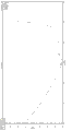
图11为图5、图6所示多天线组件的高频段电压驻波比仿真图;Fig. 11 is a simulation diagram of the high-frequency voltage standing wave ratio of the multi-antenna assembly shown in Fig. 5 and Fig. 6;
图12为上述多天线组件在频率为5.72GHz时的方向图。FIG. 12 is a directivity diagram of the above-mentioned multi-antenna assembly at a frequency of 5.72 GHz.
具体实施方式Detailed ways
现在详细参考附图中描述的实施例。为了全面理解本发明,在以下详细描述中提到了众多具体细节。但是本领域技术人员应该理解,本发明可以无需这些具体细节而实现。在其他实施方式中,不详细描述公知的方法、过程、组件和电路,以免不必要地使实施例模糊。Reference will now be made in detail to the embodiments depicted in the accompanying drawings. In the following detailed description, numerous specific details are set forth in order to provide a thorough understanding of the present invention. However, it will be understood by those skilled in the art that the present invention may be practiced without these specific details. In other embodiments, well-known methods, procedures, components and circuits have not been described in detail so as not to unnecessarily obscure the embodiments.
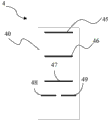
如图1所示,本发明的天线单元4包括基板40和附着在基板40上的振子和引向器。基板40采用FR4、F4b、铁氟龙、聚四氟乙烯等材料制成,或者其他现有天线所采用的基板材料。As shown in FIG. 1 , the
振子用于辐射电磁波,可以是金属线或者金属片,与馈线连接,包括两条导体线,分别为第一导体线48和第二导体线49,其中第一导体线48与同轴线馈线的外导体电连接,第二导体线49与同轴线馈线的芯线电连接。显然,第一导体线48、第二导体线49的位置可互换。The vibrator is used to radiate electromagnetic waves. It can be a metal wire or a metal sheet. It is connected to the feeder line and includes two conductor lines, which are the
如图1所示,第一导体线48和第二导体线49在同一条直线上,二者之间隔有一定间距。As shown in FIG. 1 , the
引向器用于根据自身结构、尺寸及其与振子之间的距离使天线单元4在802.11WLAN标准频段内辐射的波束宽度小于180度,例如调整引向器的长度在0.38-0.4波长范围,调整引向器与振子之间的距离,使天线单元的辐射的波束宽度在40-60度,一般情况下,引向器与振子之间的距离越长,波束宽度越窄。在具体的实施过程中,还可能需要考虑引向器的个数、以及引向器之间的间距对波束宽度的影响。其中,WLAN标准频段的可以是2.484GHz-3.7GHz、2.4GHz-2.5GHz、3.65GHz-3.7GHz、4.9GHz-5.9GHz、5.15GHz-5.35GHz、或者5.725GHz-5.85GHz中的任意一种频段。波束宽度范围可以是0-180度、130-160度、90-120度、40-60度、或者10-30度中的任意一个范围,优选40-60度,还可以是根据需要设置的小于180度的其他范围的窄波束。The director is used to make the beam width radiated by the
参见图2a、2b所示,本发明实施例提供了天线单元辐射电磁波的示意图。一天线单元在距离地面高度为h的A点向周围辐射电磁波,天线单元向在地面上的形成圆形、椭圆形、或者不规则形状的覆盖区域,如在G0点天线单元增益下降x1dB,在G1点天线单元增益下降x0dB(如3dB、5dB、或者10dB),图2a示出了x1=x0的情况,图2b示出了x1≠x0的情况。以图2a为例,假设G1点是位于A点的天线单元覆盖区域增益下降最小值对应的点,对应的波束宽度是θ0,假设G2、G3点分别是另一同频天线单元覆盖区域的增益下降最小、最大值对应的两点,且该另一同频天线单元在G2、G3点的增益分别下降-x1dB和-x2dB。根据高度h、A与G2点之间的距离可以计算出位于A点的天线单元在G2点的波束宽度是θ1;根据高度h、A点至G3点之间的距离是R3,可以计算出位于A点的天线单元在G3点的波束宽度是θ2。为了抑制位于A点的天线单元在G2、G3点之间造成同频干扰,需要抑制位于A点的天线单元在另一同频天线单元覆盖区域的辐射强度、以及G2、G3点之间的抑制角度△θ=θ2-θ1。Referring to Figs. 2a and 2b, the embodiment of the present invention provides schematic diagrams of antenna unit radiating electromagnetic waves. An antenna unit radiates electromagnetic waves to the surroundings at a point A at a height h from the ground, and the antenna unit forms a circular, elliptical, or irregular coverage area on the ground. For example, the gain of the antenna unit at G0 drops by x1dB, and at The gain of the antenna unit at point G1 is reduced by x0dB (such as 3dB, 5dB, or 10dB). Figure 2a shows the situation of x1=x0, and Figure 2b shows the situation of x1≠x0. Take Figure 2a as an example, assuming that point G1 is the point corresponding to the minimum gain drop in the coverage area of the antenna unit at point A, and the corresponding beamwidth is θ 0 , assuming that points G2 and G3 are the gain of the coverage area of another antenna unit with the same frequency The two points corresponding to the minimum and maximum values are dropped, and the gains of the other same-frequency antenna unit at points G2 and G3 are respectively reduced by -x1dB and -x2dB. According to the height h, the distance between A and G2, the beamwidth of the antenna unit at point A at G2 can be calculated as θ1; according to the height h, the distance between A and G3 is R3, and it can be calculated at The beam width of the antenna element at point A at point G3 is θ2. In order to suppress the antenna unit at point A from causing co-channel interference between points G2 and G3, it is necessary to suppress the radiation intensity of the antenna unit at point A in the coverage area of another co-frequency antenna unit and the suppression angle between points G2 and G3 △θ=θ 2 -θ 1 .
其中,所述天线单元与另一同频天线单元的覆盖范围是圆形、椭圆形、或者不规则形状。所述天线单元的覆盖范围与所述另一同频天线单元覆盖范围大小相同或者不同、覆盖范围形状相同或者不同。Wherein, the coverage area of the antenna unit and another same-frequency antenna unit is circular, elliptical, or irregular. The coverage area of the antenna unit is the same or different in size, and the coverage area shape is the same or different from that of the other same-frequency antenna unit.
将另一天线发射到该天线单元覆盖范围内的功率作为噪声进行处理,同时选ydB作为信噪比标准,x0代表所述天线单元在地面覆盖区域增益下降的最大值;则位于A点的天线单元在G2点增益下降x1dB<=-(y+x0)dB+20*log10(R2/R1)dB,可避免同频干扰。位于A点的天线单元在G3点增益下降x2dB<=-(y+x0)dB+20*log10(R3/R1)dB,可避免同频干扰。由于R3>R2,-x2dB<-x1dB,-x2dB属于小于-x1dB范围,因此位于A点的天线单元在另一同频天线单元覆盖区域的辐射强度(即抑制度)需满足:x1dB<=-(y+x0)dB+20*log10(R2/R1)dB。例如,天线单元悬挂高度是25米,半功率覆盖半径是18米,中心距离另一同频天线单元44.3米,则R1=30.8米,R2=50.9米;选20dB作为信噪比标准,x1dB<=-(y+x0)dB+y*log10(R2/R1)dB=-(20+3)dB+20*log10(50.9/30.8)dB=-20.3dB+4.36dB=-18.64dB,即在另一同频天线单元覆盖区域的抑制度<=-18.64dB。The power transmitted by another antenna into the coverage area of the antenna unit is treated as noise, and ydB is selected as the signal-to-noise ratio standard, and x0 represents the maximum value of the gain drop of the antenna unit in the ground coverage area; then the antenna located at point A The unit gains x1dB<=-(y+x0)dB+20*log10(R2/R1)dB at point G2 to avoid co-channel interference. The gain of the antenna unit at point A drops by x2dB<=-(y+x0)dB+20*log10(R3/R1)dB at point G3 to avoid co-channel interference. Since R3>R2, -x2dB<-x1dB, -x2dB belongs to the range less than -x1dB, so the radiation intensity (that is, the suppression degree) of the antenna unit located at point A in the coverage area of another antenna unit with the same frequency needs to meet: x1dB<=-( y+x0)dB+20*log10(R2/R1)dB. For example, the suspension height of the antenna unit is 25 meters, the half-power coverage radius is 18 meters, and the center is 44.3 meters away from another antenna unit with the same frequency, then R1=30.8 meters, R2=50.9 meters; choose 20dB as the signal-to-noise ratio standard, x1dB<= -(y+x0)dB+y*log10(R2/R1)dB=-(20+3)dB+20*log10(50.9/30.8)dB=-20.3dB+4.36dB=-18.64dB, that is, in another The suppression degree of the coverage area of the co-frequency antenna unit is <=-18.64dB.
天线单元的高度根据需求进行设定,通常情况下天线单元距离地面的高度小于70m,如北京鸟巢的高度是68.5m、最低高度是42m;深圳大运体育馆的高度是30.5m,有些建筑物的高度是25m,普通楼房的高度是2.5-3m。由于天线的位于高度不同,抑制角度与抑制度也会不同。如图3所示,当天线单元位于高度为h’的A’点时,天线单元的增益下降x0dB对应地面的位置是G点,根据高度h’、A’点与G点之间的距离可以计算出天线单元位于A’点的最小波束宽度θ0’,同理,可以计算出天线单元位于A’点的抑制度和抑制角度△θ’,通常情况下天线单元的抑制度大于-30dB、如大于-15dB、大于-20dB或者大于-10dB;抑制角度△θ’。The height of the antenna unit is set according to the requirements. Usually, the height of the antenna unit from the ground is less than 70m. For example, the height of the Beijing Bird’s Nest is 68.5m, and the minimum height is 42m; the height of the Shenzhen Universiade Stadium is 30.5m. The height is 25m, and the height of ordinary buildings is 2.5-3m. Due to the different heights of the antennas, the suppression angle and suppression degree will also be different. As shown in Figure 3, when the antenna unit is located at point A' with a height of h', the position of the ground where the gain of the antenna unit drops by x0dB is point G. According to the height h', the distance between point A' and point G can be Calculate the minimum beam width θ 0 ' of the antenna unit at point A'. Similarly, the suppression degree and suppression angle △θ' of the antenna unit at point A' can be calculated. Usually, the suppression degree of the antenna unit is greater than -30dB, Such as greater than -15dB, greater than -20dB or greater than -10dB; suppression angle Δθ'.
引向器可以只有一个,也可有多个,均为附着在基板40表面上的导体,当引向器有多个时,每个构成引向器的导体线相互平行,且均位于振子的同一侧,用来增强所处的振子一侧的电磁波强度,具体结构如图1所示。图1中的第三导体线45、第四导体线46、第五导体线47分别构成三个引向器,三个引向器相互平行地排布,并与构成振子的第一导体线48、第二导体线49平行。三个引向器的长度可以相同,也可以不同,为了电磁波引向效果更好,优选长度相等。另外,引向器的数量可以为三个,也可以为两个甚至一个,或者多于三个。通常,引向器多于五个后对电磁场的影响变化较小,为了节省空间和材料,优选引向器为三个。There can be only one or more directors, all of which are conductors attached to the surface of the
优选地,第三、第四、第五导体线45、46、47的中心点三点在一条直线线上,且该直线垂直三者中任意一条导体线。同时,振子所在的直线与上述任一条导体线平行且总长度大于上述任一条导体线,优选振子的中心与上述第一、第二、第三导体线的三个中心点在同一直线上。Preferably, the three central points of the third, fourth and
上述第一至第五导体线均采用导电材料制成,可以是金属线或者金属片,优选金属线,例如铜、铝、银等。具有这种结构的天线单元,在振子的另一侧装上反射器后,即可构成类似八木天线的结构。八木天线,又称八木-宇田天线,通常成“王”字形。振子(又称有源振子)居“王”字中间,与馈线相连。反射器位于振子一侧,起削弱该侧电磁波的作用,长度稍长于振子;引向器位于振子另一侧,稍短于振子,用于增强所在的这一侧的电磁波。The above-mentioned first to fifth conductor wires are all made of conductive materials, which may be metal wires or metal sheets, preferably metal wires, such as copper, aluminum, silver and the like. An antenna unit with this structure can form a structure similar to a Yagi antenna after installing a reflector on the other side of the vibrator. Yagi antenna, also known as Yagi-Uda antenna, is usually in the shape of "King". The vibrator (also known as active vibrator) is located in the middle of the word "Wang" and connected to the feeder. The reflector is located on one side of the vibrator, which weakens the electromagnetic wave on this side, and is slightly longer than the vibrator; the director is located on the other side of the vibrator, slightly shorter than the vibrator, and is used to enhance the electromagnetic wave on this side.
八木天线的优点是具有很好的方向性,通过本发明实施例提供的引向器,可以实现窄波束无线覆盖,避免对不需要覆盖区域造成电磁辐射,并且可提高覆盖区域的信号强度。The advantage of the Yagi antenna is that it has good directivity. Through the director provided by the embodiment of the present invention, narrow-beam wireless coverage can be realized, electromagnetic radiation is avoided in unnecessary coverage areas, and the signal strength of the coverage area can be improved.
本发明实施例还保护一种天线组件,如图4所示,包括反射面1和装在反射面1上的上述天线单元4。当天线单元4有多个,且这些天线单元4的工作频率在同一频率或同一频段时,它们构成一个天线组。The embodiment of the present invention also protects an antenna assembly, as shown in FIG. 4 , which includes a
反射面1用于反射任一天线单元4所使用的电磁波,使用的电磁波是指每个天线单元产生的电磁波或者每个天线单元接收的电磁波。在一些实施例中,反射介质面1可以采用铜或其它导电材料制成,且可以一个非平面的表面。可以理解地是,反射介质面1可以具有不连续的点,如加工成网状结构或者开设有孔等方式实现反射电波功能的介质表面,其中网状结构或者孔的尺寸大小小于所述多天线组件使用的电磁波波长的十分之一。The
反射面1和每个天线单元4上的引向器分别位于该天线单元4的振子两侧,整体构成了一个小型化的八木天线,其中反射面1即为上述反射器,振子的第一导体线48和第二导体线49构成上述有源振子,而第三、第四、第五导体线构成了三个引向器。而由于本发明的振子、引向器都采用了导体线而非金属管的形式,因此体积大大减小,结构更加紧凑,而天线也延续八木天线的良好方向性。同时,多个天线单元4共用一个反射面1,也能大大节省空间,减小天线的体积。The
当天线单元4有多个时,优选按照一定地规律来排布。图4所示的天线单元4有三个,且三个天线单元4完全相同,即具有相同的基板材料和基板尺寸,且振子和引向器的材料、尺寸、所在位置等也完全相同。那么这三个天线单元4的工作频率也基本相同,构成一个天线组,用于收发该工作频率的电磁波。When there are
图4中有三个相同的天线单元4,每个天线单元4的基板40垂直地安装在所质反射面1上,三个天线单元互成60度,且三个天线单元4的基板40沿各自表面方向延长后相交构成正三角形。Three
三个天线单元4还可以按照另一种方式来排布,即每个天线单元4的基板40同样垂直地安装在反射面1上,且三个天线单元4互成120度、以同一直线为任意两个基板表面的延长相交线,且三个天线单元4到该延长相交线的距离均相等。The three
当然,本发明的天线组件可以有三个天线单元,还可以只有一个、两个或者多于三个。天线单元也可以按照上述等分角度的方式来排布,也可按照阵列或随机方式来排布。Of course, the antenna assembly of the present invention may have three antenna elements, or only one, two or more than three. The antenna units may also be arranged in the above-mentioned manner of equally dividing the angles, or in an array or in a random manner.
当反射面1上的天线单元4有多个(本文的多个,都是指两个及两个以上),且多个天线单元4的工作频率不完全相同、或者说天线单元4不完全相同使得各自的工作频率不同时,将按照不同的工作频率来划分成不同的天线组。反射面1上具有多个天线组而构成的整体,称作多天线组件。When there are
如图5、图6所示,本实施例中的多天线组件具有两个天线组,每个天线组包括三个相同的天线单元,下文中将尺寸大的天线单元称为第一天线单元2,三个相同的第一天线单元2构成的天线组称之为第一天线组。尺寸小的天线单元称之为第二天线单元3,三个相同的第二天线单元3构成的天线组称之为第二天线组。由于第一天线单元2的尺寸大于第二天线单元3,因此,第一天线单元2与反射面1构成的天线的工作频率要低于第二天线单元与反射面1构成的天线。因此,本实施例的多天线组件属于双频天线。当然,这里影响工作频率的主要因素是振子的尺寸,因此,即使第一天线单元2和第二天线单元3的基板的尺寸都相同,只要第一天线单元2的振子尺寸大于第二天线单元3的振子,那么前者的工作频率通常都会低于后者。As shown in Figures 5 and 6, the multi-antenna assembly in this embodiment has two antenna groups, and each antenna group includes three identical antenna units, and the antenna unit with a large size is referred to as the
每个天线单元的基板都垂直于反射面1,且其安装使得该天线单元的引向器和所述反射面1位于该天线单元振子的两侧。The base plate of each antenna unit is perpendicular to the
如图6所示,三个第一天线单元2互成120度,并以同一直线为三个基板表面的延长相交线,且三个第一天线单元2到所述延长相交线的距离均相等。也可以理解为,以图6所示的俯视图来看,三个第一天线单元2以同一点为旋转中心,任一第一天线单元2以该旋转中心旋转120度后与另一第一天线单元2重合。As shown in Figure 6, the three
三个第二天线单元3按图4所示的方式排布,即两两互成60度、且三个第二天线单元3的基板沿表面方向延长后相交构成正三角形。且如图6所示,每两个第一天线单元2之间设置有一个第二天线单元3,且该两个第一天线单元2对称地位于此第二天线单元3两侧,使得三个第一天线单元2依次位于三个第二天线单元3的三个相邻间隔中。The three
为了验证本发明的天线组件及多天线组件的效果,根据如图7、图8所示的第一天线单元2、第二天线单元3的尺寸,对如图5、图6所示排布的多天线组件进行仿真得到的仿真图如图9至图12所示。In order to verify the effect of the antenna assembly and multi-antenna assembly of the present invention, according to the size of the
其中,图9所示为低频段驻波比仿真图,根据仿真结果可知,该多天线组件在2.4000~2.4800GHz频段范围内,具有非常良好的阻抗匹配。Among them, Fig. 9 shows the simulation diagram of standing wave ratio in the low frequency band. According to the simulation results, it can be seen that the multi-antenna assembly has very good impedance matching in the frequency range of 2.4000~2.4800 GHz.
图10为上述多天线组件在频率为2.45GHz的电磁场中的方向图。由图可知,该频率下的辐射方向性很好,可以实现窄波束覆盖,能够满足无线信号收发的需求。FIG. 10 is a directional diagram of the above-mentioned multi-antenna assembly in an electromagnetic field with a frequency of 2.45 GHz. It can be seen from the figure that the radiation directivity at this frequency is very good, and narrow beam coverage can be achieved, which can meet the needs of wireless signal transmission and reception.
其中,图11所示为高频段驻波比仿真图。根据仿真结果可知,该多天线组件在5.725~5.850GHz频段范围内,具有非常好的阻抗匹配。Among them, Fig. 11 shows the simulation diagram of the standing wave ratio in the high frequency band. According to the simulation results, it can be seen that the multi-antenna assembly has very good impedance matching in the frequency range of 5.725-5.850 GHz.
图12为上述多天线组件在频率为5.725GHz的电磁场中的方向图。由图可知,该频率下的辐射方向性很好,能够实现窄波束无线覆盖,避免对不需要覆盖区域造成电磁辐射,并且可提高覆盖区域的信号强度,能够满足室内无线信号收发的需求。FIG. 12 is a directional diagram of the above multi-antenna assembly in an electromagnetic field with a frequency of 5.725 GHz. It can be seen from the figure that the radiation directivity at this frequency is very good, which can realize narrow beam wireless coverage, avoid electromagnetic radiation to areas that do not need coverage, and can improve the signal strength of the coverage area, which can meet the needs of indoor wireless signal transmission and reception.
综上所述,本发明实施例提供的天线单元、天线组件、多天线组件具有良好的方向性,能够实现窄波束无线覆盖,且具有频带宽、增益高、易调试的优点。显然,当本发明的多天线组件具有三个或更多的天线组时,即可得到多频天线,也属于本发明的保护范围。In summary, the antenna unit, antenna assembly, and multi-antenna assembly provided by the embodiments of the present invention have good directivity, can realize narrow beam wireless coverage, and have the advantages of wide frequency band, high gain, and easy debugging. Obviously, when the multi-antenna component of the present invention has three or more antenna groups, a multi-frequency antenna can be obtained, which also belongs to the protection scope of the present invention.
另外,需要说明的是,本实施例的天线组是直接安装在反射面上的,因此反射面相当于安装底板。显然,天线组可以先通过其他安装结构相对固定后再与反射面连接,甚至不连接。反射面只用来反射天线组的天线单元发出和接收的电磁波,并不必然起安装作用。因此,本发明的天线组件和多天线组件,只要反射面位于天线单元的一侧即可,即属于本发明的保护范围之内。In addition, it should be noted that the antenna group in this embodiment is directly installed on the reflective surface, so the reflective surface is equivalent to the installation base plate. Obviously, the antenna group can be relatively fixed by other installation structures first and then connected to the reflective surface, or even not connected. The reflective surface is only used to reflect the electromagnetic waves emitted and received by the antenna unit of the antenna group, and does not necessarily play a role in installation. Therefore, as long as the reflective surface is located on one side of the antenna unit, the antenna assembly and multi-antenna assembly of the present invention fall within the protection scope of the present invention.
上面结合附图对本发明的实施例进行了描述,但是本发明并不局限于上述的具体实施方式,上述的具体实施方式仅仅是示意性的,而不是限制性的,本领域的普通技术人员在本发明的启示下,在不脱离本发明宗旨和权利要求所保护的范围情况下,还可做出很多形式,这些均属于本发明的保护之内。Embodiments of the present invention have been described above in conjunction with the accompanying drawings, but the present invention is not limited to the above-mentioned specific implementations, and the above-mentioned specific implementations are only illustrative, rather than restrictive, and those of ordinary skill in the art will Under the enlightenment of the present invention, many forms can also be made without departing from the gist of the present invention and the protection scope of the claims, and these all belong to the protection of the present invention.
Claims (35)
Priority Applications (1)
| Application Number | Priority Date | Filing Date | Title |
|---|---|---|---|
| CN201210554922.8A CN103887600B (en) | 2012-12-19 | 2012-12-19 | Wireless coverage antenna element, antenna module and multi-antenna component |
Applications Claiming Priority (1)
| Application Number | Priority Date | Filing Date | Title |
|---|---|---|---|
| CN201210554922.8A CN103887600B (en) | 2012-12-19 | 2012-12-19 | Wireless coverage antenna element, antenna module and multi-antenna component |
Publications (2)
| Publication Number | Publication Date |
|---|---|
| CN103887600A true CN103887600A (en) | 2014-06-25 |
| CN103887600B CN103887600B (en) | 2017-12-01 |
Family
ID=50956390
Family Applications (1)
| Application Number | Title | Priority Date | Filing Date |
|---|---|---|---|
| CN201210554922.8A Active CN103887600B (en) | 2012-12-19 | 2012-12-19 | Wireless coverage antenna element, antenna module and multi-antenna component |
Country Status (1)
| Country | Link |
|---|---|
| CN (1) | CN103887600B (en) |
Cited By (4)
| Publication number | Priority date | Publication date | Assignee | Title |
|---|---|---|---|---|
| CN105119042A (en) * | 2014-11-30 | 2015-12-02 | 康凯科技(杭州)有限公司 | Antenna arrays with modified yagi antenna units |
| CN106953166A (en) * | 2017-04-28 | 2017-07-14 | 深圳前海科蓝通信有限公司 | A kind of intelligent mimo antenna of narrow beam scanning |
| WO2020048042A1 (en) * | 2018-09-05 | 2020-03-12 | 武汉虹信通信技术有限责任公司 | Decoupling device and mimo antenna |
| CN114094351A (en) * | 2021-11-11 | 2022-02-25 | 佛山市粤海信通讯有限公司 | A 4TR antenna |
Citations (7)
| Publication number | Priority date | Publication date | Assignee | Title |
|---|---|---|---|---|
| US6140972A (en) * | 1998-12-11 | 2000-10-31 | Telecommunications Research Laboratories | Multiport antenna |
| US7015860B2 (en) * | 2002-02-26 | 2006-03-21 | General Motors Corporation | Microstrip Yagi-Uda antenna |
| CN1957506A (en) * | 2004-04-12 | 2007-05-02 | 艾尔加因公司 | Toggle Multibeam Antennas |
| CN2938453Y (en) * | 2006-04-14 | 2007-08-22 | 启碁科技股份有限公司 | antenna |
| CA2596025A1 (en) * | 2006-10-20 | 2008-04-20 | Tenxc Wireless Inc. | A microstrip double sided monopole yagi-uda antenna with application in sector antennas |
| KR20090001211A (en) * | 2007-06-29 | 2009-01-08 | 주식회사 케이티프리텔 | Camouflage antenna |
| US7696940B1 (en) * | 2005-05-04 | 2010-04-13 | hField Technologies, Inc. | Wireless networking adapter and variable beam width antenna |
-
2012
- 2012-12-19 CN CN201210554922.8A patent/CN103887600B/en active Active
Patent Citations (7)
| Publication number | Priority date | Publication date | Assignee | Title |
|---|---|---|---|---|
| US6140972A (en) * | 1998-12-11 | 2000-10-31 | Telecommunications Research Laboratories | Multiport antenna |
| US7015860B2 (en) * | 2002-02-26 | 2006-03-21 | General Motors Corporation | Microstrip Yagi-Uda antenna |
| CN1957506A (en) * | 2004-04-12 | 2007-05-02 | 艾尔加因公司 | Toggle Multibeam Antennas |
| US7696940B1 (en) * | 2005-05-04 | 2010-04-13 | hField Technologies, Inc. | Wireless networking adapter and variable beam width antenna |
| CN2938453Y (en) * | 2006-04-14 | 2007-08-22 | 启碁科技股份有限公司 | antenna |
| CA2596025A1 (en) * | 2006-10-20 | 2008-04-20 | Tenxc Wireless Inc. | A microstrip double sided monopole yagi-uda antenna with application in sector antennas |
| KR20090001211A (en) * | 2007-06-29 | 2009-01-08 | 주식회사 케이티프리텔 | Camouflage antenna |
Cited By (5)
| Publication number | Priority date | Publication date | Assignee | Title |
|---|---|---|---|---|
| CN105119042A (en) * | 2014-11-30 | 2015-12-02 | 康凯科技(杭州)有限公司 | Antenna arrays with modified yagi antenna units |
| CN105119042B (en) * | 2014-11-30 | 2019-04-12 | 康凯科技(杭州)股份有限公司 | A kind of modified yagi aerial array |
| CN106953166A (en) * | 2017-04-28 | 2017-07-14 | 深圳前海科蓝通信有限公司 | A kind of intelligent mimo antenna of narrow beam scanning |
| WO2020048042A1 (en) * | 2018-09-05 | 2020-03-12 | 武汉虹信通信技术有限责任公司 | Decoupling device and mimo antenna |
| CN114094351A (en) * | 2021-11-11 | 2022-02-25 | 佛山市粤海信通讯有限公司 | A 4TR antenna |
Also Published As
| Publication number | Publication date |
|---|---|
| CN103887600B (en) | 2017-12-01 |
Similar Documents
| Publication | Publication Date | Title |
|---|---|---|
| US7812778B2 (en) | Antenna apparatus | |
| CN102800954B (en) | Antenna unit, antenna module and multi-antenna module | |
| US20150171522A1 (en) | Antenna unit, antenna assembly, multi-antenna assembly, and wireless connection device | |
| US9105972B2 (en) | Directional planar spiral antenna | |
| TWI605637B (en) | Antenna system | |
| CN105206946A (en) | Indoor dual-polarization omnibearing ceiling antenna | |
| TWI485927B (en) | Multi-loop antenna module with widebeam width | |
| CN207353459U (en) | Antenna element and aerial array | |
| CN1815811B (en) | Composite microband printing vibrator wide-band antenna | |
| CN103887600B (en) | Wireless coverage antenna element, antenna module and multi-antenna component | |
| CN203026637U (en) | Dipole antenna unit, antenna unit array and antenna | |
| US20110043414A1 (en) | Directional planar log-spiral slot antenna | |
| US11239544B2 (en) | Base station antenna and multiband base station antenna | |
| CN203644954U (en) | Dual Polarized Ceiling Antenna | |
| CN107154536B (en) | Antenna system | |
| CN105048066B (en) | A kind of low section high-gain divides shape small base station antenna | |
| CN204741080U (en) | Antenna device | |
| CN103401068B (en) | High-gain wideband stereoscopic slot Yagi antenna | |
| CN206850028U (en) | Broadband High Gain Vertically Polarized Omnidirectional Antenna | |
| CN114094353A (en) | An ultra-wideband tightly coupled array antenna | |
| CN101546869B (en) | Dipole array antenna for TD-SCDMA base station | |
| CN115954661B (en) | Reconfigurable microstrip antenna with 360-degree circumferential beam coverage | |
| CN108023163B (en) | Vector synthesis base station antenna unit | |
| CN103594780B (en) | an antenna | |
| CN103682604B (en) | Antenna element, multi-antenna component and radio interconnected equipment |
Legal Events
| Date | Code | Title | Description |
|---|---|---|---|
| C06 | Publication | ||
| PB01 | Publication | ||
| C10 | Entry into substantive examination | ||
| SE01 | Entry into force of request for substantive examination | ||
| C41 | Transfer of patent application or patent right or utility model | ||
| TA01 | Transfer of patent application right |
Effective date of registration: 20150911 Address after: 518000 Guangdong city of Shenzhen province Futian District Shennan Road and CaiTian Road intersection East Xintiandi Plaza C block 2007-27 Applicant after: KUANG-CHI INTELLIGENT PHOTONIC TECHNOLOGY Ltd. Address before: 518034 A international business center, No. 1061, Xiang Mei Road, Guangdong, Shenzhen, Futian District, China 18B Applicant before: KUANG-CHI INNOVATIVE TECHNOLOGY Ltd. |
|
| GR01 | Patent grant | ||
| GR01 | Patent grant | ||
| TR01 | Transfer of patent right | ||
| TR01 | Transfer of patent right |
Effective date of registration: 20210330 Address after: 2 / F, software building, No.9, Gaoxin Zhongyi Road, Nanshan District, Shenzhen City, Guangdong Province Patentee after: KUANG-CHI INSTITUTE OF ADVANCED TECHNOLOGY Address before: 518000 Guangdong, Shenzhen, Futian District, Shennan Road and colored field road intersection C East Block New World Plaza 2007-27 Patentee before: KUANG-CHI INTELLIGENT PHOTONIC TECHNOLOGY Ltd. |
|
| TR01 | Transfer of patent right | ||
| TR01 | Transfer of patent right |
Effective date of registration: 20260104 Address after: Building 4, 1st Floor, Foshan Military Civilian Integration Industrial Park, No. 68 Defu Road, Xingtan Town, Shunde District, Foshan City, Guangdong Province, 528300 Patentee after: Foshan Shunde Guangqi Advanced Equipment Co.,Ltd. Country or region after: China Address before: 2 / F, software building, No.9, Gaoxin Zhongyi Road, Nanshan District, Shenzhen City, Guangdong Province Patentee before: KUANG-CHI INSTITUTE OF ADVANCED TECHNOLOGY Country or region before: China |