[go: up one dir, main page]

CN103764066A - Oral-hygiene device - Google Patents

Oral-hygiene device Download PDF

Info

Publication number
CN103764066A
CN103764066A CN201280042241.1A CN201280042241A CN103764066A CN 103764066 A CN103764066 A CN 103764066A CN 201280042241 A CN201280042241 A CN 201280042241A CN 103764066 A CN103764066 A CN 103764066A
Authority
CN
China
Prior art keywords
main body
case
grip
housing
oral hygiene
Prior art date
Legal status (The legal status is an assumption and is not a legal conclusion. Google has not performed a legal analysis and makes no representation as to the accuracy of the status listed.)
Granted
Application number
CN201280042241.1A
Other languages
Chinese (zh)
Other versions
CN103764066B (en
Inventor
星野纯一
王嵬
北川忠伸
岸本季久
Current Assignee (The listed assignees may be inaccurate. Google has not performed a legal analysis and makes no representation or warranty as to the accuracy of the list.)
Panasonic Holdings Corp
Original Assignee
Matsushita Electric Industrial Co Ltd
Priority date (The priority date is an assumption and is not a legal conclusion. Google has not performed a legal analysis and makes no representation as to the accuracy of the date listed.)
Filing date
Publication date
Application filed by Matsushita Electric Industrial Co Ltd filed Critical Matsushita Electric Industrial Co Ltd
Publication of CN103764066A publication Critical patent/CN103764066A/en
Application granted granted Critical
Publication of CN103764066B publication Critical patent/CN103764066B/en
Active legal-status Critical Current
Anticipated expiration legal-status Critical

Links

Images

Classifications

    • AHUMAN NECESSITIES
    • A46BRUSHWARE
    • A46BBRUSHES
    • A46B17/00Accessories for brushes
    • A46B17/04Protective covers for the bristles
    • AHUMAN NECESSITIES
    • A46BRUSHWARE
    • A46BBRUSHES
    • A46B5/00Brush bodies; Handles integral with brushware
    • A46B5/0095Removable or interchangeable brush heads
    • AHUMAN NECESSITIES
    • A61MEDICAL OR VETERINARY SCIENCE; HYGIENE
    • A61CDENTISTRY; APPARATUS OR METHODS FOR ORAL OR DENTAL HYGIENE
    • A61C17/00Devices for cleaning, polishing, rinsing or drying teeth, teeth cavities or prostheses; Saliva removers; Dental appliances for receiving spittle
    • A61C17/16Power-driven cleaning or polishing devices
    • A61C17/22Power-driven cleaning or polishing devices with brushes, cushions, cups, or the like
    • A61C17/222Brush body details, e.g. the shape thereof or connection to handle
    • AHUMAN NECESSITIES
    • A61MEDICAL OR VETERINARY SCIENCE; HYGIENE
    • A61CDENTISTRY; APPARATUS OR METHODS FOR ORAL OR DENTAL HYGIENE
    • A61C17/00Devices for cleaning, polishing, rinsing or drying teeth, teeth cavities or prostheses; Saliva removers; Dental appliances for receiving spittle
    • A61C17/16Power-driven cleaning or polishing devices
    • A61C17/22Power-driven cleaning or polishing devices with brushes, cushions, cups, or the like
    • A61C17/32Power-driven cleaning or polishing devices with brushes, cushions, cups, or the like reciprocating or oscillating
    • A61C17/34Power-driven cleaning or polishing devices with brushes, cushions, cups, or the like reciprocating or oscillating driven by electric motor
    • A61C17/3409Power-driven cleaning or polishing devices with brushes, cushions, cups, or the like reciprocating or oscillating driven by electric motor characterized by the movement of the brush body
    • A61C17/3481Vibrating brush body, e.g. by using eccentric weights

Landscapes

  • Health & Medical Sciences (AREA)
  • Dentistry (AREA)
  • Epidemiology (AREA)
  • Life Sciences & Earth Sciences (AREA)
  • Animal Behavior & Ethology (AREA)
  • General Health & Medical Sciences (AREA)
  • Public Health (AREA)
  • Veterinary Medicine (AREA)
  • Brushes (AREA)

Abstract

An oral-hygiene device is provided with a functional component (50) that acts on an oral cavity, an electric motor (41) that runs said functional component, a main case (11) that holds said electric motor, and a gripping case (70) that covers the outside surface of said main case. The main case (11) and the gripping case (70) include a relative-movement structure that allows the main case and the gripping case to move relative to each other. Said relative-movement structure functions as a power switch for the electric motor (41).

Description

口腔卫生装置Oral Hygiene Devices

技术领域technical field

本发明涉及一种口腔卫生装置。The present invention relates to an oral hygiene device.

背景技术Background technique

在专利文献1中,作为口腔卫生装置的一个例子公开有一种电动牙刷。该电动牙刷具有主体壳体、把持壳体、牙刷部件、罩以及电动机。电动机用于对牙刷施加振动。Patent Document 1 discloses an electric toothbrush as an example of an oral hygiene device. This electric toothbrush has a main body case, a handle case, a toothbrush part, a cover, and a motor. The motor is used to apply vibrations to the toothbrush.

专利文献1:日本特开2009-294635号公报Patent Document 1: Japanese Unexamined Patent Publication No. 2009-294635

发明内容Contents of the invention

发明要解决的问题The problem to be solved by the invention

上述电动牙刷是作为携带用而形成的,因此优选的是小型化。但是,专利文献1没有对电动牙刷的小型化进行特别考虑。另外,虽然在这里提到了电动牙刷的课题,但其他的口腔卫生装置也有同样的课题。Since the above-mentioned electric toothbrush is formed for portable use, miniaturization is preferable. However, Patent Document 1 does not particularly consider miniaturization of the electric toothbrush. In addition, although the problem of the electric toothbrush was mentioned here, other oral hygiene devices also have the same problem.

为了解决上述课题,本发明的目的在于提供一种具有能够有助于小型化的结构的口腔卫生装置。In order to solve the above-mentioned problems, an object of the present invention is to provide an oral hygiene device having a structure that can contribute to downsizing.

用于解决问题的方案solutions to problems

采用本发明的第1技术方案,口腔卫生装置具有:功能部件,其作用于口腔;电动机,其用于使上述功能部件工作;主体壳体,其用于保持上述电动机;以及把持壳体,其覆盖上述主体壳体的外表面。上述主体壳体和上述把持壳体包括能够使上述主体壳体和上述把持壳体之间相对动作的相对动作构造。上述相对动作构造作为上述电动机的电源开关发挥作用。According to the first technical solution of the present invention, the oral hygiene device has: a functional part that acts on the oral cavity; a motor that operates the functional part; a main body case that holds the motor; and a handle case that Cover the outer surface of the above-mentioned main body case. The main body case and the grip case include a relative movement structure enabling relative movement between the main body case and the grip case. The above-mentioned relative operation structure functions as a power switch of the above-mentioned electric motor.

在该口腔卫生装置中,优选的是,上述相对动作构造构成为能够允许上述主体壳体和上述把持壳体之间的相对旋转。In this oral hygiene device, it is preferable that the relative movement structure is configured to allow relative rotation between the main body case and the grip case.

在该口腔卫生装置中,优选的是,上述相对动作构造构成为使上述主体壳体和上述把持壳体之间的相对旋转位置在断开上述电动机的电源的第1旋转位置和接通上述电动机的电源的第2旋转位置之间变化。在该情况下,优选的是,上述主体壳体的外表面与上述把持壳体的外表面至少在上述第1旋转位置形成一体的外表面。In this oral hygiene device, it is preferable that the relative movement structure is configured such that the relative rotational position between the main body case and the gripping case is between the first rotational position when the power to the motor is turned off and the position when the electric motor is turned on. Change between the 2nd rotational position of the power supply. In this case, it is preferable that the outer surface of the main body case and the outer surface of the grip case form an integral outer surface at least at the first rotational position.

在该口腔卫生装置中,优选的是,上述相对动作构造包括:第1旋转构造,其允许上述主体壳体和上述把持壳体之间的相对旋转,作为上述电动机的电源开关发挥作用;第2旋转构造,其允许上述主体壳体和上述把持壳体之间的相对旋转,并能使上述主体壳体和上述把持壳体彼此结合及分离。In this oral hygiene device, preferably, the above-mentioned relative action structure includes: a first rotation structure that allows relative rotation between the above-mentioned main body casing and the above-mentioned grip casing, and functions as a power switch of the above-mentioned motor; A rotation structure that allows relative rotation between the main body case and the handle case, and enables the body case and the handle case to be coupled and separated from each other.

在该口腔卫生装置中,上述第1旋转构造和上述第2旋转构造允许上述把持壳体向相对于上述主体壳体的结合方向的旋转,并允许上述把持壳体向相对于上述主体壳体的分离方向的旋转。上述结合方向与上述分离方向彼此为相反方向。在该情况下,优选的是,上述第1旋转构造在上述把持壳体向上述结合方向旋转时接通上述电动机的电源,在上述把持壳体向上述分离方向旋转时断开上述电动机的电源。In this oral hygiene device, the first rotation structure and the second rotation structure allow the rotation of the gripping case in the coupling direction with respect to the main body case, and allow the gripping case to rotate in a direction relative to the main body case. Rotation of separation direction. The coupling direction and the separation direction are opposite to each other. In this case, it is preferable that the first rotation structure turns on the power supply of the motor when the grip housing rotates in the coupling direction, and turns off the power supply of the motor when the grip housing rotates in the separation direction.

在该口腔卫生装置中,优选的是,用于利用上述第1旋转构造来切换上述电动机的电源的接通及断开的第1操作力比用于利用上述第2旋转构造来切换上述主体壳体和上述把持壳体之间的结合状态及分离状态的第2操作力小。In this oral hygiene device, it is preferable that the first operating force for switching on and off the power supply of the motor by using the first rotation structure is used for switching the main body case by using the second rotation structure. The second operation force in the coupled state and the separated state between the body and the grip housing is small.

在该口腔卫生装置中,优选的是,用于利用上述第1旋转构造来切换上述电动机的电源的接通及断开的第1操作量比用于利用上述第2旋转构造来切换上述主体壳体和上述把持壳体之间的结合状态及分离状态的第2操作量小。In this oral hygiene device, it is preferable that the first operation amount for switching on and off the power supply of the motor by using the first rotation structure is greater than that for switching the main body case by using the second rotation structure. The second operation amount of the combined state and the separated state between the body and the above-mentioned grip housing is small.

在该口腔卫生装置中,优选的是,上述相对动作构造在上述口腔卫生装置的长度方向允许上述主体壳体和上述把持壳体之间的相对移动。In this oral hygiene device, it is preferable that the relative movement structure allows relative movement between the main body case and the grip case in the longitudinal direction of the oral hygiene device.

在该口腔卫生装置中,优选的是,上述主体壳体和上述功能部件包括能够使上述主体壳体与上述功能部件彼此结合及分离的部件结合构造。在该情况下,优选的是,上述部件结合构造通过在上述口腔卫生装置的长度方向允许上述主体壳体和上述功能部件之间的相对移动来使上述主体壳体和上述功能部件结合或者分离。In this oral hygiene device, it is preferable that the main body case and the functional component include a part coupling structure capable of coupling and separating the main body case and the functional component from each other. In this case, it is preferable that the component coupling structure couples or separates the main body case and the functional component by allowing relative movement between the main body case and the functional component in the longitudinal direction of the oral hygiene device.

优选的是,该口腔卫生装置还具有把持侧电极,该把持侧电极固定于上述把持壳体的底壁,用于与电池的第1电极接触。Preferably, the oral hygiene device further includes a grip-side electrode fixed to the bottom wall of the grip case so as to be in contact with the first electrode of the battery.

优选的是,该口腔卫生装置还具有导电构件,该导电构件设置于上述主体壳体,用于与上述电池的第2电极连接。在该情况下,优选的是,上述相对动作构造通过使上述主体壳体与上述把持壳体相对地动作,从而在上述把持侧电极与上述导电构件不接触的第1电极位置和上述把持侧电极与上述导电构件接触的第2电极位置之间改变上述把持侧电极的位置。Preferably, the oral hygiene device further includes a conductive member provided in the main body case for connection to the second electrode of the battery. In this case, it is preferable that the relative movement structure moves the main body case and the grip case so that the first electrode position where the grip-side electrode does not contact the conductive member and the grip-side electrode contact each other. The position of the gripping side electrode is changed between the positions of the second electrode in contact with the conductive member.

在该口腔卫生装置中,优选的是,上述主体壳体包括:电池保持部分,其用于保持上述电池;以及电路基板,其用于向上述电动机供给上述电池的电力。在该情况下,优选的是,上述功能部件、上述电动机、上述电路基板以及上述电池保持部分按照该顺序沿着上述口腔卫生装置的长度方向配置。此外,优选的是,上述电池保持部分包括与上述把持壳体的底壁相对的开口部分,上述导电构件固定于上述电池保持部分并具有从上述电路基板跨越到上述开口部分的长度。In this oral hygiene device, preferably, the main body case includes: a battery holding portion for holding the battery; and a circuit board for supplying electric power of the battery to the motor. In this case, it is preferable that the said functional component, the said motor, the said circuit board, and the said battery holding part are arrange|positioned along the longitudinal direction of the said oral hygiene apparatus in this order. Further, it is preferable that the battery holding portion includes an opening facing the bottom wall of the handle case, and that the conductive member is fixed to the battery holding portion and has a length spanning from the circuit board to the opening.

在该口腔卫生装置中,优选的是,上述把持侧电极包括用于与上述电池的阳极连接的接点部分,上述把持壳体包括限制部分,该限制部分用于限制上述阳极接点部分与上述电池的阴极彼此接触。在该情况下,上述限制部分由非导电性的材料形成。此外,优选的是,上述限制部分的前端部分在上述把持壳体的长度方向上位于比上述阳极接点部分靠上述电池保持部分侧的位置。In this oral hygiene device, it is preferable that the holding-side electrode includes a contact portion for connecting to the anode of the battery, and the holding case includes a restricting portion for restricting the connection between the anode contact portion and the battery. The cathodes are in contact with each other. In this case, the restriction portion is formed of a non-conductive material. In addition, it is preferable that a front end portion of the restricting portion is located closer to the battery holding portion side than the anode contact portion in the longitudinal direction of the grip case.

在该口腔卫生装置中,优选的是,上述功能部件是牙刷部件,上述电动机是具有带偏心砝码的输出轴的电动机。此外,优选的是,该口腔卫生装置还具有能与上述主体壳体或者上述把持壳体结合以及分离的罩。In this oral hygiene device, preferably, the functional component is a toothbrush component, and the motor is a motor having an output shaft with an eccentric weight. Moreover, it is preferable that this oral hygiene apparatus further has the cover which can be connected and detached with the said main body case or the said handle case.

发明的效果The effect of the invention

本发明的口腔卫生装置有助于小型化。The oral hygiene device of the present invention contributes to miniaturization.

附图说明Description of drawings

图1是关于第1实施方式的口腔卫生装置,图1(a)是表示同一装置的立体构造的立体图,图1(b)是表示在罩的局部剖开状态下的立体构造的立体图。FIG. 1 is an oral hygiene device according to a first embodiment. FIG. 1( a ) is a perspective view showing a three-dimensional structure of the same device, and FIG. 1( b ) is a perspective view showing a three-dimensional structure in a partially cutaway state of a cover.

图2是关于第1实施方式的电动牙刷,图2(a)是表示立体构造的立体图,图2(b)是表示在牙刷附件(日语:ブラシアタッチメント)的局部剖开状态下的立体构造的立体图。2 shows the electric toothbrush according to the first embodiment. FIG. 2(a) is a perspective view showing a three-dimensional structure, and FIG. stereogram.

图3是关于第1实施方式的电动牙刷,图3(a)是表示在把持壳体的局部剖开状态下的立体构造的立体图,图3(b)是表示在外壳和装饰环的局部剖开状态下的立体构造的立体图。Fig. 3 is an electric toothbrush related to the first embodiment. Fig. 3(a) is a perspective view showing a three-dimensional structure in a partially cutaway state of holding the case, and Fig. 3(b) is a partly cutaway view showing the casing and the decorative ring. A perspective view of the three-dimensional structure in the open state.

图4是关于第1实施方式的电动牙刷,图4(a)是表示在内壳的局部剖开状态下的立体构造的立体图,图4(b)是表示在省略了干电池的状态下的立体构造的立体图。4 shows the electric toothbrush according to the first embodiment. FIG. 4( a ) is a perspective view showing the three-dimensional structure of the inner casing in a partially cutaway state, and FIG. 4( b ) is a perspective view showing the state in which the dry battery is omitted. Constructed stereogram.

图5是关于第1实施方式的口腔卫生装置,图5(a)是表示左侧面构造的侧视图,图5(b)是表示正面构造的主视图,图5(c)是表示顶面构造的俯视图,图5(d)是表示底面构造的仰视图。Fig. 5 shows the oral hygiene device according to the first embodiment, Fig. 5(a) is a side view showing the left side structure, Fig. 5(b) is a front view showing the front structure, and Fig. 5(c) is a top view showing the structure The top view of the structure, Fig. 5(d) is a bottom view showing the structure of the bottom surface.

图6是关于第1实施方式的电动牙刷,图6(a)是表示左侧面构造的侧视图,图6(b)是表示正面构造的主视图,图6(c)是表示顶面构造的俯视图,图6(d)是表示底面构造的仰视图。Fig. 6 is an electric toothbrush according to the first embodiment, Fig. 6(a) is a side view showing the left side structure, Fig. 6(b) is a front view showing the front structure, and Fig. 6(c) is a top view showing the structure The top view, Figure 6 (d) is a bottom view showing the structure of the bottom.

图7是关于第1实施方式的口腔卫生装置,表示分解立体构造的立体图。7 is a perspective view illustrating an exploded three-dimensional structure of the oral hygiene device according to the first embodiment.

图8是关于第1实施方式的口腔卫生装置,示意性地表示各部件之间的关系的示意图。FIG. 8 is a schematic diagram schematically showing the relationship between the respective components in the oral hygiene device according to the first embodiment.

图9是关于第1实施方式的口腔卫生装置,图9(a)是表示图5中的D5A-D5A平面的剖面构造的剖视图,图9(b)是表示图5中的D5B-D5B平面的剖面构造的剖视图。Fig. 9 is an oral hygiene device related to the first embodiment, Fig. 9(a) is a cross-sectional view showing the cross-sectional structure of the D5A-D5A plane in Fig. 5 , and Fig. 9(b) is a cross-sectional view showing the D5B-D5B plane in Fig. 5 A cutaway view of a sectional configuration.

图10是关于第1实施方式的口腔卫生装置的罩,图10(a)是表示左侧面构造的侧视图,图10(b)是表示从D10A-D10A平面向右方看到的剖面构造的剖视图,图10(c)是表示从D10A-D10A平面向左方看到的剖面构造的剖视图,图10(d)是表示D10B-D10B平面的剖面构造的剖视图,图10(e)是表示D10C-D10C平面的剖面构造的剖视图,图10(f)是表示D10D-D10D平面的剖面构造的剖面视图。Fig. 10 is a cover of the oral hygiene device according to the first embodiment, Fig. 10(a) is a side view showing the left side structure, and Fig. 10(b) is a cross-sectional structure viewed from the D10A-D10A plane to the right Figure 10(c) is a sectional view showing the sectional structure seen from the D10A-D10A plane to the left, Figure 10(d) is a sectional view showing the sectional structure of the D10B-D10B plane, Figure 10(e) is a sectional view showing 10( f ) is a cross-sectional view showing the cross-sectional structure of the D10D-D10D plane.

图11是关于第1实施方式的电动牙刷的把持壳体,图11(a)是表示正面构造的主视图,图11(b)是表示图11(a)中的D11A-D11A平面的剖面构造的剖视图,图11(c)是表示YZ平面的剖面构造的剖视图,图11(d)是表示D11B-D11B平面的剖面构造的剖视图,图11(e)是表示D11C-D11C平面的剖面构造的剖视图,图11(f)是表示D11D-D11D平面的剖面构造的剖视图。Fig. 11 is a gripping case of the electric toothbrush according to the first embodiment, Fig. 11(a) is a front view showing the front structure, and Fig. 11(b) is a cross-sectional structure showing the D11A-D11A plane in Fig. 11(a) Figure 11(c) is a sectional view showing the sectional structure of the YZ plane, Figure 11(d) is a sectional view showing the sectional structure of the D11B-D11B plane, and Figure 11(e) is a sectional view showing the sectional structure of the D11C-D11C plane As a cross-sectional view, FIG. 11( f ) is a cross-sectional view showing a cross-sectional structure on a D11D-D11D plane.

图12是关于第1实施方式的电动牙刷的牙刷附件,图12(a)是表示正面构造的主视图,图12(b)是表示背面构造的后视图,图12(c)是表示从D12A-D12A平面向右方看到的剖面构造的剖视图,图12(d)是表示D12B-D12B平面的剖面构造的剖视图,图12(e)是表示D12C-D12C平面的剖面构造的剖视图,图12(f)是表示D12D-D12D平面的剖面构造的剖视图。Fig. 12 is a toothbrush attachment related to the electric toothbrush according to the first embodiment, Fig. 12(a) is a front view showing the front structure, Fig. 12(b) is a rear view showing the back structure, and Fig. 12(c) is a view showing the structure from D12A -A sectional view of the sectional structure viewed from the right on the D12A plane, Figure 12(d) is a sectional view showing the sectional structure of the D12B-D12B plane, Figure 12(e) is a sectional view showing the sectional structure of the D12C-D12C plane, Figure 12 (f) is a cross-sectional view showing a cross-sectional structure on a D12D-D12D plane.

图13是关于第1实施方式的电动牙刷的外壳,图13(a)是表示左侧面构造的侧视图,图13(b)是表示右侧面构造的侧视图,图13(c)是表示正面构造的主视图,图13(d)是表示背面构造的后视图。Fig. 13 is a housing of the electric toothbrush according to the first embodiment, Fig. 13(a) is a side view showing the structure on the left side, Fig. 13(b) is a side view showing the structure on the right side, and Fig. 13(c) is A front view showing the front structure, and Fig. 13(d) is a rear view showing the back structure.

图14是关于第1实施方式的电动牙刷的外壳,图14(a)是表示以底面侧且左侧面侧为观察点的立体构造的立体图,图14(b)是表示以顶面侧且右侧面侧为观察点的立体构造的立体图。Fig. 14 is a housing of the electric toothbrush according to the first embodiment, Fig. 14(a) is a perspective view showing a three-dimensional structure viewed from the bottom side and the left side side, and Fig. 14(b) is a perspective view showing the top side and The right side is a perspective view of the three-dimensional structure of the observation point.

图15是关于第1实施方式的电动牙刷的内壳,图15(a)是表示左侧面构造的侧视图,图15(b)是表示右侧面构造的侧视图,图15(c)是表示正面构造的主视图,图15(d)是表示背面构造的后视图。Fig. 15 is an inner case of the electric toothbrush according to the first embodiment, Fig. 15(a) is a side view showing the structure on the left side, Fig. 15(b) is a side view showing the structure on the right side, and Fig. 15(c) is a front view showing the front structure, and FIG. 15( d ) is a rear view showing the back structure.

图16是关于第1实施方式的电动牙刷的内壳,图16(a)是表示以底面侧且左侧面侧为观察点的立体构造的立体图,图16(b)是表示图16(a)中的内壳在被XZ平面剖开的状态下的立体图,图16(c)是表示图16(a)中的内壳在被YZ平面剖开的状态下的立体图。Fig. 16 is an inner case of the electric toothbrush according to the first embodiment, Fig. 16(a) is a perspective view showing a three-dimensional structure viewed from the bottom side and the left side side, and Fig. 16(b) is a perspective view showing Fig. 16(a) ) is a perspective view of the inner case cut by the XZ plane, and FIG. 16( c ) is a perspective view showing the inner case in FIG. 16( a ) when cut by the YZ plane.

图17是关于第1实施方式的电动牙刷,图17(a)是表示省略图9(a)中的罩和牙刷附件的状态的剖视图,图17(b)是表示省略图9(b)中的罩和牙刷附件的状态的剖视图。Fig. 17 is an electric toothbrush according to the first embodiment. Fig. 17(a) is a sectional view showing a state in which the cover and the toothbrush attachment in Fig. 9(a) are omitted, and Fig. Cutaway view of the state of the hood and toothbrush attachment.

图18是关于第1实施方式的口腔卫生装置,图18(a)是表示比装饰环靠上方的部分的正面构造,并且是表示罩被YZ平面剖开的状态的主视图,图18(b)是表示比装饰环靠上方的部分的背面构造,并且是表示罩被YZ平面剖开的状态的后视图。Fig. 18 shows the oral hygiene device according to the first embodiment. Fig. 18(a) is a front view showing a part above the decorative ring, and is a front view showing a state in which the cover is cut along the YZ plane. Fig. 18(b) ) shows the back structure of the part above the decoration ring, and is a rear view showing a state in which the cover is cut along the YZ plane.

图19是关于第1实施方式的电动牙刷,图19(a)是表示比装饰环靠上方的部分的左侧面构造,并且是表示牙刷附件被XZ平面剖开的状态的侧视图,图19(b)是表示比装饰环靠上方的部分的背面构造,并且是表示牙刷附件被XZ平面剖开的状态的后视图。Fig. 19 shows the electric toothbrush according to the first embodiment. Fig. 19(a) is a side view showing the structure of the left side of the part above the decorative ring, and showing a state in which the toothbrush attachment is cut along the XZ plane. Fig. 19 (b) shows the back structure of the part above the decoration ring, and is a rear view showing a state in which the toothbrush attachment is cut along the XZ plane.

图20是关于第1实施方式的电动牙刷,图20(a)是表示上部结合部分的局部进入到牙刷附件内的状态的剖视图,图20(b)是表示上部结合部分的局部从图20(a)中的状态进一步进入到牙刷附件内的状态的剖视图,图20(c)是表示上部结合部分的局部从图20(b)中的状态进一步进入到牙刷附件内的状态的剖视图,图20(d)是表示上部结合部分以及牙刷附件互相结合的状态的剖视图。20 is an electric toothbrush according to the first embodiment. FIG. 20( a ) is a cross-sectional view showing a state where a part of the upper joint part enters the toothbrush attachment, and FIG. 20( b ) shows a part of the upper joint part from FIG. 20 ( The state in a) is a cross-sectional view of the state further entering the toothbrush attachment, and Fig. 20(c) is a cross-sectional view showing a state where a part of the upper joint part further enters the toothbrush attachment from the state in Fig. 20(b), Fig. 20 (d) is a cross-sectional view showing a state where the upper coupling portion and the toothbrush attachment are coupled to each other.

图21是关于第1实施方式的电动牙刷,图21(a)是表示图20中的D20A-D20A平面的剖面构造的剖视图,图21(b)是表示图20中的D20B-D20B平面的剖面构造的剖视图。Fig. 21 is the electric toothbrush according to the first embodiment, Fig. 21(a) is a cross-sectional view showing the cross-sectional structure of the D20A-D20A plane in Fig. 20 , and Fig. 21(b) is a cross-sectional view showing the D20B-D20B plane in Fig. 20 Sectional view of the structure.

图22是关于第1实施方式的电动牙刷的牙刷主体,图22(a)是表示在把持壳体被XZ平面剖开的状态下的左侧面构造的侧视图,图22(b)是表示在把持壳体被XZ平面剖开的状态下的右侧面构造的侧视图。Fig. 22 is a toothbrush main body of the electric toothbrush according to the first embodiment, Fig. 22(a) is a side view showing the structure of the left side in a state where the holding case is cut along the XZ plane, and Fig. 22(b) is a side view showing A side view of the right side structure in a state where the grip housing is cut by the XZ plane.

图23是关于第1实施方式的电动牙刷的牙刷主体,图23(a)是表示在把持壳体被YZ平面剖开的状态下的正面构造的主视图,图23(b)是表示在把持壳体被YZ平面剖开的状态下的背面构造的后视图。Fig. 23 is a toothbrush main body of the electric toothbrush according to the first embodiment, Fig. 23(a) is a front view showing the front structure of the holding case in a state cut by the YZ plane, and Fig. 23(b) is a front view showing the holding case It is a rear view of the back structure in a state where the casing is cut in the YZ plane.

图24是关于第1实施方式的电动牙刷的牙刷主体,图24(a)相当于图22和图23中的D22A-D22A平面的剖面构造,是表示作为主体壳体和把持壳体之间的相对旋转状态的分离状态的剖视图,图24(b)相当于图22和图23中的D22B-D22B平面的剖面构造,是表示作为主体壳体和把持壳体之间的相对旋转状态的分离状态的剖视图。Fig. 24 is the toothbrush main body of the electric toothbrush according to the first embodiment. Fig. 24(a) corresponds to the cross-sectional structure of the D22A-D22A plane in Fig. 22 and Fig. The sectional view of the separated state of the relative rotation state, Fig. 24(b) corresponds to the sectional structure of the D22B-D22B plane in Fig. 22 and Fig. 23, and shows the separated state as the relative rotation state between the main body case and the grip case cutaway view.

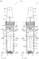
图25是关于第1实施方式的电动牙刷的牙刷主体,图25(a)相当于图22和图23中的D22A-D22A平面的剖面构造,是表示作为主体壳体和把持壳体之间的相对旋转状态的断开状态的剖视图,图25(b)相当于图22和图23中的D22B-D22B平面的剖面构造,是表示作为主体壳体和把持壳体之间的相对旋转状态的断开状态的剖视图。Fig. 25 is the toothbrush main body of the electric toothbrush according to the first embodiment. Fig. 25(a) corresponds to the cross-sectional structure of the D22A-D22A plane in Fig. 22 and Fig. The cross-sectional view of the disconnected state of the relative rotation state, Fig. 25(b) is equivalent to the cross-sectional structure of the D22B-D22B plane in Fig. 22 and Fig. Cutaway view of the open state.

图26是关于第1实施方式的电动牙刷的牙刷主体,图26(a)相当于图22和图23中的D22A-D22A平面的剖面构造,是表示作为主体壳体和把持壳体之间的相对旋转状态的接通状态的剖视图,图26(b)相当于图22和图23中的D22B-D22B平面的剖面构造,是表示作为主体壳体和把持壳体之间的相对旋转状态的接通状态的剖视图。Fig. 26 is the toothbrush main body of the electric toothbrush according to the first embodiment. Fig. 26(a) corresponds to the cross-sectional structure of the D22A-D22A plane in Fig. 22 and Fig. The cross-sectional view of the on state of the relative rotation state, Fig. 26(b) is equivalent to the cross-sectional structure of the D22B-D22B plane in Fig. 22 and Fig. Cross-sectional view of the open state.

图27是关于第1实施方式的电动牙刷的阳极配件,图27(a)是表示顶面构造的俯视图,图27(b)是表示左侧面构造的侧视图,图27(c)是表示正面构造的主视图。Fig. 27 is the anode assembly of the electric toothbrush according to the first embodiment, Fig. 27(a) is a plan view showing the top structure, Fig. 27(b) is a side view showing the left side structure, and Fig. 27(c) is a view showing Frontal view of the construction.

图28是关于第1实施方式的电动牙刷的把持壳体,图28(a)是表示顶面构造的俯视图,图28(b)是表示图22和图23中的D22C-D22C平面的剖面构造,且表示省略了内壳和干电池的状态的剖视图,图28(c)是表示图22和图23中的D22C-D22C平面的剖面构造,且表示省略了干电池的状态的剖视图。Fig. 28 is a gripping case of the electric toothbrush according to the first embodiment, Fig. 28(a) is a plan view showing the top surface structure, and Fig. 28(b) is a cross-sectional structure showing the D22C-D22C plane in Fig. 22 and Fig. 23 , and shows a sectional view of the state where the inner case and the dry battery are omitted, and FIG. 28(c) is a sectional view showing the sectional structure of the D22C-D22C plane in FIG. 22 and FIG. 23 , and shows a sectional view of the state where the dry battery is omitted.

图29是关于第1实施方式的电动牙刷的把持壳体,图29(a)是表示图28(b)中的立体构造的立体图,图29(b)是表示图28(c)中的立体构造的立体图。Fig. 29 is a gripping case of the electric toothbrush according to the first embodiment, Fig. 29(a) is a perspective view showing the three-dimensional structure in Fig. 28(b), and Fig. 29(b) is a perspective view showing the three-dimensional structure in Fig. 28(c) Constructed stereogram.

图30是关于第1实施方式的电动牙刷的把持壳体,图30(a)是表示在图29(b)中插入有干电池的状态的立体图,图30(b)是表示从图30(a)中的XZ平面的向右方看到的剖面构造的剖视图。30 is a gripping case of the electric toothbrush according to the first embodiment. FIG. 30( a ) is a perspective view showing a state in which a dry battery is inserted in FIG. 29( b ), and FIG. ) is a cross-sectional view of the cross-sectional structure seen from the right on the XZ plane.

图31是关于第2实施方式的口腔卫生装置的电动牙刷,图31(a)是表示在牙刷附件的局部剖开状态下的立体构造的立体图,图31(b)是表示牙渍护理附件(日语:ステインケアアタッチメント)从牙刷主体分离的状态的立体图。Fig. 31 is an electric toothbrush related to the oral hygiene device of the second embodiment, Fig. 31(a) is a perspective view showing a three-dimensional structure in a partially cutaway state of the toothbrush attachment, and Fig. 31(b) is a perspective view showing a stain care attachment ( Japanese: ステインケアアタッチメント) is a perspective view of the state separated from the toothbrush main body.

具体实施方式Detailed ways

(第1实施方式)(first embodiment)

对便携式口腔卫生装置1的用语进行如下定义。The terms of the portable oral hygiene device 1 are defined as follows.

(A)Z方向表示装置1的长度方向。(A) The Z direction represents the longitudinal direction of the device 1 .

(B)Y方向表示在装置1的正面观察,与Z方向正交的方向。(B) The Y direction represents the direction perpendicular to the Z direction when viewed from the front of the device 1 .

(C)X方向表示在装置1的侧面观察,与Z方向正交的方向。(C) The X direction represents a direction perpendicular to the Z direction when viewed from the side of the device 1 .

(D)X轴表示规定X方向的坐标轴。(D) The X-axis represents a coordinate axis that defines the X-direction.

(E)Y轴表示规定Y方向的坐标轴。(E) The Y axis represents a coordinate axis that defines the Y direction.

(F)Z轴表示规定Z方向的坐标轴。(F) The Z axis represents a coordinate axis that specifies the Z direction.

(G)XY平面表示由X轴和Y轴规定的平面。(G) The XY plane represents a plane defined by the X axis and the Y axis.

(H)XZ平面表示由X轴和Z轴规定的平面。(H) The XZ plane represents a plane defined by the X axis and the Z axis.

(I)YZ平面表示由Y轴和Z轴规定的平面。(I) YZ plane means a plane defined by the Y axis and the Z axis.

(J)前方XA表示在X方向上从背面侧朝向正面侧的方向。(J) Front XA represents the direction from the back side toward the front side in the X direction.

(K)后方XB表示在X方向上从正面侧朝向背面侧的方向。(K) Rear XB represents the direction from the front side toward the back side in the X direction.

(L)右方YA表示在正面观察到的Y方向上从左侧朝向右侧的方向。(L) Right YA indicates a direction from the left to the right in the Y direction viewed from the front.

(M)左方YB表示在正面观察到的Y方向上从右侧朝向左侧的方向。(M) Left YB indicates the direction from the right to the left in the Y direction viewed from the front.

(N)上方ZA表示在Z方向上从装置1的底部朝向顶端的方向。(N) Upper ZA indicates the direction from the bottom of the device 1 toward the top in the Z direction.

(O)下方ZB表示在Z方向上从装置1的顶端朝向底部的方向。(O) Bottom ZB indicates a direction from the top of the device 1 toward the bottom in the Z direction.

(P)矢径方向表示在XY平面上以Z轴为中心的矢径的方向。(P) The radial direction represents the direction of the radial direction centered on the Z-axis on the XY plane.

(Q)外方向表示在矢径方向上从Z轴远离的方向。The (Q) outward direction indicates a direction away from the Z-axis in the sagittal direction.

(R)内方向表示在矢径方向上向Z轴接近的方向。(R) The inner direction represents the direction approaching the Z-axis in the sagittal direction.

需要说明的是,在矢径方向上,对于将中心轴线与其他的点之间进行2点连接而成的线段而言,在将通过让中心轴线固定并且移动其他的点而形成的圆作为虚拟圆时,上述线段与该虚拟圆的半径相当。It should be noted that, in the sagittal direction, for a line segment formed by connecting two points between the central axis and other points, a circle formed by fixing the central axis and moving other points is used as a virtual When a circle is formed, the above-mentioned line segment is equivalent to the radius of the virtual circle.

图1(a)表示便携式口腔卫生装置1的外观立体构造。便携式口腔卫生装置1具有:电动牙刷2,其用于清洁牙齿;以及罩80,其用于保护电动牙刷2的牙刷附件50。罩80具有:外周壁部81,其覆盖牙刷附件50的四周;以及上侧壁部82,其用于封堵外周壁部81的上侧的开口部分。上侧壁部82具有2个通气孔82A,该通气孔82A具有圆弧形状。需要说明的是,便携式口腔卫生装置1是“口腔卫生装置”的一个例子。此外,牙刷附件50是“功能部件”的一个例子。FIG. 1( a ) shows the external appearance three-dimensional structure of the portable oral hygiene device 1 . The portable oral hygiene device 1 has: an electric toothbrush 2 for cleaning teeth; and a cover 80 for protecting the toothbrush attachment 50 of the electric toothbrush 2 . The cover 80 has an outer peripheral wall 81 covering the periphery of the toothbrush attachment 50 , and an upper side wall 82 for closing an upper opening of the outer peripheral wall 81 . The upper side wall portion 82 has two vent holes 82A having an arc shape. In addition, the portable oral hygiene device 1 is an example of an "oral hygiene device". In addition, the toothbrush attachment 50 is an example of a "functional part".

图1(b)是表示在图1(a)中罩80被XZ平面剖开的便携式口腔卫生装置1。电动牙刷2具有:牙刷主体10,其内置有各种部件;以及牙刷附件50,其嵌入有多个毛束51。FIG. 1( b ) shows the portable oral hygiene device 1 in which the cover 80 is cut along the XZ plane in FIG. 1( a ). The electric toothbrush 2 has a toothbrush main body 10 in which various components are built in, and a toothbrush attachment 50 in which a plurality of hair bundles 51 are embedded.

图2(a)是表示在图1(b)中省略了罩80的便携式口腔卫生装置1、即电动牙刷2。牙刷主体10具有:主体壳体11,其与牙刷附件50结合;把持壳体70,其供使用者把持;以及装饰环12,其用于提高电动牙刷2的美观度。FIG. 2( a ) shows the portable oral hygiene device 1 , that is, the electric toothbrush 2 , in which the cover 80 is omitted in FIG. 1( b ). The toothbrush main body 10 has: a main body housing 11 combined with the toothbrush attachment 50 ; a handle housing 70 for the user to hold; and a decorative ring 12 for improving the aesthetics of the electric toothbrush 2 .

装饰环12具有多个装饰部分12A(参照图5(a))。单个装饰部分12A具有四角锥形状。各装饰部分12A在装饰环12的周向以等间隔形成。装饰环12的外表面(以下称为“装饰面12Z”)具有以2点以上的部位与便携式口腔卫生装置1的设置面接触的形状。此外,装饰面12Z利用蒸镀用塗料来涂装。蒸镀的涂料形成为具有金属光泽的皮膜。The decoration ring 12 has a plurality of decoration parts 12A (see FIG. 5( a )). The single decorative portion 12A has a quadrangular pyramid shape. The decorative portions 12A are formed at equal intervals in the circumferential direction of the decorative ring 12 . The outer surface of the decoration ring 12 (hereinafter referred to as "decoration surface 12Z") has a shape in which two or more points are in contact with the installation surface of the portable oral hygiene device 1 . In addition, the decorative surface 12Z is painted with a paint for vapor deposition. The vapor-deposited paint forms a metallic luster film.

图2(b)是表示在图2(a)中牙刷附件50被XZ平面剖开的电动牙刷2。主体壳体11的局部位于牙刷附件50内的空间。FIG. 2( b ) shows the electric toothbrush 2 in which the toothbrush attachment 50 is cut along the XZ plane in FIG. 2( a ). Part of the main body housing 11 is located in the space inside the toothbrush attachment 50 .

图3(a)是表示在图2(b)中把持壳体70被XZ平面剖开的电动牙刷2。主体壳体11具有:外壳20,其具有暴露在外部的部分;以及内壳30,其被把持壳体70和外壳20所覆盖。把持壳体70具有:外周壁部71,其覆盖外壳20和内壳30的四周;下侧壁部72,其用于封堵外周壁部71的下侧的开口部分;以及防水薄膜(省略图示),其粘贴于下侧壁部72的外表面。FIG. 3( a ) shows the electric toothbrush 2 in which the grip housing 70 is cut along the XZ plane in FIG. 2( b ). The main body case 11 has: an outer case 20 having a portion exposed to the outside; and an inner case 30 covered by the grip case 70 and the outer case 20 . The handle housing 70 has: an outer peripheral wall portion 71 covering the surroundings of the outer casing 20 and the inner casing 30; a lower side wall portion 72 for closing the lower opening of the outer peripheral wall portion 71; and a waterproof film (not shown in the figure). shown), which is pasted on the outer surface of the lower side wall portion 72.

图5(d)表示下侧壁部72的平面构造。下侧壁部72具有:中间凹部72A,其从把持壳体70的外表面侧向内部的空间侧凹陷;4个槽72B,其用于连接中间凹部72A和外周壁部71;以及通气孔72C,其用于使把持壳体70的内部空间与外部空间之间彼此连通。需要说明的是,中间凹部72A、4个槽72B以及通气孔72C均被上述防水薄膜覆盖。FIG. 5( d ) shows the planar structure of the lower side wall portion 72 . The lower side wall portion 72 has: a middle concave portion 72A, which is recessed from the outer surface side of the grip housing 70 toward the inner space side; four grooves 72B, which are used to connect the middle concave portion 72A and the outer peripheral wall portion 71; and a vent hole 72C , which is used to make the inner space and the outer space of the handle housing 70 communicate with each other. It should be noted that the middle concave portion 72A, the four grooves 72B, and the ventilation holes 72C are all covered by the above-mentioned waterproof film.

图3(b)是表示在图3(a)中外壳20和装饰环12被XZ平面剖开的电动牙刷2。内壳30的局部位于外壳20内的空间。在外壳20上设置有用于将主体壳体11和把持壳体70之间的间隙密封起来的弹性构件25。FIG. 3( b ) shows the electric toothbrush 2 in which the casing 20 and the decorative ring 12 are cut along the XZ plane in FIG. 3( a ). Part of the inner case 30 is located in the space inside the outer case 20 . An elastic member 25 for sealing the gap between the main body case 11 and the handle case 70 is provided on the case 20 .

图4(a)是表示在图3(b)中内壳30被XZ平面剖开的电动牙刷2。内壳30保持有:振动产生装置40,其用于使牙刷附件50振动;以及电池保持部分31(参照图7),其用于保持干电池3。振动产生装置40具有电动机41、偏心砝码43以及隔离件44。FIG. 4( a ) shows the electric toothbrush 2 in which the inner casing 30 is cut along the XZ plane in FIG. 3( b ). The inner case 30 holds: a vibration generating device 40 for vibrating the toothbrush attachment 50 ; and a battery holding portion 31 (refer to FIG. 7 ) for holding the dry battery 3 . The vibration generator 40 has a motor 41 , an eccentric weight 43 and a spacer 44 .

图4(b)是表示从图4(a)中省略了干电池3的电动牙刷2。在把持壳体70上设置有用于与干电池3的阳极接触的阳极配件64。在内壳30设置有:通电配件67,其与阳极配件64连接;阴极配件63,其用于与干电池3的阴极接触;以及电路基板61,其用于将通电配件67以及阴极配件63与电动机41彼此连接起来。需要说明的是,阳极配件64是“把持侧电极”的一个例子。此外,通电配件67是“导电构件”的一个例子。FIG. 4( b ) shows the electric toothbrush 2 in which the dry battery 3 is omitted from FIG. 4( a ). An anode fitting 64 for contacting the anode of the dry battery 3 is provided on the handle case 70 . The inner casing 30 is provided with: an energizing fitting 67, which is connected to the anode fitting 64; a cathode fitting 63, which is used to contact the cathode of the dry battery 3; and a circuit board 61, which is used to connect the energizing fitting 67 and the cathode fitting 63 to the motor. 41 are connected to each other. In addition, the anode metal fitting 64 is an example of a "grip-side electrode". In addition, the conduction fitting 67 is an example of a "conductive member".

作为主体壳体11的材料,使用比牙刷附件50的刷柄53的材料硬的材料。作为主体壳体11和刷柄53的材料的组合,例如举出以下的材料组合。作为主体壳体11的材料,使用加入玻璃纤维的ABS树脂,作为刷柄53的材料,使用聚甲醛树脂。或者,使用ABS树脂作为主体壳体11的材料,使用聚丙烯树脂作为刷柄53的材料。总之,只要是具有为了维持主体壳体11和刷柄53的各自的功能所需要的硬度,并且主体壳体11具有比刷柄53硬度高的材料的组合,就能够不限于这里所例示出来的组合地选择其他的组合。As the material of the main body case 11, a material harder than the material of the handle 53 of the toothbrush attachment 50 is used. As a combination of materials of the main body case 11 and the handle 53, the following material combinations are mentioned, for example. As the material of the main body case 11, ABS resin containing glass fibers is used, and as the material of the handle 53, acetal resin is used. Alternatively, ABS resin is used as the material of the main body case 11 and polypropylene resin is used as the material of the handle 53 . In short, as long as it has the hardness required to maintain the respective functions of the main body case 11 and the handle 53, and the main body case 11 has a material combination with a hardness higher than that of the handle 53, it is not limited to the examples shown here. Other combinations are selected in combination.

需要说明的是,主体壳体11中的外壳20出于以下的目的而优选使用比上述刷柄53硬的材料,即,即使反复执行规定次数的、与牙刷附件50的结合及分离,也能维持必要的功能。另一方面,对于主体壳体11中的内壳30而言,即使使用比刷柄53柔软的材料,也不存在伴随着主体壳体11和牙刷附件50之间的结合及分离而降低耐久性的问题,因此,也能够选择与外壳20不同的材料。It should be noted that the housing 20 in the main body housing 11 is preferably made of a material harder than the above-mentioned handle 53 for the following purpose, that is, even if the combination and separation with the toothbrush attachment 50 are repeated for a predetermined number of times, the maintain necessary functions. On the other hand, for the inner case 30 in the main body case 11, even if a material softer than the handle 53 is used, there is no decrease in durability accompanying the coupling and separation between the main body case 11 and the toothbrush attachment 50. Therefore, it is also possible to choose a material different from that of the housing 20 .

参照图5,说明便携式口腔卫生装置1的外观的结构。图5(a)表示便携式口腔卫生装置1的左侧面构造。图5(b)表示便携式口腔卫生装置1的正面构造。图5(c)表示便携式口腔卫生装置1的顶面构造。图5(d)表示便携式口腔卫生装置1的底面构造。Referring to FIG. 5 , the structure of the appearance of the portable oral hygiene device 1 will be described. FIG. 5( a ) shows the left side structure of the portable oral hygiene device 1 . FIG. 5( b ) shows the front structure of the portable oral hygiene device 1 . FIG. 5( c ) shows the top surface structure of the portable oral hygiene device 1 . FIG. 5( d ) shows the bottom surface structure of the portable oral hygiene device 1 .

便携式口腔卫生装置1的外表面1Z具有罩80的外表面(以下称为“罩外表面80Z”)、装饰面12Z以及把持壳体70的外表面(以下称为“把持外表面70Z”)。罩外表面80Z和把持外表面70Z具有平滑弯曲的形状。The outer surface 1Z of the portable oral hygiene device 1 has the outer surface of the cover 80 (hereinafter referred to as “cover outer surface 80Z”), the decorative surface 12Z, and the outer surface of the grip housing 70 (hereinafter referred to as “grip outer surface 70Z”). The cover outer surface 80Z and the grip outer surface 70Z have smoothly curved shapes.

如图5(c)所示,装饰面12Z遍及罩外表面80Z的整周且位于比罩外表面80Z靠外侧方向的位置。此外,如图5(d)所示,装饰面12Z遍及把持外表面70Z的整周且位于比把持外表面70Z靠外侧方向的位置。As shown in FIG. 5( c ), the decorative surface 12Z extends over the entire circumference of the cover outer surface 80Z and is positioned in the outer direction from the cover outer surface 80Z. In addition, as shown in FIG. 5( d ), the decorative surface 12Z extends over the entire circumference of the grip outer surface 70Z and is positioned in the outer direction from the grip outer surface 70Z.

如图5(a)所示,在与罩外表面80Z和把持外表面70Z的正面以及背面相对应的位置,装饰部分12A从罩外表面80Z和把持外表面70Z向外侧方向突出规定突出量LA。需要说明的是,规定突出量LA相当于装饰部分12A中最向外侧方向突出的部分与罩外表面80Z以及把持外表面70Z之间的距离。As shown in FIG. 5( a ), at positions corresponding to the front and back surfaces of the cover outer surface 80Z and the grip outer surface 70Z, the decorative portion 12A protrudes outward by a predetermined amount LA from the cover outer surface 80Z and the grip outer surface 70Z. . In addition, the predetermined protrusion amount LA corresponds to the distance between the part which protrudes most outwardly in the decoration part 12A, and the cover outer surface 80Z and the grip outer surface 70Z.

如图5(b)所示,在与罩外表面80Z和把持外表面70Z的右侧面以及左侧面相对应的位置,装饰部分12A从罩外表面80Z和把持外表面70Z向外侧方向突出规定突出量LB。规定突出量LB比规定突出量LA大。需要说明的是,规定突出量LB相当于装饰部分12A中最向外侧方向突出的部分与罩外表面80Z以及把持外表面70Z之间的距离。As shown in FIG. 5( b ), at positions corresponding to the right side and the left side of the cover outer surface 80Z and the grip outer surface 70Z, the decorative portion 12A protrudes from the cover outer surface 80Z and the grip outer surface 70Z in a predetermined direction outward. Protrusion amount LB. The predetermined protrusion amount LB is larger than the predetermined protrusion amount LA. In addition, predetermined protrusion amount LB is corresponded to the distance between the part which protrudes the most outward direction among the decoration parts 12A, and the cover outer surface 80Z and the grip outer surface 70Z.

参照图6说明电动牙刷2的外观的结构。图6(a)表示电动牙刷2的左侧面构造。图6(b)表示电动牙刷2的正面构造。图6(c)表示电动牙刷2的顶面构造。图6(d)表示电动牙刷2的底面构造。The structure of the appearance of the electric toothbrush 2 will be described with reference to FIG. 6 . FIG. 6( a ) shows the structure of the left side of the electric toothbrush 2 . FIG. 6( b ) shows the front structure of the electric toothbrush 2 . FIG. 6( c ) shows the top surface structure of the electric toothbrush 2 . FIG. 6( d ) shows the bottom surface structure of the electric toothbrush 2 .

电动牙刷2的外表面2Z具有牙刷附件50的外表面(以下称为“牙刷面50Z”)、外壳20的外表面20Z、装饰面12Z以及把持外表面70Z。The outer surface 2Z of the electric toothbrush 2 has the outer surface of the toothbrush attachment 50 (hereinafter referred to as "toothbrush surface 50Z"), the outer surface 20Z of the case 20, the decorative surface 12Z, and the grip outer surface 70Z.

如图6(c)所示,装饰面12Z遍及牙刷面50Z和外壳20的外表面20Z的整周且位于比牙刷面50Z和外壳20的外表面20Z靠外侧方向的位置。As shown in FIG. 6( c ), the decorative surface 12Z extends over the entire circumference of the toothbrush surface 50Z and the outer surface 20Z of the housing 20 and is located on the outer side of the toothbrush surface 50Z and the outer surface 20Z of the housing 20 .

如图6(a)所示,在与外壳20的外表面20Z的正面以及背面相对应的位置,装饰部分12A从外壳20的外表面20Z向外侧方向突出规定突出量LC。需要说明的是,规定突出量LC相当于装饰部分12A中最向外侧方向突出的部分和外壳20的外表面20Z之间的距离。As shown in FIG. 6( a ), at positions corresponding to the front and rear surfaces of the outer surface 20Z of the housing 20 , the decorative portion 12A protrudes outward by a predetermined amount LC from the outer surface 20Z of the housing 20 . It should be noted that the predetermined protrusion amount LC corresponds to the distance between the outer surface 20Z of the case 20 and the portion that protrudes most in the outer direction of the decorative portion 12A.

如图6(b)所示,在与外壳20的外表面20Z的右侧面以及左侧面相对应的位置,装饰部分12A从外壳20的外表面20Z向外侧方向突出规定突出量LD。规定突出量LD比规定突出量LC大。需要说明的是,规定突出量LD相当于装饰部分12A中最向外侧方向突出的部分和外壳20的外表面20Z之间的距离。As shown in FIG. 6( b ), at positions corresponding to the right and left sides of the outer surface 20Z of the housing 20 , the decorative portion 12A protrudes outward by a predetermined amount LD from the outer surface 20Z of the housing 20 . The predetermined protrusion amount LD is larger than the predetermined protrusion amount LC. It should be noted that the predetermined protrusion amount LD corresponds to the distance between the outer surface 20Z of the housing 20 and the most outwardly protruding portion of the decorative portion 12A.

参照图7和图8,说明各部件之间的结合构造。Referring to FIG. 7 and FIG. 8 , the connection structure between the various components will be described.

图7表示能分离地构成的便携式口腔卫生装置1的立体构造。使用者能够将便携式口腔卫生装置1拆分成电动牙刷2和罩80。此外,使用者能够将电动牙刷2拆分成牙刷主体10和牙刷附件50。此外,使用者能够将牙刷主体10拆分成主体壳体11和把持壳体70。FIG. 7 shows a three-dimensional structure of the portable oral hygiene device 1 which can be configured separately. The user can disassemble the portable oral hygiene device 1 into the electric toothbrush 2 and the cover 80 . In addition, the user can disassemble the electric toothbrush 2 into the toothbrush main body 10 and the toothbrush attachment 50 . In addition, the user can disassemble the toothbrush main body 10 into the main body case 11 and the handle case 70 .

主体壳体11具有外壳20和内壳30。内壳30具有用于收容干电池3的电池保持部分31。电池保持部分31具有开口部分31A,该开口部分31A供干电池3向电池保持部分31内的空间插入以及供干电池3从电池保持部分31内的空间取出。The main body case 11 has an outer case 20 and an inner case 30 . The inner case 30 has a battery holding portion 31 for housing the dry battery 3 . The battery holding portion 31 has an opening portion 31A for inserting the dry battery 3 into the space inside the battery holding portion 31 and for taking the dry battery 3 out of the space inside the battery holding portion 31 .

图8表示示意性的各部件之间的结合构造。Fig. 8 shows a schematic connection structure between the respective components.

便携式口腔卫生装置1具有以下4个结合构造。The portable oral hygiene device 1 has the following four combined structures.

(A)电动牙刷2和罩80具有能够使电动牙刷2和罩80彼此结合以及分离的罩结合构造R(参照图18)。罩结合构造R具有:2个外侧嵌合部分RA,其形成于外壳20的外表面20Z;以及2个罩侧嵌合部分RB,其形成于罩80的内表面(以下称为“罩内表面80W”)。(A) The electric toothbrush 2 and the cover 80 have a cover joint structure R (refer to FIG. 18 ) that enables the electric toothbrush 2 and the cover 80 to be coupled to and separated from each other. The cover coupling structure R has: two outer fitting portions RA formed on the outer surface 20Z of the casing 20; and two cover side fitting portions RB formed on the inner surface of the cover 80 (hereinafter referred to as “cover inner surface”). 80W").

(B)牙刷主体10和牙刷附件50具有能够使牙刷主体10和牙刷附件50彼此结合以及分离的牙刷结合构造S(参照图19)。牙刷结合构造S具有:1个外侧嵌合部分SA,其形成于外壳20的外表面20Z;以及牙刷侧嵌合部分SB,其形成于牙刷附件50的背面壁部。需要说明的是,牙刷结合构造S是“部件结合构造”的一个例子。(B) The toothbrush main body 10 and the toothbrush attachment 50 have a toothbrush coupling structure S (see FIG. 19 ) that enables the toothbrush main body 10 and the toothbrush attachment 50 to be coupled to and separated from each other. The toothbrush coupling structure S has one outer fitting portion SA formed on the outer surface 20Z of the housing 20 , and a toothbrush side fitting portion SB formed on the back wall of the toothbrush attachment 50 . In addition, the toothbrush joint structure S is an example of a "component joint structure".

(C)外壳20和内壳30具有能够使外壳20和内壳30彼此结合以及分离的主体结合构造T。主体结合构造T具有:2个内侧嵌合部分TA(参照图15),其形成于内壳30的外表面30Z;以及2个外侧嵌合部分TB(参照图13(a)和图13(b)),其形成于外壳20的外表面20Z。(C) The outer shell 20 and the inner shell 30 have a body coupling configuration T capable of coupling and separating the outer shell 20 and the inner shell 30 from each other. The body joint structure T has: 2 inner fitting parts TA (refer to FIG. 15 ), which are formed on the outer surface 30Z of the inner shell 30; and 2 outer fitting parts TB (refer to FIGS. 13( a ) and 13 ( b ). )), which are formed on the outer surface 20Z of the housing 20.

(D)主体壳体11和把持壳体70具有能够使主体壳体11和把持壳体70彼此结合以及分离的把持结合构造U。把持结合构造U具有:上侧把持结合构造UX(参照图24(a)),其限制或者允许把持壳体70相对于外壳20的相对旋转;以及下侧把持结合构造UY(参照图24(b)),其限制或者允许把持壳体70相对于内壳30的相对旋转。上侧把持结合构造UX和下侧把持结合构造UY通过协作使主体壳体11和把持壳体70之间结合或者分离。需要说明的是,把持结合构造U是“相对动作构造”的一个例子。此外,上侧把持结合构造UX是“第2旋转构造”的一个例子。此外,下侧把持结合构造UY是“第1旋转构造”的一个例子。(D) The main body case 11 and the grip case 70 have a grip joint structure U that enables the main body case 11 and the grip case 70 to be joined to and separated from each other. The holding joint structure U has: an upper holding joint structure UX (see FIG. )), which limit or allow the relative rotation of the handle housing 70 relative to the inner housing 30 . The upper grip coupling structure UX and the lower grip coupling structure UY cooperate to couple or separate the main body case 11 and the grip case 70 . It should be noted that the grip joint structure U is an example of the "relative motion structure". In addition, the upper side grip connection structure UX is an example of "the 2nd rotation structure". In addition, the lower side grip connection structure UY is an example of a "1st rotation structure".

上侧把持结合构造UX(参照图24(a))具有:2个把持侧嵌合部分UA,其形成于把持壳体70的内表面(以下称为“把持内表面70W”);以及2个外侧嵌合部分UB,其形成于外壳20的外表面20Z。The upper grip joint structure UX (see FIG. 24( a )) has: two grip side fitting parts UA formed on the inner surface of the grip housing 70 (hereinafter referred to as "grip inner surface 70W"); and two The outer fitting portion UB is formed on the outer surface 20Z of the housing 20 .

下侧把持结合构造UY(参照图24(b))具有:2个把持侧嵌合部分UC,其形成于把持内表面70W;以及1个内侧嵌合部分UD,其形成于内壳30的外表面30Z。The lower side grip joint structure UY (see FIG. 24( b )) has: two grip side fitting portions UC formed on the grip inner surface 70W; and one inner fitting portion UD formed on the outer surface of the inner case 30 Surface 30Z.

需要说明的是,便携式口腔卫生装置1的各结合构造R、S、T、U的结合状态是指,在对利用各自的结合构造彼此结合起来的2个部件没有力作用时,或者对2个部件向使该2个部件彼此分离的方向作用的力小于规定的力时,这2个部件的相对运动被限制的状态。It should be noted that the connection state of each connection structure R, S, T, U of the portable oral hygiene device 1 refers to when there is no force acting on the two components connected to each other by the respective connection structures, or when the two components are connected to each other. A state in which the relative movement of the two parts is restricted when the force acting on the parts in the direction of separating the two parts is less than a predetermined force.

图9(a)表示图5(c)中的D5A-D5A平面的剖面构造。图9(b)表示图5(c)的D5B-D5B平面的剖面构造。图9(a)和图9(b)示出了位于主体壳体11内的各部件。FIG.9(a) has shown the cross-sectional structure of the D5A-D5A plane in FIG.5(c). FIG.9(b) has shown the cross-sectional structure of the D5B-D5B plane of FIG.5(c). FIG. 9( a ) and FIG. 9( b ) show various components located inside the main body casing 11 .

上部结合部分21整体位于牙刷附件50内。电动机41整体位于上部结合部分21内。中间结合部分22的外表面与罩内表面80W相对。内壳30中的上侧的部分位于外壳20内。内壳30中的下侧的部分位于把持壳体70内。The upper engaging portion 21 is integrally located within the toothbrush attachment 50 . The motor 41 is located entirely within the upper coupling portion 21 . The outer surface of the intermediate joining portion 22 is opposed to the cover inner surface 80W. The upper part of the inner case 30 is located inside the outer case 20 . The lower part of the inner case 30 is located in the grip housing 70 .

参照图10说明罩80的结构。图10(a)表示罩80的正面构造。图10(b)表示从图10(a)中的D10A-D10A平面向右方YA看到的、罩80的剖面构造。图10(c)表示从图10(a)的D10A-D10A平面向左方YB看到的、罩80的剖面构造。图10(d)表示从图10(a)~图10(c)中的D10B-D10B平面向下方ZB看到的、罩80的剖面构造。图10(e)表示从图10(a)~图10(c)中的D10C-D10C平面向下方ZB看到的、罩80的剖面构造。图10(f)表示从图10(a)~图10(c)中的D10D-D10D平面向下方ZB看到的、罩80的剖面构造。需要说明的是,图10中省略了各坐标轴。关于图10说明中的坐标,与图1~图9所示出的坐标相同。The structure of the cover 80 will be described with reference to FIG. 10 . FIG. 10( a ) shows the front structure of the cover 80 . FIG.10(b) has shown the cross-sectional structure of the cover 80 seen from D10A-D10A plane in FIG.10(a) toward right direction YA. FIG.10(c) has shown the cross-sectional structure of the cover 80 seen from D10A-D10A plane of FIG.10(a) toward left direction YB. FIG. 10( d ) shows the cross-sectional structure of the cover 80 seen from the D10B-D10B plane in FIGS. 10( a ) to 10( c ) downward ZB. FIG.10(e) has shown the cross-sectional structure of the cover 80 seen from the D10C-D10C plane in FIG.10(a) - FIG.10(c) toward the downward ZB. FIG. 10( f ) shows the cross-sectional structure of the cover 80 seen from the D10D-D10D plane in FIGS. 10( a ) to 10( c ) downward ZB. It should be noted that each coordinate axis is omitted in FIG. 10 . The coordinates in the description of FIG. 10 are the same as those shown in FIGS. 1 to 9 .

罩80具有:2个接触部分83,其通过与牙刷附件50和外壳20接触来引导牙刷附件50和外壳20的移动;以及2个罩侧嵌合部分RB,其构成罩结合构造R。各接触部分83从罩80的开口部分84一直形成到上侧壁部82。一个接触部分83与另一个接触部分83具有以X轴为中心彼此相对的位置关系。各罩侧嵌合部分RB与接触部分83邻接并形成于罩80的开口部分84附近。此外,如图10(d)所示,各罩侧嵌合部分RB具有相对于区划接触部分83的罩内表面80W向外侧方向凹陷的形状。The cover 80 has: two contact portions 83 that guide the movement of the toothbrush attachment 50 and the housing 20 by contacting the toothbrush attachment 50 and the housing 20 ; Each contact portion 83 is formed from the opening portion 84 of the cover 80 to the upper side wall portion 82 . One contact portion 83 and the other contact portion 83 have a positional relationship facing each other centering on the X-axis. Each cover-side fitting portion RB is adjacent to the contact portion 83 and formed near the opening portion 84 of the cover 80 . In addition, as shown in FIG. 10( d ), each cover-side fitting portion RB has a shape dented outward with respect to the cover inner surface 80W of the partitioned contact portion 83 .

参照图11说明把持壳体70的结构。图11(a)表示把持壳体70的正面构造。图11(b)表示从图11(a)中的D11A-D11A平面向右方YA看到的、把持壳体70的剖面构造。图11(c)表示从图11(a)中的D11B-D11B平面向后方ZB看到的、把持壳体70的剖面构造。图11(d)表示从图11(a)~图11(c)中的D11B-D11B平面向下方ZB看到的、把持壳体70的剖面构造。图11(e)表示从图11(a)~图11(c)中的D11C-D11C平面向下方ZB看到的、把持壳体70的剖面构造。图11(f)表示从图11(a)~图11(c)中的D11D-D11D平面向下方ZB看到的、把持壳体70的剖面构造。需要说明的是,图11中省略了各坐标轴。关于图11说明中的坐标,与图1~图9所示出的坐标相同。The structure of the grip housing 70 will be described with reference to FIG. 11 . FIG. 11( a ) shows the front structure of the grip housing 70 . FIG.11(b) has shown the cross-sectional structure of the grip housing 70 seen from D11A-D11A plane in FIG.11(a) toward right direction YA. FIG. 11( c ) shows the cross-sectional structure of the grip housing 70 as viewed from the D11B-D11B plane in FIG. 11( a ) toward the rear ZB. FIG.11(d) has shown the cross-sectional structure of the grip housing 70 seen from the D11B-D11B plane in FIG.11(a)-FIG.11(c) toward ZB downward. FIG.11(e) has shown the cross-sectional structure of the grip housing 70 seen from the D11C-D11C plane in FIG.11(a)-FIG.11(c) toward the downward direction ZB. FIG. 11( f ) shows the cross-sectional structure of the grip housing 70 as viewed from the D11D-D11D plane in FIGS. 11( a ) to 11( c ) downward ZB. It should be noted that each coordinate axis is omitted in FIG. 11 . The coordinates in the description of FIG. 11 are the same as those shown in FIGS. 1 to 9 .

把持壳体70具有:2个把持侧嵌合部分UA,其构成上侧把持结合构造UX;2个把持侧嵌合部分UC,其构成下侧把持结合构造UY;以及2个纵肋76,其从把持内表面70W向内侧方向突出。此外,在此基础上,把持壳体70具有:固定部分74,其用于固定阳极配件64(参照图4);以及开口部分73,其供主体壳体11向内部的空间插入。The grip housing 70 has: 2 grip side fitting parts UA, which constitute the upper grip joint structure UX; 2 grip side fitting parts UC, which constitute the lower side grip junction structure UY; and 2 longitudinal ribs 76, which It protrudes inwardly from the grip inner surface 70W. Further, based on this, the grip housing 70 has: a fixing portion 74 for fixing the anode fitting 64 (see FIG. 4 ); and an opening 73 for inserting the main body housing 11 into the internal space.

各把持侧嵌合部分UA在把持内表面70W上位于开口部分73附近。一个把持侧嵌合部分UA与另一个把持侧嵌合部分UA以X轴为中心彼此相对。Each grip side fitting portion UA is located near the opening portion 73 on the grip inner surface 70W. One holding side fitting part UA and the other holding side fitting part UA are opposed to each other centering on the X axis.

各把持侧嵌合部分UC在Z方向上从把持壳体70的下侧壁部72一直形成到中间部分。一个把持侧嵌合部分UC与另一个把持侧嵌合部分UC在周向上具有与内壳30的内侧嵌合部分UD(参照图15)的大小相对应的间隔。Each grip side fitting portion UC is formed from the lower side wall portion 72 of the grip housing 70 to the middle portion in the Z direction. One holding-side fitting portion UC and the other holding-side fitting portion UC have an interval corresponding to the size of the inner fitting portion UD (see FIG. 15 ) of the inner case 30 in the circumferential direction.

各纵肋76在绕Z轴的方向上形成在与把持侧嵌合部分UA相对应的位置。此外,各纵肋76在Z方向上从把持壳体70的下侧壁部72形成到把持侧嵌合部分UA的下方附近。Each of the vertical ribs 76 is formed at a position corresponding to the grip-side fitting portion UA in the direction around the Z-axis. In addition, each vertical rib 76 is formed from the lower side wall part 72 of the grip housing 70 to the vicinity of the lower side of the grip side fitting part UA in the Z direction.

参照图12说明牙刷附件50的结构。图12(a)表示牙刷附件50的正面构造。图12(b)表示牙刷附件50的背面构造。图12(c)表示从图12(a)中的D12A-D12A平面向右方YA看到的、牙刷附件50的剖面构造。图12(d)表示从图12(a)~图12(c)中的D12B-D12B平面向下方ZB看到的、牙刷附件50的剖面构造。图12(e)表示从图12(a)~图12(c)中的D12C-D12C平面向下方ZB看到的、牙刷附件50的剖面构造。图12(f)表示从图12(a)~图12(c)中的D12D-D12D平面向下方ZB看到的、牙刷附件50的剖面构造。需要说明的是,图12中省略了各坐标轴。关于图12说明中的坐标,与图1~图9所示出的坐标相同。The structure of the toothbrush attachment 50 will be described with reference to FIG. 12 . FIG. 12( a ) shows the front structure of the toothbrush attachment 50 . FIG. 12( b ) shows the back structure of the toothbrush attachment 50 . FIG.12(c) has shown the cross-sectional structure of the toothbrush attachment 50 seen from D12A-D12A plane in FIG.12(a) toward right direction YA. FIG.12(d) has shown the cross-sectional structure of the toothbrush attachment 50 seen from the D12B-D12B plane in FIG.12(a)-FIG.12(c) toward ZB downward. FIG.12(e) has shown the cross-sectional structure of the toothbrush attachment 50 seen from the D12C-D12C plane in FIG.12(a) - FIG.12(c) toward ZB downward. FIG.12(f) has shown the cross-sectional structure of the toothbrush attachment 50 seen from the D12D-D12D plane in FIG.12(a)-FIG.12(c) toward ZB downward. It should be noted that each coordinate axis is omitted in FIG. 12 . The coordinates in the description of FIG. 12 are the same as those shown in FIGS. 1 to 9 .

牙刷附件50具有:多个毛束51,其用于清洁牙齿;刷头52,其嵌入有各毛束51;以及刷柄53,其能与主体壳体11结合。刷头52和刷柄53由相同的树脂材料形成为单个部件。The toothbrush attachment 50 has: a plurality of tufts 51 for cleaning teeth; a brush head 52 in which each tuft 51 is embedded; and a handle 53 capable of being combined with the main body casing 11 . The brush head 52 and the handle 53 are formed as a single part from the same resin material.

刷柄53具有:牙刷侧嵌合部分SB,其构成牙刷结合构造S;以及引导肋54,其能嵌入于外壳20的引导槽21A(参照图13(c))。此外,在此基础上,刷柄53具有旋转结合构造55,旋转结合构造55用于使刷柄53与不同于外壳20的另一构造的外壳(以下称为“另一构造壳体”)彼此结合及分离。另一构造壳体具有:另一构造嵌合凸部,其用于与牙刷侧嵌合部分SB结合及分离;以及另一构造操作感赋予部,其在使用者将牙刷附件50与另一构造壳体之间结合时,用于向使用者赋予操作感。需要说明的是,另一构造壳体的图示省略。The handle 53 has a toothbrush-side fitting portion SB constituting the toothbrush joint structure S, and a guide rib 54 that can be fitted into the guide groove 21A of the housing 20 (see FIG. 13( c )). In addition, on this basis, the brush handle 53 has a rotating coupling structure 55 for making the brush handle 53 and a housing of another configuration different from the housing 20 (hereinafter referred to as “another configuration housing”) interact with each other. Combine and separate. Another configuration casing has: another configuration fitting convex portion for joining and separating from the toothbrush side fitting portion SB; When the casings are joined together, it is used to provide a user with an operational feeling. It should be noted that the illustration of another structural shell is omitted.

牙刷侧嵌合部分SB具有在刷柄53的背面壁部形成的贯通孔。引导肋54从牙刷附件50的开口部分59形成到Z方向的中间部分。The toothbrush-side fitting portion SB has a through hole formed in the rear wall portion of the handle 53 . The guide rib 54 is formed from the opening portion 59 of the toothbrush attachment 50 to the middle portion in the Z direction.

旋转结合构造55具有:凹嵌合部分56,其供另一构造操作感赋予部嵌入;操作感赋予部57,其用于向另一构造操作感赋予部赋予反作用力;以及旋转引导槽58,其用于将另一构造操作感赋予部向操作感赋予部57引导。The rotation coupling structure 55 has: a concave fitting portion 56 into which the operation feeling imparting part of another structure is fitted; an operation feeling imparting part 57 for imparting a reaction force to the operation feeling imparting part of the other structure; and a rotation guide groove 58 It is used to guide the other structural operation feeling imparting portion to the operating feeling imparting portion 57 .

凹嵌合部分56具有用于与嵌入到凹嵌合部分56的另一构造操作感赋予部相接触的限制立面56A。操作感赋予部57具有:引导斜面57A,其用于将另一构造操作感赋予部向凹嵌合部分56引导;限制立面57B,其用于与嵌入到凹嵌合部分56的另一构造操作感赋予部相接触;以及中间曲面57C,其用于连接引导斜面57A和限制立面57B。旋转引导槽58具有能将另一构造嵌合凸部从开口部分59引导到牙刷侧嵌合部分SB的形状。The concave fitting portion 56 has a restriction front surface 56A for coming into contact with another configuration operation feeling imparting portion fitted into the concave fitting portion 56 . The operation feeling imparting part 57 has: a guide slope 57A for guiding the operation feeling imparting part of another structure to the concave fitting part 56 ; The operational feeling imparting portion is in contact; and the intermediate curved surface 57C for connecting the guide slope 57A and the restriction elevation 57B. The rotation guide groove 58 has a shape capable of guiding another configuration fitting protrusion from the opening portion 59 to the toothbrush side fitting portion SB.

使用者将牙刷附件50结合于另一构造壳体时,将另一构造嵌合凸部插入于旋转引导槽58。接着,通过使牙刷附件50相对于另一构造壳体绕Z轴旋转,从而将另一构造嵌合凸部嵌入于牙刷侧嵌合部分SB。此时,另一构造操作感赋予部从旋转引导槽58经由引导斜面57A和中间曲面57C向凹嵌合部分56移动。另一构造操作感赋予部在越过引导斜面57A和中间曲面57C时,将来自操作感赋予部57的反作用力作为操作感而赋予给使用者。When the user combines the toothbrush attachment 50 with another structural housing, the user inserts the other structural fitting protrusion into the rotation guide groove 58 . Next, by rotating the toothbrush attachment 50 around the Z axis with respect to the other structure case, another structure fitting convex part is fitted in the toothbrush side fitting part SB. At this time, another configuration operation feeling imparting portion moves from the rotation guide groove 58 to the concave fitting portion 56 via the guide slope 57A and the intermediate curved surface 57C. In another configuration, the operational feeling imparting portion gives the user a reaction force from the operational feeling imparting portion 57 as an operational feeling when the user passes over the guide slope 57A and the intermediate curved surface 57C.

嵌入于牙刷侧嵌合部分SB的另一构造嵌合凸部通过与刷柄53的背面壁部接触而使其相对于刷柄53的移动受到限制。由此,将牙刷附件50结合于另一构造壳体。The other structural fitting convex part fitted in the toothbrush side fitting part SB contacts the back wall part of the handle 53, and the movement with respect to the handle 53 is restricted. Thus, the toothbrush attachment 50 is integrated into another construction housing.

使用者通过对刷柄53赋予为了使另一构造嵌合凸部从牙刷侧嵌合部分SB爬上刷柄53的背面壁部的内表面而向刷柄53赋予所需的力,从而能够使牙刷附件50从另一构造壳体分离。The user can apply the required force to the handle 53 to cause the other structural fitting protrusion to climb up from the toothbrush side fitting portion SB to the inner surface of the back wall portion of the handle 53, thereby enabling the The toothbrush attachment 50 is separate from the other construction housing.

参照图13说明外壳20的结构。图13(a)表示外壳20的左侧面构造。图13(b)表示外壳20的右侧面构造。图13(c)表示外壳20的正面构造。图13(d)表示外壳20的背面构造。The structure of the housing 20 will be described with reference to FIG. 13 . FIG. 13( a ) shows the structure of the left side of the case 20 . FIG. 13( b ) shows the right side structure of the casing 20 . FIG. 13( c ) shows the front structure of the casing 20 . FIG. 13( d ) shows the rear structure of the casing 20 .

外壳20具有:上部结合部分21,其用于与牙刷附件50结合;下部结合部分23,其用于与把持壳体70结合;以及中间结合部分22,其用于将上部结合部分21和下部结合部分23彼此连接起来。上部结合部分21、中间结合部分22以及下部结合部分23由相同的树脂材料形成为单个部件。The housing 20 has: an upper coupling portion 21 for coupling with the toothbrush attachment 50; a lower coupling portion 23 for coupling with the handle housing 70; and an intermediate coupling portion 22 for coupling the upper coupling portion 21 and the lower The sections 23 are connected to each other. The upper joint portion 21, the middle joint portion 22, and the lower joint portion 23 are formed of the same resin material as a single piece.

上部结合部分21具有:1个外侧嵌合部分SA,其构成牙刷结合构造S;以及引导槽21A,其用于将牙刷附件50的引导肋54向中间结合部分22的相对面22C引导。The upper joint part 21 has: one outer fitting part SA which comprises the toothbrush joint structure S;

中间结合部分22具有:2个外侧嵌合部分RA,其构成罩结合构造R;以及2个固定部分22A,其能嵌入装饰环12的凹部。此外,在此基础上,中间结合部分22具有:嵌合槽22B,其供弹性构件25(参照图3(a))嵌入;以及相对面22C,其与牙刷附件50的开口部分59侧的端面相对。各固定部分22A和各外侧嵌合部分RA具有从中间结合部分22的外表面沿着矢径方向突出的形状。The middle coupling part 22 has: two outer fitting parts RA constituting the cover coupling structure R; In addition, on this basis, the intermediate joint portion 22 has: a fitting groove 22B into which the elastic member 25 (refer to FIG. 3( a )) is fitted; relatively. Each fixing portion 22A and each outer fitting portion RA has a shape protruding from the outer surface of the intermediate coupling portion 22 in the sagittal direction.

下部结合部分23具有:2个外侧嵌合部分UB,其构成上侧把持结合构造UX;以及2个外侧嵌合部分TB,其用于形成主体结合构造T。各外侧嵌合部分TB具有孔,该孔贯穿下部结合部分23的壁部的局部。The lower coupling part 23 has: two outer fitting parts UB constituting the upper grip joint structure UX; and two outer fitting parts TB for forming the main body joint structure T. FIG. Each outer fitting portion TB has a hole that penetrates part of the wall portion of the lower coupling portion 23 .

各外侧嵌合部分UB(参照图24(a))具有:第1旋转槽UB1,其用于限制上侧把持结合构造UX的把持侧嵌合部分UA的移动范围;第2旋转槽UB2,其用于将把持侧嵌合部分UA向第1旋转槽UB1引导;以及交界肋UB3,其位于第1旋转槽UB1和第2旋转槽UB2之间的交界处。在把持侧嵌合部分UA从第2旋转槽UB2向第1旋转槽UB1移动时,以及把持侧嵌合部分UA从第1旋转槽UB1向第2旋转槽UB2移动时,交界肋UB3具有向把持壳体70赋予反作用力的功能。Each outer fitting portion UB (refer to FIG. 24( a )) has: a first rotation groove UB1 for limiting the movement range of the grip side fitting portion UA of the upper grip coupling structure UX; a second rotation groove UB2 for It is for guiding the grip side fitting part UA to the 1st rotation groove UB1, and the boundary rib UB3 is located in the boundary between the 1st rotation groove UB1 and the 2nd rotation groove UB2. When the holding side fitting part UA moves from the second rotating groove UB2 to the first rotating groove UB1, and when the holding side fitting part UA moves from the first rotating groove UB1 to the second rotating groove UB2, the boundary rib UB3 has The housing 70 imparts the function of reaction force.

如图13(a)所示,一个外侧嵌合部分UB和一个外侧嵌合部分TB位于下部结合部分23的外表面中的右侧面。如图13(b)所示,另一个外侧嵌合部分UB和另一个外侧嵌合部分TB位于下部结合部分23的外表面中的左侧面。As shown in FIG. 13( a ), one outer fitting portion UB and one outer fitting portion TB are located on the right side in the outer surface of the lower coupling portion 23 . As shown in FIG. 13( b ), the other outside fitting portion UB and the other outside fitting portion TB are located on the left side in the outer surface of the lower coupling portion 23 .

参照图14(a)和图14(b),说明外侧嵌合部分SA的形状。Referring to FIG. 14( a ) and FIG. 14( b ), the shape of the outer fitting portion SA will be described.

外侧嵌合部分SA具有:2个直立壁部SA1,其从上部结合部分21的外表面向后方XB突出;以及中间凹部SA4,其在2个直立壁部SA1之间从上部结合部分21的外表面向后方XB突出。中间凹部SA4相对于各直立壁部SA1形成凹部。The outer fitting portion SA has: 2 upright wall portions SA1 protruding rearward XB from the outer surface of the upper joint portion 21; The rear XB stands out. The middle concave portion SA4 forms a concave portion with respect to each standing wall portion SA1.

各直立壁部SA1具有:结合侧接触面SA2,其在与牙刷附件50结合时,向使用者赋予操作感;以及分离侧接触面SA3,其在与牙刷附件50分离时,向使用者赋予操作感。结合侧接触面SA2具有相对于上部结合部分21的外表面向后方XB竖直立起的形状。分离侧接触面SA3具有相对于上部结合部分21的外表面随着从下方ZB向上方ZA去而向后方XB突出的形状。Each upright wall portion SA1 has: a coupling side contact surface SA2, which provides an operational feeling to the user when coupled with the toothbrush attachment 50; feel. The bonding side contact surface SA2 has a shape standing vertically rearward XB with respect to the outer surface of the upper bonding portion 21 . The separation-side contact surface SA3 has a shape protruding toward the rear XB as it goes from the lower ZB to the upper ZA with respect to the outer surface of the upper coupling portion 21 .

参照图15(a)~图15(d),说明内壳30的结构。Referring to FIGS. 15( a ) to 15 ( d ), the structure of the inner case 30 will be described.

内壳30具有:电池保持部分31,其用于保持干电池3(参照图7);基板保持部分32,其用于保持电路基板61(参照图9);以及装置保持部分33,其用于保持振动产生装置40。The inner case 30 has: a battery holding portion 31 for holding the dry battery 3 (see FIG. 7 ); a board holding portion 32 for holding the circuit board 61 (see FIG. 9 ); and a device holding portion 33 for holding the dry battery 3 (see FIG. 7 ); Vibration generating device 40.

电池保持部分31具有:2个内侧嵌合部分TA,其构成主体结合构造T;开口部分31A,其供干电池3插入以及取出;以及夹持部分31B,其用于夹持干电池3。此外,在此基础上,电池保持部分31具有:切口部分31C,其用于使收容于电池保持部分31内部的干电池3的局部暴露出来;阴极嵌入部分31D,其供阴极配件63(参照图16)嵌入;以及阳极嵌入部分31E,其供通电配件67(参照图16)嵌入。此外,在此基础上,电池保持部分31具有:作为壁部的基础部分31F,其具有较高强度;以及3个支承部分31G,其将内侧嵌合部分TA连接于基础部分31F。The battery holding portion 31 has: two inner fitting portions TA constituting the main body coupling structure T; an opening portion 31A for inserting and taking out the dry battery 3 ; and a clamping portion 31B for clamping the dry battery 3 . In addition, on this basis, the battery holding portion 31 has: a cutout portion 31C for exposing part of the dry battery 3 accommodated inside the battery holding portion 31; a cathode insertion portion 31D for a cathode fitting 63 (refer to FIG. 16 ) embedding; and an anode embedding portion 31E for embedding the energization fitting 67 (refer to FIG. 16 ). Further, on this basis, the battery holding portion 31 has: a base portion 31F as a wall portion having high strength; and three supporting portions 31G connecting the inside fitting portion TA to the base portion 31F.

各内侧嵌合部分TA被3个支承部分31G支承于基础部分31F。此外,各内侧嵌合部分TA在内壳30的外表面30Z中的、被3个支承部分31G所包围的部分上从内壳30的外表面30Z向外侧方向突出。Each inner fitting portion TA is supported by the base portion 31F by the three support portions 31G. In addition, each inner fitting portion TA protrudes outward from the outer surface 30Z of the inner case 30 at a portion surrounded by the three support portions 31G.

阳极嵌入部分31E在电池保持部分31的外表面上,从一个端部一直形成到另一个端部。此外,阳极嵌入部分31E具有多个突起,该多个突起用于通过热铆接固定通电配件67。The anode embedding portion 31E is formed on the outer surface of the battery holding portion 31 from one end to the other end. In addition, the anode embedding portion 31E has a plurality of protrusions for fixing the energization fitting 67 by thermal caulking.

各夹持部分31B伴随着从其与电池保持部分31的壁部之间的连接部分朝向前端部分去而自外侧方向向内侧方向倾斜。因此,在将干电池3插入于电池保持部分31时,各夹持部分31B通过与干电池3的接触而自内侧方向朝外侧方向扩开。Each pinching portion 31B is inclined from the outer direction to the inner direction as going from the connection portion between it and the wall portion of the battery holding portion 31 toward the front end portion. Therefore, when the dry battery 3 is inserted into the battery holding portion 31 , each pinching portion 31B expands from the inner direction toward the outer direction by contact with the dry battery 3 .

基板保持部分32具有:连接部分32A,其用于将基板保持部分32的壁部的局部与装置保持部分33的壁部的局部彼此连接起来;以及2个钩挂部分32B,其用于钩挂电路基板61(参照图16)。The substrate holding portion 32 has: a connecting portion 32A for connecting part of the wall portion of the substrate holding portion 32 and a portion of the wall portion of the device holding portion 33 to each other; and two hooking portions 32B for hooking Circuit board 61 (see FIG. 16 ).

参照图16(a)~图16(c),说明电子部件。Electronic components will be described with reference to FIGS. 16( a ) to 16 ( c ).

电动机41和隔离件44被具有粘着性的胶带固定于装置保持部分33。偏心砝码43固定于电动机41的输出轴42(参照图17)。The motor 41 and the spacer 44 are fixed to the device holding portion 33 with an adhesive tape. The eccentric weight 43 is fixed to the output shaft 42 of the motor 41 (see FIG. 17 ).

电动牙刷2具有包含多个电子类部件的电子部件组60。电子部件组60具有:电路基板61,其用于向电动机41供给干电池3的电流;电流保险丝62,其安装在电路基板61上;阴极配件63,其用于与干电池3的阴极接触;以及阳极配件64(参照图4),其用于与干电池3的阳极接触。此外,在此基础上,电子部件组60具有:通电配件67,其与阳极配件64的靠电路基板61侧的端部相连接;阴极导线65,其用于将阴极配件63的靠电路基板61侧的端部与电路基板61的输出侧的阴极端子之间彼此连接起来;以及阳极导线66,其用于将通电配件67的靠电路基板61侧的端部与电路基板61的输出侧的阳极端子彼此连接起来。Electric toothbrush 2 has electronic component group 60 including a plurality of electronic components. The electronic parts group 60 has: a circuit substrate 61 for supplying electric current of the dry battery 3 to the motor 41; a current fuse 62 mounted on the circuit substrate 61; a cathode fitting 63 for contacting the cathode of the dry battery 3; and an anode The fitting 64 (see FIG. 4 ) is used to contact the anode of the dry battery 3 . In addition, on this basis, the electronic component group 60 has: a power supply fitting 67, which is connected to the end of the anode fitting 64 on the side close to the circuit substrate 61; and the anode wire 66, which is used to connect the end of the electric fitting 67 near the circuit substrate 61 side to the anode terminal on the output side of the circuit substrate 61. The terminals are connected to each other.

电流保险丝62位于阳极导线66的一端与阳极导线66的另一端之间。阴极配件63固定于内壳30的基板保持部分32。阴极配件63的靠电路基板61侧的端部与电路基板61的输入侧的阴极端子相连接。通电配件67固定于电池保持部分31的阳极嵌入部分31E。电路基板61的输出侧的阴极端子与电动机41的阴极端子相连接。电路基板61的输出侧的阳极端子与电动机41的阳极端子相连接。A current fuse 62 is located between one end of the anode lead 66 and the other end of the anode lead 66 . The cathode fitting 63 is fixed to the substrate holding portion 32 of the inner case 30 . The end portion of the cathode metal fitting 63 on the circuit board 61 side is connected to the cathode terminal on the input side of the circuit board 61 . The energization fitting 67 is fixed to the anode insertion portion 31E of the battery holding portion 31 . The cathode terminal on the output side of the circuit board 61 is connected to the cathode terminal of the motor 41 . The anode terminal on the output side of the circuit board 61 is connected to the anode terminal of the motor 41 .

参照图17,说明由电子部件形成的电路。图17(a)表示在图9(a)中省略了罩80和牙刷附件50的状态。图17(b)表示在图9(b)中省略了罩80和牙刷附件50的状态。Referring to Fig. 17, a circuit formed of electronic components will be described. FIG. 17( a ) shows a state in which the cover 80 and the toothbrush attachment 50 are omitted in FIG. 9( a ). FIG. 17( b ) shows a state in which the cover 80 and the toothbrush attachment 50 are omitted in FIG. 9( b ).

在将干电池3插入电池保持部分31时,并且阳极配件64和通电配件67彼此接触时,电子部件组60形成按如下顺序进行电连接而成闭合电路:干电池3的阳极、阳极配件64、电路基板61、阳极导线66、电动机41、阴极导线65、电路基板61、阴极配件63以及干电池3的阴极。When the dry battery 3 is inserted into the battery holding portion 31, and the anode fitting 64 and the energization fitting 67 are in contact with each other, the electronic component group 60 forms a closed circuit by electrically connecting in the following order: the anode of the dry battery 3, the anode fitting 64, the circuit board 61 , anode wire 66 , motor 41 , cathode wire 65 , circuit board 61 , cathode fitting 63 and the cathode of dry battery 3 .

在流经闭合电路的电流比额定电流大时,电流保险丝62将电子部件组60所形成的闭合电路断开。阳极配件64在因把持壳体70相对于主体壳体11的旋转而移动到与通电配件67不接触的位置时,就将电子部件组60的闭合电路断开。此外,阳极配件64在因把持壳体70相对于主体壳体11的旋转而移动到与通电配件67接触的位置时,就将电子部件组60的闭合电路接通。When the current flowing through the closed circuit is larger than the rated current, the current fuse 62 breaks the closed circuit formed by the electronic component group 60 . When the anode fitting 64 is moved to a position where it does not come into contact with the energization fitting 67 due to the rotation of the holding case 70 relative to the main body case 11 , the closed circuit of the electronic component group 60 is broken. In addition, when the anode metal fitting 64 is moved to a position where it comes into contact with the power supply metal fitting 67 due to the rotation of the grip case 70 relative to the main body case 11 , the closed circuit of the electronic component group 60 is turned on.

通电配件67具有:直线部分67A,其嵌入于阳极嵌入部分31E(参照图15(c));以及弯折部分67B,其是通过实施弯折加工而成的。此外,通电配件67通过热铆接而被固定于阳极嵌入部分31E。弯折部分67B位于内壳30的开口部分。弯折部分67B的外表面具有弯曲形状。弯折部分67B的弯曲的外表面能够抑制发生以下情况,即,在接触时伴随着与阳极配件64之间的相对移动而产生的、彼此的部件发生磨损。The energization fitting 67 has: a straight portion 67A fitted into the anode insertion portion 31E (see FIG. 15( c )); and a bent portion 67B formed by performing a bending process. Furthermore, the energization fitting 67 is fixed to the anode embedding portion 31E by heat caulking. The bent portion 67B is located at the opening portion of the inner case 30 . The outer surface of the bent portion 67B has a curved shape. The curved outer surface of the bent portion 67B can suppress the occurrence of abrasion of the mutual parts that is caused by relative movement with the anode metal fitting 64 during contact.

参照图18,说明罩结合构造R的动作。Referring to Fig. 18, the operation of the cover coupling structure R will be described.

图18(a)是在电动牙刷2和罩80彼此结合的状态下的正面构造,表示罩80被YZ平面剖开的、便携式口腔卫生装置1的局部的正面构造。图18(b)是在电动牙刷2和罩80彼此结合的状态下的背面构造,表示罩80被YZ平面剖开的、便携式口腔卫生装置1的局部的背面构造。FIG. 18( a ) is a front structure in a state where the electric toothbrush 2 and the cover 80 are combined, and shows a partial front structure of the portable oral hygiene device 1 in which the cover 80 is cut along the YZ plane. FIG. 18( b ) shows the rear structure of the state where the electric toothbrush 2 and the cover 80 are combined, and shows a partial rear structure of the portable oral hygiene device 1 in which the cover 80 is cut along the YZ plane.

在电动牙刷2和罩80彼此结合的状态下,在向Z方向作用比第1分离力大的力时,罩结合构造R解除电动牙刷2和罩80之间的结合。另一方面,在电动牙刷2和罩80彼此分离的状态、并且外壳20的外侧嵌合部分RA与罩80的罩侧嵌合部分RB之间的位置关系是彼此对应的状态下,在向Z方向作用比第1结合力大的力时,罩结合构造R将电动牙刷2和罩80彼此结合起来。In the state where the electric toothbrush 2 and the cover 80 are connected to each other, when a force greater than the first separation force acts in the Z direction, the cover connection structure R releases the connection between the electric toothbrush 2 and the cover 80 . On the other hand, in the state where the electric toothbrush 2 and the cover 80 are separated from each other, and the positional relationship between the outer fitting portion RA of the housing 20 and the cover side fitting portion RB of the cover 80 is a state corresponding to each other, in the direction Z When a force greater than the first coupling force acts in the direction, the cover coupling structure R couples the electric toothbrush 2 and the cover 80 to each other.

参照图19~图21,说明牙刷结合构造S的动作。19 to 21, the action of the toothbrush coupling structure S will be described.

图19(a)是在牙刷主体10和牙刷附件50彼此结合的状态下的左侧面构造,表示牙刷附件50被XZ平面剖开的、便携式口腔卫生装置1的局部的左侧面构造。图19(b)是在牙刷主体10和牙刷附件50彼此结合的状态下的背面构造,表示牙刷附件50被XZ平面剖开的、便携式口腔卫生装置1的局部的背面构造。FIG. 19( a ) shows the left side structure of the toothbrush main body 10 and the toothbrush attachment 50 in a combined state, showing the partial left side structure of the portable oral hygiene device 1 when the toothbrush attachment 50 is cut along the XZ plane. FIG. 19( b ) shows the back structure of the toothbrush body 10 and the toothbrush attachment 50 in a combined state, showing the partial back structure of the portable oral hygiene device 1 when the toothbrush attachment 50 is cut along the XZ plane.

在牙刷主体10和牙刷附件50彼此结合的状态下,在向Z方向作用比第2分离力大的力时,牙刷结合构造S解除电动牙刷2和罩80之间的结合。另一方面,在电动牙刷2和罩80彼此分离的状态下、并且外壳20的外侧嵌合部分SA与牙刷附件50的牙刷侧嵌合部分SB之间的位置关系是彼此对应的状态下,在向Z方向作用比第2结合力大的力时,牙刷结合构造S将电动牙刷2和罩80彼此结合起来。The toothbrush coupling structure S releases the coupling between the electric toothbrush 2 and the cover 80 when a force greater than the second separation force acts in the Z direction in the coupled state of the toothbrush main body 10 and the toothbrush attachment 50 . On the other hand, in the state where the electric toothbrush 2 and the cover 80 are separated from each other, and the positional relationship between the outer side fitting portion SA of the housing 20 and the toothbrush side fitting portion SB of the toothbrush attachment 50 is a state corresponding to each other, When a force greater than the second coupling force acts in the Z direction, the toothbrush coupling structure S couples the electric toothbrush 2 and the cover 80 together.

参照图20和图21,说明牙刷结合构造S的详细的关系。Referring to Fig. 20 and Fig. 21, the detailed relationship of the toothbrush joint structure S will be described.

图20关于牙刷结合构造S和其周围的剖面构造,表示利用牙刷结合构造S将牙刷主体10和牙刷附件50彼此结合起来的过程。图21(a)是表示主体壳体11和牙刷附件50的、在图20(c)中的D20A-D20A平面处的剖面构造。图21(b)是表示主体壳体11和牙刷附件50的、在图20(d)中的D20B-D20B平面处的剖面构造。FIG. 20 shows the process of combining the toothbrush main body 10 and the toothbrush attachment 50 with each other using the toothbrush combination structure S with respect to the toothbrush combination structure S and its surrounding sectional structure. FIG. 21( a ) shows the cross-sectional structure of the main body case 11 and the toothbrush attachment 50 on the D20A-D20A plane in FIG. 20( c ). FIG. 21( b ) shows the cross-sectional structure of the main body case 11 and the toothbrush attachment 50 on the D20B-D20B plane in FIG. 20( d ).

如图20(a)所示,通过使牙刷附件50相对于上部结合部分21向下方ZB移动,而将上部结合部分21的顶端部分插入于开口部分59。此时,引导肋54进入到引导槽21A内。As shown in FIG. 20( a ), by moving the toothbrush attachment 50 downward ZB relative to the upper coupling portion 21 , the tip end portion of the upper coupling portion 21 is inserted into the opening portion 59 . At this time, the guide rib 54 enters into the guide groove 21A.

如图20(b)所示,通过使牙刷附件50相对于上部结合部分21进一步向下方ZB移动,而使得开口部分59的端面与上部结合部分21的外侧嵌合部分SA接触。As shown in FIG. 20( b ), by moving the toothbrush attachment 50 further downward ZB relative to the upper coupling portion 21 , the end surface of the opening portion 59 comes into contact with the outer fitting portion SA of the upper coupling portion 21 .

如图20(c)所示,在向下方ZB作用比第2结合力大的力时,牙刷附件50的背面壁部一边与结合侧接触面SA2接触一边在各直立壁部SA1(参照图14(a))上移动。此时,各直立壁部SA1对背面壁部赋予反作用力。作用于背面壁部的反作用力将伴随着结合牙刷附件50的操作的操作感赋予使用者。如图21(a)所示,在背面壁部在各直立壁部SA1上移动时,操作感赋予部57在中间凹部SA4(参照图14(a))上移动。As shown in FIG. 20( c), when a force greater than the second coupling force acts downward ZB, the back wall portion of the toothbrush attachment 50 is in contact with the coupling side contact surface SA2 while pressing against each upright wall portion SA1 (see FIG. 14 ). (a)) Move up. At this time, each standing wall portion SA1 applies a reaction force to the rear wall portion. The reaction force acting on the rear wall portion gives the user an operational feeling accompanying the operation of the toothbrush attachment 50 . As shown in FIG. 21( a ), when the rear wall portion moves on each upright wall portion SA1 , the operation feeling imparting portion 57 moves on the middle concave portion SA4 (see FIG. 14( a )).

如图20(d)所示,在牙刷侧嵌合部分SB的整体移动到与上部结合部分21的外侧嵌合部分SA相对应的位置时,使牙刷侧嵌合部分SB和外侧嵌合部分SA彼此嵌合起来。因此,将牙刷附件50与牙刷主体10相结合。As shown in Figure 20 (d), when the whole of the toothbrush side fitting part SB moves to a position corresponding to the outer fitting part SA of the upper joint part 21, the toothbrush side fitting part SB and the outer fitting part SA fit each other. Thus, the toothbrush attachment 50 is combined with the toothbrush body 10 .

如图21(b)所示,外侧嵌合部分SA的各直立壁部SA1分别与牙刷侧嵌合部分SB的壁面接触。各直立壁部SA1与牙刷侧嵌合部分SB的壁面之间的接触对牙刷附件50相对于上部结合部分21的旋转进行限制。此外,在使外侧嵌合部分SA和牙刷侧嵌合部分SB彼此嵌合时,引导肋54嵌入于上部结合部分21的引导槽21A。As shown in FIG.21(b), each standing wall part SA1 of the outer side fitting part SA is in contact with the wall surface of the toothbrush side fitting part SB, respectively. The contact between each upstanding wall portion SA1 and the wall surface of the toothbrush-side fitting portion SB restricts the rotation of the toothbrush attachment 50 relative to the upper coupling portion 21 . Further, the guide rib 54 is fitted into the guide groove 21A of the upper coupling portion 21 when the outside fitting portion SA and the toothbrush side fitting portion SB are fitted to each other.

参照图22(a)和图22(b),说明主体结合构造T的详细关系。Referring to FIG. 22( a ) and FIG. 22( b ), the detailed relationship of the main body coupling structure T will be described.

在外壳20和内壳30彼此结合的状态下,在向电动牙刷2的Z方向作用比第3分离力大的力时,主体结合构造T解除外壳20和内壳30之间的结合。另一方面,在外壳20和内壳30彼此分离的状态下、并且内侧嵌合部分TA和外侧嵌合部分TB之间的位置关系是彼此对应的状态下,在向电动牙刷2的Z方向作用比第3结合力大的力时,主体结合构造T将外壳20和内壳30彼此结合起来。When a force greater than the third separation force acts in the Z direction of the electric toothbrush 2 in a state where the outer shell 20 and the inner shell 30 are coupled, the main body coupling structure T releases the coupling between the outer shell 20 and the inner shell 30 . On the other hand, in the state where the outer shell 20 and the inner shell 30 are separated from each other, and the positional relationship between the inner fitting portion TA and the outer fitting portion TB is a state corresponding to each other, in the Z direction of the electric toothbrush 2 When the force is greater than the third coupling force, the main body coupling structure T couples the outer shell 20 and the inner shell 30 to each other.

参照图22~图26,说明把持结合构造U的详细关系。Referring to Fig. 22 to Fig. 26, the detailed relationship of the grip joint structure U will be described.

图22(a)是表示在把持壳体70被XZ平面剖开的状态下的牙刷主体10的左侧面构造。图22(b)是表示在把持壳体70被XZ平面剖开的状态下的牙刷主体10的右侧面构造。图23(a)是表示在把持壳体70被YZ平面剖开的状态下的牙刷主体10的正面构造。图23(b)是表示在把持壳体70被YZ平面剖开的状态下的牙刷主体10的背面构造。FIG. 22( a ) shows the left side structure of the toothbrush main body 10 in a state where the grip housing 70 is cut along the XZ plane. FIG. 22( b ) shows the right side structure of the toothbrush main body 10 in a state where the grip housing 70 is cut along the XZ plane. FIG. 23( a ) shows the front structure of the toothbrush main body 10 in a state where the grip housing 70 is cut along the YZ plane. FIG. 23( b ) shows the rear surface structure of the toothbrush main body 10 in a state where the grip housing 70 is cut along the YZ plane.

在主体壳体11和把持壳体70彼此结合的状态下,在绕电动牙刷2的中心轴线的方向作用比第4分离力大的力时,把持结合构造U解除主体壳体11和把持壳体70之间的结合。另一方面,在主体壳体11和把持壳体70彼此分离的状态下、并且在把持侧嵌合部分UA和外侧嵌合部分UB之间的位置关系是彼此对应的状态且把持侧嵌合部分UC和内侧嵌合部分UD之间的位置关系是彼此对应的状态下,在绕电动牙刷2的中心轴线的方向作用比第4结合力大的力时,把持结合构造U将主体壳体11和把持壳体70彼此结合起来。In the state where the main body case 11 and the grip case 70 are combined with each other, when a force greater than the fourth separation force acts in a direction around the central axis of the electric toothbrush 2, the grip joint structure U releases the main body case 11 and the grip case. 70 combinations between. On the other hand, in the state where the main body housing 11 and the grip housing 70 are separated from each other, and the positional relationship between the grip side fitting portion UA and the outer fitting portion UB is a state corresponding to each other and the grip side fitting portion When the positional relationship between UC and the inner fitting portion UD corresponds to each other, when a force greater than the fourth coupling force acts in a direction around the central axis of the electric toothbrush 2, the main body case 11 and The grip housings 70 are combined with each other.

把持结合构造U允许在主体壳体11和把持壳体70彼此结合的状态下,把持壳体70相对于主体壳体11的相对旋转。把持壳体70相对于主体壳体11的相对旋转状态被分为如下3个状态:图24(a)和图24(b)所示的“分离状态”、图25(a)和图25(b)所示的“断开状态”以及图26(a)和图26(b)所示的“接通状态”。The grip coupling configuration U allows relative rotation of the grip housing 70 with respect to the main body housing 11 in a state where the main body housing 11 and the grip housing 70 are coupled to each other. The relative rotation state of the handle housing 70 relative to the main body housing 11 is divided into the following three states: the "separated state" shown in Fig. 24(a) and Fig. 24(b), the "separated state" shown in Fig. The "off state" shown in b) and the "on state" shown in Fig. 26(a) and Fig. 26(b).

在把持壳体70和主体壳体11之间处于分离状态时,把持壳体70能从主体壳体11分离。在把持壳体70和主体壳体11之间处于断开状态时,电动牙刷2的电源被断开。在把持壳体70和主体壳体11之间处于接通状态时,电动牙刷2的电源被接通。在本实施方式中,在把持壳体70结合于主体壳体11的结合状态下,能够切换接通状态和断开状态。When the grip case 70 and the main body case 11 are in a separated state, the grip case 70 can be separated from the main body case 11 . When the holding case 70 and the main body case 11 are disconnected, the electric toothbrush 2 is powered off. When the grip case 70 and the main body case 11 are connected, the power supply of the electric toothbrush 2 is turned on. In the present embodiment, in the coupled state where the grip housing 70 is coupled to the main body housing 11 , the on state and the off state can be switched.

当把持壳体70从分离状态相对于主体壳体11沿着图24(a)中的逆时针方向旋转时,把持壳体70和主体壳体11从分离状态向结合状态转换。以下,将该旋转方向称为“结合方向”。在本实施方式中,在把持壳体70从分离状态向结合方向旋转时,把持壳体70和主体壳体11最初向与断开状态(图25(a)和图25(b))所对应的结合状态转换,接着向与接通状态(图26(a)和图26(b))所对应的结合状态转换。即,把持壳体70相对于主体壳体11,按照分离位置、电源断开位置以及电源接通位置的顺序沿着结合方向旋转。另一方面,当把持壳体70从断开状态相对于主体壳体11沿着图25(a)中的顺时针方向旋转时,把持壳体70和主体壳体11从结合状态向分离状态转换。以下,将该旋转方向称为“分离方向”。需要说明的是,处于断开状态时的、把持壳体70相对于主体壳体11的相对的旋转位置相当于“第1旋转位置”。此外,处于接通状态时的、把持壳体70相对于主体壳体11的相对的旋转位置相当于“第2旋转位置”。When the handle case 70 is rotated counterclockwise in FIG. 24( a ) relative to the main body case 11 from the separated state, the handle case 70 and the main body case 11 are switched from the separated state to the combined state. Hereinafter, this rotation direction is referred to as "coupling direction". In this embodiment, when the grip housing 70 is rotated from the separated state to the combined direction, the grip housing 70 and the main body case 11 are initially turned to the disconnected state ( FIG. 25( a ) and FIG. 25( b )). The combined state transition of , followed by the combined state transition corresponding to the on state (Figure 26(a) and Figure 26(b)). That is, the grip housing 70 is rotated in the joining direction relative to the main body housing 11 in the order of the separation position, the power-off position, and the power-on position. On the other hand, when the handle case 70 is rotated clockwise in FIG. 25( a ) relative to the main body case 11 from the disconnected state, the handle case 70 and the main body case 11 are switched from the combined state to the separated state. . Hereinafter, this rotation direction is referred to as "separation direction". It should be noted that the relative rotational position of the grip housing 70 with respect to the main body housing 11 in the disconnected state corresponds to the "first rotational position". In addition, the relative rotational position of the grip housing 70 with respect to the main body housing 11 in the ON state corresponds to a "second rotational position".

参照图22~图24,详细说明分离状态。The separated state will be described in detail with reference to FIGS. 22 to 24 .

图24(a)表示在主体壳体11和把持壳体70之间的分离状态下的、图22(a)和图22(b)中的D22A-D22A平面的剖面构造。图24(b)表示在主体壳体11和把持壳体70之间的分离状态下的、图22(a)和图22(b)中的D22B-D22B平面的剖面构造。FIG. 24( a ) shows the cross-sectional structure of the D22A-D22A plane in FIG. 22( a ) and FIG. 22( b ) in a separated state between the main body case 11 and the handle case 70 . FIG. 24( b ) shows the cross-sectional structure of the D22B-D22B plane in FIG. 22( a ) and FIG. 22( b ) in a separated state between the main body case 11 and the grip case 70 .

如图24(a)所示,在使把持壳体70从分离状态向结合方向旋转的操作力比第4结合力小时,把持侧嵌合部分UA的绕Z轴的移动范围被限制在外壳20的第1旋转槽UB1内。第1旋转槽UB1与从外壳20的旋转限制壁部UB4到交界肋UB3的范围相当。As shown in FIG. 24( a ), when the operating force for rotating the grip housing 70 from the separated state to the coupling direction is smaller than the fourth coupling force, the range of movement around the Z-axis of the grip side fitting portion UA is limited to the housing 20 . inside the 1st rotation tank UB1. The first rotation groove UB1 corresponds to the range from the rotation restricting wall portion UB4 of the casing 20 to the boundary rib UB3.

旋转限制壁部UB4在与把持侧嵌合部分UA接触时,对把持壳体70向相对于外壳20的分离方向的旋转进行限制。交界肋UB3在与把持侧嵌合部分UA接触时,对把持壳体70向相对于外壳20的结合方向的旋转进行限制。The rotation restricting wall portion UB4 restricts the rotation of the grip housing 70 in the direction of separation from the housing 20 when it comes into contact with the grip side fitting portion UA. The boundary rib UB3 restricts the rotation of the grip housing 70 in the coupling direction with respect to the housing 20 when it comes into contact with the grip side fitting portion UA.

此外,如图24(b)所示,在使把持壳体70从分离状态向结合方向旋转的操作力比第4结合力小时,把持侧嵌合部分UA的绕Z轴的移动范围被内侧嵌合部分UD所限制。内侧嵌合部分UD在与把持侧嵌合部分UC接触时,对把持壳体70向相对于内壳30的结合方向的旋转进行限制。In addition, as shown in FIG. 24( b ), when the operating force for rotating the grip housing 70 from the separated state to the coupling direction is smaller than the fourth coupling force, the range of movement around the Z-axis of the grip side fitting portion UA is fitted inside. Combined with some UD restrictions. The inner fitting portion UD restricts the rotation of the grip housing 70 in the coupling direction with respect to the inner case 30 when it comes into contact with the grip side fitting portion UC.

如图22(a)和图22(b)所示,第1旋转槽UB1沿着内壳30的外表面30Z向下方ZB开口。因此,在把持侧嵌合部分UA位于第1旋转槽UB1的状态下,当把持壳体70相对于主体壳体11向下方ZB移动时,把持侧嵌合部分UA从第1旋转槽UB1脱离。此外,在使把持侧嵌合部分UA和第1旋转槽UB1在Z方向对齐的状态下,当把持壳体70相对于主体壳体11向上方ZA移动时,把持侧嵌合部分UA进入第1旋转槽UB1。As shown in FIG. 22( a ) and FIG. 22( b ), the first rotation groove UB1 opens downward ZB along the outer surface 30Z of the inner casing 30 . Therefore, when the grip housing 70 moves downward ZB relative to the main body housing 11 with the grip side fitting portion UA located in the first rotation groove UB1 , the grip side fitting portion UA is disengaged from the first rotation groove UB1 . In addition, when the holding side fitting part UA is aligned with the first rotation groove UB1 in the Z direction, when the holding case 70 moves upward ZA relative to the main body case 11, the holding side fitting part UA enters the first rotating groove UB1. Rotate tank UB1.

因此,在图24(a)和图24(b)中的分离状态下,为了使把持侧嵌合部分UA从第1旋转槽UB1脱离,而使把持壳体70相对于主体壳体11向下方ZB移动,从而能够使主体壳体11从把持壳体70的开口部分73脱离。Therefore, in the separated state in FIG. 24( a ) and FIG. 24( b ), in order to disengage the grip side fitting portion UA from the first rotation groove UB1 , the grip housing 70 is directed downward relative to the main body case 11 . ZB is moved so that the main body case 11 can be detached from the opening portion 73 of the grip case 70 .

对从分离状态向断开状态的转换进行说明。Transition from the separated state to the disconnected state will be described.

在分离状态下,当把持壳体70相对于主体壳体11向结合方向旋转时,如图24(a)所示,把持侧嵌合部分UA与交界肋UB3接触。In the separated state, when the grip housing 70 is rotated in the coupling direction with respect to the main body case 11 , as shown in FIG. 24( a ), the grip side fitting portion UA comes into contact with the boundary rib UB3 .

在图24(a)和图24(b)所示的分离状态下,当利用比第4结合力大的操作力使把持壳体70相对于主体壳体11向结合方向旋转时,把持侧嵌合部分UA沿着结合方向越过交界肋UB3,并且把持侧嵌合部分UC沿着结合方向越过内侧嵌合部分UD。由此,把持壳体70相对于主体壳体11的相对的旋转状态,向如图25(a)和图25(b)所示的断开状态转换。In the separated state shown in Fig. 24(a) and Fig. 24(b), when the grip housing 70 is rotated in the joining direction relative to the main body housing 11 by an operating force greater than the fourth joining force, the grip side inserts The engaging portion UA passes over the boundary rib UB3 along the bonding direction, and the grip side fitting portion UC passes over the inside fitting portion UD along the bonding direction. Thereby, the relative rotation state of the grip housing 70 with respect to the main body housing 11 is switched to the disconnected state as shown in FIGS. 25( a ) and 25 ( b ).

第4结合力相当于将把持侧嵌合部分UA沿着结合方向越过交界肋UB3所必需的操作力和把持侧嵌合部分UC沿着结合方向越过内侧嵌合部分UD所必需的操作力加在一起的力。需要说明的是,第4结合力是“第2操作力”的一个例子。The fourth coupling force is equivalent to the operation force necessary to pass the grip-side fitting portion UA over the boundary rib UB3 along the bonding direction and the operating force necessary to pass the grip-side fitting portion UC over the inner fitting portion UD along the bonding direction. together force. It should be noted that the fourth coupling force is an example of the "second operating force".

如图23(a)和图23(b)所示,在分离状态时,阳极配件64与通电配件67是非接触状态。阳极配件64的顶端部分伴随着把持壳体70向相对于主体壳体11的结合方向的旋转,逐渐接近通电配件67。此外,在把持壳体70相对于主体壳体11的旋转状态从分离状态转换到断开状态时,阳极配件64与通电配件67也是非接触状态。As shown in FIG. 23( a ) and FIG. 23( b ), in the separated state, the anode fitting 64 and the current-carrying fitting 67 are in a non-contact state. The tip portion of the anode metal fitting 64 gradually approaches the power supply metal fitting 67 as the holding case 70 is rotated in the direction of coupling with the main body case 11 . In addition, when the rotation state of the grip housing 70 relative to the main body housing 11 is switched from the separated state to the disconnected state, the anode fitting 64 and the current-carrying fitting 67 are also in a non-contact state.

参照图25,详细说明断开状态。Referring to Fig. 25, the off state will be described in detail.

图25(a)表示在主体壳体11和把持壳体70之间的断开状态下的、图22(a)和图22(b)中的D22A-D22A平面的剖面构造。图25(b)表示在主体壳体11和把持壳体70之间的断开状态下的、图22(a)和图22(b)中的D22B-D22B平面的剖面构造。FIG. 25( a ) shows a cross-sectional structure of a D22A-D22A plane in FIGS. 22( a ) and 22( b ) in a disconnected state between the main body case 11 and the handle case 70 . FIG. 25( b ) shows the cross-sectional structure of the D22B-D22B plane in FIG. 22( a ) and FIG. 22( b ) in the disconnected state between the main body case 11 and the handle case 70 .

如图25(b)所示,在使把持壳体70从断开状态向结合方向旋转的操作力比接通操作力小时,内侧嵌合部分UD保持在2个把持侧嵌合部分UC之间。由此,把持壳体70向相对于内壳30(主体壳体11)的结合方向的旋转被限制而维持断开状态。As shown in FIG. 25(b), when the operating force for rotating the grip housing 70 from the disconnected state to the connected direction is smaller than the ON operating force, the inner fitting portion UD is held between the two gripping side fitting portions UC. . Thereby, the rotation of the grip housing 70 in the coupling direction with respect to the inner housing 30 (main body housing 11 ) is restricted, and the disconnected state is maintained.

此外,如图25(b)所示,在使把持壳体70从断开状态向分离方向旋转的操作力比第4分离力小时,内侧嵌合部分UD保持在2个把持侧嵌合部分UC之间。由此,把持壳体70向相对于内壳30(主体壳体11)的分离方向的旋转被限制而维持断开状态。In addition, as shown in FIG. 25( b ), when the operating force to rotate the grip housing 70 from the disconnected state to the separation direction is smaller than the fourth separation force, the inner fitting portion UD is held at the two gripping side fitting portions UC. between. Accordingly, the rotation of the grip housing 70 in the direction of separating from the inner housing 30 (main body housing 11 ) is restricted, and the disconnected state is maintained.

此外,如图25(a)所示,在使把持壳体70从断开状态向分离方向旋转的操作力比第4分离力小时,把持侧嵌合部分UA被外侧嵌合部分UB的交界肋UB3所支承。由此,把持壳体70向相对于外壳20(主体壳体11)的分离方向的旋转被限制而维持断开状态。In addition, as shown in FIG. 25(a), when the operating force for rotating the grip housing 70 from the disconnected state to the separation direction is smaller than the fourth separation force, the grip side fitting portion UA is bounded by the boundary rib of the outer fitting portion UB. Supported by UB3. Accordingly, the rotation of the grip housing 70 in the direction of separating from the housing 20 (main body housing 11 ) is restricted, and the disconnected state is maintained.

因此,在断开状态下,在使把持壳体70向结合方向旋转的操作力比接通操作力小时,并且在使把持壳体70向分离方向旋转的操作力比第4分离力小时,把持壳体70不相对于主体壳体11旋转。Therefore, in the OFF state, when the operating force for rotating the grip housing 70 in the coupling direction is smaller than the ON operating force, and when the operating force for rotating the grip housing 70 in the separation direction is smaller than the fourth separation force, the grip The housing 70 does not rotate relative to the main body housing 11 .

对从断开状态向接通状态的转换进行说明。The transition from the OFF state to the ON state will be described.

在图25(a)和图25(b)所示的断开状态下,当利用比接通操作力大的操作力使把持壳体70相对于主体壳体11向结合方向旋转时,把持侧嵌合部分UC沿着结合方向越过内侧嵌合部分UD。由此,把持壳体70相对于主体壳体11的相对的旋转状态,向如图26(a)和图26(b)所示的接通状态转换。In the off state shown in Fig. 25(a) and Fig. 25(b), when the grip housing 70 is rotated in the coupling direction relative to the main body case 11 by an operating force greater than the on operation force, the grip side The fitting portion UC goes over the inner fitting portion UD along the joining direction. Thereby, the relative rotation state of the grip housing 70 with respect to the main body housing 11 is switched to the ON state as shown in FIG. 26( a ) and FIG. 26( b ).

接通操作力相当于使1个把持侧嵌合部分UC向结合方向越过内侧嵌合部分UD所必需的操作力。因此,接通操作力比使主体壳体11和把持壳体70之间的旋转状态从分离状态向断开状态改变所必需的第4结合力小,需要说明的是,接通操作力相当于“第1操作力”。The ON operation force is equivalent to the operation force required to make one holding-side fitting part UC pass over the inside fitting part UD in the coupling direction. Therefore, the connection operation force is smaller than the fourth connecting force necessary to change the rotation state between the main body housing 11 and the grip housing 70 from the separated state to the disconnected state. It should be noted that the connection operation force is equivalent to "1st operating force".

如图23所示,在断开状态时,阳极配件64与通电配件67是非接触状态。阳极配件64的顶端部分伴随着把持壳体70向相对于主体壳体11的结合方向的旋转,逐渐接近通电配件67。而且,在把持壳体70相对于主体壳体11的旋转状态从断开状态转换到接通状态时,阳极配件64与通电配件67相接触。因此,形成电子部件组60的闭合电路(参照图16)。因此,电动机41旋转。需要说明的是,在断开状态下,阳极配件64相对于通电配件67的旋转位置相当于“第1电极位置”。此外,在接通状态下,阳极配件64相对于通电配件67的旋转位置相当于“第2电极位置”。As shown in FIG. 23 , in the off state, the anode fitting 64 and the energization fitting 67 are in a non-contact state. The tip portion of the anode metal fitting 64 gradually approaches the power supply metal fitting 67 as the holding case 70 is rotated in the direction of coupling with the main body case 11 . Furthermore, when the rotational state of the grip housing 70 relative to the main body housing 11 is switched from the OFF state to the ON state, the anode fitting 64 comes into contact with the current-carrying fitting 67 . Thus, a closed circuit of the electronic component group 60 is formed (see FIG. 16 ). Accordingly, the motor 41 rotates. It should be noted that, in the OFF state, the rotational position of the anode metal fitting 64 relative to the energization metal fitting 67 corresponds to the "first electrode position". In addition, in the ON state, the rotational position of the anode metal fitting 64 relative to the energization metal fitting 67 corresponds to the "second electrode position".

对从断开状态向分离状态的转换进行说明。The transition from the disconnected state to the separated state will be described.

在图25(a)和图25(b)所示的断开状态下,当利用比第4分离力大的操作力使把持壳体70相对于主体壳体11向分离方向旋转时,把持侧嵌合部分UA沿着分离方向越过交界肋UB3,并且把持侧嵌合部分UC沿着分离方向越过内壳30的内侧嵌合部分UD。由此,把持壳体70相对于主体壳体11的相对的旋转状态,向如图24(a)和图24(b)所示的分离状态转换。25 (a) and FIG. 25 (b) in the disconnected state, when using an operating force greater than the fourth separation force to make the grip housing 70 rotate in the direction of separation relative to the main body case 11, the grip side The fitting portion UA goes over the interface rib UB3 in the separation direction, and the grip-side fitting portion UC goes over the inside fitting portion UD of the inner case 30 in the separation direction. Thereby, the relative rotation state of the grip housing 70 with respect to the main body housing 11 is switched to the separated state as shown in FIG. 24( a ) and FIG. 24( b ).

第4分离力相当于将把持侧嵌合部分UA沿着分离方向越过交界肋UB3所必需的操作力和1个把持侧嵌合部分UC沿着分离方向越过内侧嵌合部分UD所必需的操作力加在一起的力。在本实施方式中,如图24(b)所示,内侧嵌合部分UD具有:第1斜面,其在把持壳体70向结合方向旋转时,与1个把持侧嵌合部分UC抵接;以及第2斜面,其在把持壳体70向分离方向旋转时,与1个把持侧嵌合部分UC抵接。第2斜面具有比第1斜面大的倾斜角度。因此,在把持壳体70向分离方向旋转时使1个把持侧嵌合部分UC越过内侧嵌合部分UD所必需的旋转力比在把持壳体70向结合方向旋转时使1个把持侧嵌合部分UC越过内侧嵌合部分UD所必需的旋转力大。因此,第4分离力比第4结合力大。但是,也可以使第4分离力和第4结合力相等。需要说明的是,第4分离力是“第2操作力”的一个例子。The fourth separating force is equivalent to the operating force required to move the grip-side fitting portion UA over the boundary rib UB3 in the separating direction and the operating force required for one grip-side fitting portion UC to pass over the inner fitting portion UD in the separating direction. combined force. In this embodiment, as shown in FIG. 24( b ), the inner fitting portion UD has a first slope that abuts on one holding side fitting portion UC when the holding case 70 is rotated in the coupling direction; And a 2nd slope which abuts on one grip side fitting part UC when the grip housing 70 rotates to a separation direction. The second slope has a larger inclination angle than the first slope. Therefore, when the grip housing 70 is rotated in the separation direction, the rotational force necessary to make one grip side fitting portion UC pass over the inner fitting portion UD is greater than that required to make one grip side fitting portion UC be fitted when the grip housing 70 is rotated in the coupling direction. The rotational force required for the portion UC to get over the inner fitting portion UD is large. Therefore, the fourth separation force is greater than the fourth connection force. However, the fourth separating force and the fourth connecting force may be made equal. In addition, the 4th separation force is an example of a "2nd operation force".

主体壳体11和把持壳体70在从分离状态转换到断开状态的过程或者从断开状态转换到分离状态的过程中,在绕Z轴的方向相对地旋转第1规定旋转量。此外,主体壳体11和把持壳体70在从断开状态转换到接通状态的过程或者从接通状态转换到断开状态的过程中,在绕Z轴的方向相对地旋转第2规定旋转量。第2规定旋转量比第1规定旋转量小。需要说明的是,第1规定旋转量相当于“第2操作量”。此外,第2规定旋转量相当于“第1操作量”。The main body case 11 and the grip case 70 are relatively rotated by a first predetermined rotation amount in a direction around the Z-axis during transition from the separated state to the disconnected state or vice versa. In addition, the main body case 11 and the handle case 70 are relatively rotated by the second predetermined rotation in the direction around the Z axis during the transition from the off state to the on state or from the on state to the off state. quantity. The second predetermined amount of rotation is smaller than the first predetermined amount of rotation. It should be noted that the first predetermined rotation amount corresponds to the "second operation amount". In addition, the second predetermined rotation amount corresponds to the "first operation amount".

参照图26(a)和图26(b),详细说明接通状态。The ON state will be described in detail with reference to FIG. 26( a ) and FIG. 26( b ).

图26(a)表示在主体壳体11和把持壳体70之间的接通状态下的、图22(a)和图22(b)中的D22A-D22A平面的剖面构造。图26(b)表示在主体壳体11和把持壳体70之间的接通状态下的、图22(a)和图22(b)中的D22B-D22B平面的剖面构造。FIG. 26( a ) shows the cross-sectional structure of the D22A-D22A plane in FIG. 22( a ) and FIG. 22( b ) in the connected state between the main body case 11 and the handle case 70 . FIG. 26( b ) shows the cross-sectional structure of the D22B-D22B plane in FIG. 22( a ) and FIG. 22( b ) in the connected state between the main body case 11 and the handle case 70 .

如图26(a)所示,在把持侧嵌合部分UA支承于旋转限制壁部UB5时,把持壳体70相对于外壳20向分离方向的旋转被限制。As shown in FIG. 26( a ), when the grip side fitting portion UA is supported by the rotation restricting wall portion UB5 , the rotation of the grip housing 70 in the separation direction with respect to the housing 20 is restricted.

如图26(b)所示,在使把持壳体70从接通状态向分离方向旋转的操作力比断开操作力小时,把持侧嵌合部分UC支承于内侧嵌合部分UD。由此,把持壳体70相对于内壳30向分离方向的旋转被限制。As shown in FIG. 26( b ), when the operating force for rotating the grip housing 70 from the ON state to the separation direction is smaller than the OFF operating force, the grip side fitting portion UC is supported by the inner fitting portion UD. Accordingly, the rotation of the grip housing 70 in the separation direction relative to the inner housing 30 is restricted.

因此,在接通状态下,在使把持壳体70向分离方向旋转的操作力比断开操作力小时,把持壳体70不相对于主体壳体11旋转。此时,外壳20的旋转限制壁部UB5使把持侧嵌合部分UA无法向结合方向旋转。因此,在接通状态下,把持壳体70相对于主体壳体11不向结合方向旋转。Therefore, in the ON state, the grip housing 70 does not rotate relative to the main body case 11 when the operating force for rotating the grip housing 70 in the separation direction is smaller than the OFF operating force. At this time, the rotation restricting wall part UB5 of the housing 20 prevents the grip side fitting part UA from rotating in the coupling direction. Therefore, in the ON state, the grip housing 70 does not rotate in the coupling direction with respect to the main body housing 11 .

对从接通状态向断开状态的转换进行说明。The transition from the ON state to the OFF state will be described.

在图26(a)和图26(b)所示的接通状态下,当利用比断开操作力大的操作力使把持壳体70相对于主体壳体11向分离方向旋转时,把持侧嵌合部分UC沿着分离方向越过内侧嵌合部分UD。由此,把持壳体70相对于主体壳体11的相对旋转状态,向如图25(a)和图25(b)所示的断开状态转换。26(a) and 26(b), when the handle case 70 is rotated in the separation direction with respect to the main body case 11 by an operating force greater than the OFF operation force, the handle side The fitting portion UC goes over the inner fitting portion UD along the separation direction. Thereby, the relative rotation state of the grip housing 70 with respect to the main body housing 11 is switched to the disconnected state as shown in FIG. 25( a ) and FIG. 25( b ).

断开操作力相当于使1个把持侧嵌合部分UC沿着分离方向越过内侧嵌合部分UD所必需的操作力。如上述那样,把持壳体70向分离方向旋转时使1个把持侧嵌合部分UC越过内侧嵌合部分UD所必需的旋转力比把持壳体70向结合方向旋转时使1个把持侧嵌合部分UC越过内侧嵌合部分UD所必需的旋转力大。因此,断开操作力比使主体壳体11和把持壳体70之间的旋转状态从断开状态向接通状态改变所必需的接通操作力大。但是,断开操作力和接通操作力也可以设定为一样大。需要说明的是,断开操作力是“第1操作力”的一个例子。The disconnection operation force corresponds to the operation force required to make one holding-side fitting portion UC pass over the inside fitting portion UD in the separation direction. As described above, when the grip housing 70 is rotated in the separation direction, the rotational force required to make one grip side fitting portion UC get over the inner fitting portion UD is greater than that required to make one grip side fit when the grip housing 70 is rotated in the coupling direction. The rotational force required for the portion UC to get over the inner fitting portion UD is large. Therefore, the OFF operation force is larger than the ON operation force required to change the rotational state between the main body housing 11 and the grip housing 70 from the OFF state to the ON state. However, the OFF operation force and the ON operation force may be set to be equally large. It should be noted that the opening operation force is an example of the "first operation force".

阳极配件64(参照图23)在接通状态下与通电配件67接触。而且,在使主体壳体11和把持壳体70之间的旋转状态从接通状态转换为断开状态时,阳极配件64离开通电配件67。由此,电子部件组60的闭合电路断开(参照图16)。因此,电动机41的旋转停止。The anode fitting 64 (see FIG. 23 ) is in contact with the energization fitting 67 in the ON state. Furthermore, when the rotation state between the main body case 11 and the grip case 70 is switched from the on state to the off state, the anode metal fitting 64 is separated from the energization metal fitting 67 . As a result, the closed circuit of the electronic component group 60 is broken (see FIG. 16 ). Therefore, the rotation of the motor 41 stops.

参照图27,说明阳极配件64的形状。图27(a)表示阳极配件64的顶面构造。图27(b)表示阳极配件64的左侧面构造。图27(c)表示阳极配件64的正面构造。Referring to Fig. 27, the shape of the anode fitting 64 will be described. FIG. 27( a ) shows the top surface configuration of the anode fitting 64 . FIG. 27( b ) shows the structure of the left side of the anode fitting 64 . FIG. 27( c ) shows the front structure of the anode fitting 64 .

阳极配件64具有:阳极接点部分64A,其用于与干电池3(参照图30)的阳极接触;2个配件接点部分64B,其用于与通电配件67接触;以及2个嵌合部分64C,其嵌入于把持壳体70的固定部分74。通电配件67(参照图29)与2个配件接点部分64B中的一者相接触。The anode fitting 64 has: an anode contact portion 64A for contacting the anode of the dry battery 3 (see FIG. 30 ); two fitting contact portions 64B for contacting the energization fitting 67; Fitted into the fixed portion 74 of the grip housing 70 . The energization fitting 67 (see FIG. 29 ) is in contact with one of the two fitting contact portions 64B.

各嵌合部分64C具有钩挂于把持壳体70的内表面的钩挂部分64D。各钩挂部分64D的顶端部分具有越向顶端去越细的形状。各配件接点部分64B从与嵌合部分64C之间的连接部分朝向顶端部分去而从下方ZB向上方ZA倾斜。各配件接点部分64B的顶端部分向通电配件67侧弯曲。Each fitting portion 64C has a hook portion 64D hooked on the inner surface of the grip housing 70 . The tip portion of each hook portion 64D has a shape that becomes thinner toward the tip. Each accessory contact portion 64B is inclined from the bottom ZB toward the top ZA from the connection portion with the fitting portion 64C toward the tip end portion. The tip end portion of each fitting contact portion 64B is bent toward the power-carrying fitting 67 side.

阳极接点部分64A、各嵌合部分64C、各钩挂部分64D以及各配件接点部分64B由一张连续的金属板形成。阳极接点部分64A位于比各嵌合部分64C和各钩挂部分64D靠上方ZA的位置。各配件接点部分64B的顶端部分在与内壳30或者通电配件67(参照图29)不接触时,位于比阳极接点部分64A靠上方ZA的位置。The anode contact portion 64A, each fitting portion 64C, each hook portion 64D, and each fitting contact portion 64B are formed from one continuous metal plate. 64 A of anode contact parts are located in the upper ZA position than each fitting part 64C and each hook part 64D. The tip portion of each fitting contact portion 64B is located above the anode contact portion 64A ZA when it is not in contact with the inner case 30 or the energization fitting 67 (see FIG. 29 ).

参照图28~图30,详细说明把持壳体70的电极构造。The electrode structure of the grip case 70 will be described in detail with reference to FIGS. 28 to 30 .

图28(a)是表示阳极配件64被拆卸下来的状态下的把持壳体70的平面构造。图28(b)表示在图22(a)中的D22C-D22C平面的剖面构造中省略了内壳30的状态。图28(c)表示图22(a)中的D22C-D22C平面的剖面构造。FIG. 28( a ) shows a planar structure of the holding case 70 in a state where the anode fitting 64 is detached. FIG. 28( b ) shows a state in which the inner case 30 is omitted from the cross-sectional structure of the D22C-D22C plane in FIG. 22( a ). FIG. 28( c ) shows the cross-sectional structure of the D22C-D22C plane in FIG. 22( a ).

阳极配件64的嵌合部分64C嵌入于把持壳体70的固定部分74。各钩挂部分64D被按压于把持壳体70的内表面。固定部分74和嵌合部分64C之间的嵌合、以及把持壳体70的内表面与钩挂部分64D之间的接触对阳极配件64相对于把持壳体70的下侧壁部72的旋转和移动进行限制。需要说明的是,在把持壳体70的内表面上,从外周壁部71的内表面到下侧壁部72的内表面之间的交界部分及其附近的部分具有平滑的弯曲形状。各钩挂部分64D被按压于该弯曲形状的部分。The fitting portion 64C of the anode metal fitting 64 is fitted into the fixing portion 74 of the grip case 70 . Each hook portion 64D is pressed against the inner surface of the grip housing 70 . The fitting between the fixing portion 74 and the fitting portion 64C, and the contact between the inner surface of the holding case 70 and the hooking portion 64D contribute to the rotation and rotation of the anode fitting 64 relative to the lower side wall portion 72 of the holding case 70 . Movement is restricted. It should be noted that, on the inner surface of the grip housing 70 , the boundary portion from the inner surface of the outer peripheral wall portion 71 to the inner surface of the lower side wall portion 72 and the vicinity thereof have a smooth curved shape. Each hook portion 64D is pressed against this curved portion.

如图28(b)和图29(a)所示,在内壳30未插入到把持壳体70内时,阳极配件64的各配件接点部分64B的顶端部分位于比阳极接点部分64A和限制部分75靠上方ZA的位置。As shown in Figure 28(b) and Figure 29(a), when the inner shell 30 is not inserted into the handle housing 70, the top end of each fitting contact part 64B of the anode fitting 64 is located at a lower position than the anode contact part 64A and the limiting part. 75 near the position of ZA above.

如图28(c)和图29(b)所示,内壳30的开口部分31A的壁部通过与各配件接点部分64B的顶端部分接触,而向下方ZB按下各配件接点部分64B。在把持壳体70相对于主体壳体11的旋转位置是断开位置时,配件接点部分64B不与通电配件67的弯折部分67B接触。As shown in FIG. 28(c) and FIG. 29(b), the wall portion of the opening portion 31A of the inner case 30 contacts the top end portion of each accessory contact portion 64B to push down each accessory contact portion 64B downward ZB. When the rotational position of the grip housing 70 relative to the main body housing 11 is the disconnected position, the fitting contact portion 64B does not come into contact with the bent portion 67B of the power supply fitting 67 .

如图30(a)所示,将内壳30插入于把持壳体70时,把持壳体70使阳极接点部分64A和干电池3的阳极彼此接触,该内壳30在电池保持部分31插入有干电池3。As shown in FIG. 30( a ), when the inner case 30 is inserted into the holding case 70 , the holding case 70 makes the anode contact portion 64A and the anode of the dry battery 3 contact each other. 3.

如图30(b)所示,下侧壁部72的限制部分75隔着间隙与干电池3相对。内壳30的开口部分31A的端面位于比干电池3的阳极平面3A靠下方ZB的位置。通电配件67的弯折部分67B位于开口部分24的端面的下方ZB。此外,通电配件67的弯折部分67B位于比开口部分31A的内表面靠外侧方向的位置。即,弯折部分67B位于难以与干电池3接触的位置。As shown in FIG. 30( b ), the restricting portion 75 of the lower side wall portion 72 faces the dry battery 3 via a gap. The end surface of the opening 31A of the inner case 30 is positioned below ZB from the anode plane 3A of the dry battery 3 . The bent portion 67B of the conduction fitting 67 is located below ZB of the end surface of the opening portion 24 . In addition, the bent portion 67B of the electric fitting 67 is located in the outer direction than the inner surface of the opening portion 31A. That is, the bent portion 67B is located at a position where it is difficult to contact the dry battery 3 .

参照图9,说明电动牙刷2的动作。Referring to Fig. 9, the operation of the electric toothbrush 2 will be described.

使用者在使用电动牙刷2时使刷头52振动时,使把持壳体70相对于主体壳体11的向结合方向旋转。即,使主体壳体11和把持壳体70之间的相对旋转状态从断开状态向接通状态改变。随着从断开状态向接通状态改变,阳极配件64与通电配件67相接触。由此,形成了将干电池3和电动机41之间电连接的闭合电路。When the user vibrates the brush head 52 when using the electric toothbrush 2 , the user rotates the grip housing 70 in the coupling direction with respect to the main body housing 11 . That is, the relative rotation state between the main body case 11 and the handle case 70 is changed from the off state to the on state. The anode fitting 64 is in contact with the energization fitting 67 as it changes from the off state to the on state. Thus, a closed circuit electrically connecting the dry battery 3 and the motor 41 is formed.

电动机41利用从干电池3供给来的电流使输出轴42和偏心砝码43旋转。由偏心砝码43的旋转引起的振动经由主体壳体11向牙刷附件50传递。因此,刷头52和各毛束51伴随着电动机41的旋转而振动。The motor 41 rotates the output shaft 42 and the eccentric weight 43 by the electric current supplied from the dry battery 3 . The vibration caused by the rotation of the eccentric weight 43 is transmitted to the toothbrush attachment 50 via the main body case 11 . Therefore, the brush head 52 and each hair bundle 51 vibrate along with the rotation of the motor 41 .

本实施方式的便携式口腔卫生装置1发挥以下的效果。The portable oral hygiene device 1 of this embodiment exhibits the following effects.

(1)电动牙刷2的主体壳体11和把持壳体70具有能够使主体壳体11和把持壳体70之间相对动作的把持结合构造U。把持结合构造U作为电动机41的电源开关发挥作用。采用该结构,能够省略电动机41的电源开关部件。因此,有助于对电动牙刷2的小型化有贡献。(1) The main body case 11 and the grip case 70 of the electric toothbrush 2 have a grip joint structure U that allows relative movement between the main body case 11 and the grip case 70 . The grip connection structure U functions as a power switch of the motor 41 . According to this structure, the power switch part of the electric motor 41 can be omitted. Therefore, it contributes to the miniaturization of the electric toothbrush 2 .

(2)电动牙刷2的牙刷主体10在外壳20的中间结合部分22没有电动机41的电源开关部件。采用该结构,与在外壳20的中间结合部分22具有电源开关部件的结构相比,缩小了电动牙刷2的长度方向的尺寸。(2) The toothbrush main body 10 of the electric toothbrush 2 does not have the power switch part of the motor 41 at the middle joint portion 22 of the casing 20 . With this structure, the dimension in the longitudinal direction of the electric toothbrush 2 is reduced compared with the structure in which the power switch part is provided in the middle joint part 22 of the housing 20 .

(3)把持结合构造U具有允许主体壳体11和把持壳体70之间的相对旋转的结构。采用该结构,在为了选择电动机41的电源的接通及断开而操作把持壳体70时,电动牙刷2的长度方向的尺寸不发生变化。因此,使用者在使用电动牙刷2的过程中也能真实感觉到小型化。(3) The grip coupling structure U has a structure that allows relative rotation between the main body case 11 and the grip case 70 . According to this configuration, when the grip housing 70 is operated to selectively turn on and off the power supply of the electric toothbrush 2 , the dimension in the longitudinal direction of the electric toothbrush 2 does not change. Therefore, the user can really feel the miniaturization when using the electric toothbrush 2 .

(4)作为能够允许主体壳体11和把持壳体70相对旋转的结构,把持结合构造U具有:下侧把持结合构造UY,其作为电动机41的电源开关发挥作用;以及上侧把持结合构造UX,其能使主体壳体11和把持壳体70彼此结合及分离。采用该结构,主体壳体11和把持壳体70之间的相对旋转具有2个功能,与使不同的运动分别具有上述功能的结构相比,有助于对电动牙刷2的小型化。(4) As a structure capable of allowing relative rotation of the main body case 11 and the grip case 70 , the grip coupling structure U has: a lower grip coupling structure UY that functions as a power switch for the motor 41 ; and an upper grip coupling structure UX , which enables the main body case 11 and the handle case 70 to be combined and separated from each other. According to this structure, the relative rotation between the main body case 11 and the handle case 70 has two functions, and contributes to the miniaturization of the electric toothbrush 2 compared with a structure in which different movements have the above-mentioned functions respectively.

(5)在下侧把持结合构造UY中,用于对电动机41的电源的接通及断开进行改变的接通操作力和断开操作力比在上侧把持结合构造UX中,用于分离主体壳体11和把持壳体70的第4分离力小。采用该结构,减小了发生以下情况的可能,即,伴随着用于对电动机41的电源的接通及断开进行改变的操作,使把持壳体70从主体壳体11分离。(5) In the lower holding and connecting structure UY, the ON operation force and the OFF operating force for changing the ON and OFF of the power supply of the motor 41 are more than that for separating the main body in the upper holding and connecting structure UX. The fourth separation force between the case 11 and the grip case 70 is small. With this configuration, the possibility of the grip housing 70 being separated from the main body housing 11 during an operation for changing the power supply of the motor 41 on and off is reduced.

(6)上侧把持结合构造UX在结合方向旋转时,将主体壳体11和把持壳体70彼此结合。上侧把持结合构造UX在分离方向旋转时,将主体壳体11和把持壳体70彼此分离。下侧把持结合构造UY在结合方向旋转时,将电动机41的电源接通。下侧把持结合构造UY在分离方向旋转时,将电动机41的电源断开。采用该结构,能够抑制发生以下情况,即,伴随着用于将电动机41的电源从断开变为接通的动作,把持壳体70从主体壳体11分离。因此,在使用电动牙刷2时使刷头52振动时,减小了发生以下情况的可能,即,由把持壳体70从主体壳体11向分离方向旋转所导致的刷牙中断。(6) The upper-side grip-joint structure UX couples the main body case 11 and the grip case 70 to each other when it is rotated in the joining direction. The upper grip joint structure UX separates the main body case 11 and the grip case 70 from each other when it is rotated in the separation direction. When the lower grip coupling structure UY is rotated in the coupling direction, the power supply of the motor 41 is turned on. When the lower grip connection structure UY rotates in the separation direction, the power supply of the motor 41 is turned off. According to this configuration, it is possible to suppress the occurrence of separation of the grip housing 70 from the main body housing 11 accompanying the operation for turning the power supply of the motor 41 from off to on. Therefore, when the brush head 52 is vibrated when the electric toothbrush 2 is used, the possibility of interruption of tooth brushing due to the rotation of the holding case 70 from the main body case 11 in the separation direction is reduced.

(7)下侧把持结合构造UY具有第2规定操作量,该第2规定操作量是用于对电动机41的电源的接通及断开进行改变的操作量。上侧把持结合构造UX具有第1规定操作量,该第1规定操作量是用于对主体壳体11和把持壳体70之间的结合及分离进行改变的操作量。第2规定操作量比第1规定操作量小。采用该结构,减小了发生以下情况的可能,即,伴随着用于接通及断开电动机41的电源的动作,把持壳体70从主体壳体11分离。(7) The lower grip connection structure UY has a second predetermined operation amount which is an operation amount for changing ON and OFF of the power supply of the motor 41 . The upper grip connection structure UX has a first predetermined operation amount for changing the connection and separation between the main body case 11 and the grip case 70 . The second predetermined operation amount is smaller than the first predetermined operation amount. With this configuration, the possibility that the grip housing 70 is separated from the main body housing 11 accompanying the operation for turning on and off the power supply of the motor 41 is reduced.

(8)主体壳体11和牙刷附件50具有能够使主体壳体11和牙刷附件50彼此结合及分离的牙刷结合构造S。牙刷结合构造S利用主体壳体11和牙刷附件50之间在长度方向上的相对移动,而使主体壳体11和牙刷附件50之间结合或者分离。采用该结构,与通过如下方式将功能部件和主体壳体彼此结合的结合构造相比,能够容易结合主体壳体11和牙刷附件50,即,通过使功能部件相对于主体壳体在Z方向移动,而使主体壳体的局部进入到功能部件内,之后使功能部件相对于主体壳体旋转来将功能部件和主体壳体彼此结合。需要说明的是,在这里,作为当作比较例来说明的结合构造的一个例子列举了用于使另一构造壳体和牙刷附件50彼此结合及分离的旋转结合构造55。(8) The main body case 11 and the toothbrush attachment 50 have a toothbrush coupling structure S capable of coupling and detaching the main body case 11 and the toothbrush attachment 50 from each other. The toothbrush joint structure S utilizes the relative movement between the main body case 11 and the toothbrush attachment 50 in the longitudinal direction to couple or separate the main body case 11 and the toothbrush attachment 50 . With this structure, it is possible to easily combine the main body case 11 and the toothbrush attachment 50 by moving the functional parts in the Z direction relative to the main body case, compared with a joint structure in which the functional parts and the main body case are combined with each other. , and a part of the main body case is inserted into the functional part, and then the functional part is rotated relative to the main body case to combine the functional part and the main body case with each other. In addition, here, as an example of the coupling structure demonstrated as a comparative example, the rotation coupling structure 55 for coupling and detaching the other structure case and the toothbrush attachment 50 is mentioned.

(9)阳极配件64固定于把持壳体70的下侧壁部72。采用该结构,能够伴随着把持壳体70相对于主体壳体11的旋转来改变阳极配件64相对于通电配件67的位置。(9) The anode fitting 64 is fixed to the lower side wall portion 72 of the holding case 70 . According to this configuration, the position of the anode metal fitting 64 relative to the power supply metal fitting 67 can be changed as the grip housing 70 is rotated relative to the main body housing 11 .

(10)主体壳体11具有用于与干电池3的阳极相连接的通电配件67。阳极配件64具有与通电配件67不接触的第1电极位置和与通电配件67相接触第2电极位置。把持结合构造U利用主体壳体11和把持壳体70之间的相对旋转来改变阳极配件64的第1电极位置和第2电极位置。采用该结构,利用刷牙时所把持的把持壳体70的操作来选择电动机41的电源的断开及接通,因此,使用者能够直观地操作电动机41的电源。(10) The main body case 11 has a power supply fitting 67 for connecting to the anode of the dry battery 3 . The anode fitting 64 has a first electrode position not in contact with the energization fitting 67 and a second electrode position in contact with the energization fitting 67 . In the grip joint structure U, the first electrode position and the second electrode position of the anode fitting 64 are changed by relative rotation between the main body case 11 and the grip case 70 . According to this configuration, the power supply of the motor 41 is selected to be turned off or on by the manipulation of the grip housing 70 held during tooth brushing, so that the user can intuitively operate the power supply of the motor 41 .

(11)把持壳体70具有限制部分75,该限制部分75用于限制阳极接点部分64A与干电池3的阴极彼此接触。限制部分75由非导电性的材料形成。限制部分75的顶端部分在把持壳体70的长度方向上位于比阳极接点部分64A靠电池保持部分31侧的位置。采用该结构,在干电池3的阴极以面对阳极配件64的状态被收容于电池保持部分31时,干电池3的阴极与限制部分75接触并且隔着间隙与阳极接点部分64A相对。即,干电池3的阴极不与阳极接点部分64A接触。因此,能够抑制短路的发生。(11) The grip case 70 has a restricting portion 75 for restricting the anode contact portion 64A and the cathode of the dry battery 3 to come into contact with each other. The limiting portion 75 is formed of a non-conductive material. The tip portion of the restricting portion 75 is located closer to the battery holding portion 31 side than the anode contact portion 64A in the longitudinal direction of the grip case 70 . With this configuration, when the cathode of dry battery 3 is accommodated in battery holding portion 31 facing anode fitting 64 , the cathode of dry battery 3 is in contact with regulation portion 75 and faces anode contact portion 64A through a gap. That is, the cathode of the dry battery 3 is not in contact with the anode contact portion 64A. Therefore, the occurrence of short circuit can be suppressed.

(12)电动牙刷2具有作为携带用的结构,因与固定式的电动牙刷相比其体形较小。因此,对于习惯使用固定式的电动牙刷的使用者而言,由于电动牙刷2的与手接触的面积比固定式的电动牙刷小,在刷牙时可能产生难以握住把持壳体的感觉。另一方面,电动牙刷2具有比把持外表面70Z向外侧方向突出的装饰环12。装饰环12通过卡在使用者的手而抑制把持壳体70相对于使用者的手进行滑动。因此,习惯使用固定式的电动牙刷的使用者通过将装饰环12作为止滑部而握住把持壳体70,能够减轻上述的不适感。(12) The electric toothbrush 2 has a portable structure because it is smaller in size compared with a fixed electric toothbrush. Therefore, for users who are accustomed to using a fixed electric toothbrush, since the area of the electric toothbrush 2 in contact with the hand is smaller than that of a fixed electric toothbrush, it may be difficult to hold the housing when brushing teeth. On the other hand, the electric toothbrush 2 has the decoration ring 12 protruding outward from the grip outer surface 70Z. The decoration ring 12 prevents the grip housing 70 from sliding relative to the user's hand by being caught in the user's hand. Therefore, a user who is accustomed to using a fixed electric toothbrush can reduce the above-mentioned sense of discomfort by using the decorative ring 12 as an anti-slip portion to hold the grip housing 70 .

(13)专利文献1的电动牙刷的把持壳体为了提高美观度而具有平滑的弯曲形状。因此,在刷牙时存在把持壳体相对于使用者的手打滑的可能性。另一方面,电动牙刷2具有装饰环12,因此提高了使用专利文献1的电动牙刷时的操作性。(13) The grip case of the electric toothbrush of Patent Document 1 has a smoothly curved shape in order to improve the appearance. Therefore, there is a possibility that the grip housing slips relative to the user's hand when brushing teeth. On the other hand, since the electric toothbrush 2 has the decoration ring 12, the operability at the time of using the electric toothbrush of patent document 1 is improved.

(14)通电配件67固定于内壳30的电池保持部分31的外表面。采用该结构,减少了通电配件67与阴极配件63之间的接触的可能。此外,与通电配件67固定于电池保持部分31的内表面的结构相比,使通电配件67相对于电池保持部分31的作业变得容易。(14) The energization fitting 67 is fixed to the outer surface of the battery holding portion 31 of the inner case 30 . With this structure, the possibility of contact between the energization fitting 67 and the cathode fitting 63 is reduced. Furthermore, compared with the structure in which the energization fitting 67 is fixed to the inner surface of the battery holding portion 31 , the work of the energization fitting 67 relative to the battery holding portion 31 becomes easy.

(15)电池保持部分31具有供干电池3的插入及取出的切口部分31C。采用该结构,在从电池保持部分31取出干电池3时,能够抓住干电池3在切口部分31C处暴露的外周面。因此,从电池保持部分31取出干电池3的作业变得容易。(15) The battery holding portion 31 has a cutout portion 31C for insertion and removal of the dry battery 3 . With this structure, when the dry battery 3 is taken out from the battery holding portion 31 , the outer peripheral surface of the dry battery 3 exposed at the cutout portion 31C can be grasped. Therefore, it becomes easy to remove the dry battery 3 from the battery holding portion 31 .

(16)电池保持部分31具有从外侧方向向内侧方向倾斜的夹持部分31B。采用该结构,在将干电池3插入到电池保持部分31时,干电池3将各夹持部分31B向外侧方向扩开,因此利用各夹持部分31B的恢复力使干电池3相对于电池保持部分31的位置不易发生变化。(16) The battery holding portion 31 has the clamping portion 31B inclined from the outer direction to the inner direction. With this structure, when the dry battery 3 is inserted into the battery holding portion 31, the dry battery 3 expands the holding portions 31B to the outside direction, so that the dry battery 3 is held relative to the battery holding portion 31 by the restoring force of the holding portions 31B. The location is not easy to change.

(17)主体壳体11具有与阴极配件63和阳极配件64相连接的电路基板61。电路基板61具有电流保险丝62。采用该结构,能够容易形成从干电池3到电动机41的通电路径。此外,当干电池3发生短路时,能够抑制干电池3中有大电流流动。(17) The main body case 11 has the circuit board 61 connected to the cathode metal fitting 63 and the anode metal fitting 64 . The circuit board 61 has a current fuse 62 . With this structure, it is possible to easily form a conduction path from the dry battery 3 to the electric motor 41 . In addition, when the dry battery 3 is short-circuited, it is possible to suppress a large current from flowing in the dry battery 3 .

(18)通电配件67具有直线部分67A和弯折部分67B。采用该结构,在伴随着把持壳体70相对于主体壳体11的旋转而使弯折部分67B与通电配件67接触时,相比于配件的边缘部分与通电配件67接触的结构,在与通电配件67接触时不易切削阳极配件64。(18) The energization fitting 67 has a straight portion 67A and a bent portion 67B. With this structure, when the bent portion 67B comes into contact with the current-carrying fitting 67 as the grip housing 70 is rotated relative to the main body case 11, the connection with the current-carrying fitting 67 is more effective than the structure in which the edge portion of the fitting is in contact with the power-conducting fitting 67. The anode fitting 64 is not easily cut when the fitting 67 contacts.

(19)主体壳体11在比外壳20和内壳30之间的结合部分靠上方ZA的位置具有弹性构件25。即,弹性构件25通过与把持壳体70的开口部分73附近的把持内表面70W接触,而将主体壳体11和把持壳体70之间的间隙密封。采用该结构,能够抑制异物进入主体壳体11内部。此外,利用1个弹性构件25就达到了抑制异物进入的效果,与利用多个弹性构件来实现相同的效果的结构相比,能够减小牙刷主体10的体形。(19) The main body case 11 has the elastic member 25 at a position above ZA from the joining portion between the outer case 20 and the inner case 30 . That is, the elastic member 25 seals the gap between the main body case 11 and the grip case 70 by coming into contact with the grip inner surface 70W near the opening portion 73 of the grip case 70 . According to this structure, it is possible to suppress foreign matter from entering the inside of the main body case 11 . In addition, a single elastic member 25 achieves the effect of suppressing entry of foreign matter, and the body shape of the toothbrush body 10 can be reduced compared to a configuration in which a plurality of elastic members achieve the same effect.

(20)主体结合构造T具有内壳30的内侧嵌合部分TA和外壳20的外侧嵌合部分TB。内侧嵌合部分TA借助3个支承部分31G连接于内壳30的基础部分31F。采用该结构,与内侧嵌合部分TA没有借助支承部分31G连接于基础部分31F的结构相比,提高了内侧嵌合部分TA的强度。(20) The main body coupling structure T has the inner fitting portion TA of the inner shell 30 and the outer fitting portion TB of the outer shell 20 . The inner fitting portion TA is connected to the base portion 31F of the inner case 30 via three support portions 31G. With this structure, the strength of the inside fitting portion TA is improved compared to a structure in which the inside fitting portion TA is not connected to the base portion 31F via the support portion 31G.

(21)牙刷结合构造S具有上部结合部分21的外侧嵌合部分SA和牙刷附件50的牙刷侧嵌合部分SB。外侧嵌合部分SA具有对牙刷附件50相对于上部结合部分21的旋转进行限制的结构。采用该结构,在牙刷附件50安装在上部结合部分21的状态下,能够抑制牙刷附件50相对于上部结合部分21进行旋转。(21) The toothbrush coupling structure S has the outer side fitting portion SA of the upper coupling portion 21 and the toothbrush side fitting portion SB of the toothbrush attachment 50 . The outer fitting portion SA has a structure that restricts rotation of the toothbrush attachment 50 relative to the upper coupling portion 21 . According to this structure, the toothbrush attachment 50 can be suppressed from rotating with respect to the upper coupling part 21 in a state where the toothbrush attachment 50 is attached to the upper coupling part 21 .

(22)外侧嵌合部分SA的直立壁部SA1具有赋予牙刷附件50操作感的功能和限制牙刷附件50的旋转的功能。采用该结构,与使各自独立的部件具有这2个功能的结构相比,能够使牙刷结合构造S小型化。(22) The upright wall portion SA1 of the outer fitting portion SA has a function of giving the attachment 50 an operability and a function of restricting the rotation of the attachment 50 . According to this configuration, the toothbrush joint structure S can be downsized compared with a configuration in which these two functions are provided by separate components.

(第2实施方式)(Second embodiment)

作为图31所示的本实施方式的便携式口腔卫生装置1与图1所示的第1实施方式的便携式口腔卫生装置1的主要不同点,具有以下的不同点。即,第1实施方式的便携式口腔卫生装置1的电动牙刷2具有1个功能部件即牙刷附件50。另一方面,本实施方式的便携式口腔卫生装置1的电动牙刷2具有2个功能部件即牙刷附件50和牙渍护理附件100。下面,详细说明与第1实施方式的电动牙刷2的不同点,与第1实施方式相同的结构标注相同的附图标记,而省略其一部分说明或者全部说明。The main difference between the portable oral hygiene device 1 of the present embodiment shown in FIG. 31 and the portable oral hygiene device 1 of the first embodiment shown in FIG. 1 is the following differences. That is, the electric toothbrush 2 of the portable oral hygiene device 1 according to the first embodiment has the toothbrush attachment 50 as one functional part. On the other hand, the electric toothbrush 2 of the portable oral hygiene device 1 according to the present embodiment has the toothbrush attachment 50 and the tooth stain care attachment 100 as two functional components. Hereinafter, differences from the electric toothbrush 2 of the first embodiment will be described in detail, and the same reference numerals will be assigned to the same structures as those of the first embodiment, and a part or all of the description will be omitted.

图31(a)表示在图2(a)中牙刷附件50被XZ平面剖开的电动牙刷2。牙刷主体10具有牙渍护理附件100。牙渍护理附件100与外壳20的上部结合部分26结合。此外,牙渍护理附件100位于牙刷附件50内的空间。FIG. 31( a ) shows the electric toothbrush 2 in which the toothbrush attachment 50 is cut along the XZ plane in FIG. 2( a ). The toothbrush body 10 has a stain care attachment 100 . The stain care attachment 100 is coupled to the upper coupling portion 26 of the housing 20 . Additionally, the stain care attachment 100 is located in the space within the toothbrush attachment 50 .

图31(b)表示在图31(a)中省略牙刷附件50,并且将牙渍护理附件100从上部结合部分26分离后的状态下的电动牙刷2。上部结合部分26具有:凹嵌合部分26B,其供牙渍护理附件100嵌入;以及顶端支承部分26C,其用于在Z方向支承牙渍护理附件100。此外,在此基础上,上部结合部分26具有:引导槽26A,其与第1实施方式的上部结合部分21的引导槽21A是相同的形状;以及弹性构件27,其用于对牙刷附件50的内表面和上部结合部分26的外表面之间的间隙进行密封。需要说明的是,上部结合部分26的其他的结构与第1实施方式的上部结合部分21的结构相同。FIG. 31( b ) shows the electric toothbrush 2 in a state where the toothbrush attachment 50 is omitted in FIG. 31( a ) and the stain care attachment 100 is separated from the upper coupling portion 26 . The upper joining portion 26 has: a concave fitting portion 26B into which the stain care attachment 100 fits; and a tip support portion 26C for supporting the stain care attachment 100 in the Z direction. In addition, on this basis, the upper joint part 26 has: a guide groove 26A, which is the same shape as the guide groove 21A of the upper joint part 21 of the first embodiment; The gap between the inner surface and the outer surface of the upper joining portion 26 is sealed. In addition, the other structures of the upper joint part 26 are the same as the structure of the upper joint part 21 of 1st Embodiment.

牙渍护理附件100具有:凸嵌合部分101,其能嵌入于凹嵌合部分26B;以及护理部分102,其用于研磨牙齿。护理部分102具有作用面103,该作用面103随着从上方ZA朝向下方ZB去而自后方XB向前方XA倾斜。作为牙渍护理附件100的材料,使用带有研磨剂的硅橡胶。The tooth stain care attachment 100 has: a male fitting part 101 which can be fitted into the female fitting part 26B; and a care part 102 for grinding teeth. The care part 102 has an action surface 103 which inclines from the rear XB to the front XA as it goes from the upper ZA toward the lower ZB. As the material of the stain care attachment 100, silicone rubber with abrasives is used.

主体壳体11具有与XY平面正交的中心轴线。牙渍护理附件100具有与XY平面正交的中心轴线。在电动牙刷2的XZ平面中,牙渍护理附件100的中心轴线相对于主体壳体11的中心轴线位于后方XB。此外,牙渍护理附件100的中心轴线和主体壳体11的中心轴线彼此平行。The main body case 11 has a central axis perpendicular to the XY plane. The stain care attachment 100 has a central axis perpendicular to the XY plane. In the XZ plane of the electric toothbrush 2 , the central axis of the tooth stain care attachment 100 is located at the rear XB with respect to the central axis of the main body casing 11 . In addition, the central axis of the stain care attachment 100 and the central axis of the main body housing 11 are parallel to each other.

(实施方式的效果)(Effect of implementation)

本实施方式的便携式口腔卫生装置1除了第1实施方式的便携式口腔卫生装置1所实现的(1)~(22)的效果以外,还具有以下效果。The portable oral hygiene device 1 of the present embodiment has the following effects in addition to the effects (1) to (22) achieved by the portable oral hygiene device 1 of the first embodiment.

(23)电动牙刷2具有作为第1功能部件的牙刷附件50和作为第2功能部件的牙渍护理附件100。采用该结构,能够利用1个电动牙刷2对口腔进行2种清洁作业。(23) The electric toothbrush 2 has the toothbrush attachment 50 as a first functional component and the stain care attachment 100 as a second functional component. According to this structure, one electric toothbrush 2 can perform two kinds of cleaning operations for the oral cavity.

(24)牙渍护理附件100与主体壳体11的上部结合部分26结合。因此,与牙渍护理附件100不能与上部结合部分26结合的结构相比,对同一附件100的管理变得容易。(24) The stain care attachment 100 is coupled with the upper coupling portion 26 of the main body case 11 . Therefore, compared with the structure in which the stain care attachment 100 cannot be combined with the upper coupling part 26, management of the same attachment 100 becomes easy.

(其他实施方式)(Other implementations)

本发明的口腔卫生装置包括第1实施方式和第2实施方式以外的实施方式。以下,作为口腔卫生装置的其他的实施方式,示出第1实施方式和第2实施方式的变形例。需要说明的是,以下的各变形例能够彼此组合起来使用。The oral hygiene device of the present invention includes embodiments other than the first embodiment and the second embodiment. Hereinafter, modifications of the first embodiment and the second embodiment will be shown as other embodiments of the oral hygiene device. It should be noted that the following modification examples can be used in combination with each other.

第2实施方式的电动牙刷2具有使外壳20和牙渍护理附件100彼此结合及分离的结构。但是,外壳20和牙渍护理附件100之间的关系并不限于第2实施方式中所例示的内容。例如,变形例的电动牙刷2具有将牙渍护理附件100固定于外壳20的结构。即,牙渍护理附件100不能从外壳20分离。Electric toothbrush 2 according to the second embodiment has a structure in which housing 20 and stain care attachment 100 are coupled and separated from each other. However, the relationship between the housing 20 and the stain care attachment 100 is not limited to that illustrated in the second embodiment. For example, electric toothbrush 2 according to a modified example has a structure in which stain care attachment 100 is fixed to housing 20 . That is, the stain care attachment 100 cannot be separated from the housing 20 .

第2实施方式的电动牙刷2具有使牙渍护理附件100的凸嵌合部分101相对于外壳20的上部结合部分26偏心的中心轴线。但是,上部结合部分26和凸嵌合部分101的关系并不限于第2实施方式中所例示的内容。例如,变形例的电动牙刷2的上部结合部分26和凸嵌合部分101同轴。The electric toothbrush 2 according to the second embodiment has a center axis that eccentrically eccentrically engages the convex fitting portion 101 of the stain care attachment 100 with respect to the upper coupling portion 26 of the housing 20 . However, the relationship between the upper coupling portion 26 and the convex fitting portion 101 is not limited to that illustrated in the second embodiment. For example, in the electric toothbrush 2 of the modified example, the upper coupling portion 26 and the convex fitting portion 101 are coaxial.

第2实施方式的电动牙刷2具有作为第2功能部件的牙渍护理附件100。但是,第2功能部件的形态并不限于第2实施方式例示的内容。例如,变形例的电动牙刷2具有作为第2功能部件的修指甲(日语:爪磨き)用附件或者牙龈按摩附件。The electric toothbrush 2 of the second embodiment has a stain care attachment 100 as a second functional component. However, the form of the second functional component is not limited to what was exemplified in the second embodiment. For example, the electric toothbrush 2 of the modified example has a manicure attachment or a gum massage attachment as a second functional component.

第2实施方式的电动牙刷2具有作为第1功能部件的牙刷附件50、并具有作为第2功能部件的牙渍护理附件100。但是,第1功能部件和第2功能部件的形态并不限于第2实施方式中所例示的内容。例如,变形例的电动牙刷2具有以下的(A)~(F)中的组合而成的第1功能部件和第2功能部件。Electric toothbrush 2 according to the second embodiment has toothbrush attachment 50 as a first functional component, and has stain care attachment 100 as a second functional component. However, the forms of the first functional component and the second functional component are not limited to those illustrated in the second embodiment. For example, an electric toothbrush 2 according to a modified example has a first functional component and a second functional component combined in the following (A) to (F).

(A)变形例的电动牙刷2具有作为第1功能部件的牙刷附件50。此外,变形例的电动牙刷2具有牙刷附件、牙龈按摩附件、要点磨砺刷(日语:ポイント磨きブラシ)、修指甲用附件、牙膏管(日语:歯磨剤チューブ)以及振动调整用的块体(日语:錘)中的任意一个功能部件作为第2功能部件。(A) An electric toothbrush 2 according to a modified example has a toothbrush attachment 50 as a first functional component. In addition, the electric toothbrush 2 of the modified example has a toothbrush attachment, a gum massage attachment, a point sharpening brush (Japanese: ポイント木きブラシ), an attachment for manicure, a toothpaste tube (Japanese: 歯物剤チューブ), and a block for vibration adjustment (Japanese: : Hammer) any one of the functional parts as the second functional part.

(B)变形例的电动牙刷2具有作为第1功能部件的牙龈按摩附件。此外,变形例的电动牙刷2具有牙刷附件、牙龈按摩附件、要点磨砺刷、修指甲用附件、牙膏管、振动调整用的块体、牙间刷以及牙渍护理附件中的任意一个功能部件作为第2功能部件。(B) The electric toothbrush 2 of the modified example has a gum massaging attachment as a first functional component. In addition, the electric toothbrush 2 of the modified example has, as a functional part, any one of a toothbrush attachment, a gum massage attachment, a point sharpening brush, an attachment for manicure, a toothpaste tube, a block for vibration adjustment, an interdental brush, and an attachment for tooth stain care. 2nd functional part.

(C)变形例的电动牙刷2具有作为第1功能部件的要点磨砺刷。此外,变形例的电动牙刷2具有要点磨砺刷、牙刷附件、牙龈按摩附件、修指甲用附件、牙膏管、振动调整用的块体、牙间刷以及牙渍护理附件中的任意一个功能部件作为第2功能部件。(C) The electric toothbrush 2 of the modified example has a point polishing brush as a first functional component. In addition, the electric toothbrush 2 of the modified example has any one of the functional parts of the main point sharpening brush, toothbrush attachment, gum massage attachment, manicure attachment, toothpaste tube, vibration adjustment block, interdental brush, and tooth stain care attachment. 2nd functional part.

(D)变形例的电动牙刷2具有作为第1功能部件的修指甲用附件。此外,变形例的电动牙刷2具有牙刷附件、牙龈按摩附件、要点磨砺刷、牙膏管、振动调整用的块体、牙间刷以及牙渍护理附件中的任意一个功能部件作为第2功能部件。(D) The electric toothbrush 2 of the modified example has an attachment for manicure as a first functional component. In addition, the electric toothbrush 2 according to the modified example has any one of a toothbrush attachment, a gum massage attachment, a point sharpening brush, a toothpaste tube, a block for vibration adjustment, an interdental brush, and a tooth stain care attachment as a second functional member.

(E)变形例的电动牙刷2具有作为第1功能部件的牙渍护理附件。此外,变形例的电动牙刷2具有牙渍护理附件、牙刷附件、牙龈按摩附件、要点磨砺刷、修指甲用附件、牙膏管、振动调整用的块体、牙间刷以及糊状剂管(日语:ペースト剤チューブ)中的任意一个功能部件作为第2功能部件。(E) The electric toothbrush 2 of the modified example has a stain care attachment as a first functional component. In addition, the electric toothbrush 2 of the modified example has a stain care attachment, a toothbrush attachment, a gum massage attachment, a point sharpening brush, an attachment for manicure, a toothpaste tube, a block for vibration adjustment, an interdental brush, and a paste tube (Japanese : any one of the functional components in ペースト㉤チューブ) is used as the second functional component.

(F)变形例的电动牙刷2具有作为第1功能部件的牙间刷。此外,变形例的电动牙刷2具有牙间刷、牙刷附件、牙龈按摩附件、要点磨砺刷、修指甲用附件、牙膏管以及振动调整用的块体中的任意一个功能部件作为第2功能部件。(F) An electric toothbrush 2 according to a modified example includes an interdental brush as a first functional component. In addition, the electric toothbrush 2 of the modified example has any one of an interdental brush, a toothbrush attachment, a gum massage attachment, a point sharpening brush, a manicure attachment, a toothpaste tube, and a vibration adjustment block as a second functional member.

在上述(A)~(F)的变形例中,具有振动调整用的块体的电动牙刷2具有将牙刷主体10和块体彼此结合及分离的结构。在该结构中,在使块体与牙刷主体10结合时,振动产生装置40向第1功能部件或者第2功能部件赋予的振动变小。另一方面,在使块体从牙刷主体10分离时,与结合有块体时相比,振动产生装置40向第1功能部件或者第2功能部件赋予的振动变大。即,块体能够调整振动产生装置40向第1功能部件或者第2功能部件赋予的振动的大小。In the modification examples (A) to (F) above, the electric toothbrush 2 having the block for vibration adjustment has a structure in which the toothbrush main body 10 and the block are coupled and separated from each other. In this configuration, when the block is coupled to the toothbrush main body 10, the vibration that the vibration generating device 40 imparts to the first functional component or the second functional component is reduced. On the other hand, when the block is separated from the toothbrush body 10, the vibration generated by the vibration generating device 40 to the first functional component or the second functional component becomes larger than when the block is coupled. That is, the block can adjust the magnitude of the vibration that the vibration generating device 40 imparts to the first functional component or the second functional component.

第2实施方式的电动牙刷2具有由硅橡胶形成的牙渍护理附件100。但是,牙渍护理附件100的结构并不限于第2实施方式中所例示的内容。例如,变形例的电动牙刷2具有被实施了滚花加工的金属材料作为牙渍护理附件。The electric toothbrush 2 of the second embodiment has a stain care attachment 100 made of silicone rubber. However, the structure of the stain care attachment 100 is not limited to what was illustrated in the second embodiment. For example, the electric toothbrush 2 of the modified example has a knurled metal material as a stain care attachment.

第1实施方式和第2实施方式的电动牙刷2在通电配件67与电路基板61的输出侧的阳极端子之间具有电流保险丝62。但是,电流保险丝62的形成位置并不限于第1实施方式和第2实施方式中所例示的内容。例如,变形例的电动牙刷2在阴极配件63与电路基板61的输出侧的阴极端子之间具有电流保险丝62。The electric toothbrushes 2 according to the first embodiment and the second embodiment have a current fuse 62 between the current-carrying fitting 67 and the anode terminal on the output side of the circuit board 61 . However, the formation position of the current fuse 62 is not limited to what was illustrated in the first embodiment and the second embodiment. For example, the electric toothbrush 2 according to the modified example has a current fuse 62 between the cathode fitting 63 and the cathode terminal on the output side of the circuit board 61 .

第1实施方式和第2实施方式的电动牙刷2具有与主体壳体11独立地构成的装饰环12。但是,电动牙刷2的结构并不限于第1实施方式和第2实施方式中所例示的内容。例如,变形例的电动牙刷2具有作为主体壳体11的局部而形成的与装饰环12相当的部分来取代装饰环12。或者,具有作为把持壳体70的局部而形成的与装饰环12相当的部分来取代装饰环12。The electric toothbrushes 2 of the first embodiment and the second embodiment have a decoration ring 12 configured independently of the main body case 11 . However, the structure of the electric toothbrush 2 is not limited to what was illustrated in 1st Embodiment and 2nd Embodiment. For example, the electric toothbrush 2 according to the modified example has a part corresponding to the decoration ring 12 formed as a part of the main body case 11 instead of the decoration ring 12 . Alternatively, instead of the decorative ring 12 , there is a portion corresponding to the decorative ring 12 formed as a part of the grip housing 70 .

在第1实施方式和第2实施方式的电动牙刷2中,在把持壳体70相对于主体壳体11的旋转位置是接通位置时,把持外表面70Z不形成相对于罩外表面80Z成一体的外表面。但是,电动牙刷2的外表面的形状并不限于第1实施方式和第2实施方式中所例示的内容。例如,在变形例的电动牙刷2中,在把持壳体70相对于主体壳体11的旋转位置是接通位置时以及是断开位置时,把持外表面70Z形成与罩外表面80Z一体的外表面。需要说明的是,所形成的一体的外表面是表示在将一个外表面延长而形成虚拟面时,另一个外表面的全部都属于该虚拟面的状态。In the electric toothbrush 2 according to the first embodiment and the second embodiment, when the rotation position of the grip housing 70 relative to the main body case 11 is the ON position, the grip outer surface 70Z is not formed integrally with the cover outer surface 80Z. of the outer surface. However, the shape of the outer surface of the electric toothbrush 2 is not limited to those illustrated in the first embodiment and the second embodiment. For example, in the electric toothbrush 2 of the modified example, when the rotation position of the grip housing 70 relative to the main body housing 11 is the ON position and the OFF position, the grip outer surface 70Z forms an outer surface integral with the cover outer surface 80Z. surface. It should be noted that the formed integral outer surface means that when one outer surface is extended to form a virtual surface, the entire other outer surface belongs to the virtual surface.

作为上述变形例的一个例子的电动牙刷2,具有XY平面的剖面形状是N边形的罩来代替罩80,具有XY平面的剖面形状是N边形的把持壳体来代替把持壳体70。N边形的罩和N边形的把持壳体在相对的旋转位置是断开位置及接通位置时的各个情况下,罩及把持壳体的外表面形成一体的外表面。此时,为了从断开位置向接通位置改变的、把持壳体的旋转角度被“360度/N度”所限制。An electric toothbrush 2 as an example of the modification described above has a cover with an N-gon in cross-section in the XY plane instead of the cover 80 and a grip case with an N-gon in cross-section in the XY plane instead of the grip case 70 . When the relative rotation positions of the N-gon-shaped cover and the N-gon grip housing are the off position and the on position, the outer surfaces of the cover and the grip housing form an integral outer surface. At this time, the rotation angle of the grip housing for changing from the off position to the on position is limited by "360 degrees/N degrees".

第1实施方式和第2实施方式的电动牙刷2作为把持结合构造U具有能使把持壳体70相对于主体壳体11旋转的结构。但是,关于主体壳体11和把持壳体70之间相对动作的结构并不限于第1实施方式和第2实施方式中所例示的内容。例如,变形例的电动牙刷2替代把持壳体70相对于主体壳体11的旋转或者在把持壳体70相对于主体壳体11的旋转的基础上,而具有能使主体壳体11和把持壳体70在长度方向上相对移动的结构。该电动牙刷2在把持壳体70相对于主体壳体11位于长度方向的第1规定位置时,断开电动机41的电源。另一方面,在把持壳体70相对于主体壳体11位于长度方向的第2规定位置时,接通电动机41的电源。The electric toothbrushes 2 according to the first embodiment and the second embodiment have, as the grip coupling structure U, a structure in which the grip housing 70 can be rotated relative to the main body housing 11 . However, the structure regarding the relative movement between the main body case 11 and the grip case 70 is not limited to the content illustrated in the first embodiment and the second embodiment. For example, the electric toothbrush 2 of the modification replaces the rotation of the holding case 70 with respect to the main body case 11 or on the basis of the rotation of the holding case 70 relative to the main body case 11, and has a function that can make the main body case 11 and the holding case The body 70 relatively moves in the longitudinal direction. In this electric toothbrush 2, when the grip housing 70 is located at the first predetermined position in the longitudinal direction relative to the main body housing 11, the power supply of the motor 41 is turned off. On the other hand, when the grip housing 70 is located at the second predetermined position in the longitudinal direction with respect to the main body housing 11, the power supply of the motor 41 is turned on.

第1实施方式和第2实施方式的电动牙刷2的把持结合构造U具有能使把持壳体70整体相对于主体壳体11旋转的结构。但是,关于主体壳体11和把持壳体70的相对旋转的结构并不限于第1实施方式和第2实施方式中所例示的内容。例如,变形例的电动牙刷2的把持结合构造U具有各自能够相对于主体壳体11进行旋转的2个把持壳体(以下称为“分割把持壳体”)。分割把持壳体具有:下侧分割壳体,其包括从下侧壁部72到Z方向的中间部分的壳体;以及上侧分割壳体,其包括从中间部分到开口部分73的壳体。将下侧分割壳体和上侧分割壳体合并在一起而成的分割把持壳体的结构以把持壳体70的结构为标准。该变形例的把持结合构造U具有能使下侧分割壳体相对于主体壳体11旋转的结构。主体壳体11和下侧分割壳体之间的相对的旋转状态与主体壳体11和把持壳体70之间的相对的旋转状态一样,具有分离状态、断开状态以及接通状态。The holding connection structure U of the electric toothbrush 2 according to the first embodiment and the second embodiment has a structure in which the entire holding case 70 can be rotated relative to the main body case 11 . However, the configuration about the relative rotation between the main body case 11 and the grip case 70 is not limited to the content illustrated in the first embodiment and the second embodiment. For example, the grip connection structure U of the electric toothbrush 2 according to the modified example has two grip cases (hereinafter referred to as “divided grip cases”) that are each rotatable with respect to the main body case 11 . The split grip housing has: a lower split case including a case from the lower side wall portion 72 to the middle portion in the Z direction; and an upper split case including a case from the middle portion to the opening portion 73 . The structure of the split holding case that combines the lower split case and the upper split case is based on the structure of the grip case 70 . The grip connection structure U of this modified example has a structure capable of rotating the lower split case relative to the main body case 11 . The relative rotational state between the main body case 11 and the lower divided case has the same as the relative rotational state between the main body case 11 and the grip case 70 , including a separated state, an off state, and an on state.

第1实施方式和第2实施方式的电动牙刷2在外壳20的上部结合部分21内具有电动机41。但是,电动机41的位置并不限于第1实施方式和第2实施方式中所例示的内容。例如,变形例的电动牙刷2在中间结合部分22内具有电动机41。或者,跨越中间结合部分22和下部结合部分23地具有电动机41。The electric toothbrushes 2 of the first embodiment and the second embodiment have a motor 41 inside the upper connection portion 21 of the housing 20 . However, the position of the motor 41 is not limited to what was illustrated in the first embodiment and the second embodiment. For example, an electric toothbrush 2 according to a modified example has a motor 41 in the middle coupling portion 22 . Alternatively, the motor 41 is provided across the middle coupling portion 22 and the lower coupling portion 23 .

第1实施方式和第2实施方式的装饰环12具有能使装饰面12Z的2点以上的部位与便携式口腔卫生装置1的设置面接触的结构。但是,装饰环12的形状并不限于第1实施方式和第2实施方式中所例示的内容。例如,变形例的装饰环12具有能与便携式口腔卫生装置1的设置面接触的平面。平面用于限制便携式口腔卫生装置1相对于设置面进行旋转。The decoration ring 12 of the first embodiment and the second embodiment has a structure in which two or more points of the decoration surface 12Z can be brought into contact with the installation surface of the portable oral hygiene device 1 . However, the shape of the decorative ring 12 is not limited to what was exemplified in the first embodiment and the second embodiment. For example, the decoration ring 12 of the modified example has a flat surface that can contact the installation surface of the portable oral hygiene device 1 . The flat surface is used to limit the rotation of the portable oral hygiene device 1 relative to the installation surface.

第1实施方式和第2实施方式的便携式口腔卫生装置1具有电动牙刷2和罩80。但是,便携式口腔卫生装置1的结构部件并不限于第1实施方式和第2实施方式中所例示的内容。例如,变形例的便携式口腔卫生装置1没有罩80。即,便携式口腔卫生装置1可以仅由电动牙刷2形成。The portable oral hygiene device 1 of the first embodiment and the second embodiment includes an electric toothbrush 2 and a cover 80 . However, the components of the portable oral hygiene device 1 are not limited to those illustrated in the first embodiment and the second embodiment. For example, the portable oral hygiene device 1 of the modified example does not have the cover 80 . That is, the portable oral hygiene device 1 may be formed of only the electric toothbrush 2 .

在第1实施方式和第2实施方式中,使用干电池3作为电动牙刷2的电源。但是,电动牙刷2的电源并不限于第1实施方式和第2实施方式中所例示的内容。例如,变形例的电动牙刷2可以使用2次电池作为电源。In the first embodiment and the second embodiment, the dry battery 3 is used as the power source of the electric toothbrush 2 . However, the power supply of the electric toothbrush 2 is not limited to what was exemplified in the first embodiment and the second embodiment. For example, the electric toothbrush 2 of the modified example can use a secondary battery as a power source.

本发明能够适用于第1实施方式和第2实施方式中所例示的便携式口腔卫生装置1以外的其他的口腔卫生装置。作为其他的口腔卫生装置,例如列举出牙渍清除装置。牙渍清除装置具有用于研磨牙齿的研磨部分;用于使研磨部分振动的电动机;用于保持电动机的主体壳体;以及覆盖主体壳体的外表面的把持壳体。此外,主体壳体和把持壳体具有能够使主体壳体和把持壳体之间相对动作的相对动作构造。此外,相对动作构造作为电动机的开关发挥作用。The present invention can be applied to other oral hygiene devices than the portable oral hygiene device 1 exemplified in the first embodiment and the second embodiment. As another oral hygiene device, for example, a tooth stain removing device is mentioned. The stain removing device has a grinding portion for grinding teeth; a motor for vibrating the grinding portion; a main body housing for holding the motor; and a grip housing covering an outer surface of the main body housing. In addition, the main body case and the handle case have a relative movement structure enabling relative movement between the main body case and the handle case. In addition, the relative operation structure functions as a switch of the motor.

总之,只要是包括以下部分的口腔卫生装置,对任何装置都适用本发明,即,包括:作用于口腔的功能部件;用于使功能部件工作的电动机;用于保持电动机的主体壳体;以及覆盖主体壳体的外表面的把持壳体。In short, the present invention is applicable to any device as long as it is an oral hygiene device comprising: a functional part acting on the oral cavity; a motor for operating the functional part; a main body housing for holding the motor; and A handle case covering the outer surface of the main body case.

Claims (14)

1.一种口腔卫生装置,其特征在于,该口腔卫生装置具有:1. An oral hygiene device, characterized in that the oral hygiene device has: 功能部件,其作用于口腔;functional parts, which act on the oral cavity; 电动机,其用于使上述功能部件工作;Electric motors for operating the above-mentioned functional parts; 主体壳体,其用于保持上述电动机;以及a main body housing for holding the above electric motor; and 把持壳体,其覆盖上述主体壳体的外表面,a grip housing that covers the outer surface of the above-mentioned main body housing, 上述主体壳体和上述把持壳体包括能够使上述主体壳体和上述把持壳体之间相对动作的相对动作构造,The main body case and the handle case include a relative movement structure enabling relative movement between the body case and the handle case, 上述相对动作构造作为上述电动机的电源开关发挥作用。The above-mentioned relative operation structure functions as a power switch of the above-mentioned electric motor. 2.根据权利要求1所述的口腔卫生装置,其特征在于,2. The oral hygiene device of claim 1, wherein: 上述相对动作构造构成为允许上述主体壳体和上述把持壳体之间的相对旋转。The relative movement structure is configured to allow relative rotation between the main body case and the handle case. 3.根据权利要求1或2所述的口腔卫生装置,其特征在于,3. The oral hygiene device of claim 1 or 2, wherein, 上述相对动作构造构成为使上述主体壳体和上述把持壳体之间的相对旋转位置在断开上述电动机的电源的第1旋转位置和接通上述电动机的电源的第2旋转位置之间变化,The relative movement structure is configured to change the relative rotational position between the main body case and the gripping case between a first rotational position where the power to the motor is turned off and a second rotational position where the power to the motor is turned on, 上述主体壳体的外表面与上述把持壳体的外表面至少在上述第1旋转位置形成一体的外表面。The outer surface of the main body case and the outer surface of the handle case form an integral outer surface at least at the first rotational position. 4.根据权利要求1~3中任一项所述的口腔卫生装置,其特征在于,4. The oral hygiene device according to any one of claims 1 to 3, wherein: 上述相对动作构造包括:The above relative action constructs include: 第1旋转构造,其允许上述主体壳体和上述把持壳体之间的相对旋转,作为上述电动机的电源开关发挥作用;以及a first rotation mechanism that allows relative rotation between the main body case and the handle case, and functions as a power switch for the motor; and 第2旋转构造,其允许上述主体壳体和上述把持壳体之间的相对旋转,并能使上述主体壳体和上述把持壳体彼此结合及分离。The second rotation structure allows relative rotation between the main body case and the grip case, and enables the body case and the grip case to be coupled and separated from each other. 5.根据权利要求4所述的口腔卫生装置,其特征在于,5. The oral hygiene device of claim 4, wherein: 上述第1旋转构造和上述第2旋转构造允许上述把持壳体向相对于上述主体壳体的结合方向的旋转,并允许上述把持壳体向相对于上述主体壳体的分离方向的旋转,上述结合方向与上述分离方向彼此为相反方向,The above-mentioned first rotation structure and the above-mentioned second rotation structure allow the rotation of the above-mentioned grip housing to the direction of coupling with respect to the above-mentioned main body housing, and allow the rotation of the above-mentioned grip housing to the direction of separation with respect to the above-mentioned main body housing. The direction and the above-mentioned separation direction are opposite directions to each other, 上述第1旋转构造在上述把持壳体向上述结合方向旋转时接通上述电动机的电源,在上述把持壳体向上述分离方向旋转时断开上述电动机的电源。The first rotation mechanism turns on the power supply of the motor when the grip housing rotates in the coupling direction, and turns off the power supply of the motor when the grip housing rotates in the separation direction. 6.根据权利要求4或5所述的口腔卫生装置,其特征在于,6. The oral hygiene device of claim 4 or 5, wherein, 用于利用上述第1旋转构造来切换上述电动机的电源的接通及断开的第1操作力比用于利用上述第2旋转构造来切换上述主体壳体和上述把持壳体之间的结合状态及分离状态的第2操作力小。The first operating force ratio for switching the power supply of the motor on and off by the first rotation structure is used for switching the coupling state between the main body case and the handle case by the second rotation structure. And the second operating force in the separated state is small. 7.根据权利要求4~6中任一项所述的口腔卫生装置,其特征在于,7. The oral hygiene device according to any one of claims 4 to 6, wherein: 用于利用上述第1旋转构造来切换上述电动机的电源的接通及断开的第1操作量比用于利用上述第2旋转构造来切换上述主体壳体和上述把持壳体之间的结合状态及分离状态的第2操作量小。The first operation amount for switching the power supply of the motor on and off by the first rotation structure is used for switching the connection state between the main body case and the handle case by the second rotation structure. And the second operation amount of the separated state is small. 8.根据权利要求1~7中任一项所述的口腔卫生装置,其特征在于,8. The oral hygiene device according to any one of claims 1 to 7, wherein: 上述相对动作构造在上述口腔卫生装置的长度方向允许上述主体壳体和上述把持壳体之间的相对移动。The relative movement structure allows relative movement between the main body case and the grip case in the longitudinal direction of the oral hygiene device. 9.根据权利要求1~8中任一项所述的口腔卫生装置,其特征在于,9. The oral hygiene device according to any one of claims 1 to 8, wherein: 上述主体壳体和上述功能部件包括能够使上述主体壳体与上述功能部件彼此结合及分离的部件结合构造,The main body casing and the functional component include a part coupling structure capable of coupling and separating the main body casing and the functional component from each other, 上述部件结合构造通过在上述口腔卫生装置的长度方向允许上述主体壳体和上述功能部件之间的相对移动来使上述主体壳体和上述功能部件结合或者分离。The component coupling structure allows the relative movement between the main body case and the functional component in the longitudinal direction of the oral hygiene apparatus to couple or separate the main body case and the functional component. 10.根据权利要求1~9中任一项所述的口腔卫生装置,其特征在于,10. The oral hygiene device according to any one of claims 1 to 9, wherein: 还具有把持侧电极,该把持侧电极固定于上述把持壳体的底壁,用于与电池的第1电极接触。It also has a grip-side electrode fixed to the bottom wall of the grip case to be in contact with the first electrode of the battery. 11.根据权利要求10所述的口腔卫生装置,其特征在于,11. The oral hygiene device of claim 10, wherein, 还具有导电构件,该导电构件设置于上述主体壳体,用于与上述电池的第2电极连接,It also has a conductive member, the conductive member is provided on the above-mentioned main body case, and is used for connecting with the second electrode of the above-mentioned battery, 上述相对动作构造通过使上述主体壳体与上述把持壳体之间相对地动作,从而在上述把持侧电极与上述导电构件不接触的第1电极位置和上述把持侧电极与上述导电构件接触的第2电极位置之间改变上述把持侧电极的位置。The relative movement structure moves the main body case and the gripping case relative to each other, so that the first electrode position where the gripping side electrode is not in contact with the conductive member and the second electrode position where the gripping side electrode is in contact with the conductive member. Between the 2 electrode positions, the position of the gripping side electrode is changed. 12.根据权利要求11所述的口腔卫生装置,其特征在于,12. The oral hygiene device of claim 11, wherein, 上述主体壳体包括:电池保持部分,其用于保持上述电池;以及电路基板,其用于向上述电动机供给上述电池的电力,The main body case includes: a battery holding portion for holding the battery; and a circuit board for supplying electric power of the battery to the motor, 上述功能部件、上述电动机、上述电路基板以及上述电池保持部分按照该顺序沿着上述口腔卫生装置的长度方向配置,The functional components, the motor, the circuit board, and the battery holding portion are arranged in this order along the longitudinal direction of the oral hygiene device, 上述电池保持部分包括与上述把持壳体的底壁相对的开口部分,The above-mentioned battery holding portion includes an opening portion opposed to the bottom wall of the above-mentioned handle case, 上述导电构件固定于上述电池保持部分并具有从上述电路基板跨越到上述开口部分的长度。The conductive member is fixed to the battery holding portion and has a length spanning from the circuit board to the opening portion. 13.根据权利要求10~12中任一项所述的口腔卫生装置,其特征在于,13. The oral hygiene device according to any one of claims 10 to 12, wherein: 上述把持侧电极包括与上述电池的阳极连接的阳极接点部分,The grip-side electrode includes an anode contact portion connected to the anode of the battery, 上述把持壳体包括限制部分,该限制部分用于限制上述阳极接点部分与上述电池的阴极彼此接触,The holding case includes a restricting portion for restricting the anode contact portion and the cathode of the battery from contacting each other, 上述限制部分由非导电性的材料形成,The aforementioned restricting portion is formed of a non-conductive material, 上述限制部分的顶端部分在上述把持壳体的长度方向上位于比上述阳极接点部分靠上述电池保持部分侧的位置。A tip portion of the restricting portion is located closer to the battery holding portion than the anode contact portion in the longitudinal direction of the grip case. 14.根据权利要求1~13中任一项所述的口腔卫生装置,其特征在于,14. The oral hygiene device according to any one of claims 1 to 13, wherein: 上述功能部件是牙刷部件,The above-mentioned functional part is a toothbrush part, 上述电动机是具有带偏心砝码的输出轴的电动机,The aforementioned electric motor is an electric motor having an output shaft with an eccentric weight, 上述口腔卫生装置还具有能与上述主体壳体或者上述把持壳体结合以及分离的罩。The oral hygiene device further includes a cover that can be coupled to and detached from the main body case or the handle case.
CN201280042241.1A 2011-10-19 2012-10-10 oral hygiene device Active CN103764066B (en)

Applications Claiming Priority (3)

Application Number Priority Date Filing Date Title
JP2011-230214 2011-10-19
JP2011230214A JP5927551B2 (en) 2011-10-19 2011-10-19 Oral hygiene equipment
PCT/JP2012/006479 WO2013057900A1 (en) 2011-10-19 2012-10-10 Oral-hygiene device

Publications (2)

Publication Number Publication Date
CN103764066A true CN103764066A (en) 2014-04-30
CN103764066B CN103764066B (en) 2016-01-06

Family

ID=48140569

Family Applications (1)

Application Number Title Priority Date Filing Date
CN201280042241.1A Active CN103764066B (en) 2011-10-19 2012-10-10 oral hygiene device

Country Status (3)

Country Link
JP (1) JP5927551B2 (en)
CN (1) CN103764066B (en)
WO (1) WO2013057900A1 (en)

Cited By (4)

* Cited by examiner, † Cited by third party
Publication number Priority date Publication date Assignee Title
US9827079B1 (en) 2017-01-06 2017-11-28 Harria Investment Group Inc. Brush head for electric toothbrush
CN108938121A (en) * 2017-05-18 2018-12-07 松下知识产权经营株式会社 Electric toothbrush
CN108969138A (en) * 2018-07-15 2018-12-11 徐峰 Waterproof intelligent toothbrush
WO2024213183A1 (en) * 2023-04-12 2024-10-17 爱源健康科技(厦门)有限公司 Electric toothbrush

Families Citing this family (3)

* Cited by examiner, † Cited by third party
Publication number Priority date Publication date Assignee Title
AU2014401782B2 (en) 2014-07-25 2018-02-15 Colgate-Palmolive Company Electric toothbrush
USD747105S1 (en) 2014-07-25 2016-01-12 Colgate-Palmolive Company Oral care implement accessory
JP2023095391A (en) * 2021-12-24 2023-07-06 パナソニックIpマネジメント株式会社 Oral cavity washing device

Citations (7)

* Cited by examiner, † Cited by third party
Publication number Priority date Publication date Assignee Title
GB2012576A (en) * 1977-12-12 1979-08-01 Stoltz W Power-driven toothbrush holder
CN1034124A (en) * 1988-01-16 1989-07-26 李北河 Electric rotary pulse health care toothbrush
JPH03224506A (en) * 1990-01-31 1991-10-03 Sanyo Electric Co Ltd Motor-driven toothbrush
DE29620690U1 (en) * 1996-11-25 1998-03-26 ewt Elektrogeräte GmbH & Co. KG, 90431 Nürnberg Electric toothbrush
US20030000030A1 (en) * 2001-06-29 2003-01-02 Unilever Home & Personal Care Usa, Division Of Conopco. Inc. Toothbrush cover
JP3134115U (en) * 2007-05-25 2007-08-02 協和工業株式会社 electric toothbrush
CN201920933U (en) * 2009-12-25 2011-08-10 松下电工株式会社 Electric toothbrush

Family Cites Families (5)

* Cited by examiner, † Cited by third party
Publication number Priority date Publication date Assignee Title
JP2525661Y2 (en) * 1991-12-03 1997-02-12 マブチモーター株式会社 Contact structure of toy motor
JPH08193U (en) * 1992-11-12 1996-02-02 株式会社共栄金物製作所 Push button switch
JPH07299151A (en) * 1994-05-02 1995-11-14 Kawasaki Seiki Seisakusho:Kk Massaging apparatus
JP3752928B2 (en) * 1999-10-05 2006-03-08 ユーズ株式会社 Motor and vibrator with variable resistor
JP4766847B2 (en) * 2004-07-21 2011-09-07 日置電機株式会社 Cover structure for cylindrical body

Patent Citations (7)

* Cited by examiner, † Cited by third party
Publication number Priority date Publication date Assignee Title
GB2012576A (en) * 1977-12-12 1979-08-01 Stoltz W Power-driven toothbrush holder
CN1034124A (en) * 1988-01-16 1989-07-26 李北河 Electric rotary pulse health care toothbrush
JPH03224506A (en) * 1990-01-31 1991-10-03 Sanyo Electric Co Ltd Motor-driven toothbrush
DE29620690U1 (en) * 1996-11-25 1998-03-26 ewt Elektrogeräte GmbH & Co. KG, 90431 Nürnberg Electric toothbrush
US20030000030A1 (en) * 2001-06-29 2003-01-02 Unilever Home & Personal Care Usa, Division Of Conopco. Inc. Toothbrush cover
JP3134115U (en) * 2007-05-25 2007-08-02 協和工業株式会社 electric toothbrush
CN201920933U (en) * 2009-12-25 2011-08-10 松下电工株式会社 Electric toothbrush

Cited By (7)

* Cited by examiner, † Cited by third party
Publication number Priority date Publication date Assignee Title
US9827079B1 (en) 2017-01-06 2017-11-28 Harria Investment Group Inc. Brush head for electric toothbrush
WO2018127728A1 (en) * 2017-01-06 2018-07-12 Harria Investment Group Inc. Brush head for electric toothbrush
EP3565503B1 (en) 2017-01-06 2021-11-10 JS Holding Inc. Brush head for electric toothbrush
CN108938121A (en) * 2017-05-18 2018-12-07 松下知识产权经营株式会社 Electric toothbrush
CN108938121B (en) * 2017-05-18 2021-08-17 松下知识产权经营株式会社 Electric tooth brush
CN108969138A (en) * 2018-07-15 2018-12-11 徐峰 Waterproof intelligent toothbrush
WO2024213183A1 (en) * 2023-04-12 2024-10-17 爱源健康科技(厦门)有限公司 Electric toothbrush

Also Published As

Publication number Publication date
WO2013057900A1 (en) 2013-04-25
JP2013085775A (en) 2013-05-13
JP5927551B2 (en) 2016-06-01
CN103764066B (en) 2016-01-06

Similar Documents

Publication Publication Date Title
CN103764066B (en) oral hygiene device
JP5938723B2 (en) Oral hygiene equipment
JP5547468B2 (en) electric toothbrush
JP4748267B2 (en) electric toothbrush
JP6122839B2 (en) electric toothbrush
US8769754B2 (en) Electric toothbrush
US8893732B2 (en) Makeup puff apparatus
US8510890B2 (en) Electric toothbrush
CN103764065A (en) Oral-hygiene device
CN103764064B (en) oral hygiene device
JP6115843B2 (en) Oral hygiene equipment
WO2013076903A1 (en) Dental hygiene device
JP2011136146A (en) Electric toothbrush
JP5059925B2 (en) electric toothbrush
JP4888606B2 (en) electric toothbrush
CN221060913U (en) Electric toothbrush capable of improving holding feeling
JP4873096B2 (en) electric toothbrush
JP2022061358A (en) electric toothbrush
JP3216415U (en) Portable ion toothbrush
JP2014140776A (en) Electric toothbrush
JP2012205957A (en) Electric toothbrush

Legal Events

Date Code Title Description
C06 Publication
PB01 Publication
C10 Entry into substantive examination
SE01 Entry into force of request for substantive examination
C14 Grant of patent or utility model
GR01 Patent grant