CN103748545A - Data storage system and data storage control method - Google Patents
Data storage system and data storage control method Download PDFInfo
- Publication number
- CN103748545A CN103748545A CN201280041437.9A CN201280041437A CN103748545A CN 103748545 A CN103748545 A CN 103748545A CN 201280041437 A CN201280041437 A CN 201280041437A CN 103748545 A CN103748545 A CN 103748545A
- Authority
- CN
- China
- Prior art keywords
- storage system
- vvol
- storage
- logical storage
- computer system
- Prior art date
- Legal status (The legal status is an assumption and is not a legal conclusion. Google has not performed a legal analysis and makes no representation as to the accuracy of the status listed.)
- Granted
Links
Images


Classifications
-
- G—PHYSICS
- G06—COMPUTING OR CALCULATING; COUNTING
- G06F—ELECTRIC DIGITAL DATA PROCESSING
- G06F3/00—Input arrangements for transferring data to be processed into a form capable of being handled by the computer; Output arrangements for transferring data from processing unit to output unit, e.g. interface arrangements
- G06F3/06—Digital input from, or digital output to, record carriers, e.g. RAID, emulated record carriers or networked record carriers
- G06F3/0601—Interfaces specially adapted for storage systems
- G06F3/0668—Interfaces specially adapted for storage systems adopting a particular infrastructure
- G06F3/067—Distributed or networked storage systems, e.g. storage area networks [SAN], network attached storage [NAS]
-
- G—PHYSICS
- G06—COMPUTING OR CALCULATING; COUNTING
- G06F—ELECTRIC DIGITAL DATA PROCESSING
- G06F12/00—Accessing, addressing or allocating within memory systems or architectures
- G06F12/02—Addressing or allocation; Relocation
- G06F12/0223—User address space allocation, e.g. contiguous or non contiguous base addressing
-
- G—PHYSICS
- G06—COMPUTING OR CALCULATING; COUNTING
- G06F—ELECTRIC DIGITAL DATA PROCESSING
- G06F3/00—Input arrangements for transferring data to be processed into a form capable of being handled by the computer; Output arrangements for transferring data from processing unit to output unit, e.g. interface arrangements
- G06F3/06—Digital input from, or digital output to, record carriers, e.g. RAID, emulated record carriers or networked record carriers
- G06F3/0601—Interfaces specially adapted for storage systems
- G06F3/0602—Interfaces specially adapted for storage systems specifically adapted to achieve a particular effect
- G06F3/0604—Improving or facilitating administration, e.g. storage management
-
- G—PHYSICS
- G06—COMPUTING OR CALCULATING; COUNTING
- G06F—ELECTRIC DIGITAL DATA PROCESSING
- G06F3/00—Input arrangements for transferring data to be processed into a form capable of being handled by the computer; Output arrangements for transferring data from processing unit to output unit, e.g. interface arrangements
- G06F3/06—Digital input from, or digital output to, record carriers, e.g. RAID, emulated record carriers or networked record carriers
- G06F3/0601—Interfaces specially adapted for storage systems
- G06F3/0602—Interfaces specially adapted for storage systems specifically adapted to achieve a particular effect
- G06F3/0614—Improving the reliability of storage systems
- G06F3/0619—Improving the reliability of storage systems in relation to data integrity, e.g. data losses, bit errors
-
- G—PHYSICS
- G06—COMPUTING OR CALCULATING; COUNTING
- G06F—ELECTRIC DIGITAL DATA PROCESSING
- G06F3/00—Input arrangements for transferring data to be processed into a form capable of being handled by the computer; Output arrangements for transferring data from processing unit to output unit, e.g. interface arrangements
- G06F3/06—Digital input from, or digital output to, record carriers, e.g. RAID, emulated record carriers or networked record carriers
- G06F3/0601—Interfaces specially adapted for storage systems
- G06F3/0628—Interfaces specially adapted for storage systems making use of a particular technique
- G06F3/0629—Configuration or reconfiguration of storage systems
- G06F3/0632—Configuration or reconfiguration of storage systems by initialisation or re-initialisation of storage systems
-
- G—PHYSICS
- G06—COMPUTING OR CALCULATING; COUNTING
- G06F—ELECTRIC DIGITAL DATA PROCESSING
- G06F3/00—Input arrangements for transferring data to be processed into a form capable of being handled by the computer; Output arrangements for transferring data from processing unit to output unit, e.g. interface arrangements
- G06F3/06—Digital input from, or digital output to, record carriers, e.g. RAID, emulated record carriers or networked record carriers
- G06F3/0601—Interfaces specially adapted for storage systems
- G06F3/0628—Interfaces specially adapted for storage systems making use of a particular technique
- G06F3/0646—Horizontal data movement in storage systems, i.e. moving data in between storage devices or systems
- G06F3/065—Replication mechanisms
-
- G—PHYSICS
- G06—COMPUTING OR CALCULATING; COUNTING
- G06F—ELECTRIC DIGITAL DATA PROCESSING
- G06F3/00—Input arrangements for transferring data to be processed into a form capable of being handled by the computer; Output arrangements for transferring data from processing unit to output unit, e.g. interface arrangements
- G06F3/06—Digital input from, or digital output to, record carriers, e.g. RAID, emulated record carriers or networked record carriers
- G06F3/0601—Interfaces specially adapted for storage systems
- G06F3/0668—Interfaces specially adapted for storage systems adopting a particular infrastructure
- G06F3/0671—In-line storage system
- G06F3/0683—Plurality of storage devices
- G06F3/0688—Non-volatile semiconductor memory arrays
-
- H—ELECTRICITY
- H04—ELECTRIC COMMUNICATION TECHNIQUE
- H04L—TRANSMISSION OF DIGITAL INFORMATION, e.g. TELEGRAPHIC COMMUNICATION
- H04L63/00—Network architectures or network communication protocols for network security
- H04L63/06—Network architectures or network communication protocols for network security for supporting key management in a packet data network
- H04L63/061—Network architectures or network communication protocols for network security for supporting key management in a packet data network for key exchange, e.g. in peer-to-peer networks
Landscapes
- Engineering & Computer Science (AREA)
- Theoretical Computer Science (AREA)
- General Engineering & Computer Science (AREA)
- General Physics & Mathematics (AREA)
- Physics & Mathematics (AREA)
- Human Computer Interaction (AREA)
- Computer Security & Cryptography (AREA)
- Computing Systems (AREA)
- Signal Processing (AREA)
- Computer Networks & Wireless Communication (AREA)
- Computer Hardware Design (AREA)
- Information Retrieval, Db Structures And Fs Structures Therefor (AREA)
- Retry When Errors Occur (AREA)
Abstract
存储系统导出被调配为存储对象的逻辑存储卷。这些存储对象由连接的计算机系统通过在存储系统中配置的用于协议流量的逻辑端点、使用标准协议比如SCSI和NFS而按需访问。为了便于创建和管理逻辑存储卷,已经开发具体应用编程接口(API)。该具体API包括用于创建逻辑存储卷、绑定、解绑定和重新绑定逻辑存储卷、扩展逻辑存储卷的大小、克隆逻辑存储卷以及移动逻辑存储卷的命令。

Storage systems export logical storage volumes provisioned as storage objects. These storage objects are accessed on demand by connected computer systems using standard protocols such as SCSI and NFS through logical endpoints configured in the storage system for protocol traffic. To facilitate the creation and management of logical storage volumes, a specific application programming interface (API) has been developed. This API includes commands for creating logical storage volumes, binding, unbinding, and rebinding logical storage volumes, expanding the size of logical storage volumes, cloning logical storage volumes, and moving logical storage volumes.
Description
背景技术Background technique
随着计算机系统扩展至企业级,特别是在支持大规模数据中心的背景中,下层数据存储系统经常运用存储区域网(SAN)或者网络附着存储(NAS)。如在常规上适当理解的那样,SAN或者NAS提供诸多技术能力和操作益处,这些技术能力和操作益处基本上包括数据存储设备的虚拟化、具有透明的容许故障的故障恢复和故障保护控制的物理设备的冗余性、在地理上分布和复制的存储以及从以客户端为中心的计算机系统管理去耦合的集中式监督和存储配置管理。As computer systems scale to the enterprise level, especially in the context of supporting large-scale data centers, the underlying data storage systems often employ storage area networks (SANs) or network-attached storage (NAS). As conventionally properly understood, a SAN or NAS offers a number of technical capabilities and operational benefits that basically include virtualization of data storage devices, physical Redundancy of devices, geographically distributed and replicated storage, and centralized oversight and storage configuration management decoupled from client-centric computer system management.
在架构上,在SAN存储系统中的存储设备(例如盘阵列等)通常连接到网络交换机(例如光纤信道交换机等),这些网络交换机然后连接到服务器或者“主机”,这些服务器或者“主机”需要访问存储设备中的数据。在SAN中的服务器、交换机和存储设备通常使用小型计算机系统接口(SCSI)协议来通信,该SCSI协议在盘数据块级跨越网络传送数据。对照而言,NAS设备通常是如下设备,该设备内部包含一个或者多个存储驱动并且通过网络协议、比如以太网连接到主机(或者中间交换机)。除了包含存储设备之外,NAS设备还已经根据基于网络的文件系统、比如网络文件系统(NFS)或者通用互联网文件系统(CIFS)而预先格式化它的存储设备。这样,如与SAN(该SAN将盘(被称为LUN并且以下进一步具体描述)向主机公开,这些盘然后需要根据主机利用的文件系统来格式化然后挂载)相反,NAS设备的基于网络的文件系统(该系统需要由主机的操作系统支持)使NAS设备向主机的操作系统表现为文件服务器,该文件服务器然后挂载或者映射NAS设备例如为操作系统可访问的网络驱动。应当认识,随着存储系统销售商不断创新和发布新产品,在SAN与NAS存储系统之间的清晰差别继续减弱而实际存储系统实现方式经常表现二者的特性、在相同系统中赋予文件级协议(NAS)和块级协议(SAN)二者。例如在备选NAS架构中,NAS“头”或者“网关”设备联网到主机而不是传统NAS设备。这样的NAS网关设备本身未包含存储驱动、但是使外部存储设备能够(例如经由光纤信道接口等)连接到NAS网关设备。这样的被主机以相似方式感知为传统NAS设备的NAS网关设备提供一种用于显著增加基于NAS的存储架构的容量(例如在更传统上由SAN支持的存储容量级)同时保持文件级存储访问的简单性的能力。Architecturally, storage devices (such as disk arrays, etc.) in a SAN storage system are usually connected to network switches (such as Fiber Channel switches, etc.), which are then connected to servers or "hosts" that require Access data on storage devices. Servers, switches, and storage devices in a SAN typically communicate using the Small Computer System Interface (SCSI) protocol, which transfers data across the network at the disk block level. In contrast, a NAS device is usually a device that contains one or more storage drives and is connected to a host (or an intermediate switch) through a network protocol, such as Ethernet. In addition to containing storage devices, a NAS device also has its storage devices pre-formatted according to a network-based file system, such as Network File System (NFS) or Common Internet File System (CIFS). Thus, as opposed to a SAN, which exposes disks (referred to as LUNs and described in further detail below) to the host, which then need to be formatted and then mounted according to the file system utilized by the host, the network-based nature of NAS devices The file system (which needs to be supported by the host's operating system) makes the NAS device appear to the host's operating system as a file server, which then mounts or maps the NAS device such as a network drive accessible to the operating system. It should be recognized that as storage system vendors continue to innovate and release new products, the clear distinction between SAN and NAS storage systems continues to diminish and actual storage system implementations often exhibit characteristics of both, endowing file-level protocols within the same system. (NAS) and block-level protocols (SAN). For example, in alternative NAS architectures, NAS "head" or "gateway" devices are networked to hosts rather than traditional NAS devices. Such a NAS gateway device does not contain a storage drive itself, but enables external storage devices to be connected (eg via a Fiber Channel interface, etc.) to the NAS gateway device. Such a NAS gateway device, perceived by hosts in a similar manner as a traditional NAS device, provides a means for significantly increasing the capacity of NAS-based storage architectures (e.g. at the level of storage capacity more traditionally supported by SANs) while maintaining file-level storage access The ability of simplicity.
SCSI和其它基于块协议的存储设备、比如图1A中所示存储系统30利用代表一个或者多个编程的存储处理器的存储系统管理器31以聚合存储设备中的存储单元或者驱动并且将它们呈现为各自具有唯一可标识编号的一个或者多个LUN(逻辑单元编号)34。LUN34由一个或者多个计算机系统10通过网络20(例如光纤信道等)上的物理主机总线适配器(HBA)11来访问。在计算机系统10内和在HBA11以上,将存储访问抽象通过从低级设备驱动器层12开始并且在操作系统专属文件系统层15中结束的系列软件层有特点地实施。实现对LUN34的基本访问的设备驱动器层12通常专属于由存储系统所使用的通信协议(例如SCSI等)。在设备驱动器层12以上实施数据访问层13以支持通过HBA11以及其它数据访问控制和管理功能可见的LUN34的多路径合并。通常在数据访问层13与常规操作系统文件系统层15之间所实施的逻辑卷管理器14支持通过HBA11可访问的LUN34的面向卷的虚拟化和管理。可以在逻辑卷管理器14的控制之下将多个LUN34一起聚集和管理为卷以用于向文件系统层15呈现并且由文件系统层15用作逻辑设备。SCSI and other block-based protocol-based storage devices, such as storage system 30 shown in FIG. is one or more LUNs (Logical Unit Numbers) 34 each with a uniquely identifiable number. The LUN 34 is accessed by one or
存储系统管理器31实施在存储系统30中驻留的、在图1A中称为纺锤体(spindle)32的、通常基于盘驱动的物理存储单元的虚拟化。从逻辑观点来看,这些纺锤体32中的每个纺锤体可以视为固定大小的盘区(extent)的有序阵列。存储系统管理器31通过向连接的计算机系统、比如计算机系统10公开连续逻辑存储空间(该逻辑存储空间被划分成被称为LUN34的虚拟SCSI设备的集合)来抽象化掉使读取和写入操作以盘驱动的实际纺锤体和盘区的地址为目标的复杂性。每个LUN借助存在这样的LUN并且向计算机系统10呈现这样的LUN来代表被指派用于由计算机系统10使用的某个容量。存储系统管理器31维护元数据,该元数据包括用于每个这样的LUN到盘区的有序列表的映射,其中每个这样的盘区可以被标识为纺锤体-盘区对<纺锤体#,盘区#>并且因此可以位于各种纺锤体32中的任何纺锤体中。
图1B是经由网络21(例如因特网)上的网络接口卡(NIC)11’连接到一个或者多个计算机系统10的基于NAS或者文件级的常规存储系统40的框图。存储系统40包括代表一个或者多个编程的存储处理器的存储系统管理器41。存储系统管理器41在存储系统40中驻留的、在图1B中称为纺锤体42的通常基于盘驱动的物理存储单元上面实施文件系统45。从逻辑观点来看,这些纺锤体中的每个纺锤体可以视为固定大小的盘区43的有序阵列。文件系统45通过向连接的计算机系统、比如计算机系统10公开包括目录和文件(这些目录和文件可以被组织成文件系统级卷44(下文称为“FS卷”),这些FS卷通过它们的相应挂载点来访问)的命名空间来抽象化掉使读取和写入操作以盘驱动的实际纺锤体和盘区的地址为目标的复杂性。1B is a block diagram of a conventional NAS or file-level based storage system 40 connected to one or
即使有以上描述的存储系统进步,仍然已经广泛地认识它们未足够可扩展以满足虚拟化的计算机系统的特定需要。例如服务器机器群集可能服务于多达10,000个虚拟机(VM),每个VM使用多个“虚拟盘”和多个“快照”,每个虚拟盘和快照可以例如被存储为特定LUN或者FS卷上的文件。即使按比例缩减的估计为每VM有2个虚拟盘和2个快照,如果VM直接连接到物理盘(即每物理盘有1个虚拟盘或者快照),这仍然总计为存储系统支持60,000个不同的盘。此外,已知在这一规模的存储设备和拓扑管理有困难。作为结果,开发了比如在通过引用而并入于此的、名称为“ProvidingMultiple Concurrent Access to a File System”的美国专利7,849,098中描述的数据存储库这一概念,在这些数据存储库中,将VM复用到物理存储实体(例如基于LUN的VMFS群集文件系统或者FS卷)的更小集合上。Even with the advances in storage systems described above, it is still widely recognized that they are not scalable enough to meet the specific needs of virtualized computer systems. For example a cluster of server machines may serve up to 10,000 virtual machines (VMs), each VM uses multiple "virtual disks" and multiple "snapshots", each virtual disk and snapshot can be stored, for example, as a specific LUN or FS volume files on . Even with a scaled-down estimate of 2 virtual disks and 2 snapshots per VM, this still totals 60,000 distinct disk. Additionally, storage devices and topology management at this scale are known to be difficult. As a result, concepts such as those described in U.S. Patent 7,849,098 entitled "Providing Multiple Concurrent Access to a File System," incorporated herein by reference, were developed in which the VM Multiplexing onto smaller collections of physical storage entities (such as LUN-based VMFS cluster file systems or FS volumes).
在运用LUN或者FS卷的常规存储系统中,来自多个VM的工作量通常由单个LUN或者单个FS卷服务。作为结果,来自一个VM工作量的资源需求将影响在相同LUN或者FS卷上向另一VM工作量提供的服务水平。用于存储的效率测量、比如延时和每秒输入/输出操作(IO)或者IOPS因此根据在给定的LUN或者FS卷中的工作量数目变化并且不能被保障。因而,不能在每VM基础上执行用于运用LUN或者FS卷的存储系统的存储策略,并且不能在每VM基础上给定服务水平协定(SLA)保障。此外,在LUN或者FS卷的粒度而不是在VM的虚拟盘的粒度而提供存储系统销售商提供的数据服务、比如快照、复制、加密和去重复。作为结果,可以使用存储系统销售商提供的数据服务来为整个LUN或者整个FS卷创建快照,但是不能从其中存储虚拟盘的LUN或者文件系统分离地创建用于VM的单个虚拟盘的快照。In conventional storage systems using LUNs or FS volumes, workloads from multiple VMs are usually served by a single LUN or a single FS volume. As a result, resource requirements from one VM workload will affect the level of service provided to another VM workload on the same LUN or FS volume. Efficiency measures for storage such as latency and input/output operations per second (IO) or IOPS thus vary according to the number of workloads in a given LUN or FS volume and cannot be guaranteed. Thus, a storage policy for a storage system employing LUNs or FS volumes cannot be executed on a per-VM basis, and service level agreement (SLA) guarantees cannot be given on a per-VM basis. In addition, data services provided by storage system vendors, such as snapshots, replication, encryption, and deduplication, are provided at the granularity of LUNs or FS volumes rather than at the granularity of virtual disks of VMs. As a result, data services provided by storage system vendors can be used to create snapshots for entire LUNs or entire FS volumes, but snapshots for individual virtual disks for VMs cannot be created separately from the LUN or file system in which the virtual disks are stored.
发明内容Contents of the invention
一个或者多个实施例涉及一种存储系统,该存储系统被配置以隔离在其中运行的工作量、从而可以每工作量来提供SLA保障并且可以每工作量来提供存储系统的数据服务而无需存储系统的彻底重新设计。在存储用于多个虚拟机的虚拟盘的存储系统中,可以在每虚拟盘基础上提供SLA保障并且可以在每虚拟盘基础上提供存储系统的数据服务。One or more embodiments relate to a storage system configured to isolate workloads running therein such that SLA guarantees can be provided per workload and data services of the storage system can be provided per workload without storage A complete redesign of the system. In a storage system storing virtual disks for multiple virtual machines, SLA guarantees may be provided on a per virtual disk basis and data services of the storage system may be provided on a per virtual disk basis.
根据本发明的一个实施例,存储系统从本文被称为“存储容器”的逻辑存储容量指派之中导出在每工作量基础上被调配(provision)为存储对象的、本文被称为“虚拟卷”的逻辑存储卷。对于VM,可以对于VM的虚拟盘和快照中的每个虚拟盘和快照来创建虚拟卷。在一个实施例中,由连接的计算机系统通过在存储系统中配置的公知为“协议端点”的用于协议流量的逻辑端点、使用标准协议比如SCSI和NFS而按需访问虚拟卷。According to one embodiment of the present invention, the storage system derives, from among logical storage capacity assignments, herein referred to as "storage containers," provisioned storage objects, herein referred to as "virtual volumes," on a per-workload basis. " logical storage volume. For a VM, a virtual volume may be created for each of the VM's virtual disks and snapshots. In one embodiment, virtual volumes are accessed on-demand by connected computer systems through logical endpoints for protocol traffic known as "protocol endpoints" configured in the storage system, using standard protocols such as SCSI and NFS.
根据本发明的一个实施例的一种用于为在经由输入-输出命令(IO)路径和非IO路径连接到存储系统的计算机系统中运行的应用调配逻辑存储卷的方法包括以下步骤:选择在存储系统中创建的逻辑存储容器;经由非IO路径向存储系统发出请求以在选择的逻辑存储容器中创建逻辑存储卷;以及响应于请求来存储用于从存储系统接收的逻辑存储卷的唯一标识符并且将该唯一标识符与在计算机系统中运行的应用关联。A method for provisioning a logical storage volume for an application running in a computer system connected to a storage system via an input-output command (IO) path and a non-IO path according to an embodiment of the present invention includes the steps of: selecting the creating a logical storage container in the storage system; issuing a request to the storage system via a non-IO path to create a logical storage volume in the selected logical storage container; and storing a unique identification for the logical storage volume received from the storage system in response to the request identifier and associate that unique identifier with an application running on the computer system.
一种用于为在经由输入-输出命令(IO)路径和非IO路径连接到存储系统的计算机系统中运行的应用重新调配逻辑存储卷的方法包括以下步骤:经由非IO路径向存储系统发出请求,以增加在选择的逻辑存储容器中调配的逻辑存储卷的大小;从存储系统接收对增加该大小的确认;以及更新与逻辑存储卷关联的元数据文件以指示所增加的大小。A method for reallocating a logical storage volume for an application running in a computer system connected to a storage system via an input-output command (IO) path and a non-IO path includes the steps of: issuing a request to the storage system via a non-IO path to increase the size of the logical storage volume provisioned in the selected logical storage container; receive confirmation from the storage system to increase the size; and update a metadata file associated with the logical storage volume to indicate the increased size.
根据本发明的另一实施例,一种经由IO路径和非IO路径连接到存储系统的计算机系统包括在非IO路径中的管理接口以及在IO路径中的存储接口。该管理接口被配置以:(i)生成请求以在存储系统中创建逻辑存储卷,并且被配置以响应于请求来接收用于逻辑存储卷的唯一标识符,以及(ii)生成请求以将逻辑存储卷绑定到在存储系统中配置的协议端点,并且被配置以响应于请求来接收第一和第二标识符,并且该存储接口用第一标识符和第二标识符来编码向逻辑存储卷发出的IO。According to another embodiment of the present invention, a computer system connected to a storage system via an IO path and a non-IO path includes a management interface in the non-IO path and a storage interface in the IO path. The management interface is configured to: (i) generate a request to create a logical storage volume in the storage system, and is configured to receive a unique identifier for the logical storage volume in response to the request, and (ii) generate a request to create the logical storage volume The storage volume is bound to a protocol endpoint configured in the storage system and is configured to receive the first and second identifiers in response to the request, and the storage interface encodes the first identifier and the second identifier to the logical storage The IO issued by the volume.
本发明的实施例还包括一种存储指令的非瞬态计算机可读存储介质,这些指令在由计算机系统执行时致使该计算机系统执行以上阐述的方法中的一种方法。Embodiments of the invention also include a non-transitory computer-readable storage medium storing instructions that, when executed by a computer system, cause the computer system to perform one of the methods set forth above.
附图说明Description of drawings
图1A是通过网络连接到一个或者多个计算机系统的基于常规块协议的存储设备的框图。1A is a block diagram of a conventional block protocol-based storage device connected to one or more computer systems over a network.
图1B是通过网络连接到一个或者多个计算机系统的常规NAS设备的框图。FIG. 1B is a block diagram of a conventional NAS device connected to one or more computer systems over a network.
图2A是根据本发明的一个实施例的实施虚拟卷的基于块协议的存储系统群集的框图。2A is a block diagram of a cluster of block protocol-based storage systems implementing virtual volumes, according to one embodiment of the invention.
图2B是根据本发明的一个实施例的实施虚拟卷的基于NAS的存储系统群集的框图。2B is a block diagram of a cluster of NAS-based storage systems implementing virtual volumes, according to one embodiment of the invention.
图3是根据本发明的一个实施例的图2A或者图2B的存储系统群集的用于管理虚拟卷的部件的框图。FIG. 3 is a block diagram of components of the storage system cluster of FIG. 2A or FIG. 2B for managing virtual volumes according to one embodiment of the present invention.
图4是用于创建存储容器的方法步骤的流程图。Figure 4 is a flowchart of method steps for creating a storage container.
图5A是在基于SAN的存储系统上托管的被配置以实施虚拟卷的计算机系统的一个实施例的框图。Figure 5A is a block diagram of one embodiment of a computer system configured to implement virtual volumes hosted on a SAN-based storage system.
图5B是在基于NAS的存储系统上托管的被配置用于虚拟卷的图5A的计算机系统的框图。5B is a block diagram of the computer system of FIG. 5A configured for virtual volumes hosted on a NAS-based storage system.
图5C是在基于SAN的存储系统上托管的被配置以实施虚拟卷的计算机系统的另一实施例的框图。Figure 5C is a block diagram of another embodiment of a computer system configured to implement virtual volumes hosted on a SAN-based storage system.
图5D是在基于NAS的存储系统上托管的被配置用于虚拟卷的图5C的计算机系统的框图。5D is a block diagram of the computer system of FIG. 5C configured for virtual volumes hosted on a NAS-based storage system.
图6是图示根据本发明的一个实施例的用来管理虚拟卷的部件和通信路径的计算机环境的简化框图。Figure 6 is a simplified block diagram of a computer environment illustrating the components and communication paths used to manage virtual volumes according to one embodiment of the present invention.
图7是用于向图2A或者图2B的存储系统群集来认证计算机系统的方法步骤的流程图。7 is a flowchart of method steps for authenticating a computer system to the storage system cluster of FIG. 2A or 2B.
图8是根据一个实施例的用于创建虚拟卷的方法步骤的流程图。Figure 8 is a flowchart of method steps for creating a virtual volume, according to one embodiment.
图9A是用于发现可用于计算机系统的协议端点的方法步骤的流程图。9A is a flowchart of method steps for discovering protocol endpoints available to a computer system.
图9B是用于存储系统发现计算机系统经由带内路径连接到的协议端点的方法步骤的流程图。9B is a flowchart of method steps for a storage system to discover a protocol endpoint to which a computer system is connected via an in-band path.
图10是根据一个实施例的用于发出和执行虚拟卷绑定请求的方法步骤的流程图。Figure 10 is a flowchart of method steps for issuing and executing a virtual volume bind request, according to one embodiment.
图11A和图11B是根据一个实施例的用于向虚拟卷发出IO的方法步骤的流程图。11A and 11B are flowcharts of method steps for issuing IOs to virtual volumes, according to one embodiment.
图12是根据一个实施例的用于在存储系统处执行IO的方法步骤的流程图。Figure 12 is a flowchart of method steps for performing IO at a storage system, according to one embodiment.
图13是根据一个实施例的用于发出和执行虚拟卷重新绑定请求的方法步骤的流程图。Figure 13 is a flowchart of method steps for issuing and executing a virtual volume rebind request, according to one embodiment.
图14是虚拟卷的生命周期的概念图。FIG. 14 is a conceptual diagram of the life cycle of a virtual volume.
图15是根据一个实施例的使用图2A的存储系统的用于调配VM的方法步骤的流程图。Figure 15 is a flowchart of method steps for provisioning VMs using the storage system of Figure 2A, according to one embodiment.
图16A是用于使VM通电的方法步骤的流程图。16A is a flowchart of method steps for powering on a VM.
图16B是用于使VM断电的方法步骤的流程图。16B is a flowchart of method steps for powering off a VM.
图17是用于扩展VM的vvol的大小的方法步骤的流程图。17 is a flowchart of method steps for extending the size of a vvol of a VM.
图18是用于在存储容器之间移动VM的vvol的方法步骤的流程图。18 is a flowchart of method steps for moving vvols of a VM between storage containers.
图19是用于从模板VM来克隆VM的方法步骤的流程图。19 is a flowchart of method steps for cloning a VM from a template VM.
图20是根据另一实施例的用于调配VM的方法步骤的流程图。Figure 20 is a flowchart of method steps for provisioning a VM, according to another embodiment.
图21图示采样存储能力简档和用于创建存储容器的方法,该方法包括简档选择步骤。Figure 21 illustrates sampling storage capability profiles and a method for creating a storage container, the method including a profile selection step.
图22是图示用于创建vvol并且定义用于vvol的存储能力简档的方法步骤的流程图。22 is a flowchart illustrating method steps for creating a vvol and defining a storage capability profile for the vvol.
图23是图示用于创建快照的方法步骤的流程图。Figure 23 is a flowchart illustrating method steps for creating a snapshot.
具体实施方式Detailed ways
图2A和2B是根据本发明的实施例的实施“虚拟卷”的存储系统群集的框图。存储系统群集包括一个或者多个存储系统、例如存储系统1301和1302,这些存储系统可以是盘阵列,每个存储系统具有多个数据存储单元(DSU),在图中将这些DSU中的一个DSU标注为141,并且存储系统群集包括存储系统管理器131和132,这些存储系统管理器控制存储系统130的各种操作以实现本文描述的本发明的实施例。在一个实施例中,两个或者更多存储系统130可以实施分布式存储系统管理器135,该分布式存储系统管理器135控制存储系统群集的操作如同它们是单个逻辑存储系统一样。分布式存储系统管理器135的操作域可以跨越在相同数据中心中安装的存储系统或者跨越多个数据中心安装的存储系统。例如在一个这样的实施例中,分布式存储系统管理器135可以包括存储系统管理器131,存储系统管理器131在与用作“从属”管理器的存储系统管理器132通信时用作“托管”管理器,但是应当认识,可以实施用于实施分布式存储系统管理器的多种备选方法。DSU代表物理存储单元、例如基于盘或者闪存的存储单元、比如旋转盘或者固态盘。根据实施例,存储系统群集创建并且向连接的计算机系统、比如计算机系统1001和1002公开如本文进一步具体描述的“虚拟卷”(vvol)。在计算机系统100中运行的应用(例如访问它们的虚拟盘的VM等)使用标准协议、比如在图2A的实施例中为SCSI和在图2B的实施例中为NFS、通过在存储系统130中配置的、称为“协议端点”(PE)的用于SCSI或者NFS协议流量的逻辑端点按需访问vvol。从计算机系统100到存储系统130的用于与应用有关的数据操作的通信路径本文被称为“带内”路径。在计算机系统100的主机总线适配器(HBA)与在存储系统130中配置的PE之间以及在计算机系统100的网络接口卡(NIC)与在存储系统130中配置的PE之间的通信路径是带内路径的示例。从计算机系统100到存储系统130的不是在带内并且通常用来执行管理操作的通信路径本文被称为“带外”路径。在图6中独立于带内路径地图示了带外路径的示例、比如在计算机系统100与存储系统130之间的以太网网络连接。为了简化,示出计算机系统100直接连接到存储系统130。然而应当理解,它们可以通过多个路径和交换机中的一个或者多个交换机来连接到存储系统130。2A and 2B are block diagrams of a cluster of storage systems implementing "virtual volumes," according to an embodiment of the invention. The storage system cluster includes one or more storage systems, such as
分布式存储系统管理器135或者单个存储系统管理器131或者132可以从代表物理DSU的逻辑聚合的逻辑“存储容器”创建vvol(例如在计算机系统100请求时等)。一般而言,存储容器可以跨越多于一个存储系统,并且许多存储容器可以由单个存储系统管理器或者分布式存储系统管理器而创建。相似地,单个存储系统可以包含许多存储容器。在图2A和图2B中,将分布式存储系统管理器135所创建的存储容器142A示出为跨越存储系统1301和存储系统1302,而将存储容器142B和存储容器142C示出为包含于单个存储系统内(即分别为存储系统1301和存储系统1302)。应当认识,由于存储容器可以跨越多于一个存储系统,所以存储系统管理员可以向它的客户调配超过任一存储系统的存储容量的存储容量。还应当认识,由于可以在单个存储系统内创建多个存储容器,所以存储系统管理员可以使用单个存储系统来向多个客户调配存储。Distributed
在图2A的实施例中,从基于块的存储系统调配每个vvol。在图2B的实施例中,基于NAS的存储系统在DSU141上面实施文件系统145,并且每个vvol向计算机系统100公开为在这一文件系统内的文件对象。此外,如以下将进一步具体描述的那样,在计算机系统100上运行的应用通过PE访问用于IO的vvol。例如,如图2A和2B中的虚线所图示,vvol151和vvol152经由PE161可访问;vvol153和vvol155经由PE162可访问;vvol154经由PE163和PE164可访问;并且vvol156经由PE165可访问。应当认识,来自多个存储容器的vvol、比如在存储容器142A中的vvol153和在存储容器142C中的vvol155可以在任何给定的时间经由单个PE、比如PE162可访问。还应当认识,PE、比如PE166可以在不存在经由它们可访问的任何vvol时存在。In the embodiment of Figure 2A, each vvol is provisioned from a block-based storage system. In the embodiment of FIG. 2B , the NAS-based storage system implements file system 145 on top of
在图2A的实施例中,存储系统130使用已知的用于设立LUN的方法来将PE实施为特殊类型的LUN。与LUN一样,存储系统130向每个UE提供被称为WWN(世界范围名称)的唯一标识符。在一个实施例中,在创建PE时,存储系统130未指定用于特殊LUN的大小,因为本文描述的PE不是实际数据容器。在一个这样的实施例中,存储系统130可以将零值或者很小的值指派为与PE有关的LUN的大小,从而如以下进一步讨论的那样,管理员可以在请求存储系统提供LUN(例如传统数据LUN和与PE有关的LUN)列表时来快速标识PE。相似地,存储系统130可以向PE指派大于255的LUN编号作为用于LUN的标识编号以用人类友好方式指示它们不是数据LUN。作为用于在PE与LUN之间区分的另一方式,可以向扩展查询数据VPD页面(页面86h)添加PE位。在LUN是PE时将PE位设置成1并且在它是普通数据LUN时将PE位设置成0。计算机系统100可以通过发出SCSI命令REPORT_LUNS来经由带内路径发现PE并且通过检查指示的PE位来确定它们是否为根据本文描述的实施例的PE或者常规数据LUN。计算机系统100可以可选地检查LUN大小和LUN编号性质以进一步确认LUN是否为PE或者常规LUN。应当认识,以上描述的技术中的任何技术可以用来区分与PE有关的LUN与普通数据LUN。在一个实施例中,PE位技术是仅有的用来区分与PE有关的LUN与普通数据LUN的技术。In the embodiment of FIG. 2A ,
在图2B的实施例中,使用已知的用于设立指向FS卷的挂载点的方法而在存储系统130中创建PE。在图2B的实施例中创建的每个PE由也常规地一起称为“挂载点”的IP地址和文件系统路径唯一标识。然而不同于常规挂载点,PE未与FS卷关联。此外,不同于图2A的PE,除非将虚拟卷绑定到给定的PE,否则图2B的PE不可经由带内路径而被计算机系统100发现。因此,图2B的PE经由带外路径由存储系统报告。In the embodiment of FIG. 2B , PEs are created in
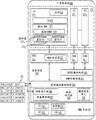
图3是根据一个实施例的图2A或者图2B的存储系统群集的用于管理虚拟卷的部件的框图。该部件包括在一个实施例中在存储系统130中执行的存储系统管理器131和132的软件模块或者在另一实施例中的分布式存储系统管理器135的软件模块、即输入/输出(I/O)管理器304、卷管理器306、容器管理器308和数据访问层310。在本文的实施例的描述中,应当理解,分布式存储系统管理器135采取的任何动作可以根据实施例由存储系统管理器131或者存储系统管理器132来采取。Figure 3 is a block diagram of components of the storage system cluster of Figure 2A or Figure 2B for managing virtual volumes, according to one embodiment. This component includes software modules of
在图3的示例中,分布式存储系统管理器135已经从DSU141创建三个存储容器SC1、SC2和SC3,示出这些存储容器中的每个存储容器具有标注为P1至Pn的纺锤体盘区。一般而言,每个存储容器具有固定物理大小并且与DSU的具体盘区关联。在图3中所示示例中,分布式存储系统管理器135具有对容器数据库316的访问,该容器数据库为每个存储容器存储它的容器ID、物理布局信息和一些元数据。容器数据库316由容器管理器308管理和更新,该容器管理器308在一个实施例中是分布式存储系统管理器135的部件。容器ID是在创建存储容器时向存储容器给定的通用唯一标识符。物理布局信息由与给定的存储容器关联并且存储为<系统ID,DSU ID,盘区编号>的有序列表的DSU141的纺锤体盘区组成。元数据分节可以包含一些公共和一些存储系统销售商专属元数据。例如,元数据分节可以包含被允许访问存储容器的计算机系统或者应用或者用户的ID。作为另一示例,元数据分节包含分配位图,该分配位图用于表示已经向现有vvol分配存储系统的哪些<系统ID,DSU ID,盘区编号>的盘区并且哪些盘区空闲。在一个实施例中,存储系统管理员可以创建用于不同业务单元的分离存储容器,从而不同业务单元的vvol不从相同存储容器调配。可以应用其它用于隔离vvol的策略。例如存储系统管理员可以采用将要从不同存储容器调配云服务的不同客户的vvol这样的策略。另外,vvol可以根据它们的所需服务水平来分组并且从存储容器来调配。此外,存储系统管理员可以创建、删除和另外管理存储容器、比如定义可以创建的存储容器的数目并且设置每存储容器可以设置的最大物理大小。In the example of FIG. 3 , distributed
另外,在图3的示例中,分布式存储系统管理器135已经(代表请求计算机系统100)而调配各自来自不同存储容器的多个vvol。一般而言,vvol可以具有固定物理大小或者可以被精简调配,并且每个vvol具有vvol ID,该vvol ID是在创建vvol时向vvol给定的通用唯一标识符。对于每个vvol,vvol数据库314为每个vvol存储它的vvol ID、其中创建vvol的存储容器的容器ID和在该存储容器内的包括vvol的地址空间的<偏移,长度>值的有序列表。vvol数据库314由卷管理器306管理和更新,该卷管理器在一个实施例中是分布式存储系统管理器135的部件。在一个实施例中,vvol数据库314也存储关于vvol的少量元数据。这一元数据在vvol数据库314中被存储为关键字-值对的集合并且可以在vvol的存在期间的任何时间经由带外路径由计算机系统100来查询。存储的关键字-值对落入三个类别。第一类别是:公知的值——某些值的定义(并且因此它们的值的解释)是公开地可用的。一个示例是与虚拟卷类型对应的关键字(例如在虚拟机实施例中,vvol是否包含VM的元数据或者VM的数据)。另一示例是App ID,该App ID是在vvol中所存储的数据的应用的ID。第二类别是:计算机系统专属关键字——计算机系统或者它的管理模块将某些关键字和值存储为虚拟卷的元数据。第三类别是:存储系统销售商专属关键字——这些允许存储系统销售商存储与虚拟卷的元数据关联的某些关键字。存储系统销售商将这一关键字-值存储用于它的元数据的一个原因在于所有这些关键字经由用于vvol的带外信道可容易地用于存储系统销售商插件和其它扩展。用于关键字-值对的存储操作是虚拟卷创建和其它过程的部分,因此存储操作应当合理地快速。存储系统也被配置使得基于与在具体关键字上提供的值的确切匹配来实现虚拟卷的搜索。Additionally, in the example of FIG. 3 , distributed
IO管理器304是维护连接数据库312的软件模块(在某些实施例中也是分布式存储系统管理器135的部件),该连接数据库312存储在PE与vvol之间的当前有效IO连接路径。在图3中所示示例中,示出七个当前有效IO会话。每个有效会话具有关联PE ID、次级标识符(SLLID)、vvol ID以及指示通过这一IO会话执行IO的不同应用的数目的参考计数(RefCnt)。分布式存储系统管理器135(例如在计算机系统100请求时)在PE与vvol之间建立有效IO会话的过程本文被称为“绑定”过程。对于每个绑定,分布式存储系统管理器135(例如经由IO管理器304)向连接数据库312添加条目。分布式存储系统管理器135随后拆除IO会话的过程本文被称为“解绑定”过程。对于每个解绑定,分布式存储系统管理器135(例如经由IO管理器304)将IO会话的参考计数递减一。在IO会话的参考计数为零时,分布式存储系统管理器135(例如经由IO管理器304)可以从连接数据库312删除用于该IO连接路径的条目。如先前讨论的那样,在一个实施例中,计算机系统100生成并且经由带外路径向分布式存储系统管理器135传输绑定和解绑定请求。备选地,计算机系统100可以通过使现有错误路径超负荷来生成解绑定请求并且经由带内路径传输解绑定请求。在一个实施例中,在参考计数从0改变成1或者相反时,将生成数改变成单调增加数或者随机生成数。在另一实施例中,生成数是随机生成的数,并且从连接数据库312消除RefCnt列,并且对于每个绑定,即使在绑定到请求是对已经绑定的vvol时,分布式存储系统管理器135仍然(例如经由IO管理器304)向连接数据库312添加条目。
在图2A的存储系统群集中,IO管理器304使用连接数据库312来处理通过PE所接收的来自计算机系统100的IO请求(IO)。当在PE中的一个PE接收IO时,IO管理器304解析IO以标识在该IO中包含的PE ID和SLLID以便确定IO被既定用于的vvol。通过访问连接数据库314,IO管理器304然后能够获取与解析的PE ID和SLLID关联的vvol ID。在图3和后续图中,为了简化而将PE ID示出为PE_A、PE_B等。在一个实施例中,实际PE ID是PE的WWN。此外,将SLLID示出为S0001、S0002等。实际SLLID由分布式存储系统管理器135生成为在与连接数据库312中的给定的PE ID关联的SLLID之中的任何唯一数。在具有vvol ID的虚拟卷的逻辑地址空间与DSU141的物理位置之间的映射由卷管理器306使用vvol数据库314并且由容器管理器308使用容器数据库316来执行。一旦已经获得DSU141的物理位置,则数据访问层310(在一个实施例中也为分布式存储系统管理器135的部件)在这些物理位置上执行IO。In the storage system cluster of FIG. 2A ,
在图2B的存储系统群集中,通过PE接收IO,并且每个这样的IO包括IO已经被发到的NFS句柄(或者相似文件系统句柄)。在一个实施例中,用于这样的系统的连接数据库312包含存储系统的NFS接口的IP地址(如PE ID)并且文件系统路径(如SLLID)。基于vvol在文件系统145中的位置而生成SLLID。在vvol的逻辑地址空间与DSU141的物理位置之间的映射由卷管理器306使用vvol数据库314并且由容器管理器308使用容器数据库316来执行。一旦已经获得DSU141的物理位置,则数据访问层在这些物理位置上执行IO。应当认识,对于图2B的存储系统,容器312可以在用于给定的vvol的容器位置条目中包含文件:<偏移.长度>条目的有序列表(即可以包括在文件系统145中存储的多个文件段的vvol)。In the storage system cluster of Figure 2B, IOs are received by PEs, and each such IO includes an NFS handle (or similar file system handle) to which the IO has been issued. In one embodiment, the
在一个实施例中,在易失性存储器中维护连接数据库312,而在永久存储、比如DSU141中维护vvol数据库314和容器数据库316。在其它实施例中,可以在永久存储中维护所有数据库312、314、316。In one embodiment,
图4是用于创建存储容器的方法步骤410的流程图。在一个实施例中,这些步骤在存储管理员的控制之下由存储系统管理器131、存储系统管理器132或者分布式存储系统管理器135来执行。如以上指出的那样,存储容器代表物理DSU的逻辑聚合并且可以跨越来自多于一个存储系统的物理DSU。在步骤411,存储管理员(经由分布式存储系统管理器135等)设置存储容器的物理容量。在云或者数据中心内,这一物理容量可以例如代表客户租赁的物理存储的数量。本文公开的存储容器所提供的灵活性在于不同客户的存储容器可以由存储管理员从相同存储系统来调配,并且例如在任何一个存储设备的物理容量不足以满足客户请求的大小的情况下或者在比如vvol的物理存储覆盖区将自然地跨越多个存储系统这样的复制的情况下用于单个客户的存储容器可以从多个存储系统来调配。在步骤412,存储管理员设置用于访问存储容器的权限级别。例如在多租户数据中心中,客户仅可以访问已经向他或者她租赁的存储容器。在步骤413,分布式存储系统管理器135生成用于存储容器的唯一标识符。然后在步骤414,分布式存储系统管理器135(例如在一个实施例中经由容器管理器308)将DSU141的空闲纺锤体盘区向存储容器分配以足够数量。如以上指出的那样,在任何一个存储系统的空闲空间不足以满足物理容量的情况下,分布式存储系统管理器135可以从多个存储系统分配DSU141的纺锤体盘区。在已经分配分区之后,分布式存储系统管理器135(例如经由容器管理器308)用唯一容器ID、<系统编号、DSU ID、盘区编号>的有序列表和被允许访问存储容器的计算机系统的上下文ID来更新容器数据库316。FIG. 4 is a flowchart of method steps 410 for creating a storage container. In one embodiment, these steps are performed by
根据本文描述的实施例,存储容量简档、例如SLA或者服务质量(QoS)可以在每vvol基础上由分布式存储系统管理器135(例如代表请求计算机系统100)来配置。因此,有可能让具有不同存储能力简档的vvol是相同存储容器的部分。在一个实施例中,系统管理员定义默认存储能力简档(或者多个可能存储能力简档),该(或者这些)存储能力简档在创建存储容器时用于新创建的vvol并且存储于容器数据库316的元数据分节中。如果未对于在存储容器以内创建的新vvol显式地指定存储能力简档,则新vvol将继承与存储容器关联的默认存储能力简档。According to embodiments described herein, a storage capacity profile, such as an SLA or quality of service (QoS), may be configured on a per-vvol basis by the distributed storage system manager 135 (eg, on behalf of the requesting computer system 100). Thus, it is possible to have vvols with different storage capability profiles be part of the same storage container. In one embodiment, the system administrator defines a default storage capability profile (or multiple possible storage capability profiles) that is used for newly created vvols when a storage container is created and stored in the container In the metadata section of the
图5A是在图2A的存储系统群集上托管的被配置用来实施虚拟卷的计算机系统的一个实施例的框图。计算机系统101可以在包括一个或者多个中央处理单元(CPU)501、存储器502、一个或者多个网络接口卡(NIC)503和一个或者多个主机总线适配器(HBA)504的通常为服务器类的常规硬件平台500上来构造。HBA504使计算机系统101能够通过在存储设备130中配置的PE来向虚拟卷发出IO。如图5A中进一步所示,在硬件平台500上面安装操作系统508,并且在操作系统508上面执行多个应用5121-512N。操作系统508的示例包括公知的商用操作系统、比如Microsoft Windows、Linux等中的任何操作系统。Figure 5A is a block diagram of one embodiment of a computer system configured to implement virtual volumes hosted on the storage system cluster of Figure 2A. Computer system 101 can be implemented on a generally server-type A conventional hardware platform 500 is built up. The
根据本文描述的实施例,每个应用512具有与之关联的一个或者多个vvol并且向操作系统508按照应用512向操作系统508中的“创建设备”调用所创建的vvol的块设备实例发出IO。在块设备数据库533中维护在块设备名称与vvol ID之间的关联。来自应用5121-512N的IO由文件系统驱动器510接收,该文件系统驱动器将它们转换成块IO并且向虚拟卷设备驱动器532提供块IO。在另一方面,示出来自应用5121的IO绕过文件系统驱动器510并且被直接提供给虚拟卷设备驱动器532,这表示应用5121以在通过引用将全部内容结合于此、名称为“Providing Access to a Raw Data Storage Unit in aComputer System”的美国专利7,155,558中描述的方式来直接访问它的块设备作为原始存储设备、例如作为数据库盘、日志盘、备份存档和内容贮存库。在虚拟卷设备驱动器532接收块IO时,它访问块设备数据库533以引用在IO中指定的块设备名称与PE ID(PE LUN的WWN)和SLLID之间的映射,该PE ID和SLLID定义通向与块设备名称关联的vvol的IO连接路径。在本文所示示例中,块设备名称archive对应于为应用5121所创建的块设备实例vvol12,并且块设备名称foo、dbase和log分别对应于为应用5122-512N中的一个或者多个应用创建的块设备实例vvol1、vvol16和vvol17。在块设备数据库533中存储的其它信息包括用于每个块设备的活跃位值和CIF(空中命令,commands-in-flight)值,该活跃位值指示块设备是否活跃。活跃位“1”表示可以向块设备发出IO。活跃位“0”表示块设备不活跃并且不能向块设备发出IO。CIF值提供有多少IO在空中(即被发出但是尚未完成)的指示。在本文所示示例中,块设备foo活跃并且具有一些空中命令。块设备archive不活跃并且不会接受更新命令。然而它等待2个空中命令完成。块设备dbase不活跃而无未完成的命令。最后,块设备log活跃,但是应用当前没有向设备的未决IO。虚拟卷设备驱动器532可以选择在任何时间从它的数据库533去除这样的设备。According to embodiments described herein, each
除了执行以上描述的映射之外,虚拟卷设备驱动器532还向数据访问层540发出原始块级IO。数据访问层540包括设备访问层534和用于HBA504的设备驱动器536,该设备访问层534将命令排队和调度策略应用于原始块级IO,并且该设备驱动器536在符合协议的格式中格式化原始块级IO并且将其向HBA504发送以用于经由带内路径而向PE转发。在其中使用SCSI协议的实施例中,在如在SAM-5(SCSI架构模型-5)中指定的SCSI LUN数据字段(该数据字段是8字节结构)中将vvol信息编码。在前2个字节中将常规用于LUN ID的PE ID编码,并且利用剩余6个字节(的部分)在SCSI第二级LUN ID中将vvol信息具体为SLLID编码。In addition to performing the mapping described above, the virtual volume device driver 532 also issues raw block-level IOs to the
如图5A中进一步所示,数据访问层540也包括用于处置通过带内路径从存储系统接收的IO错误的错误处置单元542。在一个实施例中,I/O管理器304通过PE传播错误处置单元542所接收的IO错误。IO错误类的示例包括在计算机系统101与PE之间的路径错误以及PE错误和vvol错误。该错误处置单元542将所有检测到的错误分类为前述类。在遇到通向PE的路径错误并且存在通向PE的另一路径时,数据访问层540沿着通向PE的不同路径来传输IO。在IO错误是PE错误时,错误处置单元542更新块设备数据库533以指示用于通过PE发出IO的每个块设备的错误状况。在IO错误是vvol错误时,错误处置单元542更新块设备数据库533以指示用于与vvol关联的每个块设备的错误状况。错误处置单元542也可以发出报警或者系统事件,从而将拒绝向具有错误状况的块设备的进一步发出IO。As further shown in FIG. 5A, the
图5B是图5A的计算机系统的框图,该计算机系统已经被配置以与图2B的存储系统群集而不是图2A的存储系统群集对接。在这一实施例中,数据访问层540包括NFS客户端545和用于NIC503的设备驱动器546。NFS客户端545将块设备名称映射到PE ID(NAS存储系统的IP地址)和与块设备对应的SLLID(NFS文件句柄)。如图5B中所示在块设备数据库533中存储这一映射。应当注意,虽然活跃和CIF列仍然存在,但是未在图5B中所示块设备数据库533中图示。如以下将描述的那样,NFS文件句柄在NAS存储系统内唯一标识文件对象并且可以在绑定过程期间被生成。备选地,响应于对于绑定vvol的请求,NAS存储系统返回PE ID和SLLID,并且使用普通带内机制(例如查找或者readdirplus)的vvol的开放将给予NFS文件句柄。NFS客户端545也将从虚拟卷设备驱动器532所接收的原始块级IO转译成基于NFS文件的IO。用于NIC503的设备驱动器546然后在符合协议的格式中格式化基于NFS文件的IO并且将它们与NFS句柄一起发送到NIC503用于经由带内路径向PE中的一个PE转发。5B is a block diagram of the computer system of FIG. 5A that has been configured to interface with the storage system cluster of FIG. 2B instead of the storage system cluster of FIG. 2A . In this embodiment, the
图5C是被配置以实施虚拟卷的计算机系统的另一实施例的框图。在这一实施例中,向计算机系统102配置本文示出为超管理者560的虚拟化软件。该超管理者560安装在硬件平台550上面,该硬件平台包括CPU551、存储器552、NIC553和HBA554并且支持虚拟机执行空间570,在该虚拟机执行空间内可以并行实例化和执行多个虚拟机(VM)5711-571N。在一个或者多个实施例中,使用加利福尼亚州帕罗奥图市的VMware公司分发的VMware
根据本文描述的实施例,每个VM571具有与之关联的一个或者多个vvol并且向超管理者560按照VM571向超管理者560中的“创建设备”调用所创建的vvol的块设备实例发出IO。在块设备数据库580中维护在块设备名称与vvol ID之间的关联。来自VM5712-571N的IO由SCSI虚拟化层563接收,该SCSI虚拟化层将它们转换成虚拟机文件系统(VMFS)驱动器564理解的文件IO。VMFS驱动器564然后将文件IO转换成块IO并且向虚拟卷设备驱动器565提供块IO。在另一方面,示出来自VM5711的IO绕过VMFS驱动器564并且被直接提供给虚拟卷设备驱动器565,这表示VM5711以在美国专利7,155,558中描述的方式直接访问它的块设备作为原始存储设备、例如作为数据库盘、日志盘、备份存档和内容贮存库。According to embodiments described herein, each
在虚拟卷设备驱动器565接收块IO时,它访问块设备数据库580以引用在IO中指定的块设备名称与PE ID和SLLID之间的映射,该PE ID和SLLID定义通向与块设备名称关联的vvol的IO会话。在本文所示示例中,块设备名称dbase和log分别对应于为VM5711所创建的块设备实例vvol1和vvol4,并且块设备名称vmdk2、vmdkn和snapn分别对应于为VM5712-571N中的一个或者多个VM创建的块设备实例vvol12、vvol16和vvol17。在块设备数据库580中存储的其它信息包括用于每个块设备的活跃位值和CIF(空中命令)值,该活跃位值指示块设备是否活跃。活跃位“1”表示可以向块设备发出IO。活跃位“0”表示块设备不活跃并且不能向块设备发出IO。CIF值提供有多少IO在空中(即被发出但是尚未完成)的指示。When the virtual volume device driver 565 receives a block IO, it accesses the
除了执行以上描述的映射之外,虚拟卷设备驱动器565还向数据访问层566发出原始块级IO。数据访问层566包括设备访问层567和用于HBA554的设备驱动器568,该设备访问层567将命令排队和调度策略应用于原始块级IO,并且该设备驱动器568在符合协议的格式中格式化原始块级IO并且将其向HBA554发送以用于经由带内路径而向PE转发。在其中使用SCSI协议的实施例中,在如在SAM-5(SCSI架构模型-5)中指定的SCSI LUN数据字段(该数据字段是8字节结构)中将vvol信息编码。在前2个字节中将常规用于LUN ID的PE ID编码,并且利用剩余6个字节(的部分)在SCSI第二级LUN ID中将vvol信息具体为SLLID编码。如图5C中进一步所示,数据访问层566也包括以与错误处置单元542相同的方式工作的错误处置单元569。In addition to performing the mapping described above, the virtual volume device driver 565 also issues raw block-level IOs to the
图5D是图5C的计算机系统的框图,该计算机系统已经被配置以与图2B的存储系统群集而不是图2A的存储系统群集对接。在这一实施例中,数据访问层566包括NFS客户端585和用于NIC553的设备驱动器586。NFS客户端585将块设备名称映射到PE ID(IP地址)和与块设备对应的SLLID(NFS文件句柄)。如图5D中所示在块设备数据库580中存储这一映射。应当注意,虽然活跃和CIF列仍然存在,但是未在图5D中所示块设备数据库580中图示。如以下将描述的那样,NFS文件句柄在NAS内唯一标识文件对象并且在一个实施例中在绑定过程期间被生成。NFS客户端585也将从虚拟卷设备驱动器565所接收的原始块级IO转译成基于NFS文件的IO。用于NIC553的设备驱动器586然后在符合协议的格式中格式化基于NFS文件的IO并且将它们与NFS句柄一起发送到NIC553用于经由带内路径向PE中的一个PE转发。5D is a block diagram of the computer system of FIG. 5C that has been configured to interface with the storage system cluster of FIG. 2B instead of the storage system cluster of FIG. 2A . In this embodiment,
应当认识,可以不同地引用用来描述图5A-5D中的部件的各种术语、层和分类而未脱离它们的功能或者本发明的精神实质或范围。例如VMM561可以视为在VM571与超管理者560之间的分离虚拟化部件(在这样的概念中可以本身视为虚拟化“内核”部件),因为存在有用于每个实例化的VM的分离VMM。备选地,每个VMM561可以视为它的对应虚拟机的部件,因为这样的VMM包括用于虚拟机的硬件仿真部件。在这样的备选概念中,例如描述为虚拟硬件平台573的概念层可以与VMM561合并以及合并到VMM561中,从而从图5C和5D去除虚拟主机总线适配器574(即因为它的功能由主机总线适配器仿真器562实现)。It should be appreciated that the various terms, layers and classifications used to describe the components in Figures 5A-5D may be referred to variously without departing from their functionality or the spirit or scope of the invention. For example,
图6是图示根据本发明的一个实施例的用来管理vvol的部件和通信路径的计算机环境的简化框图。如先前描述的那样,用于IO协议流量的通信路径被称为带内路径并且在图6中表示为虚线601,该虚线601(通过在计算机系统中提供的HBA或者NIC)连接计算机系统的数据访问层540与在存储系统130中配置的一个或者多个PE。用来管理vvol的通信路径是带外路径(如先前定义的那样,不是“在带内”的路径)并且在图6中表示为实线602。根据本文描述的实施例,可以通过在管理服务器610中提供的插件612和/或在计算机系统103中的每个计算机系统中提供的插件622来管理vvol,在图6中仅示出这些插件中的一个插件。在存储设备侧上,由存储系统管理器131来配置管理接口625,并且由存储系统管理器132来配置管理接口626。此外,由分布式存储系统管理器135来配置管理接口624。每个管理接口与插件612、622通信。为了有助于发出和处置管理命令,已经开发具体应用编程接口(API)。应当认识,在一个实施例中,定制两个插件612、622以与来自特定存储系统销售商的存储硬件而通信。因此,管理服务器610和计算机系统103将在与用于不同存储系统销售商的存储硬件通信时运用不同插件。在另一实施例中,可以有与任何销售商的管理接口交互的单个插件。这将需要(例如借助由计算机系统和/或管理服务器发布而)将存储系统管理器编程为公知接口。Figure 6 is a simplified block diagram illustrating a computer environment for managing components and communication paths of vvols according to one embodiment of the present invention. As previously described, the communication path for IO protocol traffic is called an in-band path and is represented in FIG. The
还向管理服务器610配置以用于管理计算机系统的系统管理器611。在一个实施例中,计算机系统执行虚拟机,并且系统管理器611管理在计算机系统中运行的虚拟机。管理虚拟机的系统管理器611的一个示例是VMware公司分发的
图7是用于使用与认证有关的API而向图2A或者图2B的存储系统群集认证计算机系统的方法步骤的流程图。这些方法步骤在计算机系统通过向存储系统传输它的安全套接字层(SSL)证书来请求认证时来发起。在步骤710,存储系统向请求认证的计算机系统发出用于认证证书的提示(例如用户名和密码)。在步骤712接收认证证书时,存储系统在步骤714将它们与存储的证书比较。如果提供正确证书,则存储系统在关键字存储库中存储认证的计算机系统的SSL证书(步骤716)。如果提供不正确证书,则存储系统忽略SSL证书并且返回适当错误消息(步骤718)。在被认证之后,计算机系统可以调用API以通过SSL链路向存储系统发出管理命令,并且存储系统使用在SSL证书中所包括的唯一上下文ID以实行某些策略、比如定义哪些计算机系统可以访问哪些存储容器。在一些实施例中,在管理对计算机系统批准的权限时使用它们的上下文ID。例如主机计算机可以被允许创建vvol、但是不可以被允许删除vvol或vvol的快照,或者主机计算机可以被允许创建vvol的快照、但是不可以被允许克隆vvol。此外,权限可以根据登录到认证的计算机系统的用户的用户级特权而变化。7 is a flowchart of method steps for authenticating a computer system to the storage system cluster of FIG. 2A or 2B using an authentication-related API. These method steps are initiated when the computer system requests authentication by transmitting its Secure Sockets Layer (SSL) certificate to the storage system. At step 710, the storage system sends a prompt for authentication credentials (eg, username and password) to the computer system requesting authentication. Upon receiving authentication credentials at step 712, the storage system compares them with stored credentials at step 714. If the correct certificate is provided, the storage system stores the SSL certificate of the authenticated computer system in the key store (step 716). If an incorrect certificate is provided, the storage system ignores the SSL certificate and returns an appropriate error message (step 718). After being authenticated, the computer system can call an API to issue management commands to the storage system over the SSL link, and the storage system uses the unique context ID included in the SSL certificate to enforce certain policies, such as defining which computer systems can access which storage container. In some embodiments, their context IDs are used in managing permissions granted to computer systems. For example, a host computer may be allowed to create a vvol but may not be allowed to delete a vvol or a snapshot of a vvol, or a host computer may be allowed to create a snapshot of a vvol but not be allowed to clone a vvol. Additionally, permissions may vary based on the user-level privileges of the user logged into the authenticated computer system.
图8是用于使用创建虚拟卷API命令来创建虚拟卷的方法步骤的流程图。在一个实施例中,在计算机系统103在步骤802从它的应用中的一个应用接收对于创建具有某个大小和存储能力简档、比如最小IOPS和平均延时的vvol的请求时,计算机系统103经由带外路径602向存储系统发出创建虚拟卷API命令。作为响应,计算机系统103在步骤804(在计算机系统103和请求应用被允许访问的并且具有用于容纳请求的足够空闲容量的存储容器之中)选择存储容器并且经由插件622向存储系统发出创建虚拟卷API命令。该API命令包括存储容器ID、vvol大小和vvol的存储能力简档。在另一实施例中,该API命令包括该应用要求存储系统与新创建的vvol来存储的关键字-值对集合。在另一实施例中,管理服务器610经由带外路径602向存储系统发出创建虚拟卷API命令(经由插件612)。8 is a flowchart of method steps for creating a virtual volume using the Create Virtual Volume API command. In one embodiment, when
在步骤806,存储系统管理器经由管理接口(管理接口624、625或者626)接收对于生成vvol的请求并且访问选择的存储容器的在容器数据库316中的元数据分节以验证包括计算机系统103和应用的请求上下文具有足够权限以在选择的存储容器中创建vvol。在一个实施例中,如果权限级别不足够,则向计算机系统103返回错误消息。如果权限级别足够,则在步骤810生成唯一vvol ID。然后在步骤812,存储系统管理器扫描容器数据库316的元数据分节中的分配位图以确定选择的存储容器的空闲分区。存储系统管理器分配选择的存储容器的足以容纳请求的vvol大小的空闲分区并且更新存储容器的在容器数据库316的元数据分节中的分配位图。存储系统管理器还用新vvol条目来更新vvol数据库314。新vvol条目包括在步骤810生成的vvol条目、新分配的存储容器盘区的有序列表和新vvol的表达为关键字-值对的元数据。然后在步骤814,存储系统管理器向计算机系统103传输vvol ID。在步骤816计算机系统103将vvol ID与请求创建vvol的应用关联。在一个实施例中,为每个应用维护一个或者多个vvol描述符文件,并且向为请求创建vvol的应用维护的vvol描述符文件中写入vvol ID。At
如图2A和2B中所示,并非所有vvol都连接到PE。未连接到PE的vvol因为未向vvol建立IO会话所以未知对应应用发出的IO。在可以向vvol发出IO之前,该vvol经历绑定过程,作为该绑定过程的结果,该vvol将被绑定到特定PE。一旦vvol被绑定到PE,则可以向vvol发出IO直至从PE解绑定vvol。As shown in Figures 2A and 2B, not all vvols are connected to PEs. The vvol not connected to the PE does not know the IO issued by the corresponding application because the IO session has not been established to the vvol. Before an IO can be issued to a vvol, the vvol goes through a binding process, as a result of which the vvol will be bound to a specific PE. Once a vvol is bound to a PE, IO can be issued to the vvol until the vvol is unbound from the PE.
在一个实施例中,计算机系统130使用绑定虚拟卷API经由带外路径602向存储系统发出绑定请求。该绑定请求标识待绑定的vvol(使用vvol ID),并且作为响应,存储系统将vvol绑定到计算机系统103经由带内路径连接到的PE。图9A是用于计算机系统经由带内路径发现它连接到的PE的方法步骤的流程图。使用标准SCSI命令REPORT_LUNS来经由带内路径发现在基于SCSI协议的存储设备中所配置的PE。使用API来经由带外路径发现在基于NFS协议的存储设备中所配置的PE。该计算机系统为每个连接的存储系统执行图9A的方法步骤。In one embodiment,
在步骤910,计算机系统确定连接的存储系统是否基于SCSI协议或者基于NFS协议。如果存储系统基于SCSI协议,则计算机系统向存储系统带内发出SCSI命令REPORT_LUNS(步骤912)。然后在步骤913,计算机系统检查来自存储系统的响应、具体为与返回的PE ID中的每个PE ID关联的PE位以在与PE有关的LUN与常规数据LUN之间区分。如果存储系统基于NFS协议,则计算机系统从插件622向管理接口(例如管理接口624、625或者626)带外发出API调用以获得可用PE的ID(步骤914)。在跟随步骤913和914的步骤916,计算机系统存储由存储系统所返回的与PE有关的LUN的PE ID或者由管理接口所返回的PE ID用于在绑定过程期间使用。应当认识,基于SCSI协议的存储设备所返回的PE ID各自包括WWN,并且基于NFS协议的存储设备所返回的PE ID各自包括IP地址和挂载点。In step 910, the computer system determines whether the connected storage system is based on SCSI protocol or NFS protocol. If the storage system is based on the SCSI protocol, the computer system sends the SCSI command REPORT_LUNS to the storage system in-band (step 912 ). Then at
图9B是用于存储系统管理器131或者存储系统管理器132或者分布式存储系统管理器135(下文称为“存储系统管理器”)发现给定的计算机系统103经由带内路径连接到的PE的方法步骤的流程图。存储系统管理器发现这样的PE使存储系统能够响应于来自请求计算机系统的绑定请求而向计算机系统返回计算机系统可以被实际连接到其上的有效PE ID。在步骤950,存储系统管理器经由管理接口和插件622向计算机系统103发出带外“Discovery_Topology(发现_拓扑)”API调用。计算机系统103返回它的系统ID和它经由图9A的流程图所发现的所有PE ID的列表。在一个实施例中,存储系统管理器通过经由管理接口和插件612向管理服务器610发出“Discovery_Topology”API调用来执行步骤950。在这样的实施例中,存储系统将接收响应,该响应包含多个计算机系统ID和关联PEID,每个计算机系统ID和关联PE ID用于管理服务器610管理的一计算机系统103。然后在步骤952,存储系统管理器处理来自步骤950的结果。例如存储系统管理器清除未在它的当前控制之下的所有PEID的列表。例如存储系统管理器135在发出Discovery_Topology调用时所接收的某些PE ID可以对应于连接到相同计算机系统的另一存储系统。相似地,某些接收的PE ID可以对应于自从被存储系统管理员删除而起的更旧PE等。在步骤954,存储系统管理器将处理的结果高速缓存用于在后续绑定请求过程期间使用。在一个实施例中,存储系统管理器周期性地运行图9B的步骤以用进行中的计算机系统和网络拓扑改变来更新它的高速缓存的结果。在另一实施例中,存储系统管理器每当它接收新vvol创建请求时运行图9B的步骤。在又一实施例中,存储系统管理器在运行图7的认证步骤之后运行图9B的步骤。9B is used for the
图10是用于使用绑定虚拟卷API来发出和执行虚拟卷绑定请求的方法步骤的流程图。在一个实施例中,计算机系统103在它的应用中的一个应用请求IO访问与尚未绑定到PE的vvol关联的块设备时经由带外路径602向存储系统发出绑定请求。在另一实施例中,管理服务器610结合某些VM管理操作而发出绑定请求,这些VM管理操作包括VM通电和从一个存储容器向另一存储容器的vvol迁移。10 is a flowchart of method steps for issuing and executing a virtual volume bind request using the bind virtual volume API. In one embodiment, the
继续以上描述的示例,在该示例中,应用请求IO访问与尚未绑定到PE的vvol关联的块设备,计算机系统103在步骤1002从块设备数据库533(或者580)确定vvol的vvol ID。然后在步骤1004,计算机系统1003通过带外路径602向计算机系统发出对于绑定vvol的请求。Continuing with the example described above, in which an application requests IO access to a block device associated with a vvol not yet bound to a PE,
存储系统管理器在步骤1006经由管理接口(例如管理接口624、625或者626)接收对于绑定vvol的请求、然后执行步骤1008,该步骤包括选择vvol将被绑定到的PE、生成用于所选择的PE的SLLID和生成数并且更新连接数据库312(例如经由IO管理器304)。vvol将要被绑定到的PE的选择根据连通性和其他因素比如通过可用PE的当前IO流量来进行、即仅仅具有与计算机系统103的现有带内连接的PE才可用于选择。在一个实施例中,存储系统根据图9B的方法从计算机系统103向它发送的处理和高速缓存的PE列表来选择。SLLID生成在运用图2A的存储系统群集的实施例与运用图2B的存储系统群集的实施例之间不同。在前一情况下,生成对于选择的PE唯一的SLLID。在后一情况下,生成通向与vvol对应的文件对象的文件路径作为SLLID。在已经对于选择的PE生成SLLID和生成数之后,更新连接数据库312以包括对vvol的新生成的IO会话。然后在步骤1010,向计算机系统103返回选择的PE的ID、生成的SLLID和生成数。可选地,在运用图2B的存储系统群集的实施例中,可以对于与vvol对应的文件对象而生成唯一NFS文件句柄并且将其与选择的PE的ID、生成的SLLID和生成数一起向计算机系统103返回。在步骤1012,计算机系统103更新块设备数据库533(或者580)以包括从存储系统返回的PE ID、SLLID(以及可选地NFS句柄)和生成数。具体而言,将向块设备数据库533(或者580)添加从存储系统返回的PE ID、SLLID(以及可选地NFS句柄)和生成数的每个集合作为新条目。应当认识,生成数用来防范重放攻击。因此,在其中未考虑重放攻击的实施例中,未使用生成数。The storage system manager receives a request to bind the vvol via a management interface (such as
在期望向相同vvol发出IO的不同应用所发起的向相同vvol的绑定请求后,存储系统管理器可以将vvol绑定到相同或者不同PE。如果将vvol绑定到相同PE,则存储系统管理器返回相同PE的ID和先前生成的SLLID并且增加在连接数据库312中所存储的这一IO连接路径的参考计数。在另一方面,如果将vvol绑定到不同PE,则存储系统管理器生成新SLLID并且返回该不同PE的ID和新生成的SLLID并且向连接数据库312添加对vvol的这一新IO连接路径作为新条目。After binding requests to the same vvol initiated by different applications that desire to issue IO to the same vvol, the storage system manager can bind the vvol to the same or different PEs. If the vvol is bound to the same PE, the storage system manager returns the ID of the same PE and the previously generated SLLID and increments the reference count of this IO connection path stored in the
可以使用解绑定虚拟卷API来发出虚拟卷解绑定请求。解绑定请求包括先前已经通过其绑定vvol的IO连接路径的PE ID和SLLID。然而建议解绑定请求的处理。存储系统管理器立即或者在延迟之后自由地从PE解绑定vvol。通过更新连接数据库312以减少包含PE ID和SLLID的条目的参考计数来处理解绑定请求。如果将参考计数递减至零,则可以删除条目。在这一情况下应当注意,vvol继续存在、但是不再可用于使用给定的PE ID和SLLID的IO。A virtual volume unbind request can be issued using the unbind virtual volume API. The unbind request includes the PE ID and SLLID of the IO connection path through which the vvol has previously been bound. However, the handling of unbind requests is recommended. The storage system manager is free to unbind the vvol from the PE either immediately or after a delay. The unbind request is handled by updating the
在实施VM的虚拟盘的vvol的情况下,用于这一vvol的参考计数将至少为一。在使VM断电并且与之结合发出解绑定请求时,参考计数将被递减一。如果参考计数为零,则可以从连接数据库312去除vvol条目。一般而言,从连接数据库312去除条目是有益的,因为I/O管理器304管理更少数据并且也可以回收SLLID。这样的益处在存储系统所存储的vvol总数大(例如vvol数以百万计级)、但是应用活跃地访问的vvol总数小(例如VM数以万计)时变得显著。此外,在vvol未被绑定到任何PE时,存储系统在选择在DSU141中何处存储vvol时具有更大灵活性。例如可以用不对称、分级DSU141来实施存储系统,其中一些DSU141提供更快数据访问并且其它DSU141提供更慢数据访问(例如以节省存储成本)。在一个实现方式中,在vvol未被绑定到任何PE(这可以通过检查vvol的在连接数据库312中的条目参考计数来确定)时,存储系统可以向更慢和/或更廉价类型的物理存储迁移vvol。然后,一旦将vvol绑定到PE,则存储系统可以向更快类型的物理存储来迁移vvol。应当认识,可以通过改变vvol数据库314中的组成给定的vvol的容器位置的有序列表的一个或者多个元素并且更新容器数据库316的元数据分节中的对应盘区分配位图来实现这样的迁移。In the case of a vvol implementing a VM's virtual disk, the reference count for this vvol will be at least one. When a VM is powered off and an unbind request is issued in conjunction with it, the reference count will be decremented by one. If the reference count is zero, the vvol entry may be removed from
向PE绑定和解绑定vvol使存储系统管理器能够确定vvol活性。存储系统管理器可以利用这一信息以对非IO服务(非活跃)和IO服务(活跃)vvol来执行存储系统销售商专属优化。例如,存储系统管理器可以被配置以如果vvol保持在非活跃状态中超出特定阈值时间则将它从低延时(高成本)SSD重新定位到中延时(低成本)硬驱动。Binding and unbinding vvols to PEs enables the storage system manager to determine vvol activity. The storage system manager can use this information to perform storage system vendor-specific optimizations on non-IO service (inactive) and IO service (active) vvols. For example, the storage system manager may be configured to relocate a vvol from a low-latency (high cost) SSD to a mid-latency (low cost) hard drive if it remains inactive for longer than a certain threshold time.
图11A和11B是根据一个实施例的用于向虚拟卷发出IO的方法步骤的流程图。图11A是用于从应用向原始块设备直接发出IO的方法步骤1100的流程图,并且图11B是用于从应用通过文件系统驱动器发出IO的方法步骤1120的流程图。11A and 11B are a flowchart of method steps for issuing IOs to a virtual volume, according to one embodiment. FIG. 11A is a flowchart of
方法1100在步骤1102开始,其中应用、比如图5A-5B中所示应用512或者图5C-5D中所示VM571向原始块设备发出IO。在步骤1104,虚拟卷设备驱动器532或者565根据该应用所发出的IO来生成原始块级IO。在步骤1106,原始块设备的名称由虚拟卷设备驱动器532或者565转译成PE ID和SLLID(并且在运用图2B的存储设备的实施例中也由NFS客户端545或者585转译成NFS句柄)。在步骤1108,数据访问层540或者566执行将PE ID和SLLID(并且在运用图2B的存储设备的实施例中也将NFS句柄)编码成原始块级IO。然后在步骤1110,HBA/NIC发出原始块级IO。
对于非VM应用、比如图5A-5B中所示应用512,方法1120在步骤1121开始。在步骤1121,应用向在基于vvol的块设备上所存储的文件发出IO。然后在步骤1122,文件系统驱动器、例如文件系统驱动器510根据文件IO来生成块级IO。在步骤1122之后,执行与步骤1106、1108和1110相同的步骤1126、1128和1130。For non-VM applications, such as
对于VM应用、比如图5C-5D中所示VM571,方法1120在步骤1123开始。在步骤1123,VM向它的虚拟盘发出IO。然后在步骤1124,这一IO例如由SCSI虚拟化层563转译成文件IO。文件系统驱动器、例如VMFS驱动器564然后在步骤1125根据文件IO来生成块级IO。在步骤1125之后,执行与步骤1106、1108和1110相同的步骤1126、1128和1130。For a VM application, such as
图12是根据一个实施例的用于在存储系统执行IO的方法步骤的流程图。在步骤1210,通过在存储系统中所配置的PE中的一个PE来接收计算机系统发出的IO。IO管理器304在步骤1212解析该IO。在步骤1212之后,如果存储系统群集是图2A中所示类型,则IO管理器304执行步骤1214a,并且如果存储系统群集是图2B中所示类型,则IO管理器304执行步骤1214b。在步骤1214a,IO管理器304从解析的IO提取SLLID并且访问连接数据库312以确定与PE ID和提取的SLLID所对应的vvol ID。在步骤1214b,IO管理器304从解析的IO提取NFS句柄并且使用PE ID和该NFS句柄将vvol标识为SLLID。在步骤1214a和步骤1214b之后执行步骤1216。在步骤1216,卷管理器306和容器管理器308分别访问vvol数据库314和容器数据库316以获得将要对其执行IO的物理存储位置。然后在步骤1218,数据访问层310在步骤1216所获得的物理存储位置上来执行IO。Figure 12 is a flowchart of method steps for performing IO at a storage system, according to one embodiment. In
在一些情形中,应用(应用512或者VM571)、管理服务器610和/或存储系统管理器可以确定vvol到特定PE的绑定比如在PE由于太多绑定而变成超负荷时正在经历问题。作为一种解决这样的问题的方式,即使在IO命令被引向vvol时,存储系统管理器仍然可以将绑定的vvol重新绑定到不同PE。图13是根据一个实施例的用于使用重新绑定API来发出和执行vvol重新绑定请求的方法步骤1300的流程图。In some cases, an application (
如图所示,方法1300在步骤1302开始,其中存储系统管理器确定应当将vvol绑定到与vvol当前被绑定到的第一PE不同的第二PE。在步骤1304,存储系统管理器经由带外路径而向计算机系统(例如计算机系统103)发出请求以重新绑定vvol,该计算机系统运行向vvol发出IO的应用。在步骤1306,计算机系统103从存储系统管理器接收重新绑定请求并且作为响应发出请求以将vvol绑定到新PE。在步骤1308,存储系统管理器接收重新绑定请求并且作为响应将vvol绑定到新PE。在步骤1310,存储系统管理器如以上结合图10描述的那样向计算机系统传输vvol现在也被绑定到的新PE的ID和SLLID以访问vvol。As shown,
在步骤1312,计算机系统从存储系统管理器接收新PE ID和SLLID。在块设备数据库533或者580中,初始地将新PE连接的活跃位设置成1,这意味着已经建立经由新PE的用于vvol的新IO会话。计算机系统也将第一PE连接的活跃位设置成0,这表示不能通过这一PE连接而向vvol发出更多IO。应当认识,不应在去激活时立即解绑定这一PE连接,因为可能有通过这一PE连接的向vvol的IO可能在空中、即被发出但是尚未完成。因此,在步骤1314,计算机系统访问块设备数据库533或者580以查看是否已经完成通过第一PE连接而向vvol发出的所有“空中命令”(CIF)、即是否CIF=0。计算机系统在执行步骤1318之前等待CIF变成零。同时,因为已经将新PE连接的活跃位设置成1,所以通过新PE发出向vvol的附加IO。在CIF达到零时,执行步骤1318,其中向存储系统管理器发出用于解绑定第一PE连接的请求。然后在步骤1320,存储系统管理器从第一PE解绑定vvol。另外,计算机系统在步骤1324通过新PE向vvol发出所有附加IO。At
图14是根据一个实施例的虚拟卷的生命周期的概念图。图14中所示所有命令、即创建、快照、克隆、绑定、解绑定、扩展和删除形成vvol管理命令集并且通过以上结合图6描述的插件612、622可访问。如图所示,在将vvol生成为以下命令——创建vvol、快照vvol或者克隆vvol——中的任何命令的结果时,生成的vvol保持在“非活跃”状态中,其中vvol未被绑定到特定PE、因此不能接收IO。此外,在vvol在非活跃状态中时执行以下命令——快照vvol、克隆vvol或者扩展vvol——中的任何命令时,原有vvol和新创建的vvol(如果有)保持在非活跃状态中。也如图所示,当在非活跃状态中的vvol被绑定到PE时,vvol进入“活跃”状态。反言之,在从PE解绑定活跃vvol时,vvol进入非活跃状态,这假设vvol未被绑定到任何附加PE。当vvol在活跃状态中时执行以下命令——快照vvol、克隆vvol、扩展vvol或者重新绑定vvol——中的任何命令时,原有vvol保持在活跃状态中,并且新创建的vvol(如果有)保持在非活跃状态中。Figure 14 is a conceptual diagram of the lifecycle of a virtual volume, according to one embodiment. All the commands shown in FIG. 14, namely create, snapshot, clone, bind, unbind, extend and delete form the vvol management command set and are accessible through the plug-
如以上描述的那样,VM可以具有多个虚拟盘,并且为每个虚拟盘创建分离vvol。VM也具有描述VM的配置的元数据文件。元数据文件包括VM配置文件、VM日志文件、盘描述符文件、VM交换文件等。每个盘描述符文件用于VM的虚拟盘中的每个相应虚拟盘。用于虚拟盘的盘描述符文件包含涉及虚拟盘的信息、比如它的vvol ID、它的大小、该虚拟盘是否被精简调配以及为虚拟盘创建的一个或者多个快照的标识等。VM交换文件在存储系统上提供VM的交换空间。在一个实施例中,在vvol中存储这些VM配置文件,并且这一vvol本文被称为元数据vvol。As described above, a VM can have multiple virtual disks and a separate vvol is created for each virtual disk. VMs also have metadata files that describe the configuration of the VM. Metadata files include VM configuration files, VM log files, disk descriptor files, VM swap files, and the like. Each disk descriptor file is for each corresponding one of the VM's virtual disks. A disk descriptor file for a virtual disk contains information about the virtual disk, such as its vvol ID, its size, whether the virtual disk is thin-provisioned, and the identification of one or more snapshots created for the virtual disk. VM swap files provide swap space for VMs on the storage system. In one embodiment, these VM configuration files are stored in a vvol, and this vvol is referred to herein as a metadata vvol.
图15是根据一个实施例的用于调配VM的方法步骤的流程图。在这一实施例中,使用管理服务器610、托管VM的计算机系统例如图5C中所示计算机102(下文称为“主机计算机”)以及图2A的存储系统群集具体为存储系统管理器131、132或者135。如图所示,存储系统管理器在步骤1502接收用于调配VM的请求。这可以是在VM管理员使用至管理服务器610的适当用户接口而向管理服务器610发出用于调配具有某个大小和存储能力简档的VM的命令时所生成的请求。响应于该命令,在步骤1504,管理服务器610发起用于用以上结合图8描述的方式来创建用于包含VM的元数据的vvol(下文称为“元数据vvol”)的方法,按照该方法存储系统管理器在步骤1508创建元数据vvol并且向管理服务器610返回元数据vvol的vvol ID。在步骤1514,管理服务器610向托管VM的计算机系统注册返回元数据vvol的vvol ID。在步骤1516,主机计算机发起用于用以上结合图10描述的方式而将元数据vvol绑定到PE的方法,按照该方法存储系统管理器在步骤1518将元数据vvol绑定到PE并且向主机计算机返回PE ID和SLLID。Figure 15 is a flowchart of method steps for provisioning a VM, according to one embodiment. In this embodiment, using a
在步骤1522,主机计算机使用“创建设备”调用来在主机计算机的操作系统中创建元数据vvol的块设备实例。然后在步骤1524,主机计算机在块设备上创建文件系统(例如VMFS),响应于这一点而返回文件系统ID(FSID)。主机计算机在步骤1526挂载具有返回的FSID的文件系统并且向与这一文件系统关联的命名空间中存储VM的元数据。元数据的示例包括VM日志文件、盘描述符文件和VM交换文件,每个盘描述符文件用于VM的虚拟盘中的每个相应虚拟盘。At
在步骤1528,主机计算机发起用于用以上结合图8描述的方式来为VM的虚拟盘中的每个虚拟盘创建vvol(每个这样的vvol本文被称为“数据vvol”)的方法,按照该方法存储系统管理器在步骤1530创建数据vvol并且向主机计算机返回数据vvol的vvol ID。在步骤1532,主机计算机在用于虚拟盘的盘描述符文件中存储数据vvol的ID。该方法以在已经为VM的所有虚拟盘创建数据vvol之后而将元数据vvol解绑定(未示出)作为结束。At
图16A是用于在已经以结合图15描述的方式来调配VM之后用于使VM通电的方法步骤的流程图。图16B是在已经使VM通电之后用于使VM断电的方法步骤的流程图。这两种方法由用于VM的主机计算机来执行。16A is a flowchart of method steps for powering on a VM after it has been provisioned in the manner described in connection with FIG. 15 . 16B is a flowchart of method steps for powering off a VM after the VM has been powered on. Both methods are performed by the host computer for the VM.
在步骤1608接收VM通电命令时,在步骤1610获取与VM对应的元数据vvol。然后在步骤1612,元数据vvol经历如以上结合图10描述的绑定过程。在步骤1614在元数据vvol上挂载文件系统,从而可以在步骤1616读取用于数据vvol的元数据文件、具体为盘描述符文件并且获得数据vvol ID。数据vvol然后在步骤1618逐个经历如以上结合图10描述的绑定过程。When a VM power-on command is received at
在步骤1620接收VM断电命令时,在块设备数据库(例如图5C的块设备数据库580)将VM的数据vvol标记为不活跃,并且主机计算机等待与数据vvol中的每个数据vvol关联的CIF达到零(步骤1622)。在与每个数据vvol关联的CIF达到零时,主机计算机在步骤1624请求存储系统解绑定该数据vvol。在与所有数据vvol关联的CIF都达到零之后,在步骤1626在块设备数据库中将元数据标记为不活跃。然后在步骤1628,在与元数据vvol关联的CIF达到零时,主机计算机在步骤1630请求将元数据vvol解绑定。Upon receipt of the VM power off command at
图17和18是用于重新调配VM的方法步骤的流程图。在本文所图示示例中,图17是用于扩展VM的vvol、具体为用于VM的虚拟盘的数据vvol的大小的在主机计算机上执行的方法步骤的流程图,并且图18是用于在存储容器之间移动VM的vvol的在存储系统中执行的方法步骤的流程图。17 and 18 are flowcharts of method steps for re-provisioning a VM. In the example illustrated herein, FIG. 17 is a flowchart of method steps performed on a host computer for extending the size of a vvol of a VM, specifically a data vvol for a virtual disk of a VM, and FIG. A flowchart of method steps performed in a storage system for moving vvols of a VM between storage containers.
用于扩展用于VM的虚拟盘的数据vvol的大小的方法在步骤1708开始,其中主机计算机确定是否使VM通电。如果主机计算机在步骤1708确定未使VM通电,则主机计算机在步骤1710获取与VM对应的元数据vvol的ID。然后,主机计算机在步骤1712发起用于元数据vvol的绑定过程。在绑定之后,在步骤1714,主机计算机在元数据vvol上挂载文件系统并且从用于虚拟盘的盘描述符文件获取与虚拟盘对应的数据vvol的ID,该盘描述符文件是在元数据vvol上挂载的文件系统中的文件。然后在步骤1716,主机计算机在步骤1716向存储系统发送扩展vvol API调用,其中扩展vvol API调用包括数据vvol的ID和新的数据vvol的大小。The method for extending the size of a data vvol of a virtual disk for a VM begins at
如果使VM通电,则主机计算机在步骤1715获取VM的待扩展的虚拟盘的数据vvol的ID。应当从图16A的方法认识,可以从与VM的虚拟盘关联的盘描述符文件获得这一ID。然后在步骤1716,主机计算机在步骤1716向存储系统发送扩展vvol API调用,其中扩展vvol API调用包括数据vvol的ID和新的数据vvol的大小。If the VM is powered on, the host computer obtains at
扩展vvol API调用造成在存储系统中更新vvol数据库和容器数据库(例如图3的vvol数据库314和容器数据库316)以反映vvol的增加的地址空间。在接收扩展vvol API调用已经完成的确认时,主机计算机在步骤1718用新的大小更新用于VM的虚拟盘的盘描述符文件。然后在步骤1720,主机计算机确定是否使VM通电。如果不使VM通电,则主机计算机在步骤1722卸载文件系统并且向存储系统发送用于解绑定元数据vvol的请求。在另一方面,如果使VM通电,则该方法终止。The extended vvol API calls cause the vvol database and container database (eg,
用于将VM的当前绑定到PE的vvol从源存储容器移向目的存储容器(其中源存储容器和目的存储容器二者在相同存储系统管理器的范围内)的方法在步骤1810开始,其中接收源存储容器和目的存储容器的容器ID(分别为SC1和SC2)以及待移动的vvol的vvolID。然后在步骤1812,更新vvol数据库(例如图3的vvol数据库314)和容器数据库(例如图3的容器数据库316)的盘区分配位图如下。首先,存储系统管理器从SC1的在容器数据库316中的条目去除SC1中的vvol盘区、然后通过修改SC2的在容器数据库316中的条目来向SC2指派这些盘区。在一个实施例中,存储系统可以通过向SC1指派新纺锤体盘区来补偿SC1中的(由于去除vvol存储盘区的)存储容量损失并且通过从SC2去除一些未使用的纺锤体盘区来弥补SC2中的(由于添加vvol存储盘区的)存储容量增加。在步骤1814,存储系统管理器确定当前绑定的PE是否能够最优地服务于向vvol的新位置的IO。在当前PE不能服务于向vvol的新位置的IO的示例实例是如果存储管理员已经静态配置存储系统管理器以向来自不同客户并且因此来自不同存储容器的vvol指派不同PE。如果当前PE不能服务于向vvol的IO,则vvol在步骤1815经历以上结合图13描述的重新绑定过程(和对连接数据库、例如图3的连接数据库312的关联改变)。在步骤1815之后,执行步骤1816,其中向主机计算机返回成功移动完成的确认。如果存储系统管理器在步骤1814确定当前PE能够服务于向vvol的新位置的IO,则绕过步骤1815并且接着执行步骤1816。The method for moving a vvol of a VM currently bound to a PE from a source storage container to a destination storage container (where both the source storage container and the destination storage container are within range of the same storage system manager) begins at
当在不兼容存储容器之间、例如在不同制造商的存储设备中所创建的存储容器之间移动vvol时,除了对容器数据库316、vvol数据库314和连接数据库312的改变之外还在存储容器之间执行数据移动。在一个实施例中,运用在通过引用将全部内容结合于此、提交于2008年5月29日并且名称为“Offloading Storage Operations toStorage Hardware”的第12/129,323号美国专利申请中所描述的数据移动技术。When moving vvols between incompatible storage containers, such as storage containers created in different manufacturers' storage devices, in addition to changes to the
图19是用于从模板VM克隆VM的在主机计算机和存储系统中执行的方法步骤的流程图。这一方法在步骤1908开始,其中主机计算机向存储系统发送请求以给新VM创建元数据vvol。在1910,存储系统根据以上结合图8描述的方法给新VM创建元数据并且向主机计算机返回新元数据vvol ID。然后在步骤1914,对于属于模板VM的所有数据vvol ID从主机计算机经由带外路径601向存储系统发出克隆vvol API调用。在步骤1918,存储系统管理器检查以查看模板VM和新VM的数据vvol是否兼容。应当认识,如果克隆在不同制造商的存储系统中所创建的存储容器之间出现,则数据vvol不可能兼容。如果有兼容性,则执行步骤1919。在步骤1919,存储系统管理器通过生成新数据vvol ID、更新容器数据库316中的分配位图并且向vvol数据库314添加新vvol条目来创建新数据vvol,以及向新VM的数据vvol复制在模板VM的数据vvol中所存储的内容。在步骤1920,存储系统管理器向主机计算机返回新数据vvol ID。接收新数据vvol ID向主机计算机提供数据vvol克隆完成而无错误的确认。然后在步骤1925,主机计算机向新VM的元数据vvol发出IO以用新生成的数据vvol ID来更新元数据文件、具体为盘描述符文件。存储系统在步骤1926执行主机计算机向存储系统发出的IO,作为其结果,用新生成的数据vvol ID来更新新VM的盘描述符文件。19 is a flowchart of method steps performed in a host computer and storage system for cloning a VM from a template VM. The method begins at
如果存储系统管理器在步骤1918确定模板VM和新VM的数据vvol不兼容,则向主机计算机返回错误消息。在接收这一错误消息时,主机计算机在步骤1921向存储系统发出创建vvol API调用以创建新数据vvol。在步骤1922,存储系统管理器通过生成新数据vvolID、更新容器数据库316中的分配位图并且向vvol数据库314添加新vvol条目来创建新数据vvol并且向主机计算机返回新数据vvolID。在步骤1923,主机计算机根据在通过引用将全部内容结合于此、提交于2009年1月21日并且名称为“Data Mover for ComputerSystem”的第12/356,694号美国专利申请中描述的技术来执行数据移动(步骤1923)。在步骤1923之后,如以上描述的那样来执行步骤1925和1926。If the storage system manager determines at
图20是根据另一实施例的用于调配VM的方法步骤的流程图。在这一实施例中,使用管理服务器610、托管VM的计算机系统例如图5D中所示计算机系统102(下文称为“主机计算机”)以及图2B的存储系统群集具体为存储系统管理器131或者存储系统管理器132或者存储系统管理器135。如图所示,在步骤2002接收用于调配VM的请求。这可以是在使用与管理服务器610的适当用户接口的VM管理员向管理服务器610发出用于调配具有某个大小和存储能力简档的VM的命令时所生成的请求。响应于该命令,在步骤2004,管理服务器610发起用于用以上结合图8描述的方式来创建包含VM的元数据的vvol、具体为元数据vvol的方法,按照该方法存储系统管理器在步骤2008创建元数据vvol(该元数据vvol是在NAS设备中的文件)并且向管理服务器610返回元数据vvol ID。在步骤2020,管理服务器610注册向主机计算机系统返回的元数据vvol的vvol ID。在步骤2022,主机计算机向存储系统发出对于元数据vvolID的请求,响应于该请求,存储系统在步骤2023分别返回IP地址和目录路径作为PE ID和SLLID。在步骤2024,主机计算机在指定的IP地址和目录路径挂载目录并且在挂载的目录中存储元数据文件。在使用NFS的实施例中,NFS客户端545或者585可以将给定的IP地址和目录路径分解成NFS句柄以便向这样的目录发出NFS请求。Figure 20 is a flowchart of method steps for provisioning a VM, according to another embodiment. In this embodiment, using the
在步骤2026,主机计算机发起用于用以上结合图8描述的方式为VM的虚拟盘中的每个虚拟盘创建数据vvol的方法,按照该方法存储系统管理器在步骤2030创建数据vvol并且向主机计算机返回数据vvol的vvol ID。在步骤2032,主机计算机在用于虚拟盘的盘描述符文件中存储数据vvol的ID。该方法以在已经对于VM的所有虚拟盘创建数据vvol之后而将元数据vvol解绑定(未示出)作为结束。At
如以上结合图8描述的那样,在从存储容器创建新vvol并且未为新vvol显式地指定存储能力简档时,新vvol将继承与存储容器关联的存储能力简档。可以从若干不同简档中的一个简档选择与存储容器关联的存储能力简档。例如,如图21中所示,不同简档包括生产(prod)简档2101、开发(dev)简档2102和测试简档2103(本文通称为“简档2100”)。应当认识,可以定义许多其它简档。如图所示,特定简档的每个简档条目为固定类型或者可变类型并且具有名称和与它关联的一个或者多个值。固定类型的简档条目具有固定数目的可选择项目。例如可以将简档条目“复制”设置成真或者假。对照而言,可变类型的简档条目没有预定义选择。相反,为可变类型的简档条目设置默认值和值范围,并且用户可以在范围内选择任何值。如果未指定值,则使用默认值。在图21中所示示例简档2100中,可变类型的简档条目具有被逗号分离的三个数。第一个数是指定的范围的更低端,并且第二个数是指定的范围的更高端。第三个数是默认值。因此,继承在生产简档2101中所定义的存储能力简档的vvol将被复制(复制.值=真),并且可以在范围0.1到24小时中定义用于该复制的恢复时间目标(RTO),默认为1小时。此外,将快照允许用于这一vvol(复制.值=真)。保持的快照数目在范围1至100中,默认为1,并且快照频率在范围每小时一次至每24小时一次中,默认为每小时一次。快继承(SnapInherit)列指示在将给定的vvol快照以创建作为衍生vvol的新vvol时是否应当向衍生vvol传播给定的简档属性(及其值)。在生产简档2101的示例中,可以用生产简档2101向给定的vvol的快照vvol传播仅前两个简档条目(复制和RTO)。快照vvol的所有其它属性的值将被设置成在简档中指定的默认值。换言之,这些其它属性在给定的vvol上的任何定制(例如快照频率的非默认值)将由于它们的对应SnapInherit列为假而不会向快照vvol传播。该简档也包含其它列、比如CloneInherit(未示出)和ReplicaInherit(未示出),这两列控制分别向给定的vvol的克隆和复制去传播哪些属性值。As described above in connection with FIG. 8, when a new vvol is created from a storage container and no storage capability profile is explicitly specified for the new vvol, the new vvol will inherit the storage capability profile associated with the storage container. The storage capability profile associated with the storage container can be selected from one of several different profiles. For example, as shown in Figure 21, the different profiles include a production (prod) profile 2101, a development (dev) profile 2102, and a test profile 2103 (collectively referred to herein as "
在根据图4的方法创建存储容器时,可以设置能力简档类型的类型,该能力简档类型可以被定义用于根据存储容器所创建的vvol。图21中的流程图图示图4中所示用于创建存储容器的方法而在步骤412与413之间插入步骤2110。在步骤2110,存储管理员选择用于创建存储容器的简档2100中的一个或者多个简档。例如为一个客户所创建的存储容器可以与生产简档2101和开发简档2102关联,使得生产类型的vvol能够如情况可以是的那样来继承用默认值或者客户指定的值而在生产简档2101中定义的存储能力简档,并且使得开发类型的vvol能够如情况可以是那样来继承用默认值或者客户指定的值而在开发简档2102中定义的存储能力简档。When creating a storage container according to the method in FIG. 4 , a type of a capability profile type can be set, and the capability profile type can be defined for a vvol created according to the storage container. The flowchart in FIG. 21 illustrates the method shown in FIG. 4 for creating a storage container with a
图22是图示用于创建vvol并且定义用于vvol的存储能力简档的由存储系统管理器131、132或者135所执行的方法步骤的流程图。图22的方法步骤、具体为步骤2210、2212、2218和2220分别对应于图8中所示步骤806、810、812和814。此外,图22的方法步骤包括步骤2214、2215和2216,这些步骤定义用于创建的vvol的存储能力简档。Figure 22 is a flowchart illustrating method steps performed by a
在步骤2214,存储系统管理器确定是否已经在用于创建vvol的请求中指定将在存储能力简档中使用的值。如果它们不是,则存储系统管理器在步骤2215运用与vvol的存储容器关联的存储能力简档作为vvol的具有默认值的存储能力简档。如果已经指定在存储能力简档中使用的值,则存储系统管理器在步骤2216运用与vvol的存储容器关联的存储能力简档作为vvol的具有指定的值而不是默认值的存储能力简档。In
在一个实施例中,将vvol的存储能力简档在vvol数据库314中存储为关键字-值对。一旦已经定义vvol的存储能力简档并且将vvol的存储能力简档在vvol数据库314中存储为关键字-值对,并且只要与复制和快照有关的属性和值是如图21的示例简档中所示的这一简档的部分,则存储系统就能够执行用于vvol的复制和快照而无由主机计算机发出的进一步指令。In one embodiment, the vvol's storage capability profile is stored in the
图23是图示用于从母vvol创建快照的由存储系统管理器131、132或者135执行的方法步骤的流程图。在一个实施例中,运用快照跟踪数据结构以根据在给定vvol的存储能力简档中的快照定义来调度快照。在达到用于快照的调度时间时,存储系统管理器在步骤2310从快照跟踪数据结构获取vvol ID。然后在步骤2312,存储系统管理器生成用于快照的唯一vvol ID。该存储系统管理器在步骤2315运用母vvol(即具有从快照跟踪数据结构获取的vvol ID的vvol)的存储能力简档作为快照vvol的存储能力简档。应当注意,由于这是存储系统所驱动的自动化简档驱动快照过程,所以用户未获得将要在快照vvol的存储能力简档中使用的指定定制值的机会。在步骤2318,存储系统管理器通过更新容器数据库316中的分配位图并且向vvol数据库314添加用于快照vvol的新vvol条目而在母vvol的存储容器内创建快照vvol。然后在步骤2320,存储系统管理器通过调度用于生成用于母vvol的下一快照的时间来更新快照跟踪数据结构。应当认识,存储系统管理器必须对于所有如下vvol并行维护快照跟踪数据结构并且执行图23的方法步骤,这些vvol的存储能力简档规定调度的快照。Figure 23 is a flowchart illustrating method steps performed by a
在用以上描述的方式创建快照之后,更新在vvol数据库314中存储的关键字-值对以指示快照vvol为类型=快照。另外,在其中为快照维护生成数(该生成数每当拍摄快照时递减或者被设置成等于日期+时间)的实施例中,将生成数存储为关键字-值对。也将快照vvol的母vvol ID存储在快照vvol条目中作为关键字-值对。作为结果,主机计算机可以向vvol数据库314查询与特定vvol ID对应的快照。也有可能让主机计算机向vvol数据库发出对于与特定vvolID和特定生成数对应的快照的查询。After a snapshot is created in the manner described above, the key-value pairs stored in the
本文描述的各种实施例可以运用各种由计算机实施的操作,这些操作涉及到在计算机系统中存储的数据。例如这些操作通常、但是未必可能需要物理操纵物理数量,这些数量可以采用电或者磁信号的形式,其中能够存储、传送、组合、比较或者另外操纵它们或者它们的表示。另外,经常在术语、比如产生、标识、确定或者比较中引用这样的操纵。本文描述的任何形成一个或者多个实施例的部分的操作可以是有用机器操作。此外,一个或者多个实施例也涉及一种用于执行这些操作的设备或者装置。该装置可以被特别地构造用于具体所需目的,或者它可以是通用计算机,该通用计算机由在计算机中存储的计算机程序有选择地激活或者配置。具体而言,各种通用机器可以与根据本文的教导编写的计算机程序使用,或者构造更专门化的装置以执行所需操作可以更方便。Various embodiments described herein may employ various computer-implemented operations involving data stored in computer systems. For example, such operations typically, but not necessarily, may require physical manipulation of physical quantities, which may take the form of electrical or magnetic signals, wherein they or their representations can be stored, transferred, combined, compared or otherwise manipulated. Additionally, such manipulations are often referred to in terms such as producing, identifying, determining, or comparing. Any operations described herein that form part of one or more embodiments may be useful machine operations. In addition, one or more embodiments also relate to an apparatus or apparatus for performing these operations. This apparatus may be specially constructed for specific required purposes, or it may be a general purpose computer selectively activated or configured by a computer program stored in the computer. In particular, various general-purpose machines may be used with computer programs written in accordance with the teachings herein, or it may be more convenient to construct more specialized apparatus to perform the required operations.
可以用包括手持设备、微处理器系统、基于微处理器或者可编程的客户电子装置、小型计算机、大型机计算机等的其它计算机系统配置实现本文描述的各种实施例。Various embodiments described herein may be implemented with other computer system configurations including handheld devices, microprocessor systems, microprocessor-based or programmable consumer electronics, minicomputers, mainframe computers, and the like.
可以实施一个或者多个实施例为一个或者多个计算机程序或者为在一个或者多个计算机可读介质中体现的一个或者多个计算机程序模块。术语计算机可读介质是指可以存储可在随后输入计算机系统的数据的任何数据存储设备。计算机可读介质可以基于用于以使计算机程序能够被计算机读取的方式体现计算机程序的任何现有或者以后开发的技术。计算机可读介质的示例包括硬驱动、网络附着存储(NAS)、只读存储器、随机存取存储器(例如闪存设备)、CD(压缩盘)、CD-ROM、CD-R或者CD-RW、DVD(数字化通用磁盘)、磁带以及其它光学和非光学数据存储设备。计算机可读介质亦可分布于网络耦合的计算机系统,从而使计算机可读代码以分布的方式得到存储和执行。One or more embodiments may be implemented as one or more computer programs or as one or more computer program modules embodied on one or more computer readable media. The term computer readable medium refers to any data storage device that can store data that can be thereafter entered into a computer system. The computer-readable medium may be based on any existing or later developed technology for embodying a computer program in such a manner that the computer program can be read by a computer. Examples of computer-readable media include hard drives, network-attached storage (NAS), read-only memory, random-access memory (such as flash memory devices), CDs (compact disks), CD-ROMs, CD-Rs or CD-RWs, DVDs (Digital Versatile Disk), magnetic tape, and other optical and non-optical data storage devices. The computer readable medium can also be distributed over network coupled computer systems so that the computer readable code is stored and executed in a distributed fashion.
虽然为了理解清楚而已经用一些细节描述一个或者多个实施例,但是将清楚可以在权利要求的范围内进行某些改变和修改。例如运用SCSI作为用于SAN设备的协议,并且使用NFS作为用于NAS设备的协议。可以使用SCSI协议的任何备选、光纤信道,并且可以使用NFS协议的任何备选、比如CIFS(公共因特网文件系统)协议。因而,描述的实施例将视为示例而非限制,并且权利要求的范围将不限于本文给出的细节而是可以在权利要求的范围和等效含义内被修改。在权利要求中,单元和/或步骤除非在权利要求中陈述否则并不意味着任何特定操作顺序。Although one or more embodiments have been described in some detail for purposes of clarity of understanding, it will be apparent that certain changes and modifications may be practiced within the scope of the claims. For example, SCSI is employed as a protocol for SAN devices, and NFS is used as a protocol for NAS devices. Any alternative to the SCSI protocol, Fiber Channel, can be used, and any alternative to the NFS protocol, such as the CIFS (Common Internet File System) protocol, can be used. Accordingly, the described embodiments are to be considered as examples rather than limitations, and the scope of the claims is not to be limited to the details given herein but may be modified within the scope and equivalents of the claims. In the claims, elements and/or steps do not imply any specific order of operation unless stated in the claims.
此外,尽管描述的虚拟化方法已经大体上假设虚拟机呈现与特定硬件系统一致的接口,但是可以结合未与任何特定硬件系统直接对应的虚拟化使用描述的方法。根据各种实施例的虚拟化系统、实施为主机的实施例、非主机的实施例或者为往往模糊在二者之间的区分的实施例都被设想到。另外,可以全部或者部分在硬件中实施各种虚拟化操作。例如硬件实现方式可以将查找表用于修改存储访问请求以使非盘数据安全。Furthermore, although the virtualization methods described have generally assumed that a virtual machine presents an interface consistent with a particular hardware system, the described method can be used in connection with virtualization that does not directly correspond to any particular hardware system. Virtualization systems according to various embodiments, implemented as hosted embodiments, as non-hosted embodiments, or as embodiments that often blur the distinction between the two are contemplated. In addition, various virtualization operations may be fully or partially implemented in hardware. For example, a hardware implementation may use a lookup table to modify storage access requests to make off-disk data safe.
许多变化、修改、添加和改进无论虚拟化程度如何都是可能的。虚拟化软件因此可以包括执行虚拟化功能的主机、控制台或者客户操作系统的部件。可以提供多个实例用于本文描述为单个实例的部件、操作或者结构。最后,在各种部件、操作和数据存储库之间的边界有些任意,并且在具体示例配置的上下文中举例说明具体操作。其它功能分配被设想并且可以落入本文描述的实施例的范围内。一般而言,可以实施在示例配置中呈现为分离部件的结构和功能为组合的结构或者部件。类似地,可以实施呈现为单个部件的结构和功能为分离部件。这些和其它变化、修改、添加和改进可以落入所附权利要求的范围内。Many variations, modifications, additions and improvements are possible regardless of the degree of virtualization. Virtualization software may thus include components of a host, console, or guest operating system that perform virtualization functions. Multiple instances may be provided for a component, operation or structure described herein as a single instance. Finally, the boundaries between the various components, operations, and data repositories are somewhat arbitrary, and specific operations are illustrated in the context of specific example configurations. Other allocations of functionality are contemplated and may fall within the scope of the embodiments described herein. In general, structures and functionality presented as separate components in example configurations may be implemented as a combined structure or component. Similarly, structures and functionality presented as a single component may be implemented as separate components. These and other changes, modifications, additions and improvements may fall within the scope of the appended claims.
Claims (20)
Priority Applications (1)
| Application Number | Priority Date | Filing Date | Title |
|---|---|---|---|
| CN201610270290.0A CN105975210B (en) | 2011-08-26 | 2012-08-23 | Data-storage system and data storage control method |
Applications Claiming Priority (3)
| Application Number | Priority Date | Filing Date | Title |
|---|---|---|---|
| US13/219,392 | 2011-08-26 | ||
| US13/219,392 US8775774B2 (en) | 2011-08-26 | 2011-08-26 | Management system and methods for object storage system |
| PCT/US2012/052039 WO2013032851A1 (en) | 2011-08-26 | 2012-08-23 | Data storage system and data storage control method |
Related Child Applications (1)
| Application Number | Title | Priority Date | Filing Date |
|---|---|---|---|
| CN201610270290.0A Division CN105975210B (en) | 2011-08-26 | 2012-08-23 | Data-storage system and data storage control method |
Publications (2)
| Publication Number | Publication Date |
|---|---|
| CN103748545A true CN103748545A (en) | 2014-04-23 |
| CN103748545B CN103748545B (en) | 2017-05-03 |
Family
ID=46970393
Family Applications (2)
| Application Number | Title | Priority Date | Filing Date |
|---|---|---|---|
| CN201610270290.0A Active CN105975210B (en) | 2011-08-26 | 2012-08-23 | Data-storage system and data storage control method |
| CN201280041437.9A Active CN103748545B (en) | 2011-08-26 | 2012-08-23 | Data storage system and data storage control method |
Family Applications Before (1)
| Application Number | Title | Priority Date | Filing Date |
|---|---|---|---|
| CN201610270290.0A Active CN105975210B (en) | 2011-08-26 | 2012-08-23 | Data-storage system and data storage control method |
Country Status (6)
| Country | Link |
|---|---|
| US (2) | US8775774B2 (en) |
| EP (2) | EP3125103B1 (en) |
| JP (1) | JP5985642B2 (en) |
| CN (2) | CN105975210B (en) |
| AU (3) | AU2012300402B2 (en) |
| WO (1) | WO2013032851A1 (en) |
Cited By (7)
| Publication number | Priority date | Publication date | Assignee | Title |
|---|---|---|---|---|
| CN105323107A (en) * | 2014-07-22 | 2016-02-10 | 广达电脑股份有限公司 | Network interface card information management method and network interface card information management system |
| CN107301022A (en) * | 2017-06-27 | 2017-10-27 | 北京溢思得瑞智能科技研究院有限公司 | A kind of storage access method and system based on container technique |
| CN111026422A (en) * | 2019-11-28 | 2020-04-17 | 浙江大华技术股份有限公司 | Container-based application data upgrading method and device and computer storage medium |
| CN111857561A (en) * | 2019-04-30 | 2020-10-30 | 瞻博网络公司 | Diagram of allocator data for storage volume replication across multiple data centers |
| CN114138566A (en) * | 2022-02-07 | 2022-03-04 | 苏州浪潮智能科技有限公司 | Data storage method and device of virtual machine, virtual machine and storage medium |
| CN114500573A (en) * | 2021-12-24 | 2022-05-13 | 天翼云科技有限公司 | Storage volume mounting method, device, device and storage medium |
| CN115993929A (en) * | 2022-05-20 | 2023-04-21 | 深圳市极米软件科技有限公司 | Storage device management method, storage device management device, electronic device and storage medium |
Families Citing this family (75)
| Publication number | Priority date | Publication date | Assignee | Title |
|---|---|---|---|---|
| US9134922B2 (en) | 2009-03-12 | 2015-09-15 | Vmware, Inc. | System and method for allocating datastores for virtual machines |
| KR101253560B1 (en) * | 2009-11-05 | 2013-04-11 | 한국전자통신연구원 | System for managing a virtualization solution and Apparatus and Method for managing the same |
| US8775774B2 (en) * | 2011-08-26 | 2014-07-08 | Vmware, Inc. | Management system and methods for object storage system |
| US8595460B2 (en) | 2011-08-26 | 2013-11-26 | Vmware, Inc. | Configuring object storage system for input/output operations |
| US8769174B2 (en) | 2011-08-29 | 2014-07-01 | Vmware, Inc. | Method of balancing workloads in object storage system |
| US9201610B2 (en) * | 2011-10-14 | 2015-12-01 | Verizon Patent And Licensing Inc. | Cloud-based storage deprovisioning |
| US9285992B2 (en) * | 2011-12-16 | 2016-03-15 | Netapp, Inc. | System and method for optimally creating storage objects in a storage system |
| US9158729B1 (en) * | 2012-09-25 | 2015-10-13 | Emc Corporation | Client request processing using protocol abstraction |
| US9372726B2 (en) | 2013-01-09 | 2016-06-21 | The Research Foundation For The State University Of New York | Gang migration of virtual machines using cluster-wide deduplication |
| US9336232B1 (en) | 2013-05-03 | 2016-05-10 | Emc Corporation | Native file access |
| US9442938B1 (en) * | 2013-05-03 | 2016-09-13 | Emc Corporation | File system layer |
| US9529679B2 (en) * | 2013-11-13 | 2016-12-27 | Verizon Patent And Licensing Inc. | Volume snapshot in a shared environment |
| US9823842B2 (en) | 2014-05-12 | 2017-11-21 | The Research Foundation For The State University Of New York | Gang migration of virtual machines using cluster-wide deduplication |
| US9965334B1 (en) * | 2014-06-09 | 2018-05-08 | VCE IP Holding Company LLC | Systems and methods for virtual machine storage provisioning |
| EP3161609B1 (en) * | 2014-06-27 | 2022-08-03 | Nec Corporation | Storage device, program, and information processing method |
| US10108820B2 (en) * | 2015-01-20 | 2018-10-23 | Mediatek Inc. | Snapshot data and hibernation data processing methods and devices |
| US10230701B2 (en) | 2015-10-30 | 2019-03-12 | Intuit Inc. | Selective encryption of profile fields for multiple consumers |
| US9983896B1 (en) | 2015-12-31 | 2018-05-29 | EMC IP Holding Company LLC | Lun with zero storage as a protocol endpoint |
| US9940155B1 (en) * | 2015-12-31 | 2018-04-10 | EMC IP Holding Company LLC | Protocol endpoint object duality |
| US10719403B2 (en) | 2016-01-31 | 2020-07-21 | Netapp Inc. | Recovery support techniques for storage virtualization environments |
| US10762021B2 (en) | 2016-07-11 | 2020-09-01 | Hitachi, Ltd. | Information processing system, and control method of information processing system |
| WO2018051467A1 (en) | 2016-09-15 | 2018-03-22 | 株式会社日立製作所 | Storage management server, method for controlling storage management server and computer system |
| US10921991B1 (en) | 2016-12-20 | 2021-02-16 | Amazon Technologies, Inc. | Rule invalidation for a block store management system |
| US10268593B1 (en) | 2016-12-20 | 2019-04-23 | Amazon Technologies, Inc. | Block store managamement using a virtual computing system service |
| US11507283B1 (en) | 2016-12-20 | 2022-11-22 | Amazon Technologies, Inc. | Enabling host computer systems to access logical volumes by dynamic updates to data structure rules |
| US10809920B1 (en) * | 2016-12-20 | 2020-10-20 | Amazon Technologies, Inc. | Block store management for remote storage systems |
| US10817321B2 (en) * | 2017-03-21 | 2020-10-27 | International Business Machines Corporation | Hardware independent interface for cognitive data migration |
| US10628349B2 (en) * | 2017-03-24 | 2020-04-21 | Hitachi, Ltd. | I/O control method and I/O control system |
| CN107291387B (en) * | 2017-06-14 | 2019-10-11 | 北京计算机技术及应用研究所 | A kind of disk cut-in method of double control disk array |
| CN107346343B (en) * | 2017-07-21 | 2020-09-18 | 苏州浪潮智能科技有限公司 | Method and device for sensing database storage |
| US10831409B2 (en) * | 2017-11-16 | 2020-11-10 | International Business Machines Corporation | Volume reconfiguration for virtual machines |
| US10452296B1 (en) | 2018-03-23 | 2019-10-22 | Amazon Technologies, Inc. | Accelerated volumes |
| US10768834B2 (en) * | 2018-04-27 | 2020-09-08 | Netapp, Inc. | Methods for managing group objects with different service level objectives for an application and devices thereof |
| US11343314B1 (en) | 2018-04-30 | 2022-05-24 | Amazon Technologies, Inc. | Stream-based logging for distributed storage systems |
| US10459655B1 (en) | 2018-04-30 | 2019-10-29 | Amazon Technologies, Inc. | Rapid volume backup generation from distributed replica |
| US11023157B2 (en) | 2018-04-30 | 2021-06-01 | Amazon Technologies, Inc. | Intermediary duplication to facilitate copy requests in distributed storage systems |
| KR101987668B1 (en) * | 2018-07-19 | 2019-06-11 | 나무기술 주식회사 | Application container's volume(storage) provisioning method on cloud platform |
| US10931750B1 (en) | 2018-07-30 | 2021-02-23 | Amazon Technologies, Inc. | Selection from dedicated source volume pool for accelerated creation of block data volumes |
| US10956442B1 (en) | 2018-07-30 | 2021-03-23 | Amazon Technologies, Inc. | Dedicated source volume pool for accelerated creation of block data volumes from object data snapshots |
| US11068192B1 (en) | 2019-03-26 | 2021-07-20 | Amazon Technologies, Inc. | Utilizing mutiple snapshot sources for creating new copy of volume in a networked environment wherein additional snapshot sources are reserved with lower performance levels than a primary snapshot source |
| US10983719B1 (en) * | 2019-03-28 | 2021-04-20 | Amazon Technologies, Inc. | Replica pools to support volume replication in distributed storage systems |
| US11256816B2 (en) * | 2019-10-04 | 2022-02-22 | Zettaset, Inc. | Dynamic provisioning of encrypted container storage |
| WO2021067091A1 (en) * | 2019-10-04 | 2021-04-08 | Zettaset, Inc. | Dedicated encrypted container storage |
| US11340797B2 (en) | 2019-10-04 | 2022-05-24 | Zettaset, Inc. | Dedicated encrypted container storage |
| US11079944B2 (en) | 2019-10-04 | 2021-08-03 | Zettaset, Inc. | Dynamic provisioning of container storage |
| US11119658B2 (en) * | 2019-11-01 | 2021-09-14 | Micron Technology, Inc. | Capacity expansion channels for memory sub-systems |
| US12135885B2 (en) | 2020-01-31 | 2024-11-05 | Hewlett Packard Enterprise Development Lp | Virtual storage policies for virtual persistent volumes |
| US11687267B2 (en) | 2020-04-14 | 2023-06-27 | Hewlett Packard Enterprise Development Lp | Containerized application manifests and virtual persistent volumes |
| US11693573B2 (en) | 2020-06-18 | 2023-07-04 | Hewlett Packard Enterprise Development Lp | Relaying storage operation requests to storage systems using underlying volume identifiers |
| US11960773B2 (en) | 2020-07-31 | 2024-04-16 | Hewlett Packard Enterprise Development Lp | Modifying virtual persistent volumes based on analysis of performance metrics |
| US12380000B1 (en) | 2020-12-01 | 2025-08-05 | Amazon Technologies, Inc. | Database table restoration for data with skewed distribution |
| US11928492B2 (en) * | 2021-01-04 | 2024-03-12 | EMC IP Holding Company LLC | Enforcing quality of service in a virtualized storage environment |
| CN112527211A (en) * | 2021-02-18 | 2021-03-19 | 北京城建设计发展集团股份有限公司 | Local disk-based automatic storage supply method and system |
| US12278819B1 (en) | 2021-07-16 | 2025-04-15 | Wiz, Inc. | Cybersecurity threat detection utilizing unified identity mapping and permission detection |
| US12278840B1 (en) | 2021-07-16 | 2025-04-15 | Wiz, Inc. | Efficient representation of multiple cloud computing environments through unified identity mapping |
| US20240137382A1 (en) | 2021-07-16 | 2024-04-25 | Wiz, Inc. | Techniques for cybersecurity identity risk detection utilizing disk cloning and unified identity mapping |
| US12505200B2 (en) | 2022-05-23 | 2025-12-23 | Wiz, Inc. | Techniques for improved virtual instance inspection utilizing disk cloning |
| US12489781B2 (en) | 2021-11-24 | 2025-12-02 | Wiz, Inc. | Techniques for lateral movement detection in a cloud computing environment |
| EP4433927A4 (en) | 2021-11-24 | 2025-10-08 | Wiz Inc | Detecting vulnerabilities in cloud environment configuration code using infrastructure as code |
| US11936785B1 (en) | 2021-12-27 | 2024-03-19 | Wiz, Inc. | System and method for encrypted disk inspection utilizing disk cloning techniques |
| US12081656B1 (en) | 2021-12-27 | 2024-09-03 | Wiz, Inc. | Techniques for circumventing provider-imposed limitations in snapshot inspection of disks for cybersecurity |
| US12219048B1 (en) | 2021-12-27 | 2025-02-04 | Wiz, Inc. | Techniques for encrypted disk cybersecurity inspection utilizing disk cloning |
| US12531881B2 (en) | 2022-01-31 | 2026-01-20 | Wiz, Inc. | Detection of cybersecurity threats utilizing established baselines |
| US11841945B1 (en) | 2022-01-31 | 2023-12-12 | Wiz, Inc. | System and method for cybersecurity threat detection utilizing static and runtime data |
| US12443720B2 (en) | 2022-08-10 | 2025-10-14 | Wiz, Inc. | Techniques for detecting applications paths utilizing exposure analysis |
| US12395488B2 (en) | 2022-04-13 | 2025-08-19 | Wiz, Inc. | Techniques for analyzing external exposure in cloud environments |
| US12267326B2 (en) | 2022-04-13 | 2025-04-01 | Wiz, Inc. | Techniques for detecting resources without authentication using exposure analysis |
| US11936693B2 (en) | 2022-04-13 | 2024-03-19 | Wiz, Inc. | System and method for applying a policy on a network path |
| US12244627B2 (en) | 2022-04-13 | 2025-03-04 | Wiz, Inc. | Techniques for active inspection of vulnerability exploitation using exposure |
| US12506755B2 (en) | 2022-05-23 | 2025-12-23 | Wiz, Inc. | Technology discovery techniques in cloud computing environments utilizing disk cloning |
| US12212586B2 (en) | 2022-05-23 | 2025-01-28 | Wiz, Inc. | Techniques for cybersecurity inspection based on runtime data and static analysis from cloned resources |
| US12217079B2 (en) | 2022-05-23 | 2025-02-04 | Wiz, Inc. | Detecting security exceptions across multiple compute environments |
| US12287899B2 (en) | 2022-05-23 | 2025-04-29 | Wiz, Inc. | Techniques for detecting sensitive data in cloud computing environments utilizing cloning |
| US12079328B1 (en) | 2022-05-23 | 2024-09-03 | Wiz, Inc. | Techniques for inspecting running virtualizations for cybersecurity risks |
| EP4404045A1 (en) | 2023-01-19 | 2024-07-24 | VMware LLC | Stun free snapshots in virtual volume datastores using delta storage structure |
Citations (5)
| Publication number | Priority date | Publication date | Assignee | Title |
|---|---|---|---|---|
| US20060072580A1 (en) * | 2004-10-01 | 2006-04-06 | Dropps Frank R | Method and system for transferring data drectly between storage devices in a storage area network |
| CN101206581A (en) * | 2006-12-20 | 2008-06-25 | 国际商业机器公司 | Apparatus, system, and method for booting using an external disk through a virtual scsi connection |
| US20110090924A1 (en) * | 2008-07-15 | 2011-04-21 | Jibbe Mahmoud K | System to connect a serial scsi array controller to a storage area network |
| CN102065071A (en) * | 2009-11-17 | 2011-05-18 | 北京同有飞骥科技股份有限公司 | Storage equipment supporting multi-transport protocol |
| WO2011070605A1 (en) * | 2009-12-07 | 2011-06-16 | Hitachi,Ltd. | Disk array system and command processing method for disk array system |
Family Cites Families (32)
| Publication number | Priority date | Publication date | Assignee | Title |
|---|---|---|---|---|
| EP1282861A4 (en) | 2000-04-18 | 2008-03-05 | Storeage Networking Technologi | Storage virtualization in a storage area network |
| US7769722B1 (en) | 2006-12-08 | 2010-08-03 | Emc Corporation | Replication and restoration of multiple data storage object types in a data network |
| JP3976324B2 (en) * | 2004-02-27 | 2007-09-19 | 株式会社日立製作所 | A system that allocates storage areas to computers according to security levels |
| US7318134B1 (en) | 2004-03-16 | 2008-01-08 | Emc Corporation | Continuous data backup using distributed journaling |
| US7131027B2 (en) | 2004-07-09 | 2006-10-31 | Hitachi, Ltd. | Method and apparatus for disk array based I/O routing and multi-layered external storage linkage |
| US7062624B2 (en) | 2004-09-29 | 2006-06-13 | Hitachi, Ltd. | Method for managing volume groups considering storage tiers |
| JP4662548B2 (en) | 2005-09-27 | 2011-03-30 | 株式会社日立製作所 | Snapshot management apparatus and method, and storage system |
| US7702870B2 (en) | 2006-01-19 | 2010-04-20 | Network Appliance Inc. | Method and apparatus for defragmentation and for detection of relocated blocks |
| JP2007219609A (en) | 2006-02-14 | 2007-08-30 | Hitachi Ltd | Snapshot management apparatus and method |
| JP2007265270A (en) * | 2006-03-29 | 2007-10-11 | Hitachi Ltd | Storage system and storage area allocation method |
| US20080141041A1 (en) * | 2006-12-08 | 2008-06-12 | Hitachi Global Storage Technologies Netherlands B.V. | Wireless encryption key integrated HDD |
| US9189265B2 (en) | 2006-12-21 | 2015-11-17 | Vmware, Inc. | Storage architecture for virtual machines |
| JP2010519646A (en) * | 2007-02-22 | 2010-06-03 | ネットアップ,インコーポレイテッド | Data management within a data storage system using datasets |
| US7827201B1 (en) | 2007-04-27 | 2010-11-02 | Network Appliance, Inc. | Merging containers in a multi-container system |
| JP2009151401A (en) * | 2007-12-19 | 2009-07-09 | Hitachi Ltd | Volume management method in storage apparatus having encryption function |
| US8370833B2 (en) * | 2008-02-20 | 2013-02-05 | Hewlett-Packard Development Company, L.P. | Method and system for implementing a virtual storage pool in a virtual environment |
| US20090300283A1 (en) | 2008-05-29 | 2009-12-03 | Yutaka Kudo | Method and apparatus for dissolving hot spots in storage systems |
| JP5107833B2 (en) * | 2008-08-29 | 2012-12-26 | 株式会社日立製作所 | Storage system and storage system control method |
| JP4727705B2 (en) | 2008-10-31 | 2011-07-20 | 株式会社日立製作所 | Tiered storage system |
| JP4705982B2 (en) | 2008-12-11 | 2011-06-22 | 株式会社日立製作所 | Information processing system, information processing method, and management apparatus |
| US8713267B2 (en) | 2009-01-23 | 2014-04-29 | Lsi Corporation | Method and system for dynamic storage tiering using allocate-on-write snapshots |
| CN102272742B (en) | 2009-01-29 | 2015-08-05 | Lsi公司 | An allocate-on-write snapshot mechanism for online data placement that provides dynamic storage tiering for volumes |
| EP2399190B1 (en) * | 2009-02-20 | 2018-06-06 | Hitachi, Ltd. | Storage system and method for operating storage system |
| US8291159B2 (en) | 2009-03-12 | 2012-10-16 | Vmware, Inc. | Monitoring and updating mapping of physical storage allocation of virtual machine without changing identifier of the storage volume assigned to virtual machine |
| US8151033B2 (en) | 2009-05-28 | 2012-04-03 | Red Hat, Inc. | Mechanism for virtual logical volume management |
| US8706867B2 (en) * | 2011-03-31 | 2014-04-22 | Commvault Systems, Inc. | Realtime streaming of multimedia content from secondary storage devices |
| CA2783370C (en) | 2009-12-31 | 2016-03-15 | Commvault Systems, Inc. | Systems and methods for performing data management operations using snapshots |
| WO2011086598A1 (en) | 2010-01-14 | 2011-07-21 | Hitachi, Ltd. | Storage system |
| US8656136B2 (en) * | 2010-02-05 | 2014-02-18 | Hitachi, Ltd. | Computer system, computer and method for performing thin provisioning capacity management in coordination with virtual machines |
| US8458413B2 (en) * | 2010-10-27 | 2013-06-04 | International Business Machines Corporation | Supporting virtual input/output (I/O) server (VIOS) active memory sharing in a cluster environment |
| US8782354B2 (en) * | 2011-06-07 | 2014-07-15 | Hitachi, Ltd. | Storage apparatus and method of controlling storage apparatus |
| US8775774B2 (en) * | 2011-08-26 | 2014-07-08 | Vmware, Inc. | Management system and methods for object storage system |
-
2011
- 2011-08-26 US US13/219,392 patent/US8775774B2/en active Active
-
2012
- 2012-08-23 CN CN201610270290.0A patent/CN105975210B/en active Active
- 2012-08-23 JP JP2014527293A patent/JP5985642B2/en active Active
- 2012-08-23 AU AU2012300402A patent/AU2012300402B2/en active Active
- 2012-08-23 CN CN201280041437.9A patent/CN103748545B/en active Active
- 2012-08-23 EP EP16183605.1A patent/EP3125103B1/en active Active
- 2012-08-23 WO PCT/US2012/052039 patent/WO2013032851A1/en not_active Ceased
- 2012-08-23 EP EP12768934.7A patent/EP2712439B1/en active Active
-
2014
- 2014-05-08 US US14/273,423 patent/US8949570B2/en active Active
-
2015
- 2015-10-16 AU AU2015243082A patent/AU2015243082B2/en active Active
- 2015-10-16 AU AU2015243081A patent/AU2015243081B2/en active Active
Patent Citations (5)
| Publication number | Priority date | Publication date | Assignee | Title |
|---|---|---|---|---|
| US20060072580A1 (en) * | 2004-10-01 | 2006-04-06 | Dropps Frank R | Method and system for transferring data drectly between storage devices in a storage area network |
| CN101206581A (en) * | 2006-12-20 | 2008-06-25 | 国际商业机器公司 | Apparatus, system, and method for booting using an external disk through a virtual scsi connection |
| US20110090924A1 (en) * | 2008-07-15 | 2011-04-21 | Jibbe Mahmoud K | System to connect a serial scsi array controller to a storage area network |
| CN102065071A (en) * | 2009-11-17 | 2011-05-18 | 北京同有飞骥科技股份有限公司 | Storage equipment supporting multi-transport protocol |
| WO2011070605A1 (en) * | 2009-12-07 | 2011-06-16 | Hitachi,Ltd. | Disk array system and command processing method for disk array system |
Cited By (10)
| Publication number | Priority date | Publication date | Assignee | Title |
|---|---|---|---|---|
| CN105323107A (en) * | 2014-07-22 | 2016-02-10 | 广达电脑股份有限公司 | Network interface card information management method and network interface card information management system |
| CN107301022A (en) * | 2017-06-27 | 2017-10-27 | 北京溢思得瑞智能科技研究院有限公司 | A kind of storage access method and system based on container technique |
| CN111857561A (en) * | 2019-04-30 | 2020-10-30 | 瞻博网络公司 | Diagram of allocator data for storage volume replication across multiple data centers |
| CN111026422A (en) * | 2019-11-28 | 2020-04-17 | 浙江大华技术股份有限公司 | Container-based application data upgrading method and device and computer storage medium |
| CN111026422B (en) * | 2019-11-28 | 2022-08-09 | 浙江大华技术股份有限公司 | Container-based application data upgrading method and device and computer storage medium |
| CN114500573A (en) * | 2021-12-24 | 2022-05-13 | 天翼云科技有限公司 | Storage volume mounting method, device, device and storage medium |
| CN114500573B (en) * | 2021-12-24 | 2024-04-26 | 天翼云科技有限公司 | Storage volume mounting method, device, equipment and storage medium |
| CN114138566A (en) * | 2022-02-07 | 2022-03-04 | 苏州浪潮智能科技有限公司 | Data storage method and device of virtual machine, virtual machine and storage medium |
| CN115993929A (en) * | 2022-05-20 | 2023-04-21 | 深圳市极米软件科技有限公司 | Storage device management method, storage device management device, electronic device and storage medium |
| CN115993929B (en) * | 2022-05-20 | 2023-09-05 | 深圳市极米软件科技有限公司 | Storage device management method, storage device management device, electronic device and storage medium |
Also Published As
| Publication number | Publication date |
|---|---|
| EP3125103A1 (en) | 2017-02-01 |
| CN103748545B (en) | 2017-05-03 |
| US8949570B2 (en) | 2015-02-03 |
| CN105975210A (en) | 2016-09-28 |
| AU2015243082A1 (en) | 2015-11-05 |
| US20140245016A1 (en) | 2014-08-28 |
| CN105975210B (en) | 2019-05-28 |
| US20130054890A1 (en) | 2013-02-28 |
| JP2014531068A (en) | 2014-11-20 |
| WO2013032851A1 (en) | 2013-03-07 |
| AU2015243081A1 (en) | 2015-11-05 |
| EP2712439B1 (en) | 2017-04-12 |
| US8775774B2 (en) | 2014-07-08 |
| EP3125103B1 (en) | 2020-01-01 |
| AU2015243082B2 (en) | 2016-11-24 |
| JP5985642B2 (en) | 2016-09-06 |
| AU2012300402A1 (en) | 2014-02-20 |
| AU2012300402B2 (en) | 2015-10-01 |
| AU2015243081B2 (en) | 2016-11-24 |
| EP2712439A1 (en) | 2014-04-02 |
Similar Documents
| Publication | Publication Date | Title |
|---|---|---|
| CN103748545B (en) | Data storage system and data storage control method | |
| CN103765371B (en) | Derive the data-storage system as the logical volume of storage object | |
| CN103765372B (en) | Configure an object storage system for I/O operations | |
| US8650566B2 (en) | Virtual machine provisioning in object storage system | |
| EP2712438B1 (en) | Computer system accessing object storage system | |
| US8769174B2 (en) | Method of balancing workloads in object storage system | |
| US20130054910A1 (en) | Virtual machine snapshotting in object storage system | |
| CN103765370B (en) | A computer system that accesses an object storage system |
Legal Events
| Date | Code | Title | Description |
|---|---|---|---|
| C06 | Publication | ||
| PB01 | Publication | ||
| C10 | Entry into substantive examination | ||
| SE01 | Entry into force of request for substantive examination | ||
| GR01 | Patent grant | ||
| GR01 | Patent grant | ||
| CP03 | Change of name, title or address | ||
| CP03 | Change of name, title or address |
Address after: California, USA Patentee after: Weirui LLC Country or region after: U.S.A. Address before: California, USA Patentee before: VMWARE, Inc. Country or region before: U.S.A. |