CN103736326A - Filter elements, air cleaner, assembly, and methods - Google Patents
Filter elements, air cleaner, assembly, and methods Download PDFInfo
- Publication number
- CN103736326A CN103736326A CN201310573313.1A CN201310573313A CN103736326A CN 103736326 A CN103736326 A CN 103736326A CN 201310573313 A CN201310573313 A CN 201310573313A CN 103736326 A CN103736326 A CN 103736326A
- Authority
- CN
- China
- Prior art keywords
- filter
- media
- air filter
- seal
- filtering element
- Prior art date
- Legal status (The legal status is an assumption and is not a legal conclusion. Google has not performed a legal analysis and makes no representation as to the accuracy of the status listed.)
- Granted
Links
- 238000000034 method Methods 0.000 title abstract description 34
- 238000007789 sealing Methods 0.000 claims abstract description 33
- 238000010276 construction Methods 0.000 claims description 26
- 238000001914 filtration Methods 0.000 claims description 20
- 238000011144 upstream manufacturing Methods 0.000 claims description 19
- 239000000463 material Substances 0.000 claims description 12
- 230000007704 transition Effects 0.000 claims description 9
- 230000004323 axial length Effects 0.000 claims description 7
- 229920002635 polyurethane Polymers 0.000 claims description 5
- 239000004814 polyurethane Substances 0.000 claims description 5
- 239000002991 molded plastic Substances 0.000 claims description 3
- 239000008393 encapsulating agent Substances 0.000 claims description 2
- 238000011045 prefiltration Methods 0.000 abstract description 33
- 239000012530 fluid Substances 0.000 abstract description 15
- 239000000565 sealant Substances 0.000 description 18
- 239000011347 resin Substances 0.000 description 17
- 229920005989 resin Polymers 0.000 description 17
- 239000010410 layer Substances 0.000 description 14
- 239000000428 dust Substances 0.000 description 13
- 239000007789 gas Substances 0.000 description 11
- 230000008569 process Effects 0.000 description 8
- 230000008901 benefit Effects 0.000 description 7
- 238000000605 extraction Methods 0.000 description 7
- 239000013618 particulate matter Substances 0.000 description 7
- 238000004804 winding Methods 0.000 description 7
- 238000000465 moulding Methods 0.000 description 5
- 239000003566 sealing material Substances 0.000 description 5
- JOYRKODLDBILNP-UHFFFAOYSA-N Ethyl urethane Chemical compound CCOC(N)=O JOYRKODLDBILNP-UHFFFAOYSA-N 0.000 description 4
- 239000004743 Polypropylene Substances 0.000 description 4
- 239000007788 liquid Substances 0.000 description 4
- -1 polypropylene Polymers 0.000 description 4
- 229920001155 polypropylene Polymers 0.000 description 4
- 238000000926 separation method Methods 0.000 description 4
- 230000000712 assembly Effects 0.000 description 3
- 238000000429 assembly Methods 0.000 description 3
- 230000000694 effects Effects 0.000 description 3
- 239000006260 foam Substances 0.000 description 3
- 238000012423 maintenance Methods 0.000 description 3
- 238000005192 partition Methods 0.000 description 3
- 230000002093 peripheral effect Effects 0.000 description 3
- 239000011324 bead Substances 0.000 description 2
- 230000008859 change Effects 0.000 description 2
- 238000004140 cleaning Methods 0.000 description 2
- 238000005516 engineering process Methods 0.000 description 2
- 230000005484 gravity Effects 0.000 description 2
- 239000012943 hotmelt Substances 0.000 description 2
- 239000000203 mixture Substances 0.000 description 2
- 239000002245 particle Substances 0.000 description 2
- 239000011236 particulate material Substances 0.000 description 2
- 239000012812 sealant material Substances 0.000 description 2
- 125000006850 spacer group Chemical group 0.000 description 2
- 239000000899 Gutta-Percha Substances 0.000 description 1
- 238000010521 absorption reaction Methods 0.000 description 1
- 230000001154 acute effect Effects 0.000 description 1
- 239000000853 adhesive Substances 0.000 description 1
- 230000001070 adhesive effect Effects 0.000 description 1
- 238000005452 bending Methods 0.000 description 1
- 230000015572 biosynthetic process Effects 0.000 description 1
- 229920002678 cellulose Polymers 0.000 description 1
- 239000001913 cellulose Substances 0.000 description 1
- 238000012512 characterization method Methods 0.000 description 1
- 238000002485 combustion reaction Methods 0.000 description 1
- 239000000470 constituent Substances 0.000 description 1
- 239000000835 fiber Substances 0.000 description 1
- 239000011152 fibreglass Substances 0.000 description 1
- 239000002657 fibrous material Substances 0.000 description 1
- 239000011521 glass Substances 0.000 description 1
- 230000009477 glass transition Effects 0.000 description 1
- 239000012535 impurity Substances 0.000 description 1
- 238000002347 injection Methods 0.000 description 1
- 239000007924 injection Substances 0.000 description 1
- 238000003780 insertion Methods 0.000 description 1
- 230000037431 insertion Effects 0.000 description 1
- 238000009434 installation Methods 0.000 description 1
- 230000003993 interaction Effects 0.000 description 1
- 239000011229 interlayer Substances 0.000 description 1
- 238000004519 manufacturing process Methods 0.000 description 1
- 239000003550 marker Substances 0.000 description 1
- 239000010445 mica Substances 0.000 description 1
- 229910052618 mica group Inorganic materials 0.000 description 1
- WIXAQXKQLNRFDF-UHFFFAOYSA-N n-[4-[7-(diethylamino)-4-methyl-2-oxochromen-3-yl]phenyl]-2-iodoacetamide Chemical compound O=C1OC2=CC(N(CC)CC)=CC=C2C(C)=C1C1=CC=C(NC(=O)CI)C=C1 WIXAQXKQLNRFDF-UHFFFAOYSA-N 0.000 description 1
- 230000035515 penetration Effects 0.000 description 1
- 230000035699 permeability Effects 0.000 description 1
- JTJMJGYZQZDUJJ-UHFFFAOYSA-N phencyclidine Chemical class C1CCCCN1C1(C=2C=CC=CC=2)CCCCC1 JTJMJGYZQZDUJJ-UHFFFAOYSA-N 0.000 description 1
- 239000011148 porous material Substances 0.000 description 1
- 238000003825 pressing Methods 0.000 description 1
- 238000005096 rolling process Methods 0.000 description 1
- 230000035939 shock Effects 0.000 description 1
- WESJNFANGQJVKA-UHFFFAOYSA-M sodium;2,3-dichloro-2-methylpropanoate Chemical compound [Na+].ClCC(Cl)(C)C([O-])=O WESJNFANGQJVKA-UHFFFAOYSA-M 0.000 description 1
- 239000012209 synthetic fiber Substances 0.000 description 1
- 229920002994 synthetic fiber Polymers 0.000 description 1
- 230000009974 thixotropic effect Effects 0.000 description 1
- 238000009423 ventilation Methods 0.000 description 1
- 238000005303 weighing Methods 0.000 description 1
Images


Classifications
-
- B—PERFORMING OPERATIONS; TRANSPORTING
- B01—PHYSICAL OR CHEMICAL PROCESSES OR APPARATUS IN GENERAL
- B01D—SEPARATION
- B01D46/00—Filters or filtering processes specially modified for separating dispersed particles from gases or vapours
- B01D46/24—Particle separators, e.g. dust precipitators, using rigid hollow filter bodies
-
- B—PERFORMING OPERATIONS; TRANSPORTING
- B01—PHYSICAL OR CHEMICAL PROCESSES OR APPARATUS IN GENERAL
- B01D—SEPARATION
- B01D46/00—Filters or filtering processes specially modified for separating dispersed particles from gases or vapours
- B01D46/52—Particle separators, e.g. dust precipitators, using filters embodying folded corrugated or wound sheet material
- B01D46/521—Particle separators, e.g. dust precipitators, using filters embodying folded corrugated or wound sheet material using folded, pleated material
- B01D46/525—Particle separators, e.g. dust precipitators, using filters embodying folded corrugated or wound sheet material using folded, pleated material which comprises flutes
- B01D46/527—Particle separators, e.g. dust precipitators, using filters embodying folded corrugated or wound sheet material using folded, pleated material which comprises flutes in wound arrangement
-
- B—PERFORMING OPERATIONS; TRANSPORTING
- B01—PHYSICAL OR CHEMICAL PROCESSES OR APPARATUS IN GENERAL
- B01D—SEPARATION
- B01D45/00—Separating dispersed particles from gases or vapours by gravity, inertia, or centrifugal forces
- B01D45/12—Separating dispersed particles from gases or vapours by gravity, inertia, or centrifugal forces by centrifugal forces
- B01D45/16—Separating dispersed particles from gases or vapours by gravity, inertia, or centrifugal forces by centrifugal forces generated by the winding course of the gas stream, the centrifugal forces being generated solely or partly by mechanical means, e.g. fixed swirl vanes
-
- B—PERFORMING OPERATIONS; TRANSPORTING
- B01—PHYSICAL OR CHEMICAL PROCESSES OR APPARATUS IN GENERAL
- B01D—SEPARATION
- B01D46/00—Filters or filtering processes specially modified for separating dispersed particles from gases or vapours
- B01D46/42—Auxiliary equipment or operation thereof
- B01D46/4227—Manipulating filters or filter elements, e.g. handles or extracting tools
-
- B—PERFORMING OPERATIONS; TRANSPORTING
- B01—PHYSICAL OR CHEMICAL PROCESSES OR APPARATUS IN GENERAL
- B01D—SEPARATION
- B01D46/00—Filters or filtering processes specially modified for separating dispersed particles from gases or vapours
- B01D46/52—Particle separators, e.g. dust precipitators, using filters embodying folded corrugated or wound sheet material
- B01D46/521—Particle separators, e.g. dust precipitators, using filters embodying folded corrugated or wound sheet material using folded, pleated material
- B01D46/525—Particle separators, e.g. dust precipitators, using filters embodying folded corrugated or wound sheet material using folded, pleated material which comprises flutes
-
- B—PERFORMING OPERATIONS; TRANSPORTING
- B01—PHYSICAL OR CHEMICAL PROCESSES OR APPARATUS IN GENERAL
- B01D—SEPARATION
- B01D50/00—Combinations of methods or devices for separating particles from gases or vapours
- B01D50/20—Combinations of devices covered by groups B01D45/00 and B01D46/00
-
- B—PERFORMING OPERATIONS; TRANSPORTING
- B01—PHYSICAL OR CHEMICAL PROCESSES OR APPARATUS IN GENERAL
- B01D—SEPARATION
- B01D2265/00—Casings, housings or mounting for filters specially adapted for separating dispersed particles from gases or vapours
- B01D2265/02—Non-permanent measures for connecting different parts of the filter
- B01D2265/028—Snap, latch or clip connecting means
-
- B—PERFORMING OPERATIONS; TRANSPORTING
- B01—PHYSICAL OR CHEMICAL PROCESSES OR APPARATUS IN GENERAL
- B01D—SEPARATION
- B01D2271/00—Sealings for filters specially adapted for separating dispersed particles from gases or vapours
- B01D2271/02—Gaskets, sealings
- B01D2271/022—Axial sealings
-
- B—PERFORMING OPERATIONS; TRANSPORTING
- B01—PHYSICAL OR CHEMICAL PROCESSES OR APPARATUS IN GENERAL
- B01D—SEPARATION
- B01D2275/00—Filter media structures for filters specially adapted for separating dispersed particles from gases or vapours
- B01D2275/20—Shape of filtering material
- B01D2275/208—Oval shape
-
- Y—GENERAL TAGGING OF NEW TECHNOLOGICAL DEVELOPMENTS; GENERAL TAGGING OF CROSS-SECTIONAL TECHNOLOGIES SPANNING OVER SEVERAL SECTIONS OF THE IPC; TECHNICAL SUBJECTS COVERED BY FORMER USPC CROSS-REFERENCE ART COLLECTIONS [XRACs] AND DIGESTS
- Y10—TECHNICAL SUBJECTS COVERED BY FORMER USPC
- Y10T—TECHNICAL SUBJECTS COVERED BY FORMER US CLASSIFICATION
- Y10T29/00—Metal working
- Y10T29/49—Method of mechanical manufacture
- Y10T29/4998—Combined manufacture including applying or shaping of fluent material
Landscapes
- Chemical & Material Sciences (AREA)
- Chemical Kinetics & Catalysis (AREA)
- Filtering Of Dispersed Particles In Gases (AREA)
- Filtering Materials (AREA)
- Filters For Electric Vacuum Cleaners (AREA)
- Respiratory Apparatuses And Protective Means (AREA)
Abstract
披露了过滤器滤芯,安全元件和流体过滤器组件。所述流体过滤器组件通常包括外壳,具有盖子和主流体过滤器部分。所述过滤器滤芯通常包括z-过滤介质,以直通结构安置。优选的滤芯包括密封垫圈,环绕所述直通流动结构的外周连续延伸。所述流体过滤器组件可以具有预滤器置于其内。披露了优选的特征。还披露了组装和使用方法。
A filter cartridge, safety element and fluid filter assembly are disclosed. The fluid filter assembly generally includes a housing having a cover and a main fluid filter portion. The filter cartridges typically include z-filter media disposed in a straight-through configuration. A preferred cartridge includes a sealing gasket extending continuously around the periphery of said through-flow structure. The fluid filter assembly may have a pre-filter disposed therein. Preferred features are disclosed. Methods of assembly and use are also disclosed.
Description
根据35U.S.C.§119(e)的规定,本申请要求申请日为2004年3月24日的美国临时专利申请流水号60/556,113的优先权。申请流水号60/556,113的完整内容在此被结合入本文。This application claims priority under 35 U.S.C. §119(e) to U.S. Provisional Patent Application Serial No. 60/556,113, filed March 24, 2004. The entire contents of Application Serial No. 60/556,113 are hereby incorporated herein.
技术领域technical field
本申请涉及用于过滤流体,诸如液体或气体的过滤器结构。本申请涉及:直通流动过滤器滤芯;安全过滤器;使用这种过滤器的组件;预滤器;以及使用和组装过滤器滤芯的方法。The present application relates to filter structures for filtering fluids, such as liquids or gases. The present application relates to: straight-through flow filter cartridges; safety filters; assemblies using such filters; prefilters; and methods of using and assembling filter cartridges.
背景技术Background technique
直通流动过滤器(过滤器元件或过滤器滤芯)业已用在各种系统上,用于过滤诸如气体或液体的流体。直通流动过滤器通常具有入口面(或端)和相对设置的出口面(或端)。在过滤期间,要过滤的流体沿一个方向流动在入口面进入过滤器,并且在离开出口面时具有大体上相同的流动方向。通常,将直通流动过滤器安装在外壳内使用。在使用一段时间之后,过滤器需要维修,或者通过清洁处理或者完全更换过滤器。过滤器就位使用时,在过滤器和部分外壳之间必须有密封件,以确保流体适当过滤流过该结构。Straight-through flow filters (filter elements or filter cartridges) have been used on a variety of systems to filter fluids such as gases or liquids. Straight-through flow filters typically have an inlet face (or end) and an oppositely disposed outlet face (or end). During filtration, the fluid to be filtered flows in one direction into the filter at the inlet face and has substantially the same flow direction as it exits the outlet face. Typically, the through-flow filter is installed in the housing for use. After a period of use, the filter requires servicing, either by cleaning it or replacing it entirely. With the filter in place for use, there must be a seal between the filter and part of the housing to ensure proper filtration of fluid through the structure.
需要对直通流动过滤器,其组装和使用进行改进。There is a need for improvements in through-flow filters, their assembly and use.
发明内容Contents of the invention
根据本申请,提供了过滤器元件或滤芯。所述过滤器元件或滤芯通常具有直通流动结构,并且包括z-过滤介质。所述过滤器元件或滤芯包括密封垫。According to the application, a filter element or cartridge is provided. The filter element or cartridge typically has a straight-through flow configuration and includes z-filter media. The filter element or cartridge includes a gasket.
本申请涉及一种特定类型的空气过滤器滤芯。一般,所述空气过滤器滤芯包括:z-过滤介质包;预型件,具有环绕所述介质包的部分,所述预型件包括外壳密封支撑部分;和外壳密封结构。所述外壳密封结构一般包括:固定在所述外壳密封支撑上的外壳密封部分;和环绕所述介质包并且将所述预型件密封至所述介质包上的介质包密封部分。所述介质包密封部分优选是与所述外壳密封部分(模制)成一体。另外,优选的是,所述外壳密封支撑部分包括多个通过其间的孔;和所述外壳密封结构包括密封材料延伸通过所述密封件孔,以将所述密封材料机械固定在所述预型件上。This application relates to a specific type of air filter cartridge. Generally, the air filter cartridge includes: a z-filter media pack; a preform having a portion surrounding the media pack, the preform including a housing seal support portion; and a housing seal structure. The housing seal structure generally includes: a housing seal portion secured to the housing seal support; and a media pack sealing portion surrounding the media pack and sealing the preform to the media pack. The media pack sealing portion is preferably integral (molded) with the housing sealing portion. Additionally, preferably, said housing seal support portion includes a plurality of holes therethrough; and said housing seal structure includes sealing material extending through said seal holes to mechanically secure said sealing material to said preform on file.
在本文所披露技术的一种特定形式下,将卷绕的z-过滤介质包放置在预型件内。所述预型件包括外侧壁壳,末端格栅在中心上,中心固定在末端格栅上,并向内部分伸入所述z-过滤介质包。该结构的构造涉及将所述卷绕的介质包插入所述预型件,导致所述中心被推入所述介质包。正如所指出的,所述中心没有凸出完全穿过所述介质包,而是一般优选地通过所述介质包的轴向长度不超过75%,通常不超过60%。所述介质包的一端与中心伸入端相对,优选所述介质包没有中心内芯。优选按上文所述将介质包固定至所述预型件上。In one particular form of the technology disclosed herein, a coiled z-filter media pack is placed within a preform. The preform includes an outer side wall shell with an end grid on a center secured to the end grid and extending inwardly into the z-filter media pack. Construction of the structure involves inserting the coiled media pack into the preform, causing the center to be pushed into the media pack. As noted, the center does not protrude completely through the media pack, but generally preferably no more than 75%, usually no more than 60%, of the axial length of the media pack. One end of the media pack is opposite the central entry end, preferably the media pack has no central core. The media pack is preferably secured to the preform as described above.
提供了制备所述过滤器滤芯的方法。A method of making the filter cartridge is provided.
所披露的特征、技术和原理可应用在多种过滤器滤芯上,用于多种用途。在附图中,披露了根据上述原理使用优选过滤器滤芯的系统,该系统的其余部分一般根据申请日为2003年4月3日的PCT申请的很多原理(PCT/US03/10258,要求申请日为2002年4月4日的U.S.60/370,438;申请日为2003年11月12日的60/426,071;和申请日为2003年4月2日的10/405,432的优先权),所有四份文件的完整内容在此被结合入本文。The disclosed features, techniques and principles can be applied to a variety of filter cartridges for a variety of purposes. In the accompanying drawings, a system using preferred filter cartridges according to the principles described above is disclosed, the remainder of which is generally based on many of the principles of the PCT application filed April 3, 2003 (PCT/US03/10258, claiming U.S. 60/370,438 filed April 4, 2002; 60/426,071 filed November 12, 2003; and priority 10/405,432 filed April 2, 2003), all four documents The full content of is hereby incorporated herein.
在这里,提供了可以结合入空气过滤器结构的多种特征、结构和技术,使优点突出。可以使用选定的技术、特征和结构,使优点突出。总之,提供了特别优选的结构。不过,不需要使所有的过滤器元件或组件都具备本发明的所有有利特征,以获得本发明的效果和优点。可以选择单独的特征、技术和优点,并有选择的组合,用于各种其他结构。Here, various features, structures and techniques are provided that can be incorporated into an air filter structure to advantage. Selected techniques, features and structures may be used to advantage. Overall, a particularly preferred structure is provided. However, it is not necessary for all filter elements or assemblies to have all of the advantageous features of the present invention in order to obtain the effects and advantages of the present invention. Individual features, techniques, and advantages can be selected and selectively combined for use in various other configurations.
附图说明Description of drawings
图1是根据本发明的空气过滤器结构的侧面透视图;1 is a side perspective view of an air filter structure according to the present invention;
图2是图1所示空气过滤器结构的分解透视图,可以看见所述预滤器,主过滤器,和安全过滤器;Fig. 2 is an exploded perspective view of the air filter structure shown in Fig. 1, and the pre-filter, main filter, and safety filter can be seen;
图2a是图1所示空气过滤器结构的预滤器组件部分的分解透视图;Figure 2a is an exploded perspective view of the pre-cleaner assembly portion of the air filter construction shown in Figure 1;
图3是图1所示空气过滤器结构的入口端视图;Fig. 3 is an inlet end view of the air filter structure shown in Fig. 1;
图4是图1所示空气过滤器结构的剖视图,所述剖面大体上沿图3中的线4-4;FIG. 4 is a cross-sectional view of the air filter structure shown in FIG. 1, the cross-section being generally along line 4-4 in FIG. 3;
图5是z-过滤介质的示意性透视图;优选用在图2的主过滤器滤芯上的介质类型;Figure 5 is a schematic perspective view of a z-filter media; the type of media preferred for use on the main filter cartridge of Figure 2;
图6是图2中可见的主过滤器滤芯的俯视图;图6是朝向入口面。Figure 6 is a top view of the main filter cartridge visible in Figure 2; Figure 6 is towards the inlet face.
图7是图6所示主过滤器滤芯的剖视图,所述剖面沿图6的线7-7;Fig. 7 is a cross-sectional view of the main filter cartridge shown in Fig. 6, the cross-section taken along line 7-7 of Fig. 6;
图7A是图6和7所示过滤器滤芯的侧面视图;Figure 7A is a side view of the filter cartridge shown in Figures 6 and 7;
图8是放大的局部图,示出安装在主过滤器滤芯上的密封垫圈件和某些外壳部件上的结构件之间的相互作用;Figure 8 is an enlarged fragmentary view showing the interaction between the gasket member mounted on the main filter element and the structural members on certain housing components;
图9是可用于形成图6-7A所示过滤器滤芯的预型件的透视图;Figure 9 is a perspective view of a preform that may be used to form the filter cartridge shown in Figures 6-7A;
图9A是图9所示预型件的端视图;图9A朝向图9中附图标记61所示预型件端;Figure 9A is an end view of the preform shown in Figure 9; Figure 9A is towards the end of the preform shown at 61 in Figure 9;
图9B是大体上沿图9A中线9B-9B的剖视图;Figure 9B is a cross-sectional view generally along
图9C是沿图9B中线9C-9C的剖视图。Fig. 9C is a cross-sectional view along
图10是模具结构的剖视图,包括图9所示的预型件,其内有介质包,放置在模具中,用于形成图6-7A所示过滤器滤芯的外壳密封结构。Figure 10 is a cross-sectional view of a mold structure comprising the preform shown in Figure 9 with a media pack therein placed in the mold for forming the housing seal structure of the filter cartridge shown in Figures 6-7A.
图10A是图10所示结构的局部剖视图,大体上沿图中的线10A-10A。Figure 10A is a partial cross-sectional view of the structure shown in Figure 10, taken generally along line 10A-10A in the figure.
图11是可用于图2所示空气过滤器结构的安全过滤器的透视图;Figure 11 is a perspective view of a safety filter that may be used in the air filter structure shown in Figure 2;
图12是图11所示安全过滤器的纵向剖视图;Fig. 12 is a longitudinal sectional view of the safety filter shown in Fig. 11;
图13是图11所示安全过滤器的端视图;Figure 13 is an end view of the safety filter shown in Figure 11;
图14是图11所示安全过滤器的侧面视图;Figure 14 is a side view of the safety filter shown in Figure 11;
图15是各种槽纹定义的示意性描述;Figure 15 is a schematic depiction of various flute definitions;
图16是第二种实施方案的分解视图;和Figure 16 is an exploded view of the second embodiment; and
图17是与图10所示模具结构类似的模具结构的剖视图,并示出预型件的另一实施方案。Figure 17 is a cross-sectional view of a mold structure similar to that shown in Figure 10 and showing another embodiment of a preform.
具体实施方式Detailed ways
A.概述A. Overview
本发明的原理通常是可维修的过滤器滤芯的优选特征。所述可维修的过滤器滤芯可用于多种结构,通常作为空气过滤器的主空气过滤器滤芯。在本文中,术语"可维修的",表示过滤器滤芯在使用一段时间之后从所述空气过滤器中取出并更换。在本文中,术语"主要的"是指装载有通过所述空气过滤器中过滤介质的大部分灰尘或其他杂质的过滤器滤芯。The principles of the present invention are generally a preferred feature of serviceable filter cartridges. The serviceable filter element can be used in a variety of configurations, typically as a primary air filter element for an air filter. As used herein, the term "serviceable" means that the filter element is removed from the air filter and replaced after a period of use. Herein, the term "primary" refers to the filter element loaded with most of the dust or other impurities passing through the filter media in the air filter.
一般,在本文中所披露的有关过滤器滤芯的特征、技术和原理可应用在多种组件和结构上。所示出的具体结构是过滤器滤芯,例如,可用于二级空气过滤器,所述空气过滤器一般是上述PCT公开号WO03/08464所披露的类型。为此,详细说明了所述空气过滤器的其他一般特征。另外,通过使用本发明优选结构的过滤器滤芯,增强了整个空气过滤器。In general, the features, techniques and principles disclosed herein with respect to filter cartridges can be applied to a variety of assemblies and configurations. The particular structure shown is a filter cartridge, such as may be used in a secondary air filter, generally of the type disclosed in the above-mentioned PCT Publication No. WO 03/08464. To this end, other general features of the air filter are specified. In addition, the overall air filter is enhanced by using the filter element of the preferred structure of the present invention.
B.图1-4所示组件的评述B. Comments on the components shown in Figures 1-4
一般,本文所披露的技术可应用于流体过滤器。一般有两种类型的流体过滤器可以采用上述技术,即液体过滤器和气体过滤器。所示出的实施方案具体为空气过滤器(即,气体过滤器类型),因此,在本文中会披露它的特征。从一般性说明,可以看出所述原理和技术对于液体过滤器或其他气体过滤器的适用性。In general, the techniques disclosed herein can be applied to fluid filters. There are generally two types of fluid filters that can use the above technology, namely liquid filters and gas filters. The embodiment shown is specifically an air filter (ie, of the gas filter type), and therefore its features will be disclosed herein. From a general description, the applicability of the principles and techniques described to liquid filters or other gas filters can be seen.
图1中的附图标记1,表示空气过滤器结构。所示出的具体的空气过滤器1是二级空气过滤器,包括:外壳2,出口流管3,和灰尘排出器4。一般,如下文所述,空气过滤器结构1还包括,在外壳2内,可维修的(主要的)过滤器滤芯(元件)和可选的、可维修的安全(或次)过滤器滤芯(元件)。在本文中,术语"主要的"当用于表示过滤器滤芯或元件时,是指完成大部分过滤的过滤器滤芯,所述过滤由空气通过组件里面的介质进行。在这里,"过滤"表示通过让流体流过介质去除掉颗粒材料。在本文中,术语"可维修的"是指被设计成要定期取出和更换的过滤器滤芯(就是说,所述空气过滤器可以通过取出一个过滤器滤芯并安装另一个进行维修)。安全滤芯或次滤芯(或元件)有助于保护其上安装有所述空气过滤器组件1的设备的下游部件,例如,万一主过滤器滤芯发生故障或在维修主过滤器滤芯期间。
在上文,指出了所示出的具体的空气过滤器1是二级空气过滤器。这意味着在可维修的主过滤器滤芯的上游存在有预滤阶段。提供有这样的设备,它能在空气到达主过滤器滤芯之前,促成第一阶段除尘或去除其他成分。所述上游部件通常是预滤器,不需使空气通过介质来工作,而是使用气旋或离心方法进行灰尘分离。In the above, it was indicated that the
仍然参见图1,一般所示出的空气过滤器1优选是二级空气过滤器,具有盖子7,在这里预滤器部分8,和主空气过滤器部分9。所示出的外壳2在盖子7和主空气过滤器部分9之间的接合处或区域11接合。在外壳接合处11,盖子7和主空气过滤器部分9可以被打开或分离,用于进入内部接纳的过滤器滤芯,进行维修。在这里绕轴旋转,或者在某些场合下甚至是相对主过滤器滤芯容纳部分9移去外壳盖子7的步骤,会被称为进入内部接纳的过滤器元件部件进行维修的步骤,或者称作"打开"空气过滤器1,例如用于维修。Still referring to FIG. 1 , the generally shown
一般,要过滤的空气通过预滤器8上的单独气旋或离心式分离器13,在入口端12进入空气过滤器组件1。标记13所使用的分离器类型可以是常用的,并且可以使用多种类型,例如,在美国专利4,242,115和4,746,340中所披露的类型,两份专利在此都被结合入本文。Typically, the air to be filtered enters the
所示出的具体的预滤器8具有优点。在分离器13内,进行第一级灰尘分离或预净化,并且在这里分离的灰尘通过灰尘排出器4,特别是通过排出器管14和排出器阀15,从预滤器8排出。当然,在预滤器8中进行的过程不是上面的术语所定义的"过滤",因为在预滤器中的灰尘分离是由离心或气旋过程导致的,而不是流体通过介质的过程。下面对所示出的具体的预滤器8进行更详细的说明。The
作为替换,取代使用多个单独气旋或离心式分离器13的预滤器,可以使用大体上如申请日为2003年10月17日的美国临时申请60/512,109所披露的预滤器结构。60/512,109号申请的完整内容在此被结合入本文。Alternatively, instead of a prefilter using multiple individual cyclones or
通过预滤器8之后的空气,进入主空气过滤器部分9,然后再通过:(a)首先通过内部接纳的主过滤器滤芯,参见下面的部分C;和(b)然后通过(可选的)安全元件(参见下面的部分D),最终进入清洁空气区以便通过清洁空气出口管3排出空气过滤器1。从管3,清洁空气可以被导向下游的任何设备,例如内燃机或涡轮增压器的发动机空气入口。Air after passing through the
参见图1和2,一般盖子7通过支撑16和过中心夹具17可旋转地固定在主空气过滤器部分9上。一旦释放了过中心夹具17,通过相对支撑16转动盖子7(或预滤器8),盖子7就可以相对外壳2的主空气过滤器部分9打开。另外,该系统可以设计成在打开时完全分离盖子7(注意,在图2A中,没有示出过中心夹具,但示出了它们的固定件17a)。Referring to FIGS. 1 and 2 , generally the
参见图1,组件1可以通过安装垫片19,例如使用螺栓,安装在各种机械部件上。一般,空气过滤器1是这样安装的,使排出器管14和灰尘排出器15通常朝下,以利于灰尘排放。所示出的安装垫片19是在示例位置。安装垫片的具体类型和位置取决于要安装空气过滤器1的设备,以及实现排出器管14和灰尘排出器15方向向下的优选。排出器管14环绕预滤器8周边的相对位置,也关系使用时空气过滤器1如何安装。所示出的具体位置,位于预滤器8的(相对的)较窄弯曲末端8a的一端,而不是位于(相对的)侧边8b的一侧,是为了便于使用本发明原理的许多组件。Referring to Fig. 1, the
仍然参见图1,空气过滤器1可以包括压力指示器3a,和靠近出口3的连接器3b,以便于使用。连接器3b可以提供,例如,将已过滤的空气流送至曲柄箱通风系统。Still referring to Figure 1, the
仍然参见图1,出口3是固定的定出口。其他方案也是可行的。就此而言,参见图16,其中,示出了另一种实施方案400的分解图。空气过滤器400包括预滤器401,主过滤元件402,可选的安全元件403,外壳部分404和出口405。出口405是旋转或枢轴件,通过在406搭扣配合和旋转环407安装。因此,它可以在外壳405上旋转,使出口端408朝向多个方向。Still referring to Figure 1, the outlet 3 is a fixed fixed outlet. Other options are also possible. In this regard, reference is made to Fig. 16, wherein an exploded view of another
其他部件401,402,403和404,可以与结合其他附图披露的相同部件类似。
现参见图4,它是组件1沿图3中的线4-4的局部剖视图。参见图4,所示出的预滤器8安装在主空气过滤器部分9上,具有所示出的内部接纳的主过滤器滤芯22,和所示出的可选的内部接纳的安全过滤器20。Referring now to FIG. 4, which is a partial cross-sectional view of the
C.优选的主过滤器滤芯C. Preferred Primary Filter Elements
参见图2,过滤器滤芯22被设计成允许直通流动;就是说,它具有直通流动结构。在本文中,术语"直通流动",表示流向过滤器滤芯22进行过滤的流体,沿第一方向在入口端或面23进入过滤器滤芯22的过滤介质26,并且沿基本相同的方向从相对的出口端或面24离开。上文所述的术语"直通流动",表示专门区别于像这种系统中的流动,如公开日为1989年3月9日的WO89/01818所披露的,其中,空气朝对着圆柱表面的方向进入圆柱状折叠过滤件,然后在转过大约90°之后离开该元件(例如通过孔)。Referring to FIG. 2, the
过滤器滤芯22具有外侧壁或表面25,带有过滤介质包26被设计成从进入入口端或面23的气流中过滤颗粒物,以使离开出口端或面24的气流至少部分净化(即,不含颗粒物)。可以从图2看出,过滤器滤芯22包括外壳密封垫圈或外壳密封件28,它有助于阻止过滤器滤芯22和内装有过滤器滤芯22的外壳2的部分之间有泄漏。优选的密封垫圈28完整、周向地环绕直通流动结构或滤芯22的外侧壁25延伸。The
正如下面将要进一步讨论的,对于优选的结构来说,外侧壁或表面25由预成型件(优选预成型模制的塑料件)或预型件25a构成:(a)其内放置有过滤介质包26,(b)过滤介质包26与其密封;和,(c)外壳密封件28固定在其上。下面将结合图6-7A和9-9C中标记60的说明,对预型件25a作更详细的说明。预型件或预成型部件25a,在本文中有时候被称为"壳",或"元件外壳"。不应与空气过滤器外壳2混淆。实际上,在使用时,所示出的具体预型件25a安置以将介质包25固定在空气过滤器外壳2内,外壳密封件28固定在外壳部分之间,正如下面结合图8所讨论的。As will be discussed further below, for the preferred construction, the outer side wall or
用在空气过滤器结构1的主要元件22中的优选的过滤介质包26使用下面所披露的介质类型,一般被称作"z-介质"或"z-过滤介质"。Z-过滤介质通常包括固定在表面片材上的槽纹(通常是波纹或折叠的)介质片材。通常,z-过滤介质的表面片材是非槽纹,非波纹的片材。在某些场合下,可以使用具有波纹的片材沿垂直于槽纹片材的槽纹延伸,例如,参见申请日为2004年2月10日的美国临时申请号60/543,702,和申请日为2004年2月11日的美国临时申请号60/543,804的说明,两份申请在此被结合入本文。The preferred
一般,z-过滤介质被设置成在波纹或槽纹介质的一侧形成一组纵向(轴向)槽纹或气流道,并且在槽纹介质的相对侧形成另一组纵向(轴向)气流道。术语"轴向"在限定纵向槽纹时,表示槽纹的延伸方向大体上位于介质包26的相对表面23,24之间,通常被称为轴向方向。Typically, z-filter media is configured to create one set of longitudinal (axial) flutes or airflow channels on one side of the corrugated or fluted media and another set of longitudinal (axial) airflow channels on the opposite side of the fluted media road. The term "axial" when defining a longitudinal flute means that the direction in which the flutes extend generally between the opposing
在工作时,一组槽纹中的槽纹:被指定为入口槽纹;在介质的入口端侧,边或面留有开口;并在介质的出口端侧,边或面密封或以其他方式折叠封闭。类似地,第二组槽纹的槽纹:通常被指定为出口槽纹;在过滤器的入口端侧,边或面密封或以其他方式封闭;并在介质的出口端侧,边或面留有开口。在工作时,空气通过进入位于过滤器滤芯22的上游端或面的开口的入口槽纹,进入所述介质包26的入口流动面23。空气不能从这些入口槽纹的闭合末端流出,所以必须通过过滤介质进入出口槽纹。已过滤的空气随后通过出口槽纹的开口端从过滤介质包26的出口端24向外排出。In operation, a flute in a set of flutes that: is designated as an inlet flute; is left open on the inlet end side, side, or face of the media; and is sealed or otherwise sealed on the outlet end side, side, or face of the media Fold closed. Similarly, the flutes of the second set of flutes: are generally designated outlet flutes; are sealed or otherwise closed on the inlet end side, side, or face of the filter; There are openings. In operation, air enters the inlet flow face 23 of the
主过滤器滤芯22可以使用多种形状,即,外周形状。附图中结构使用的具体形状是"长圆形"形状。在本文中,术语"长圆形"一般是指截面的外周形状不是圆形的结构;所述截面垂直于槽纹延伸方向剖开,有时还被称为轴向方向(当然,本文所披露的多种技术可应用于具有圆形外周形状或截面的元件)。多种长圆形形状可能包括,例如,椭圆形和跑道形。一般,这两种示例的长圆形形状可以被表征为具有两个相对弯曲的末端,侧边延伸其间。"跑道形"通常具有相对平行的侧边,在两个相对弯曲的末端之间延伸。椭圆形形状一般具有略微弯曲的相对侧,通常相对侧彼此镜像放置。Various shapes, ie, peripheral shapes, may be used for the
所示出的具体的过滤器滤芯22,其外预型件或壳25a的截面和介质包26的截面通常都具有大体长圆形形状,正如通过以下说明可以了解的。通常,长圆形结构(的截面形状)的末端各自是半圆形。For the
参见图5,过滤介质包26一般由双层结构45构成,由表面片材46固定在带槽纹的,在这里波纹片材47构成。通常,所述介质包是卷绕结构,并且是通过表面片材46向外,波纹片材47向内完成卷绕。对于图5所示出的具体的过滤介质包26来说,表面片材46是非波纹,非槽纹形状。在其他方案中,在某些场合下可以使用垂直于槽纹片材47的槽纹方向的波纹片材。Referring to FIG. 5, the
包括由表面片材46固定在带槽纹的波纹片材47上形成的条状双层结构45的介质,也可以通过使所述条彼此层叠而形成介质包,在其间有合适的密封边。这种结构通常被称为"层叠的z-过滤介质"。本文所披露的原理可应用于层叠结构,不过所示出的实施方案特别适用于卷绕结构。Media comprising a strip-like double layer structure 45 formed of a facing sheet 46 secured to a fluted corrugated sheet 47 may also be formed into a media pack by laying the strips on top of each other with suitable sealing edges in between. This structure is often referred to as "laminated z-filter media". The principles disclosed herein are applicable to stacked structures, although the embodiments shown are particularly applicable to wound structures.
一般,在槽纹片材47的一面48上形成第一组槽纹49;而在相对的第二面50,形成了第二组槽纹51。在图5中,边缘53对应于图2的入口面23;并且,边缘54对应于图2的出口面24。图5中的虚线表示双层结构45自我卷绕。实线表示通过卷绕形成的所示出的双层外层。Typically, on one side 48 of the fluted sheet 47, a first set of flutes 49 is formed; while on the opposite second side 50, a second set of flutes 51 is formed. In FIG. 5 , edge 53 corresponds to
在使用时,第一组槽纹49靠近边缘54闭合;并且,第二组槽纹51靠近相对的边缘53闭合。一般提到槽纹"靠近"边缘闭合时,表示它们是沿边缘或在离边缘有一定距离,但一般靠近边缘的位置密封。当提到槽纹在"闭合"时是"密封的",表示它们或者通过使用密封剂密封,或以其他方式变形封闭,以阻止未经过滤的流体通过所述末端。可以使用多种技术进行密封。通常使用密封剂。密封剂可以作为连续条涂抹在槽纹片材47和表面片材46之间。所述槽纹可以在一个或两个末端附近变形(例如,针刺(darted)),以使优点突出。可以使用不涉及密封剂的其他技术。可用的槽纹末端密封技术包括在以下文献中披露的技术:申请日为2003年1月31日的PCT/US03/02799,申请日为2003年3月18日的美国临时申请60/455,643;申请日为2003年4月25日的60/466,026;和申请日为2003年5月2日的60/467,521;和申请日为2004年3月17日的PCT申请,快件编号为#EV408495263US,标题为"Improved Process and Materials for Coiling Z-filter media,and/or Closing Flutes ofFilter Media;and,Products",以上所有文献在此被结合入本文。In use, the first set of flutes 49 closes near edge 54 ; and the second set of flutes 51 closes near the opposite edge 53 . It is common to refer to flutes being closed "near" the edge to mean that they are sealed along or at a distance from the edge, but generally close to the edge. When referring to flutes being "closed", they are "sealed" to mean that they are either sealed with a sealant, or otherwise deformed closed, to prevent unfiltered fluid from passing through the ends. Sealing can be done using a variety of techniques. Usually a sealant is used. The sealant may be applied between the fluted sheet 47 and facing sheet 46 as a continuous strip. The flutes may be deformed (eg, darted) near one or both ends to advantage. Other techniques that do not involve sealants can be used. Available flute end sealing techniques include those disclosed in PCT/US03/02799, filed January 31, 2003,
参见图2和5,可以看出介质26如何起作用。一般,第一组槽纹49的槽纹在入口面23处开口,并因此包括入口槽纹。由于在此的密封边或类似封闭物,它们的出口端54是封闭的。因此,在入口边缘53处进入槽纹组49的槽纹的空气必须通过介质26以从入口槽纹流出。在通过所述介质时进行过滤;和,气流在位于密封剂53的下游位置进入第二组(出口)槽纹51。出口槽纹组51的槽纹沿边缘54开口,因此已过滤的流体流可以从介质26中流出。这种类型的结构在本文中通常被称作z-过滤介质。所述z-过滤介质一般包括多个槽纹;每个具有靠近入口流动面的上游部分和靠近出口流动面的下游部分;选定的槽纹在上游部分开口,并且在下游部分闭合;和,选定的槽纹在上游部分闭合,并且在下游部分开口。入口和出口流动面不必是平面,不过这是通常形状,如图4和7所示。Referring to Figures 2 and 5, it can be seen how the
多种波纹形状和大小可用在过滤介质26上。例子包括:形成直槽纹的波纹,其中,所述槽纹彼此平行,并且从一端到另一端不改变形状;具有变形或夹扁末端的直槽纹;以及锥形槽纹,其中,入口槽纹从粗端沿朝向细端方向逐渐聚合,相邻的出口槽纹在相同的方向从细端向粗端扩张。在以下参考文献中披露了可用的z-过滤介质结构的某些例子:A variety of corrugation shapes and sizes may be used on
1.在U.S.5,820,646;和U.S.5,895,574中披露了标准槽纹。1. Standard flutes are disclosed in U.S. 5,820,646; and U.S. 5,895,574.
2.在公开日为1997年11月6日的WO97/40918中披露了锥形槽纹,具有变形末端和其他变化的槽纹形状的槽纹。2. Tapered flutes, flutes with deformed ends and other varying flute shapes are disclosed in WO97/40918 published 6 November 1997.
以上参考文献(即,U.S.5,820,646;5,895,524和WO97/40918)的完整内容在此被结合入本文。The entire contents of the above references (ie, U.S. 5,820,646; 5,895,524 and WO97/40918) are hereby incorporated herein.
一般,当介质包26包括卷绕的介质时,卷绕的介质条有时被称为"单面",包括通过置于二者之间的密封边将槽纹介质片材47固定在表面片材46上。置于单面或介质组合45的槽纹片材47和表面片材46之间的密封边通常被称作单面边或密封剂。通常,当所得到的介质组合45被卷绕,以形成卷绕的介质包26时,它是这样卷绕的:使表面片材46向外;和,使第二密封边置于靠近相对单面边的槽纹的相对端,沿相对单面边的表面片材的相对侧。第二密封边通常被称作"卷绕边",因为:(a)它一般在即将卷绕或绕介质组合45之前形成,和(b)它的密封功能是由于卷绕产生。Generally, when the
当介质包26是通过卷绕介质结构45,其上带有卷绕边而形成时,来自卷绕边的密封剂部位一般朝向卷绕内部。在该部位压缩介质,将卷绕边材料的相对侧在此位置密封在一起,使优点突出。这披露于,例如,申请日为2003年5月2日的美国临时申请60/467,521,在此被结合入本文。在60/467,521号申请中还披露了,在该部位使用氨基甲酸乙酯材料是有利的。60/467,521申请作为PCT申请的一部分,在2004年3月17日申请,快件编号为#EV408495263US,标题为"Improved Process and Materials for Coiling Z-Filter Media,and/orClosing Flutes of Filter Media;and,Products"。该PCT申请的完整内容同样在此被结合入本文。When the
对于图7中滤芯22的优选介质包26来说,卷绕边通常靠近入口面23,单面边靠近出口面24。中心57靠近出口端24伸入介质包26。靠近面23,卷绕边的位置,不是能方便插入中心57的位置。这种类型的结构还避免了在靠近出口面24介质包26和中心57之间需要密封件。For the
一般,当介质包26卷绕时,在该卷绕的内部有介质组合45的前端。理想的是,在卷绕之前,用密封剂密封所述前端沿介质组合完全闭合。在某些结构中,由于存在靠近末端23的卷绕边封闭靠近入口端23的介质包26的中央部分,可以省去这里的密封。Typically, when the
类似地,在介质包26的外面,存在卷绕的介质组合45的尾端。根据需要,它可以通过各种密封剂密封,如聚亚氨酯或热熔密封剂。在某些场合下,下面所披露的密封件28的存在,在靠近卷绕边接近面23的部位与所述尾端的一部分的重叠,可以消除密封件在该部位的必要性。Similarly, on the outside of the
用在单面边和卷绕边的密封剂可以相同或不同,并且可以使用多种密封剂材料。通常,可以使用热熔密封剂或泡沫密封剂,如泡沫聚氨酯。在上述结合入本文的美国临时申请60/467,521中提供了密封以形成相关介质包的描述。The sealant used on the single side and the wound side can be the same or different, and multiple sealant materials can be used. Typically, a hot melt sealant or a foam sealant such as foamed polyurethane can be used. A description of sealing to form a related media pack is provided in the above-incorporated
如果卷绕边不能提供靠近入口端23的足够的封闭,可在介质包26的中央部位添加额外的密封剂。这也披露于美国临时申请号60/467,521中。Additional sealant may be added to the central portion of the
术语"波纹状"在本文中用于表示介质的结构,是指将介质从两个波纹辊之间通过,即,进入两个辊之间的辊隙或咬合部位,从而形成槽纹结构,所述辊各自具有适于形成最终介质波纹效果的表面特征。术语"波纹"不是指折叠的及有折纹的槽纹,或者由不涉及让介质通过波纹辊之间的咬合部位的技术形成的槽纹。不过,术语"波纹状"适用即使在波纹形成之后介质进一步改形或变形的情况,例如,通过在PCT/US03/02799中披露的折叠技术,在此被结合入本文。The term "corrugated" is used herein to refer to the construction of the media and refers to passing the media between two corrugating rolls, i.e., into the nip or nip between the two rolls, thereby forming a fluted structure, so The rollers each have surface features suitable for creating the final media corrugation effect. The term "corrugation" does not refer to folded and creased flutes, or flutes formed by techniques that do not involve passing the media through the nip between corrugation rollers. However, the term "corrugated" applies even if the media is further reshaped or deformed after the corrugations are formed, for example, by the folding technique disclosed in PCT/US03/02799, incorporated herein.
波纹状介质是槽纹介质的具体形式。槽纹介质是这样的介质,它具有延伸其间的单独槽纹(例如,通过压制波纹或折叠形成)。Corrugated media is a specific form of fluted media. Fluted media is media that has individual flutes (eg, formed by pressing corrugations or folding) extending therebetween.
一般,图5中的波纹片材47,在本文中通常是具有规则的、弯曲的波型的槽纹或波纹。在本文中,术语"波型"是指具有交替的波谷和波峰的槽纹或波纹型。在本文中,术语"规则的"是指以下事实:成对的波谷和波峰以大体相同的重复波纹(或槽纹)形状和大小交替(另外,通常每个波谷大致是每个波峰的倒转)。因此,术语"规则的"表示波纹(或槽纹)图案包括波谷和波峰,每对(包括相邻的波谷和波峰)重复,沿槽纹长度至少70%波纹的大小和形状没有实质变化。在本文中,术语"实质的"表示由于用于产生波纹或槽纹片材的工艺或模式的改变而导致的变化,不同于因为介质片材的柔性导致的微小变化。至于重复型式的表征,并不意味着对于任何给定的过滤器结构,必须存在相同数量的波峰和波谷。所述介质可以终止在,例如,一对波峰和波谷之间,或部分沿一对波峰和波谷。另外,波谷和波峰的末端可彼此不同。末端的这种变化在定义中被忽视。Generally, the corrugated sheet material 47 in FIG. 5, and herein generally has flutes or corrugations of a regular, curved wave pattern. As used herein, the term "wave pattern" refers to a flute or corrugation pattern having alternating troughs and crests. In this context, the term "regular" refers to the fact that pairs of troughs and crests alternate in substantially the same repeating corrugation (or flute) shape and size (also, typically each trough is roughly the inversion of each crest) . Thus, the term "regular" means that the corrugation (or flute) pattern includes troughs and crests, each pair (including adjacent troughs and crests) repeats, with no substantial variation in size and shape of the corrugations along at least 70% of the length of the flute. As used herein, the term "substantial" means changes due to changes in the process or pattern used to create the corrugated or fluted sheet, as opposed to minor changes due to the flexibility of the media sheet. As for the characterization of repeating patterns, it does not mean that for any given filter structure, the same number of peaks and troughs must exist. The medium may terminate, for example, between, or partially along, a pair of crests and troughs. Additionally, the ends of the troughs and crests can be different from each other. This change at the end is ignored in the definition.
在表征"弯曲的"波纹波型时,术语"弯曲的"表示不是由于对介质提供折叠或折缝形状而形成的波纹型式,而是每个波峰的顶点和每个波谷的底部是沿圆弧弯曲形成。这种z-过滤介质的通常半径至少为0.25mm,并且通常不超过3mm。In characterizing a "curved" corrugation pattern, the term "curved" means that the corrugation pattern is not formed by giving the media a fold or crease shape, but that the apex of each crest and the bottom of each trough follow a circular arc curved form. Typical radii of such z-filter media are at least 0.25mm, and usually not more than 3mm.
图5中所示波纹片材47的具体规则的、弯曲的波型的另一特征是,在大约每个波谷和每个相邻波峰之间的中点,沿大部分槽纹长度,具有过渡区,在这里弯曲反相。Another characteristic of the particular regular, curved wave pattern of the corrugated sheet 47 shown in FIG. 5 is that, along most of the flute length, there is a transition region, where the bend is inverting.
在图5中示出的具体规则的、弯曲的波型波纹片材的特征是,单独波纹大体上是直的。在本文中,"直的"表示在相对边缘53,54之间至少70%的长度,通常至少80%的长度上,所述波谷的截面大致不变。术语"直的"对应图5所示的波纹图案,部分有别于在WO97/40918的图1中所示出的波纹介质的锥形槽纹图案,该文献的完整内容在此被结合入本文。WO97/40918的图1中所示出的锥形槽纹是弯曲的波型,而不是"规则的"图案,或直槽纹图案,如本文所使用的术语。The particular regular, curved corrugated sheet shown in Figure 5 is characterized in that the individual corrugations are substantially straight. In this context, "straight" means that the cross-section of the trough is substantially constant over at least 70% of the length between opposing edges 53, 54, typically at least 80%. The term "straight" corresponds to the corrugation pattern shown in Figure 5, which differs in part from the tapered flute pattern of corrugated media shown in Figure 1 of WO97/40918, the entire content of which document is hereby incorporated herein . The tapered flutes shown in Figure 1 of WO97/40918 are curved waves, rather than a "regular" pattern, or straight flute pattern, as the term is used herein.
对于在图5中所示出的具体结构来说,平行的波纹从边缘53到边缘54大体上是直的完全通过所述介质。直槽纹或波纹可以在选定部位,特别是在末端,被变形或折叠。槽纹末端的变化在上述"规则的","弯曲的"和"波型"的定义中通常被忽视。For the particular configuration shown in Figure 5, the parallel corrugations are substantially straight from edge 53 to edge 54 all the way through the medium. Straight flutes or corrugations may be deformed or folded at selected locations, especially at the ends. Variations at the ends of the flutes are generally ignored in the definitions of "regular", "curved" and "wavy" above.
一般,过滤介质是相对柔性的材料,通常是无纺纤维材料(纤维素纤维,合成纤维或两者)一般包括其内的树脂,有时用其他材料处理。因此,它能够被配置或设置为各种折叠或波纹状图案,而没有不可接受的介质损坏。另外,它能够方便地卷绕或以其他方式成形,以供使用,同样没有不可接受的介质损坏。当然,它必须具有这样的性质,使它在使用期间保持波纹状或折叠结构。In general, filter media is a relatively flexible material, usually a nonwoven fibrous material (cellulosic fibers, synthetic fibers or both) typically including a resin therein, sometimes treated with other materials. Thus, it is capable of being configured or arranged in various folded or corrugated patterns without unacceptable media damage. Additionally, it can be easily rolled or otherwise shaped for use, again without unacceptable media damage. Of course it must be of such a nature that it remains in its corrugated or folded configuration during use.
在波纹压制过程中,使介质发生非弹性变形。这可防止介质恢复到其最初形状。不过,一旦解除张力,槽纹或波纹会倾向反弹,只恢复部分已发生的拉伸和弯曲。表面片材通常附着槽纹片材,以抑制这种反弹。During the corrugation process, the medium is deformed inelastically. This prevents the media from returning to its original shape. However, once the tension is released, the flutes or corrugations tend to spring back, regaining only some of the stretch and bending that has occurred. The facing sheet is usually attached with a fluted sheet to dampen this rebound.
另外,一般,所述介质包含树脂。在波纹压制过程中,可以将介质加热到超过树脂的玻璃转化点。当所述树脂随后冷却时,有助于保持槽纹形状。In addition, generally, the medium contains a resin. During corrugation, the media can be heated above the glass transition point of the resin. This helps to maintain the flute shape when the resin is subsequently cooled.
对于波纹状介质的形成来说,这两种技术在实践中是已知的。Both techniques are known in practice for the formation of corrugated media.
与z-过滤器结构相关的一个问题是封闭单独槽纹端。通常提供密封剂或黏合剂,以实现封闭。通过以上讨论可以看出,在通常的z-过滤介质,特别是使用直槽纹而非锥形槽纹的介质,需要在上游端和下游端有较大的密封剂面积(和体积)。在这些位置的高质量密封对于所得到的介质结构的正常工作来说是关键的。大密封剂体积和面积,产生了与此相关的问题。One problem associated with z-filter construction is closing off the individual flute ends. A sealant or adhesive is usually provided to achieve closure. As can be seen from the above discussion, in typical z-filter media, especially media using straight rather than tapered flutes, a larger sealant area (and volume) is required at the upstream and downstream ends. A high quality seal at these locations is critical to proper functioning of the resulting media structure. Large sealant volumes and areas create problems associated with this.
再次参见图5,其中,示出的z-过滤介质结构26使用规则的、弯曲的波型波纹片材47,和非波纹状平面片材46。距离(Dl),限定了平面介质46在给定波纹状槽纹下面区域的延伸。波纹状槽纹的弓形介质的长度(D2),在同样的距离Dl之上,由于波纹状槽纹的形状,当然是大于Dl。对于用在槽纹过滤应用的通常规则形状的介质来说,槽纹介质在与非槽纹介质的接触点之间的线性长度D2一般至少是Dl的1.2倍。通常,D2在1.2-2.0倍范围内,包含端点。用于空气过滤器的一种特别常见的结构具有这样的设置,其中,D2大约为1.25-1.35xDl。这种介质,例如,已被商业化应用在Donaldson PowercoreTMZ-过滤器结构中。这里,D2/D1比率有时被表征为波纹介质的槽纹/平面比例或介质拉伸。Referring again to FIG. 5 , the z-
在波纹状纸板行业中,业已定义了多种标准槽纹。例如,标准E槽纹,标准X槽纹,标准B槽纹,标准C槽纹和标准A槽纹。附图15与下面的表A结合对这些槽纹提供定义。In the corrugated board industry, a number of standard flutes have been defined. For example, standard E flute, standard X flute, standard B flute, standard C flute and standard A flute. Figure 15 in conjunction with Table A below provides definitions of these flutes.
唐纳森公司,(DCI),本申请的受让人,已将标准A和标准B槽纹的变化用在多种过滤器结构上。这些槽纹也在图15和表A中定义。Donaldson Corporation, (DCI), the assignee of the present application, has used variations of Standard A and Standard B flutes on a variety of filter constructions. These flutes are also defined in Figure 15 and Table A.

当然,来自波纹状盒子行业的其他标准槽纹定义是已知的。Of course, other standard flute definitions are known from the corrugated box industry.
一般,波纹状盒子行业的标准槽纹结构可用于定义波纹状介质的波纹形状或近似波纹形状。将以上DCIA槽纹和DCIB槽纹,与波纹行业标准A和标准B槽纹之间进行比较,显示了某些常见的变化。In general, standard flute configurations of the corrugated box industry can be used to define the corrugation shape or approximate corrugation shape of the corrugated media. Comparing the above DCIA and DCIB flutes to corrugated industry standard A and standard B flutes shows some common variations.
再次参见图2,优选的(主)过滤器滤芯22是可维修的。在本文中,术语"可维修的"表示过滤器滤芯22能够从所述空气过滤器组件1中取出,并且进行更新或更换。在常见系统中,过滤器元件22在维修操作中,通过安装新更换的滤芯,定期更换。Referring again to Figure 2, the preferred (main)
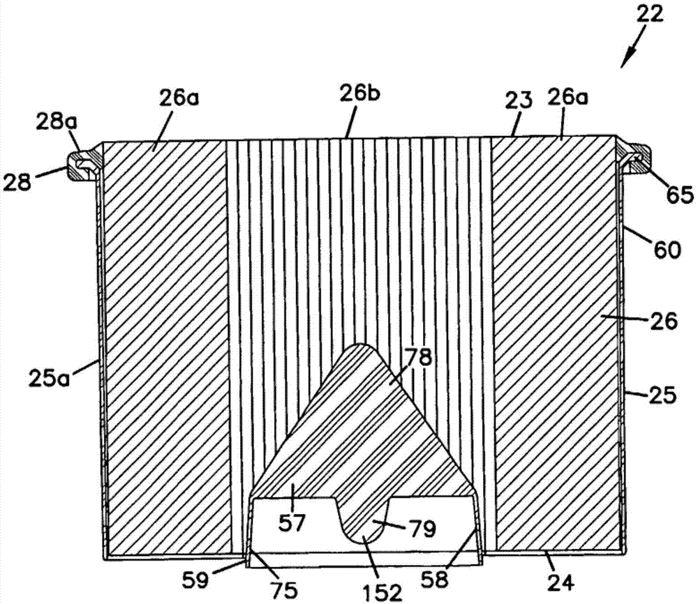
图7所示出的具体的、优选的过滤器滤芯22包括以下部件:预型件(壳)25a;介质包26;中央件或中心57,接纳室58,格栅59;和密封件或密封垫圈件28(栅格59在图2中看的更清楚)。优选的密封件28一般完全环绕介质包26,因此将介质包26的相对流动面23,24,相对围绕介质包26的流动彼此分离。对于所示出的具体结构来说,通过安装在预型件25a上,使密封部件28完全环绕介质包26。对于所示出的具体的、优选的结构来说,密封件28是这样安装的,使轴向密封表面28a离开入口面23的距离不超过15mm,优选不超过8mm,尽管其他方案也是可行的。The specific,
应当指出的是,在附图中,介质包26的主体或直通流动结构是以剖面形式示意性示出的。就是说,没有示出槽纹的细节。至于槽纹细节,为了方便起见,仅在图5的例子中示出。正如前面所指出的,可以使用多种槽纹形状。z-过滤器元件的末端,以及对这些末端的密封的例子,在U.S.Des.396,098;U.S.6,190,432;U.S.Des.D450,827;U.S.6,235,195;U.S.D437,402和U.S.D450,828的附图中有披露,以上所有六份参考文献在此都被结合入本文。It should be noted that in the drawings, the main body or through-flow structure of the
具体参见图6和图7所示出的截面,部位26a示出在哪里以剖面形式将介质包26剖开,以提供图7的视图。部位26b表示这样的部位,其中,图6所示的剖面线7-7位于卷绕介质包26的层间,在26b处示出的表面是波纹状表面。类似于图7的剖面导致,图6所示的剖面线在相对的弯曲端通过卷绕层,不过通过中心部位的层间。Referring specifically to the cross-sections shown in FIGS. 6 and 7 ,
正如下面更详细讨论的,一般放置中心57以分隔卷绕介质层,其中,每层包括固定在所述非槽纹片材上的槽纹片材。As discussed in more detail below, centers 57 are typically placed to separate layers of wound media, where each layer includes a fluted sheet secured to the non-fluted sheet.
参见图6-7A,所示出的优选实施方案示出了预型件(壳)25a、中心57、接纳室58和格栅59是彼此一体。在本文中,"一体的"表示不破坏所定义的装置,所确定的部分不能够彼此分离。总之,这些确定部分包括优选的预型件60。预型件60在组装滤芯22之前制备。滤芯22通常通过将介质包26和预型件60插入模具,并且原位模制密封件28进行组装。下面将对此作更详细的说明。Referring to Figures 6-7A, the preferred embodiment shown shows that the preform (shell) 25a,
仍然参见图6-7A,所述预型件60优选包括模制的塑料材料,如聚丙烯。可用材料的例子是25%玻璃填充,10%云母填充的聚丙烯;如Thermofil聚丙烯或Adell聚丙烯。Still referring to FIGS. 6-7A , the
参见图9-9C,预型件60包括相对端61,62,和延伸其间的侧壁63。靠近末端61,侧壁63具有向外的漏斗状过渡部分64,见图9B,带外壳密封支撑65,包括其上的径向向外的密封支撑部分或唇缘65a。唇缘65a具有通过其中的密封流动孔66,见图9A,用于下面进一步说明的用途。一般,外壳密封支撑65通常被表征为径向方向的,因为它是从预型件60的纵轴67径向向外的,见图9B。Referring to Figures 9-9C, preform 60 includes opposed ends 61, 62, and
正如下面结合图10,10A的说明所指出的,漏斗状过渡部分64开有空间,在组装期间密封剂可以流入。优选在外边缘64a,见图9C,过渡部分64向外展开足够远,以形成间隙,便于在组装期间密封剂流入。As noted below in conjunction with the description of FIGS. 10, 10A, the funnel-shaped
在部位67和68之间的延伸部分,为了方便,侧壁63可以具有略微向下的(或向内的)锥形。In the extension between
在优选结构中,侧壁63沿其长度是不可渗透的,不过其他方案是可行的。同样优选的是,侧壁63与密封件28组合,会至少在介质包26的整个轴向长度延伸,不过其他方案是可行的。In a preferred construction,
在末端62,提供格栅件59延伸通过开口70。格栅件69可以具有多种形状。提供的具体形状(图9A)包括平行的横梁72,中心横梁73,和对角横梁74。一般,格栅件69被安置以支撑介质包26的出口面24,见图7。格栅件59阻止介质受压。At the end 62 a grating
中心横梁73限定其内中心的、伸长的、中空的接纳室75,形成接纳室58,见图7。接纳室75优选具有外纵横比(图9A的外部长度L与图9A的外部宽度W)至少为3:1,优选至少为5:1,最优选在6:1-10:1的范围内。一般并且优选的是,图9A的外部宽度W不超过介质包剖面较长尺寸的大约65%,优选不超过大约50%。
参见图9B和9C,接纳室75优选包括中心内芯76的一部分,包括接纳室75和其上的非中空中心叶片78。另外,优选在接纳室75中提供间隔物79(图9B),以将接纳室75分隔成两侧75a和75b。每侧优选在深度上延伸,从边缘80向内到末端81至少10mm,优选不超过35mm。每侧的通常深度为大约15mm-28mm。每侧的优选形状如图9B所示。Referring to Figures 9B and 9C, the receiving
参见图6和7,接纳室75的外表面包括伸入卷绕介质包26的中心。通常,卷绕介质包26被制作成卷,然后插在接纳室75上。就是说,在通常组装中,介质包26不是以中心76在位进行卷绕的。而是介质包26首先以卷绕形式构成,然后被插入预型件60的内部60a,通过末端61,并继续被向内推,以将叶片57(78)推至介质包26的层间,引导中心75就位。叶片78的近似三角形的形状和较薄的厚度,见图9B,有利于这种组装。Referring to FIGS. 6 and 7 , the outer surface of the receiving
更具体地讲,从接纳室75的内端75c(图9B和9C)延伸,沿壳体25a轴向向内,提供了中心叶或叶片结构78。叶片78优选包括非中空的、三角形形状的叶片78a,在部位75c和78b之间优选不超过3.0mm厚;并且,在顶端78a不超过2mm厚。通常,叶片78在靠近部位75c处大约2mm厚,并且,在顶端78b大约1.0-1.5mm厚(例如1.3mm),其间呈锥形。较薄的、非中空的叶片78有利于将介质包26推入壳体25a,使部分环绕接纳室75。叶片78的形状优选为三角形,圆形顶端78a与接纳室75相对。More specifically, extending from the
叶片结构78优选向内伸入介质包,离开出口端24的距离至少为所述介质包轴向长度的30%,通常为该长度的至少40%。优选叶片78的长度不超过所述介质包轴向长度的75%,通常不超过该长度的60%,因此,叶片78在离介质包26的相对端面23一定间隔处终止。The
图17示出过滤器滤芯22,具有另一种实施方案的预型件360。图17中的具体结构示出模具结构397中的过滤器元件22,会在下面进一步说明。过滤器滤芯22以剖视图的形式示出,并且可以看到另一种中央片或叶片结构378。叶片378有利于将介质包26推入壳体325a。叶片378的形状优选为三角形,具有圆形顶端或顶点378b。FIG. 17 shows a
图17所示叶片378与图9b所示叶片78的差别在于,顶点378b是偏离中心轴67的。就是说,顶点378b的位置偏向轴67的一侧。叶片378具有直角三角形的形状,而不是图9所示出的等边或等腰三角形形状。叶片378通常具有与叶片78相同的穿入介质26的厚度和深度。叶片378的顶点378b偏离中央纵轴67,以方便将叶片378在介质包26的层间推进。当顶点378b偏离中心纵轴67时,叶片378首先进入更接近卷绕介质包26的匝环的介质26的层间。在卷绕介质包的所述匝环部分,介质26的各层不像,例如所述介质包的正中心那样紧密压紧在一起,并由此在介质的各层之间形成了较大的间隙,有利于将叶片378更方便地插入卷绕介质的各层之间。The
现参见图7,所示出的密封结构28固定在预型件60的唇缘或凸缘65(即,外壳密封支撑)上。这也在图8的分解示意图中示出。Referring now to FIG. 7 , the
参见图8,密封件28直接模制到唇缘或支撑65上。另外,密封件28的整体部分90直接模制到介质包26的标记91处,在该部位将密封件28、预型件25a和介质包26密封在一起。密封件91优选直接密封在表面片材46上,并优选完全环绕介质包26。密封件91还优选始于介质包26靠近一个流动面的部分,在这里是流动面23。优选密封件28包括没有部分延伸过流动面。Referring to FIG. 8 , the
参见图8,相对外壳2,密封件28是轴向收紧密封件。具体地讲,它在外壳的部分7和9之间收紧,特别是在外壳延伸部分9a和7a之间。通常,密封件28被设计成安装时在厚度上压缩。优选密封件28的材料包括泡沫密封剂材料,如泡沫聚亚氨酯,这种材料易压缩形成牢固的密封件。可用的聚亚氨酯密封材料包括在美国专利6,350,291和申请日为2002年3月28日的美国申请10/112,097中所披露的,两份文献在此都被结合入本文,不过其他方案是可行的。Referring to FIG. 8 , relative to the
正如所指出的,密封件28具体为轴向收紧密封件(或轴向外壳密封件)。它可以具有较扁平的相对表面28a,28b,或具有隆起或凹槽的相对表面。可以使用其他密封件,包括径向密封件。As indicated, the
一般,表面28a,28b包括外壳接合密封区,因为在密封期间正是这些部位与外壳接合。Typically, the
结合图10,10A,和17以及以下说明,可以理解制备这种类型密封结构的可用方法。在图10中,所示出的介质包26插入预型件60的内部60a。可以理解,介质包26是这样放置的,中心76伸入介质包26,位于介质的各层之间。Possible methods of making this type of sealing structure can be understood with reference to Figures 10, 10A, and 17 and the following description. In FIG. 10 ,
所示出的包括壳体60和介质包26的组件95放置在模具结构97中。模具结构97包括模具底部98和模具盖子99,限定其间的模腔100。模腔100被设计以形成密封件28。密封件28是通过将可固化的树脂分配到模腔100中形成的,优选在组件95放入模具底部98之后并在放置盖子99就位之前。在工作时,会使用发泡的氨基甲酸乙酯(在固化期间优选会增加至少20%的体积,通常至少40%,一般50-100%)。Assembly 95 including
在树脂固化之前,将模具盖子99放置就位。模具盖子提供了部分密封件28的形状。在模制期间,树脂会上升以填充模腔100。这种上升一般涉及流过外壳密封支撑65中的孔66,见图9A。流过所述孔的结果是,在固化之后,密封件28会机械固定在所述密封件支撑65上,因为一部分树脂被固化,并且留在通过孔66的延伸部分。Before the resin cures, the mold cover 99 is placed in place. The mold cover provides part of the
将部分固化的密封件28直接密封在介质包26a上,还可以在部位100进行,因为在该部位,树脂会直接接触所述介质包。通过模腔100的斜面部位102接合介质包26,一般会阻止流过端面23。如果有必要在该部位阻止溢出,可以通过模具使介质包26在该部位收紧;或在该部位将触变边放置在介质包26和模具底部98之间。Sealing the partially cured
参见图10A,在标记103,预型件60的漏斗表面64(图9B)形成了一表面,斜向上朝向介质包26。该斜面有助于将树脂引向所述介质包,并且还能阻止在模制过程中空气滞留在该部位。Referring to FIG. 10A , at 103 , the funnel surface 64 ( FIG. 9B ) of the
图17示出制备本文所述优选类型的密封结构的另一种实施方案。在图17中,所示出的介质包26被插入预型件360的内部360a。所示出的包括壳体360和介质包26的组件395放置在模具结构397中。模具结构397包括模具底部398和模具盖子399,其间形成了模腔400。在该实施方案中,所示出的模腔400充满树脂401。模腔400被设计以形成密封件28。密封件28通过将可固化的树脂分配到模具模腔400中而形成,优选在组件395放入底部398之后,并在放置盖子399就位之前。在工作时,可以使用发泡的氨基甲酸乙酯。在固化期间,发泡的氨基甲酸乙酯优选能增加至少20%的体积,通常至少40%,一般50%-100%。Figure 17 illustrates another embodiment for making a sealing structure of the preferred type described herein. In FIG. 17 , the
在树脂固化之前,将模具盖子399放置在底部398上就位。模具盖子399提供了部分密封件28的形状。在模制期间,树脂会上升以填充模腔400。这种上升通常涉及流过外壳密封支撑65中的孔66(图9a)。流过这些孔的结果是,在固化之后,密封件28会机械固定在所述密封支撑65上,因为一部分树脂被固化,并且留下延伸通过孔66。Before the resin cures, a
因此,根据本发明结构的密封件28(图8)优选同时具有:外壳密封部分,如28a,28b所示出的相对表面,在使用时与外壳密封;和部分28c,与外壳密封部分28a成一体,它提供了:对介质26直接的密封;围绕介质包26的密封;以及介质包26和预型件60,360(或25a)的密封。这些密封部分(28a,28b,28c)优选彼此成一体,并且通过一次树脂注入同时模制而成。在本文中,"成一体的"表示优选地,部位28a,28b,28c均是相同树脂固化或池或量部分,其间不分离。这是优选的,以方便组装,而不需多个密封步骤。Accordingly, a seal 28 (FIG. 8) constructed in accordance with the present invention preferably has both: a housing sealing portion, shown as 28a, 28b as opposed surfaces, in use to seal against the housing; and a portion 28c, formed with the
参见图8,密封件28的优选形状包括部分28d,从表面28a向上(朝向末端23);部分28e朝向相反,以填充漏斗表面64和介质包26之间的部位。部位28a和28b位于唇缘65的相对侧,过渡部分28f优选置于其间延伸。Referring to FIG. 8 , the preferred shape of
角A,介质包26和漏斗表面64之间的锐角,优选在30°-60°的范围延伸,包括端点,更优选在35°-55°间,包括端点。Angle A, the acute angle between
这种类型的模制作业使用的某些原理与申请日为2003年12月22日的美国临时申请60/532,783中的描述相关,该申请的全部内容在此被结合入本文。在该申请中使用的某些技术可以被应用于图8所示的密封结构。应当指出,图8所示密封件的具体位置和形状,以及所使用的预型件的位置和性质完全不同。另外,关于外壳优选是如何接合的,所示出的具体示例的密封件是不同的类型。Some of the principles used by this type of molding operation are related to those described in
尽管所述介质包可以制成多种尺寸和形状,可用在所示出具体结构上的通常的介质包具有轴向长度至少为140mm,较长的剖面长度轴线至少为190mm,较短的剖面轴线或长度至少为110mm。While the media packs described can be made in a variety of sizes and shapes, typical media packs that can be used on the particular construction shown have an axial length of at least 140mm, a longer section length axis of at least 190mm, and a shorter section axis of at least 190mm. Or a length of at least 110mm.
参见图8,一般介质包26和密封件28的密封材料之间的界面,沿所述介质包延伸距离至少4mm,通常5-15mm。该延伸有助于在介质包26和密封件28间提供良好的固定接合。另外,密封件28,对于其上安装有组件1的设备的振动能够起到某些减震作用,这种振动会不理想地传递给介质包26,可能损坏在该部位的介质包26。就是说,材料28的理想减震作用在使用时有利于过滤器滤芯22的完整性。Referring to Figure 8, typically the interface between the
C.可用的安全过滤器C. Available Security Filters
现参见图11-14,示出了可用的安全过滤器20的一个实施方案。在优选系统中,安全过滤器20在空气过滤器1位于主过滤器滤芯22下游,以便万一主过滤器滤芯22损坏时,阻止可能通过主过滤器滤芯22的碎片进入下游部件。另外,安全过滤器20有助于在维修空气过滤器1时保护发动机,防止碎片落入净化空气部位32,见图4。Referring now to Figures 11-14, one embodiment of a
安全过滤器20具有外周170,它优选与主过滤器滤芯22的外周的总体形状匹配。在所示出的实施方案中,安全过滤器20是长圆形的,但可以是其他形状的,如圆形。所示出的具体长圆形形状是跑道形状,具有一对相对侧边172,173,由一对圆形或弯曲的,相对末端174,175连接。The
在所示出的实施方案中,安全过滤器20包括刚性结构框架178。构成框架178一部分的是裙边或裙带180。裙带180环绕过滤介质184的内部。可以使用多种类型的介质184。在所示出的结构中,介质184是折叠的,有折纹185,见图11,平行于直边172,173延伸。例如,可用的折纹密度至少为二个折纹/英寸,通常3-8个折纹/英寸。从图11可以看出具有两个折纹部位186,187。通过框架178的隔板188一般将安全过滤器20分成两部分,将第一折纹部位186从第二折纹部位187分开。隔板188沿安全过滤器20在弯曲末端174和弯曲末端175之间纵向延伸。In the illustrated embodiment,
在所述优选实施方案中,安全过滤器20包括手柄190,其尺寸适合容纳至少部分人手。"其尺寸适合容纳至少部分人手",是指手柄190具有这样的结构,在它和安全元件20的其余部分之间,允许手的至少一部分(一个手指或几个手指)适合放在所述手柄结构和安全过滤器20的其余部分之间,以允许操作安全过滤器20。In the preferred embodiment,
在所示出的实施方案中,安全过滤器20包括从框架178伸出的手柄190。在优选实施方案中,手柄190是隔板188的整体延伸。可以使用多种手柄结构190。在所示出的结构中,手柄190具有至少一个突出部分192,从框架部件189伸出。突出部分192可采用多种结构,包括圆形把手、环、延伸部分等。在所示出的结构中,突出部分192以臂状物194的形式,限定空腔196,见图12。在优选实施方案中,空腔196完全穿过臂状物194。In the illustrated embodiment, the
在特别优选的实施方案中,手柄190包括第二突出部分198。第二突出部分198也可以采用多种形状或结构。在所示出的结构中,突出部分198具有与突出部分192相同的形状,以臂状物202的形式,其间具有空腔204(图12)。In a particularly preferred embodiment, the
在优选实施方案中,空腔196,204的尺寸大到足以容纳人手带手套的手指,以协助相对空气过滤器1操作安全元件。例如,空腔196,204限定至少2cm2,通常4-100cm2的截面积。突出部分192,198由隔板189的过渡平台206彼此分隔开,参见图12。In a preferred embodiment, the
在优选用途中,由过渡平台206和每个突出部分192,198的内侧207,208形成的空间205能够容纳中心57的定心结构79的顶点152(图7),参见图4。在所述优选用途中,突出部分192,198起导向装置212,214(图12)的作用,以帮助将主过滤器滤芯22可操作地定向就位在空气过滤器1中。导向装置212,214的大小有助于将过滤器滤芯22居中放置在空气过滤器1中。In a preferred application, the
仍然参见图11-14,优选的安全过滤器20包括密封部件218,以帮助在安全过滤器20和外壳2的空气过滤器部分9之间形成密封220(图4)。在所示出的结构中,密封件218环绕裙带180的整个周边固定在所述裙带180上。所示出的密封件218在裙带180和外壳2的空气过滤器部分9的内表面120之间,并紧靠裙带形成径向密封221(图4)。Still referring to FIGS. 11-14 , the
可用的介质184可以包括多种不同类型的常见过滤介质。这包括纤维素、合成物和各种混合物。一种可用的常见介质是合成/玻璃纤维混合物,重量为70±4.0磅/3,000英尺2(114±6.5g/m2);厚度为0.032±0.003英寸(0.81±0.08mm);Frazier渗透性为165±20英尺/min.(50.3±6.1m/min.);孔径大小为100±8微米;干抗拉强度为19.8±6.6磅/英寸(9.0±3kg/英寸);爆裂强度为20±5psi(138±34kPa)。
D.可用的预滤器结构D. Available Prefilter Configurations
在图2–4中,示出了优选的预滤器部分8。尽管在主过滤器元件22的上游可以使用多种不同的常见预滤器,优选使用所示出的具体的预滤器8。In Figures 2-4, a preferred
如上文所述,预滤器8包括多个离心式分离器管13,见图2A。每个管13包括外部环绕的大致筒状壁228,在相对端229,230间呈锥形。末端229的直径小于末端230的直径。末端229置于末端230的上游。旋涡发生器232位于壁228内,见图3,包括叶片或弯曲叶片234。壁228在下游端230还包括出口236,见图2A。As mentioned above, the
每个管13被接纳在上游挡板238内,见图2A。挡板238包括多个孔240,其大小适合接纳管13的上游端229。每个管的上游端229具有短小突出部242(图3),被接纳在槽244中,见图2A,是孔240的一部分。该短小突出部/孔形成指引结构246(图3),确保每个管13上的每个出口236指向灰尘排出管4。Each
所示出的优选预滤器8还包括多个提取管250,见图4,被接纳在管228内。在优选实施方案中,每个提取管250作为盖子7的整体部分模制。因此,在优选实施方案中,盖子7包括整体模制的单件部件:侧壁252,管14,下游挡板254,和每个提取管250。The
为组装预滤器8,将每个管228插入挡板238中相应的孔240。指引结构246用于使每个管228的短小突出部对准至相应的槽244,以确保出口236指向排出器管4。其内安装有每个管228的上游挡板238随后朝向预滤器8的其余部分。管228的每个末端230朝向相应的提取管250,并且挡板238,例如通过搭扣配合,固定在侧壁252上。To assemble the
预滤器8按以下方式工作:含有颗粒物的气流流过每个管13的上游端229。气流由旋涡发生器232引起旋转。气流的旋转性质导致离心力作用在气流的颗粒物上。在气流中重于气体的颗粒物朝向壁228移动。The
所述颗粒从出口236排出,而剩余气流流过提取管250。从提取管250,气流向下游流动,并进入主过滤器元件22的上游流动面23。从出口236排出的颗粒物在重力作用下向下落下通过排出管4,并通过排出阀15排出。The particles exit
E.方法E. method
一般,提供了如上所述具有直通流动结构的过滤器元件的密封方法。优选的方法通常包括将如上所述盖子和主空气过滤器部分的相对凸缘与突出的轴向密封垫圈(在所述元件上)接合,并且径向压缩密封垫圈,如图所示。In general, a method of sealing a filter element having a through-flow configuration as described above is provided. The preferred method generally involves engaging the opposed flanges of the cover and main air filter section as described above with the protruding axial sealing gasket (on said element) and compressing the sealing gasket radially, as shown.
提供了将密封垫圈安装在如上所述具有直通流动结构的过滤器滤芯上的方法。一个示例方法通常包括将预型件和介质包密封在一起,将与形成滤芯的外壳密封相同的密封材料注入。A method of installing a sealing gasket on a filter cartridge having a through-flow configuration as described above is provided. One example method generally involves sealing the preform and media pack together, injecting the same sealing material that forms the housing seal of the cartridge.
为净化气体,首先,应当将过滤器(20,22)安装在空气过滤器1中。将包含预滤器的盖子8,从外壳2的空气过滤器部分9移去。提供了安全过滤器20。通过抓住手柄190,如将手指放入空腔196,204,握住并操作安全过滤器20。安全过滤器20通过空气过滤器部分9的开口端放入,并安装在部分32内。垫圈220在壁9间并紧靠壁9压缩,以在安全过滤器20和空气过滤器部分9之间形成径向密封221。To purify the gas, first, the filters ( 20 , 22 ) should be installed in the
参见图4,随后提供主过滤器滤芯22。主过滤器滤芯22是这样操纵的,使下游端24首先通过空气过滤器部分9的开口端放入。接纳室75与要接纳的导向装置212,214对准。具体地讲,中心57具有接纳凹处164,167,见图4,其内接纳导向装置212,214。中心57的定心结构152与导向装置212,214相互作用,以帮助主要元件22在空气过滤器部分9内对齐和居中。Referring to Figure 4, a
按上述将主过滤器滤芯22居中,并定向以使垫圈28放置在空气过滤器部分9的凸缘371上。然后,使预滤器部分7朝向空气过滤器部分9,以使凸缘370放置在垫圈28上。然后用过中心插销或夹具17在接合处11施加轴向力,并在外壳的预滤器部分7和外壳的空气过滤器部分9之间与垫圈28形成轴向密封。凸缘370包括周向延伸部分370a,图8,以覆盖密封件28的外环部分28f。The
为了净化空气,空气经离心管13进入预滤器7。旋涡发生器232促成气流旋转,导致颗粒物朝向壁228移动。颗粒物随后通过出口236排出,在重力作用下通过灰尘排出器管14排出。然后,初步净化的空气流过提取管250,并随后通过主过滤器元件22的入口面23。介质包26从空气中除去其他颗粒材料。净化的空气随后流过出口面24。然后,净化的空气流过可选的安全过滤器20的介质184,并随后通过出口管3。从那里,净化的空气流向下游设备,如发动机。In order to purify the air, the air enters the
在使用一段时间之后,空气过滤器1需要维修。为了维修空气过滤器1,将预滤器部分7从外壳2的空气过滤器部分9拆除。这通过松开夹具实现。当松开夹具17时,解除了由密封垫圈28形成的轴向密封。然后,暴露出过滤器滤芯22的上游面。抓住过滤器滤芯22,并且从空气过滤器部分9中取出。主过滤器滤芯22可以被丢弃或再利用,视情况而定。如果安全过滤器20也需要维修,就抓住手柄190,将安全元件20从空气过滤器部分9中取出,并且丢弃或再利用。应当理解的是,在很多应用中,主过滤器滤芯22需要更换,而安全过滤器元件20不需要更换。After a period of use, the
如果更换安全过滤器20,就将第二个新的安全过滤器元件20插入外壳2,正如在初始安装中所描述的。然后,如上文所述,提供新的主过滤器滤芯22,并将它安装在空气过滤器部分9中。将预滤器部分8放在空气过滤器部分9上,并由垫圈28形成轴向密封。If the
Claims (11)
Applications Claiming Priority (3)
| Application Number | Priority Date | Filing Date | Title |
|---|---|---|---|
| US55613304P | 2004-03-24 | 2004-03-24 | |
| US60/556,133 | 2004-03-24 | ||
| CN200580005628XA CN1921922B (en) | 2004-03-24 | 2005-03-23 | Filter element, air filter assembly and method |
Related Parent Applications (1)
| Application Number | Title | Priority Date | Filing Date |
|---|---|---|---|
| CN200580005628XA Division CN1921922B (en) | 2004-03-24 | 2005-03-23 | Filter element, air filter assembly and method |
Publications (2)
| Publication Number | Publication Date |
|---|---|
| CN103736326A true CN103736326A (en) | 2014-04-23 |
| CN103736326B CN103736326B (en) | 2016-01-06 |
Family
ID=34963662
Family Applications (3)
| Application Number | Title | Priority Date | Filing Date |
|---|---|---|---|
| CN200580005628XA Expired - Lifetime CN1921922B (en) | 2004-03-24 | 2005-03-23 | Filter element, air filter assembly and method |
| CN201310573313.1A Expired - Lifetime CN103736326B (en) | 2004-03-24 | 2005-03-23 | Filter cell, air cleaner assembly and method |
| CN2010101430140A Expired - Lifetime CN101816872B (en) | 2004-03-24 | 2005-03-23 | Filter element, air filter assembly and method |
Family Applications Before (1)
| Application Number | Title | Priority Date | Filing Date |
|---|---|---|---|
| CN200580005628XA Expired - Lifetime CN1921922B (en) | 2004-03-24 | 2005-03-23 | Filter element, air filter assembly and method |
Family Applications After (1)
| Application Number | Title | Priority Date | Filing Date |
|---|---|---|---|
| CN2010101430140A Expired - Lifetime CN101816872B (en) | 2004-03-24 | 2005-03-23 | Filter element, air filter assembly and method |
Country Status (9)
| Country | Link |
|---|---|
| US (6) | US7674308B2 (en) |
| EP (4) | EP1729621B1 (en) |
| JP (3) | JP4664969B2 (en) |
| KR (2) | KR101312868B1 (en) |
| CN (3) | CN1921922B (en) |
| BR (1) | BRPI0507946A (en) |
| MX (2) | MX386667B (en) |
| PL (1) | PL3470130T3 (en) |
| WO (1) | WO2005094655A2 (en) |
Cited By (2)
| Publication number | Priority date | Publication date | Assignee | Title |
|---|---|---|---|---|
| CN109564020A (en) * | 2016-08-08 | 2019-04-02 | 3M创新有限公司 | Air filter condition sensing |
| CN116422094A (en) * | 2019-02-04 | 2023-07-14 | 唐纳森公司 | Filter elements for filtering fluids |
Families Citing this family (161)
| Publication number | Priority date | Publication date | Assignee | Title |
|---|---|---|---|---|
| ZA973639B (en) * | 1996-04-26 | 1998-10-26 | Donaldson Co Inc | Fluted filter media |
| US8449638B2 (en) | 1999-11-05 | 2013-05-28 | Donaldson Company, Inc. | Filter element, air cleaner, and methods |
| US6348084B1 (en) | 1999-11-05 | 2002-02-19 | Donaldson Company, Inc. | Filter element, air cleaner, and methods |
| US6610126B2 (en) | 2001-06-06 | 2003-08-26 | Donaldson Company, Inc. | Filter element having sealing members and methods |
| US6966940B2 (en) | 2002-04-04 | 2005-11-22 | Donaldson Company, Inc. | Air filter cartridge |
| EP1509311B2 (en) | 2002-05-09 | 2008-12-17 | Donaldson Company, Inc. | Air filter having fluted filter media |
| KR20050098922A (en) | 2003-02-11 | 2005-10-12 | 도널드선 컴파니 인코포레이티드 | Air cleaner arrangements; serviceable filter elements;and,method |
| US8226786B2 (en) | 2003-03-18 | 2012-07-24 | Donaldson Company, Inc. | Process and materials for coiling z-filter media, and/or closing flutes of filter media; and, products |
| JP4528305B2 (en) * | 2003-11-12 | 2010-08-18 | ドナルドソン カンパニー,インコーポレイティド | Air filter with slide mount for filter element |
| CN101693158B (en) | 2003-12-22 | 2013-02-20 | 唐纳森公司 | Filter element comprising a seal arrangement and method for making the same |
| JP4664969B2 (en) * | 2004-03-24 | 2011-04-06 | ドナルドソン カンパニー,インコーポレイティド | Filter element, air cleaner, assembly and filtration method |
| US7905936B2 (en) * | 2004-04-30 | 2011-03-15 | Donaldson Company, Inc. | Filter arrangements; housing; assemblies; and, methods |
| MX353255B (en) | 2004-04-30 | 2018-01-05 | Donaldson Co Inc | FILTER ARRANGEMENTS, ACCOMMODATIONS, ASSEMBLIES AND METHODS. |
| JP4638495B2 (en) * | 2004-06-08 | 2011-02-23 | ドナルドソン カンパニー,インコーポレイティド | Z-type filtration medium packing structure and manufacturing method thereof |
| WO2005123222A1 (en) | 2004-06-14 | 2005-12-29 | Donaldson Company, Inc. | Air filter arrangement; assembly; and, methods |
| EP1781397B1 (en) | 2004-06-18 | 2013-06-12 | Donaldson Company, Inc. | Air cleaner arrangements and methods |
| EP1778384B2 (en) | 2004-08-06 | 2017-10-11 | Donaldson Company, Inc. | Air filter assembly |
| US20060091061A1 (en) * | 2004-11-02 | 2006-05-04 | Baldwin Filters, Inc. | Filter assembly with sealing system |
| US20110197556A1 (en) * | 2004-11-02 | 2011-08-18 | Baldwin Filters, Inc. | Filter element |
| US20070186528A1 (en) * | 2006-02-15 | 2007-08-16 | Baldwin Filters, Inc. | Fluted filter apparatus |
| US7318851B2 (en) * | 2004-11-02 | 2008-01-15 | Baldwin Filters, Inc. | Filter element |
| US7931725B2 (en) | 2004-11-02 | 2011-04-26 | Baldwin Filters, Inc. | Fluted filter apparatus |
| US20060091064A1 (en) * | 2004-11-02 | 2006-05-04 | Baldwin Filters, Inc. | Filter apparatus with separable seal support frame |
| US7909954B2 (en) * | 2004-11-03 | 2011-03-22 | Baldwin Filters, Inc. | Method and apparatus for winding a filter media pack |
| US7569090B2 (en) | 2004-11-12 | 2009-08-04 | Donaldson Company, Inc. | Method of forming filter arrangements; and, apparatus |
| US8292983B2 (en) | 2005-01-13 | 2012-10-23 | Donaldson Company, Inc. | Air filter cartridge and air cleaner assembly |
| US7520913B2 (en) | 2005-02-04 | 2009-04-21 | Donaldson Company, Inc. | Non-cylindrical filter elements, and methods |
| WO2006093960A2 (en) * | 2005-02-28 | 2006-09-08 | Donaldson Company, Inc. | Filter arrangement and methods |
| EP1888197A2 (en) * | 2005-06-06 | 2008-02-20 | Ingersoll-Rand Company | Air intake filter assembly |
| DE202005009989U1 (en) * | 2005-06-25 | 2006-11-02 | Mann + Hummel Gmbh | Filter with a filter housing |
| EP1937961B1 (en) | 2005-10-11 | 2012-07-11 | Donaldson Company, Inc. | Air filter cartridge and air cleaner |
| JP2009515096A (en) | 2005-11-09 | 2009-04-09 | ドナルドソン カンパニー,インコーポレイティド | Seal structure of filter element, filter element assembly and method |
| US20070163945A1 (en) * | 2006-01-19 | 2007-07-19 | Baldwin Filters, Inc. | Method and apparatus for reinforcing a tubular-shaped sealing collar extending from a filter apparatus |
| US7753982B2 (en) | 2006-02-17 | 2010-07-13 | Baldwin Filters, Inc. | Filter with drained jacket, seal indicator/lock means, and seal baffle |
| US7625419B2 (en) * | 2006-05-10 | 2009-12-01 | Donaldson Company, Inc. | Air filter arrangement; assembly; and, methods |
| US10040020B2 (en) * | 2006-12-06 | 2018-08-07 | Baldwin Filters, Inc. | Fluid filter apparatus having filter media wound about a winding frame |
| US9757676B2 (en) * | 2006-12-06 | 2017-09-12 | Baldwin Filters, Inc. | Method and apparatus for winding a filter element |
| EP2134444B1 (en) | 2007-02-26 | 2018-06-20 | Donaldson Company, Inc. | Air filter cartridge |
| WO2008125475A1 (en) * | 2007-04-11 | 2008-10-23 | Mann+Hummel Gmbh | Intake air filter |
| KR100887022B1 (en) * | 2007-05-21 | 2009-03-04 | 동 규 김 | Ceiling type air purifier |
| US8066791B2 (en) * | 2007-07-20 | 2011-11-29 | Donaldson Company, Inc. | Air cleaner arrangements with internal and external support for cartridge; components; and, methods |
| EP2190554B1 (en) | 2007-09-07 | 2013-01-09 | Donaldson Company, Inc. | Air filter assembly |
| US9545593B2 (en) * | 2007-11-01 | 2017-01-17 | Baldwin Filters, Inc. | Winding core pressure relief for fluted filter |
| JP2011502782A (en) | 2007-11-15 | 2011-01-27 | ドナルドソン カンパニー,インコーポレイティド | Air filter composition, assembly and method |
| CN102015061B (en) * | 2008-02-25 | 2013-10-30 | 唐纳森公司 | Filter element and method for pulse cleaning |
| US9492773B2 (en) | 2008-02-26 | 2016-11-15 | Mann+Hummel Gmbh | Filter device, especially an air filter |
| EP2829309A1 (en) | 2008-02-26 | 2015-01-28 | Mann + Hummel Gmbh | Multiple bellows filter with increased efficiency |
| BRPI0908027B1 (en) * | 2008-02-26 | 2020-10-20 | Mann + Hummel Gmbh | filter device, especially air filter for an internal combustion engine |
| EP2265354B1 (en) * | 2008-04-04 | 2018-01-10 | Donaldson Company, Inc. | Filter element, dust collector, and method |
| US8048187B2 (en) * | 2008-06-30 | 2011-11-01 | Baldwin Filters, Inc. | Filter frame attachment and fluted filter having same |
| US7959703B2 (en) * | 2008-06-30 | 2011-06-14 | Baldwin Filters, Inc. | Fluted filter with integrated frame |
| CN104524873B (en) | 2008-07-22 | 2017-07-21 | 唐纳森公司 | Air cleaner assembly and its part |
| US8317890B2 (en) * | 2008-08-29 | 2012-11-27 | Donaldson Company, Inc. | Filter assembly; components therefor; and, methods |
| US8506668B2 (en) * | 2009-03-30 | 2013-08-13 | Baldwin Filters, Inc. | Fluted filter with axial seal |
| WO2010114906A1 (en) | 2009-03-31 | 2010-10-07 | Donaldson Company, Inc. | Air cleaner, components thereof, and methods |
| US8192623B2 (en) | 2009-04-01 | 2012-06-05 | Wix Filtration Corp Llc | Filter structure |
| US8061530B2 (en) | 2009-04-09 | 2011-11-22 | Cummins Filtration Ip, Inc. | Filtration sealing system |
| WO2011041129A1 (en) | 2009-10-02 | 2011-04-07 | Donaldson Company, Inc. | Filter cartridge with centerboard, dust collectors, and methods |
| DE102010045669A1 (en) * | 2009-10-12 | 2011-04-21 | Mann+Hummel Gmbh | filter means |
| CA2777529C (en) | 2009-10-14 | 2018-02-13 | Donaldson Company, Inc. | Filter cartridge with seal member and methods |
| DE102009056511A1 (en) * | 2009-12-02 | 2011-06-09 | Mann+Hummel Gmbh | Filter element and method of making a filter element |
| DE102010009249A1 (en) * | 2010-02-25 | 2011-08-25 | MAHLE International GmbH, 70376 | filtering device |
| WO2011115979A2 (en) | 2010-03-17 | 2011-09-22 | Baldwin Filters, Inc. | Fluid filter |
| WO2011115973A2 (en) * | 2010-03-17 | 2011-09-22 | Baldwin Filters, Inc. | Fluid filter |
| US7935161B1 (en) * | 2010-03-23 | 2011-05-03 | Bulkmatic Transport Company | Filter cartridge with mounting apparatus and method of filter replacement for a cyclonic separation system |
| CN102233215A (en) * | 2010-04-21 | 2011-11-09 | 唐纳森(无锡)过滤器有限公司 | Gasket for air filter component, air filter component and method |
| DE102010032169B4 (en) | 2010-07-23 | 2016-11-17 | Mann + Hummel Gmbh | Cyclone separator for separating particles from a gas stream |
| US8568502B2 (en) * | 2010-08-30 | 2013-10-29 | Ford Global Technologies, Llc | Spring clamp for an air filter housing |
| DE102011121352A1 (en) * | 2011-01-31 | 2012-08-02 | Mann+Hummel Gmbh | filtering device |
| US9504949B2 (en) | 2011-06-30 | 2016-11-29 | Donaldson Company, Inc. | Air/oil separator assemblies; components; and methods |
| US8683970B2 (en) * | 2011-07-28 | 2014-04-01 | Cnh America Llc | Air intake system for off-road vehicles |
| CN102305158A (en) * | 2011-08-12 | 2012-01-04 | 重庆长安汽车股份有限公司 | Air inlet system of miniature automobile engine |
| US9387425B2 (en) | 2011-10-26 | 2016-07-12 | Donaldson Company, Inc. | Filter assemblies; components and features thereof; and, methods of use and assembly |
| DE102011122632A1 (en) * | 2011-12-23 | 2013-06-27 | Mann + Hummel Gmbh | Centrifugal separator and filter arrangement |
| USD762291S1 (en) * | 2012-02-08 | 2016-07-26 | Mann+Hummel Gmbh | Air filter |
| EP2877267B1 (en) * | 2012-07-25 | 2022-04-13 | Baldwin Filters, Inc. | Filter housing, fluted filter and safety filter |
| DE102013003753A1 (en) * | 2013-03-06 | 2014-09-11 | Mann + Hummel Gmbh | Filter, filter element and filter housing |
| US9228545B2 (en) * | 2013-03-12 | 2016-01-05 | Caterpillar Inc. | Intake air pre-cleaner |
| US9724635B2 (en) * | 2013-03-14 | 2017-08-08 | Bladwin Filters, Inc. | Rectangular stacked fluted filter cartridge |
| US9816468B2 (en) | 2013-04-16 | 2017-11-14 | Advanced Flow Engineering | Air filter retention interface |
| CN108412645B (en) | 2013-05-22 | 2020-10-16 | 唐纳森公司 | Air cleaner and filter element |
| JP6408570B2 (en) * | 2013-06-28 | 2018-10-17 | ドナルドソン カンパニー,インコーポレイティド | Filter cartridge and air cleaner assembly |
| DE102013011609B4 (en) * | 2013-07-12 | 2017-08-17 | Mann + Hummel Gmbh | Air filter element and this containing air filter |
| US9527018B2 (en) * | 2014-04-01 | 2016-12-27 | Caterpillar Inc. | Debris drain filter system and cartridge |
| DE102014212606B4 (en) * | 2014-06-30 | 2020-12-17 | Ford Global Technologies, Llc | Motor vehicle and air filter box |
| US9500164B2 (en) | 2014-08-29 | 2016-11-22 | Caterpillar, Inc. | Air filter element and filter housing |
| EP3194048B1 (en) | 2014-09-15 | 2020-07-08 | Donaldson Company, Inc. | Filter cartridge and air cleaner assembly |
| DE102015013138A1 (en) * | 2014-10-13 | 2016-04-14 | Mann+Hummel Gmbh | Filter element, in particular for gas filtration |
| US9689334B2 (en) * | 2014-11-14 | 2017-06-27 | Cnh Industrial America Llc | Air intake system for an off-road vehicle |
| US9795907B2 (en) * | 2014-12-01 | 2017-10-24 | DRM Diversafab Corp. | Adapter assembly for securing a precleaner to an air filtration system |
| US10532310B2 (en) | 2014-12-27 | 2020-01-14 | Donaldson Company, Inc. | Filter cartridges; air cleaner assemblies; housings; features; components; and, methods |
| DE102015203138A1 (en) * | 2015-02-20 | 2016-08-25 | Mahle International Gmbh | Air filter element and air filter |
| USD792959S1 (en) | 2015-02-27 | 2017-07-25 | 3M Innovative Properties Company | Filter element having a pattern |
| EP3265209B1 (en) | 2015-03-02 | 2021-02-24 | Donaldson Company, Inc. | Air filter cartridge and air cleaner assembly |
| US20160305375A1 (en) * | 2015-04-15 | 2016-10-20 | Caterpillar Inc. | Filter assembly |
| WO2017066169A1 (en) * | 2015-10-12 | 2017-04-20 | Cummins Filtration Ip, Inc. | Tangential air cleaner with coiled filter cartridge |
| BR122021006809B1 (en) | 2015-10-31 | 2023-04-04 | Saint-Gobain Performance Plastics Corporation | FILTER CAPSULE |
| USD798907S1 (en) | 2015-11-20 | 2017-10-03 | Baldwin Filters, Inc. | Filter element |
| USD786935S1 (en) | 2015-11-20 | 2017-05-16 | Baldwin Filters, Inc. | Filter element |
| AU2016259419B2 (en) | 2015-11-30 | 2020-12-10 | Parker-Hannifin Corporation | Engine Panel Filter and Housing System |
| WO2017099984A1 (en) | 2015-12-11 | 2017-06-15 | Cummins Filtration Ip, Inc. | Filter with variable cross-section axial seal |
| CN118203909A (en) | 2015-12-18 | 2024-06-18 | 唐纳森公司 | Filter cartridge and air cleaner assembly |
| DE102016001134A1 (en) * | 2016-02-03 | 2017-08-03 | Mann + Hummel Gmbh | Filter housing and filter |
| US11167234B2 (en) | 2016-03-18 | 2021-11-09 | Cummins Filtration Ip, Inc. | Interlocked stable filter assembly |
| US10456727B2 (en) * | 2016-03-24 | 2019-10-29 | K&N Engineering, Inc. | Reusable air filter system and method |
| DE102016004316A1 (en) * | 2016-04-12 | 2017-01-26 | Mann + Hummel Gmbh | Filter element and filter assembly |
| US10682597B2 (en) | 2016-04-14 | 2020-06-16 | Baldwin Filters, Inc. | Filter system |
| EP3831460A1 (en) * | 2016-04-15 | 2021-06-09 | Techtronic Floor Care Technology Limited | Handheld vacuum cleaner |
| MX2018013103A (en) | 2016-05-02 | 2019-03-28 | Cummins Filtration Ip Inc | Filter with interlocking housing interface. |
| KR101786345B1 (en) * | 2016-05-18 | 2017-10-18 | 현대자동차주식회사 | Air Cleaner of Air Filter using High Density Filter Paper and Vehicle thereby |
| CN109715265B (en) * | 2016-07-06 | 2021-11-19 | 唐纳森公司 | Air filter assembly |
| DE102016011158A1 (en) * | 2016-09-16 | 2018-03-22 | Mann + Hummel Gmbh | Filter element and filter system |
| EP3311902B1 (en) * | 2016-10-24 | 2020-06-24 | Donaldson Company, Inc. | Air filter element and method for producing same |
| US10400715B2 (en) * | 2016-11-23 | 2019-09-03 | Caterpillar Inc. | Air filter with fluted media and stand-alone preform shell |
| WO2018102712A2 (en) | 2016-12-01 | 2018-06-07 | Donaldson Company, Inc. | Filter elements, air cleaner assemblies, and methods of use and assembly |
| US10357731B2 (en) | 2016-12-20 | 2019-07-23 | Baldwin Filters, Inc. | Filter with preformed end caps having notch feature |
| US11298640B2 (en) | 2017-01-25 | 2022-04-12 | Cummins Filtration Ip, Inc. | Expandable threaded adaptor for threadless shell |
| MX2018001429A (en) * | 2017-02-01 | 2018-11-09 | Tvs Motor Co Ltd | Air filter used for internal combustion engine. |
| CN110382075A (en) | 2017-02-21 | 2019-10-25 | 康明斯滤清系统知识产权公司 | Wavy interlocking cover-end plate interface geometry |
| US10746141B2 (en) | 2017-03-14 | 2020-08-18 | Kohler Co. | Engine air cleaner |
| DE112018000692T5 (en) | 2017-03-16 | 2019-10-17 | Cummins Filtration Ip, Inc. | FILTRATION SEALING SYSTEM |
| PL3664915T3 (en) * | 2017-08-09 | 2023-05-29 | Donaldson Company, Inc. | Air filter cartridge and air cleaner assembly |
| USD885545S1 (en) | 2017-08-09 | 2020-05-26 | Donaldson Company, Inc. | Filter cartridge |
| USD885546S1 (en) | 2017-08-09 | 2020-05-26 | Donaldson Company, Inc. | Filter cartridge |
| US11198082B2 (en) | 2017-08-31 | 2021-12-14 | Donaldson Company, Inc. | Filter cartridges; air cleaner assemblies; housings; features; components; and methods |
| WO2019104330A1 (en) | 2017-11-27 | 2019-05-31 | Donaldson Company, Inc. | Air cleaner assemblies and methods of use |
| CN107998780B (en) * | 2017-11-27 | 2024-04-02 | 姜相宇 | Air purifying method and air purifier |
| CN107795415A (en) * | 2017-11-29 | 2018-03-13 | 蚌埠金威滤清器有限公司 | Efficient through type air cleaner |
| CN108126459A (en) * | 2017-12-29 | 2018-06-08 | 浙江纳风净化技术有限公司 | A kind of outdoor filtered host |
| TWI655026B (en) | 2018-01-25 | 2019-04-01 | 淳靖股份有限公司 | Axial flow filter with side cover |
| CN110075645B (en) * | 2018-01-25 | 2021-09-03 | 淳靖股份有限公司 | Axial flow filter with side cover |
| US10888810B2 (en) * | 2018-02-08 | 2021-01-12 | Mann+Hummel Gmbh | Inline filter system having a pre-separator module |
| US20190277227A1 (en) * | 2018-03-07 | 2019-09-12 | Kros-Wise, Inc. | Air filtration device |
| USD905842S1 (en) | 2018-06-15 | 2020-12-22 | Donaldson Company, Inc. | Filter cartridge |
| WO2020021418A1 (en) | 2018-07-23 | 2020-01-30 | Cummins Filtration Sarl | Radial seal for spin-on filter |
| WO2020112482A1 (en) * | 2018-11-29 | 2020-06-04 | Cummins Filtration Ip, Inc. | Improved layered filter frame |
| EP3666362B1 (en) * | 2018-12-12 | 2022-06-01 | Filtra Group Oy | Device and method for fluid purification |
| USD980382S1 (en) * | 2019-01-28 | 2023-03-07 | Tianjin Premium E-Commerce Co., Ltd. | Filtering device |
| USD1002792S1 (en) | 2019-02-05 | 2023-10-24 | Donaldson Company, Inc. | Filter cartridge |
| BR112021016941A2 (en) | 2019-03-08 | 2021-11-03 | Parker Hannifin Corp | Air filter element and filter element |
| USD941473S1 (en) * | 2019-03-19 | 2022-01-18 | Soclean, Inc. | Filter cartridge |
| US11118545B2 (en) | 2019-03-26 | 2021-09-14 | Caterpillar Inc. | Precleaner system |
| US11465081B2 (en) * | 2019-06-28 | 2022-10-11 | Haier Us Appliance Solutions, Inc. | Water filtering and recycling system for ice making appliance |
| CN114746642B (en) | 2019-11-05 | 2024-11-01 | 帕克-汉尼芬公司 | Gyrotron assembly for engine air purifier and configuration method of gyrotron assembly |
| EP3827891B1 (en) * | 2019-11-28 | 2022-02-16 | Carl Freudenberg KG | Filter element with conductive edge band and filter arrangement comprising such a filter element |
| DE102020200945A1 (en) * | 2020-01-27 | 2021-07-29 | Deere & Company | Air filter system for a commercial vehicle |
| EP3881922B1 (en) | 2020-03-19 | 2024-03-13 | Donaldson Company, Inc. | Filter element with seal receiver |
| USD946733S1 (en) * | 2020-07-05 | 2022-03-22 | Champion Laboratories, Inc. | Filter frame |
| US11666844B2 (en) | 2020-09-30 | 2023-06-06 | Caterpillar Inc. | Filtration device having a latch mechanism adapter |
| US11572853B2 (en) | 2020-10-20 | 2023-02-07 | Kros-Wise, Inc. | Multiple intake air filtration device |
| KR102882484B1 (en) | 2020-10-29 | 2025-11-07 | 현대자동차주식회사 | Reinforcement member for a cover of an air cleaner and the air cleaner comprising the same |
| EP4237696A1 (en) * | 2020-10-30 | 2023-09-06 | Donaldson Company, Inc. | Clip and nut assembly |
| US20230398480A1 (en) * | 2020-11-02 | 2023-12-14 | Cummins Filtration Inc. | Filter assemblies with alignment features |
| EP4035757A1 (en) | 2021-01-27 | 2022-08-03 | Donaldson Company, Inc. | Filter element and method of manufacturing a filter element |
| DE102021105231A1 (en) * | 2021-03-04 | 2022-09-08 | Mann+Hummel Gmbh | Filter element, filter element arrangement and filter system with a filter element arrangement |
| USD1064220S1 (en) | 2022-01-07 | 2025-02-25 | Donaldson Company, Inc. | Filter cartridge |
| USD1067404S1 (en) | 2022-01-07 | 2025-03-18 | Donaldson Company, Inc. | Filter cartridge |
| EP4467221A1 (en) * | 2023-05-25 | 2024-11-27 | MANN+HUMMEL GmbH | Radially oriented, modular pre-cleaner system |
| US20240390920A1 (en) * | 2023-05-25 | 2024-11-28 | Mann+Hummel Gmbh | Radially oriented, modular pre-cleaner system |
| USD1062972S1 (en) * | 2024-04-10 | 2025-02-18 | Xiaocheng Chen | Fumigator |
| CN119656723B (en) * | 2024-12-17 | 2025-08-19 | 潍坊众芯环保科技有限公司 | Air filter element |
Family Cites Families (195)
| Publication number | Priority date | Publication date | Assignee | Title |
|---|---|---|---|---|
| US396098A (en) | 1889-01-15 | Combined strawberry-vine cutter and cultivator | ||
| US1238068A (en) | 1916-06-09 | 1917-08-21 | Electro Fume Company | Fume-disseminator. |
| US2064207A (en) | 1934-05-14 | 1936-12-15 | Ind Wire Cloth Products Compan | Air cleaner combination unit |
| GB612415A (en) | 1944-03-29 | 1948-11-12 | Marconi Wireless Telegraph Co | Magnetron electron discharge devices |
| US2599604A (en) | 1949-07-13 | 1952-06-10 | Jordan V Bauer | Filter element |
| US2890796A (en) | 1957-03-12 | 1959-06-16 | Lewis B Blood | Filter screen in fuel distribution |
| US3025963A (en) | 1958-03-13 | 1962-03-20 | Russell H Curtis | Products useful as filtering devices and methods of making them |
| US3216578A (en) | 1960-12-19 | 1965-11-09 | Donaldson Co Inc | Pleated filter |
| GB945065A (en) | 1961-03-21 | 1963-12-18 | Simonacco Ltd | Improvements in and relating to rotary filters |
| US3293833A (en) | 1963-02-28 | 1966-12-27 | Cambridge Filter Corp | Pleated filter |
| US3209917A (en) | 1964-12-21 | 1965-10-05 | Walker Mfg Co | Filter cartridge |
| GB1121896A (en) | 1966-07-21 | 1968-07-31 | Gen Motors Ltd | Air filters |
| GB1284403A (en) | 1968-08-08 | 1972-08-09 | Exsol Services Ltd | Improvements in and relating to filtering apparatus |
| US3849241A (en) | 1968-12-23 | 1974-11-19 | Exxon Research Engineering Co | Non-woven mats by melt blowing |
| US3841953A (en) | 1970-12-31 | 1974-10-15 | Exxon Research Engineering Co | Nonwoven mats of thermoplastic blends by melt blowing |
| US3676242A (en) | 1969-08-13 | 1972-07-11 | Exxon Research Engineering Co | Method of making a nonwoven polymer laminate |
| US3695012A (en) | 1970-04-23 | 1972-10-03 | Donaldson Co Inc | Filter assembly with pleated filter element |
| US3695437A (en) | 1971-01-11 | 1972-10-03 | Hastings Mfg Co | Oil filter with improved anti-drainback valve |
| US3712033A (en) | 1971-06-01 | 1973-01-23 | Donaldson Co Inc | Air cleaner with hinged side walls |
| US3807150A (en) | 1972-02-28 | 1974-04-30 | Hepa Corp | Absolute filter pack structure having a toroidal section |
| US3912631A (en) | 1972-06-09 | 1975-10-14 | William C Turman | Oil filter and adapter |
| US4065341A (en) | 1972-11-21 | 1977-12-27 | Robert Bosch Gmbh | Method of making a liquid filter |
| US3878014A (en) | 1973-04-30 | 1975-04-15 | Beloit Corp | Process for matting melt blow microfibers |
| AU473778B2 (en) | 1973-05-19 | 1976-07-01 | Mitsubishi Denki Kabushki Kaisha | Filter device and method of producing the same |
| US4093435A (en) | 1973-11-23 | 1978-06-06 | Wing Industries Inc. | Total heat energy exchangers |
| US4259330A (en) * | 1976-03-01 | 1981-03-31 | Rohm And Haas Company | Nematocidal phosphoramidates |
| DE2656713A1 (en) | 1976-12-15 | 1978-06-22 | Mende & Co W | CHIPBOARD |
| FR2382258A2 (en) | 1977-03-02 | 1978-09-29 | Gen Electric | High-pressure filter assembly - for radially outward flow through filter screen and perforated basket |
| US4187091A (en) | 1977-05-16 | 1980-02-05 | Donaldson Company, Inc. | Pleated paper filter cartridge |
| US4242115A (en) | 1979-02-05 | 1980-12-30 | Donaldson Company, Inc. | Air cleaner assembly |
| US4255175A (en) | 1979-10-12 | 1981-03-10 | American Air Filter Company, Inc. | Gas separation filter device having a handle |
| CA1115433A (en) * | 1979-10-26 | 1981-12-29 | David C.I. Pollock | Method for protecting a bioreactor pressurized head tank against extreme surges of influent waste water |
| US4322231A (en) | 1980-06-16 | 1982-03-30 | Farr Company | Filter element locking mechanism |
| US4316801A (en) | 1980-07-22 | 1982-02-23 | Pall Corporation | Filter assembly with jacked filter cannister |
| USRE32185E (en) | 1980-10-10 | 1986-06-17 | Donaldson Company, Inc. | Self-cleaning pulsed air cleaner |
| US4331459A (en) | 1980-10-10 | 1982-05-25 | Donaldson Company, Inc. | Self-cleaning pulsed air cleaner |
| EP0152513B1 (en) | 1981-02-23 | 1991-01-09 | Nippondenso Co., Ltd. | Filter element for fluid cleaner systems |
| JPS57140555A (en) * | 1981-02-23 | 1982-08-31 | Nippon Denso Co Ltd | Fluid cleaner |
| US4410430A (en) | 1981-05-11 | 1983-10-18 | California Institute Of Technology | Stacked-disc structure for fluid filter or valve silencer |
| DE3270599D1 (en) | 1981-07-16 | 1986-05-22 | Massey Ferguson Services Nv | Cab with heating and/or ventilating system |
| US4410427A (en) | 1981-11-02 | 1983-10-18 | Donaldson Company, Inc. | Fluid filtering device |
| US4394147A (en) | 1981-11-30 | 1983-07-19 | Allis-Chalmers Corporation | Internally supported filter |
| US4402830A (en) | 1982-01-13 | 1983-09-06 | Pall Corporation | Corrugated filter element with external spiral tape support |
| US4449993A (en) | 1982-07-19 | 1984-05-22 | Equifab, Inc. | Filter module for dust collector system |
| US4575422A (en) | 1983-02-25 | 1986-03-11 | Zimmer Cornelius P | Paper roll filter structure |
| JPS606870U (en) | 1983-06-28 | 1985-01-18 | 株式会社 土屋製作所 | Air cleaner with pre-cleaner |
| GB8329395D0 (en) | 1983-11-03 | 1983-12-07 | Ciba Geigy Ag | Photopolymerisable compositions |
| JPS60112320A (en) | 1983-11-24 | 1985-06-18 | Hitachi Ltd | Tri-state gate protection method |
| JPS6091218U (en) * | 1983-11-30 | 1985-06-22 | 株式会社 土屋製作所 | Air cleaner with honeycomb element interior |
| JPS60112320U (en) | 1983-12-28 | 1985-07-30 | 株式会社 土屋製作所 | Air cleaner with built-in honeycomb element with conical part |
| JPS60155921A (en) | 1984-01-25 | 1985-08-16 | Nippon Soken Inc | Rotary angle detection apparatus |
| JPS60124622U (en) | 1984-01-31 | 1985-08-22 | 株式会社 土屋製作所 | Air cleaner with honeycomb element interior |
| JPS59170669A (en) | 1984-03-09 | 1984-09-26 | 松下冷機株式会社 | Motor compressour controller for refrigerator, etc. |
| JPS60155921U (en) * | 1984-03-28 | 1985-10-17 | 株式会社 土屋製作所 | air cleaner |
| US4617122A (en) | 1984-08-01 | 1986-10-14 | Donaldson Company, Inc. | Crimp seal pleated filter assembly |
| IL74873A (en) | 1985-04-10 | 1990-07-12 | Drori Mordeki | Multiple disc type filter and disc construction useful therein |
| US4673503A (en) | 1985-07-18 | 1987-06-16 | Tokyo Roki Co., Ltd. | Variant length pleated filter element |
| GB8607513D0 (en) | 1986-03-26 | 1986-04-30 | Barrington R B | Filter for dry cleaning solvent |
| US4720292B1 (en) | 1986-07-14 | 1991-09-10 | Cylindrical air filter with lightweight housing and radially directed seal | |
| JPS6333612A (en) | 1986-07-29 | 1988-02-13 | Toshiba Corp | Optical fiber gyroscope |
| US4746340A (en) | 1986-10-28 | 1988-05-24 | Donaldson Company, Inc. | Air cleaner apparatus |
| JPS63122617A (en) | 1986-11-13 | 1988-05-26 | Lion Corp | skin cleanser |
| JP2643153B2 (en) | 1987-07-03 | 1997-08-20 | セイコーエプソン株式会社 | High frequency bias sputtering equipment |
| JPH01171615A (en) | 1987-12-25 | 1989-07-06 | Toyo Roki Seizo Kk | Filter element |
| JPH029858A (en) | 1988-06-28 | 1990-01-12 | Tosoh Corp | Production of phenyl chlorothioformates |
| JPH0214455U (en) * | 1988-07-11 | 1990-01-30 | ||
| JPH0231131A (en) | 1988-07-20 | 1990-02-01 | Rigaku Keisoku Kk | Method of industrial analysis of coal and infrared heating oven |
| JPH02129233A (en) | 1988-11-08 | 1990-05-17 | Kanebo Ltd | Flame-retardant phenol resin prepreg |
| DE4031014C2 (en) | 1989-04-06 | 1993-11-18 | Mann & Hummel Filter | Intake air filter for internal combustion engines |
| US5443891A (en) | 1989-06-13 | 1995-08-22 | Alberta Research Council | Low amplitude wave-board |
| US4963171A (en) | 1989-11-02 | 1990-10-16 | Donaldson Company, Inc. | High efficiency filter and method of fabricating same |
| US4997466A (en) | 1989-12-26 | 1991-03-05 | Ingersoll-Rand Company | Air filter attachment for compressor |
| US5211846A (en) | 1990-07-30 | 1993-05-18 | Pleatco Electronic & Filter Corp. | Replacement filter cartridge assembly |
| US5290621A (en) | 1990-10-03 | 1994-03-01 | Her Majesty The Queen In Right Of Canada As Represented By The Minister Of Forestry | Flat-topped wave-board panel |
| US5238474A (en) | 1990-10-19 | 1993-08-24 | Donaldson Company, Inc. | Filtration arrangement |
| US5128037A (en) * | 1990-12-27 | 1992-07-07 | Millipore Corporation | Spiral wound filtration membrane cartridge |
| US5240479A (en) | 1991-05-17 | 1993-08-31 | Donaldson Company, Inc. | Pleated filter media having a continuous bead of adhesive between layers of filtering material |
| JP3239517B2 (en) | 1992-06-17 | 2001-12-17 | 株式会社デンソー | Manufacturing method of filtration element |
| US5304312A (en) | 1992-07-27 | 1994-04-19 | Eastman Kodak Company | Filter assembly includng filter unit having deformable sealing end caps |
| US5376271A (en) | 1993-03-29 | 1994-12-27 | Morgan, Jr.; H. William | Liquid filtration unit |
| US5350515A (en) | 1993-03-29 | 1994-09-27 | W. L. Gore & Associates, Inc. | Internally potted end cap for a pleated filter medium |
| DE9305767U1 (en) | 1993-04-16 | 1993-06-17 | Filterwerk Mann & Hummel Gmbh, 7140 Ludwigsburg | Air filters for the interior of motor vehicles |
| US5679122A (en) | 1993-08-14 | 1997-10-21 | Minnesota Mining & Manufacturing Company | Filter for the filtration of a fluid flow |
| US5415676A (en) | 1993-08-16 | 1995-05-16 | Donaldson Company, Inc. | Mist collector cartridge |
| US5487767A (en) | 1993-09-30 | 1996-01-30 | Dana Corporation | Radially sealed air filters |
| US5415677A (en) | 1993-12-28 | 1995-05-16 | Dana Corporation | Air filters including filters configured for both radial and axial sealing |
| US5547480A (en) | 1994-01-21 | 1996-08-20 | Donaldson Company, Inc. | Cylindrical air filter with radially directed seal |
| US5484466A (en) | 1994-02-14 | 1996-01-16 | Baldwin Filters, Inc. | Air filter element with radial seal sealing gasket |
| JP3299622B2 (en) | 1994-03-11 | 2002-07-08 | 豊田紡織株式会社 | Air cleaner device |
| US5472463A (en) | 1994-06-14 | 1995-12-05 | Cummins Engine Company, Inc. | Pressure side integrated air filter and filtering networks for engines |
| DE19524677A1 (en) | 1994-07-07 | 1996-01-11 | Nippon Denso Co | Air-conditioning filter insert of simple construction having strengthened end-section |
| JPH0828376A (en) | 1994-07-11 | 1996-01-30 | Nippondenso Co Ltd | Air cleaner for internal combustion engine |
| US5674302A (en) | 1994-07-12 | 1997-10-07 | Nippondenso Co., Ltd. | Automobile filter element |
| DE4430333C2 (en) | 1994-08-29 | 2000-02-17 | Mann & Hummel Filter | filter |
| FR2726483B1 (en) | 1994-11-09 | 1997-01-24 | Siebec Sa | FILTER CARTRIDGE WITH MOBILE CROWN HOLDING |
| US5613992A (en) | 1994-11-23 | 1997-03-25 | Donaldson Company, Inc. | Reverse flow air filter arrangement and method |
| US5938804A (en) | 1994-11-23 | 1999-08-17 | Donaldson Company, Inc. | Reverse flow air filter arrangement and method |
| CA2163167A1 (en) | 1994-11-30 | 1996-05-31 | Dennis B. Keller | Filter with molded end cap and media spacer |
| DE4443676C2 (en) | 1994-12-08 | 1998-08-13 | Hengst Walter Gmbh & Co Kg | Filters with a filter housing and a replaceable filter element arranged therein |
| WO1996021501A1 (en) | 1995-01-12 | 1996-07-18 | Donaldson Company, Inc. | Filter element |
| WO1996022823A1 (en) | 1995-01-27 | 1996-08-01 | Mine Safety Appliances Company | Respirator filter system |
| DE19539463B4 (en) * | 1995-02-08 | 2005-07-14 | Mann + Hummel Gmbh | Housing, in particular for an air filter for the intake air of an internal combustion engine |
| US5536290A (en) | 1995-02-17 | 1996-07-16 | W. L. Gore & Associates, Inc. | Pleated cartridge filter attachment for top loading filter assemblies |
| JP3499320B2 (en) * | 1995-03-09 | 2004-02-23 | 豊田紡織株式会社 | Air filter |
| US5667545A (en) | 1995-07-03 | 1997-09-16 | Toyoda Boshoku Corporation | Filter element for air cleaner and method of manufacturing the same |
| US5846495A (en) | 1995-07-12 | 1998-12-08 | Engelhard Corporation | Structure for converter body |
| US5531892A (en) | 1995-09-15 | 1996-07-02 | Minnesota Mining And Manufacturing Company | Zigzag filter media and frame having triangular pleat stabilizing elements |
| US5624559A (en) | 1995-10-27 | 1997-04-29 | H-Tech, Inc. | Bag filter and retainer therefor |
| US5685985A (en) | 1995-12-20 | 1997-11-11 | Baldwin Filters, Inc. | Environmentally friendly filter cartridge |
| DE19548197C2 (en) | 1995-12-22 | 1999-05-20 | Freudenberg Carl Fa | Pleated filter insert |
| DE19654188C5 (en) | 1995-12-26 | 2010-09-23 | Toyoda Boshoku Corp., Kariya-shi | Filter element and method for its production |
| JPH09234321A (en) | 1996-02-29 | 1997-09-09 | Tenetsukusu:Kk | Filter member attaching apparatus |
| US5795361A (en) | 1996-03-12 | 1998-08-18 | Dana Corporation | Filter configuration |
| ZA973639B (en) | 1996-04-26 | 1998-10-26 | Donaldson Co Inc | Fluted filter media |
| US5792247A (en) | 1996-04-26 | 1998-08-11 | Donaldson Company, Inc. | Integrated resonator and filter apparatus |
| US5895574A (en) | 1996-04-26 | 1999-04-20 | Donaldson Company, Inc. | Rolled liquid filter using fluted media |
| USD425189S (en) | 1996-04-26 | 2000-05-16 | Donaldson Company, Inc. | Combined filter element and frame therefor |
| USD417268S (en) | 1996-04-26 | 1999-11-30 | Donaldson Company, Inc. | Oval filter |
| US5820646A (en) | 1996-04-26 | 1998-10-13 | Donaldson Company, Inc. | Inline filter apparatus |
| US5902364A (en) * | 1996-04-26 | 1999-05-11 | Donaldson Company, Inc. | Conical filter |
| USD398046S (en) | 1996-04-26 | 1998-09-08 | Donaldson Company, Inc. | Combined filter element and frame therefor |
| USD399944S (en) | 1996-04-26 | 1998-10-20 | Donaldson Company, Inc. | Conical filter |
| DE19632618C2 (en) | 1996-08-13 | 1998-06-18 | Freudenberg Carl Fa | Filter insert |
| DE19638790A1 (en) | 1996-09-21 | 1998-03-26 | Mann & Hummel Filter | Air filter |
| US5902361A (en) | 1996-10-24 | 1999-05-11 | Minnesota Mining And Manufacturing Co. | Filter device for filtering a fluid |
| US5730766A (en) | 1996-11-05 | 1998-03-24 | Bha Group, Inc. | Non-round unitary filter cartridge |
| US5895524A (en) | 1996-12-20 | 1999-04-20 | The Boeing Company | Making thin film metal particulates |
| US5782944A (en) | 1997-03-18 | 1998-07-21 | Purolator Products Air Filtration Company | Moisture resistant air filter |
| JP3662092B2 (en) | 1997-03-21 | 2005-06-22 | 東洋▲ろ▼機製造株式会社 | Filter element and manufacturing method thereof |
| US5897787A (en) | 1997-08-21 | 1999-04-27 | Dresser Industries, Inc. | Strainer and method for separating solid particles from a liquid |
| US6017379A (en) | 1998-04-29 | 2000-01-25 | Mac Equipment, Inc. | Cartridge filter |
| DE19821676A1 (en) | 1998-05-14 | 1999-11-18 | Freudenberg Carl Fa | Filter cassette with a filter element inserted in a rigid frame |
| JP3298052B2 (en) | 1998-08-21 | 2002-07-02 | 豊田紡織株式会社 | Air filter |
| US6391076B1 (en) | 1999-01-29 | 2002-05-21 | Nelson Industries, Inc. | Full flow filter |
| USD461003S1 (en) | 1999-02-26 | 2002-07-30 | Donaldson Company, Inc. | Filter element having sealing system |
| US6235195B1 (en) | 1999-02-26 | 2001-05-22 | Donaldson Company, Inc. | Filter element incorporating a handle member |
| USD447549S1 (en) | 1999-02-26 | 2001-09-04 | Donaldson Company, Inc. | Filter frame holding flexible, irregular media |
| US6221122B1 (en) | 1999-02-26 | 2001-04-24 | Donaldson Company, Inc. | Filter element and methods |
| US6179890B1 (en) | 1999-02-26 | 2001-01-30 | Donaldson Company, Inc. | Air cleaner having sealing arrangement between media arrangement and housing |
| EP1159052B2 (en) | 1999-02-26 | 2011-08-03 | Donaldson Company, Inc. | Sealing system for filter |
| USD450827S1 (en) | 1999-02-26 | 2001-11-20 | Donaldson Company, Inc. | Filter element having sealing system |
| US6190432B1 (en) | 1999-02-26 | 2001-02-20 | Donaldson Company, Inc. | Filter arrangement; sealing system; and methods |
| US6187073B1 (en) | 1999-03-17 | 2001-02-13 | Donaldson Company, Inc. | Air cleaner; aerosol separator; and method |
| US6676721B1 (en) | 2000-06-02 | 2004-01-13 | Donaldson Company, Inc. | Multistage air cleaner including pulse cleaning system |
| DE19935297A1 (en) | 1999-07-27 | 2001-02-01 | Mahle Filtersysteme Gmbh | Filter body of a fluid filter, especially an air filter |
| US6348084B1 (en) | 1999-11-05 | 2002-02-19 | Donaldson Company, Inc. | Filter element, air cleaner, and methods |
| USD444219S1 (en) | 1999-11-05 | 2001-06-26 | Donaldson Company, Inc. | Centerpiece for filter element |
| USD437402S1 (en) | 1999-11-05 | 2001-02-06 | Donaldson Company, Inc. | Filter element with centerpiece |
| US6348085B1 (en) | 1999-11-10 | 2002-02-19 | Donaldson Company, Inc. | Filter arrangement and methods |
| USD439963S1 (en) | 1999-12-03 | 2001-04-03 | Donaldson Company, Inc. | Panel filter |
| USD450828S1 (en) | 2000-06-13 | 2001-11-20 | Donaldson Company, Inc. | Fluted filter element having a handle |
| US6368374B1 (en) * | 2000-06-13 | 2002-04-09 | Donaldson Company, Inc. | Filter arrangement and methods |
| US6482247B2 (en) | 2000-06-23 | 2002-11-19 | Nelson Industries, Inc. | Multi-panel fluid filter with equalized contaminant passages |
| US6375700B1 (en) | 2000-06-23 | 2002-04-23 | Nelson Industries, Inc. | Direct flow filter |
| AU7169801A (en) * | 2000-06-30 | 2002-01-14 | Donaldson Co Inc | Air filter assembly for filtering air having particulate matter |
| US6673136B2 (en) | 2000-09-05 | 2004-01-06 | Donaldson Company, Inc. | Air filtration arrangements having fluted media constructions and methods |
| US20020092423A1 (en) | 2000-09-05 | 2002-07-18 | Gillingham Gary R. | Methods for filtering air for a gas turbine system |
| US6432177B1 (en) | 2000-09-12 | 2002-08-13 | Donaldson Company, Inc. | Air filter assembly for low temperature catalytic processes |
| US6416561B1 (en) | 2000-10-20 | 2002-07-09 | Nelson Industries, Inc. | Open flow filter with safety element |
| US6568540B1 (en) | 2000-12-13 | 2003-05-27 | Nelson Industries, Inc. | Low force closure filter with integral seal |
| US6511599B2 (en) | 2000-12-18 | 2003-01-28 | Nelson Industries, Inc. | Multi-element cylindrical filter with equalized flow |
| US6743317B2 (en) | 2000-12-19 | 2004-06-01 | Robert M. Wydeven | Method of sealing, housing and constructing honeycomb filters |
| DE10063789A1 (en) | 2000-12-21 | 2002-06-27 | Mann & Hummel Filter | Filter element for face flow |
| US6533847B2 (en) | 2001-02-13 | 2003-03-18 | Donaldson Company, Inc. | Adsorption apparatus |
| US6447567B1 (en) | 2001-05-14 | 2002-09-10 | Baldwin Filters, Inc. | Air filter element with integral radial seal gasket |
| US6610126B2 (en) * | 2001-06-06 | 2003-08-26 | Donaldson Company, Inc. | Filter element having sealing members and methods |
| US6517598B2 (en) | 2001-06-06 | 2003-02-11 | Donaldson Company, Inc. | Filter element having flange and methods |
| US6852141B2 (en) | 2001-06-06 | 2005-02-08 | Donaldson Company, Inc. | Filter element having center piece and methods |
| US6544918B1 (en) | 2001-07-17 | 2003-04-08 | Equistar Chemicals, Lp | Olefin polymerization catalysts containing chelating dianionic ligands |
| DE10152552A1 (en) | 2001-10-24 | 2003-05-08 | Mann & Hummel Filter | Filter element, in particular for the filtration of liquids |
| JP2003155981A (en) * | 2001-11-21 | 2003-05-30 | Toyota Industries Corp | Operation control method for vacuum pump and operation controller thereof |
| US6966940B2 (en) * | 2002-04-04 | 2005-11-22 | Donaldson Company, Inc. | Air filter cartridge |
| EP1509311B2 (en) * | 2002-05-09 | 2008-12-17 | Donaldson Company, Inc. | Air filter having fluted filter media |
| DE10222800B4 (en) | 2002-05-23 | 2013-06-27 | Mann + Hummel Gmbh | Filter in a filter housing |
| EP1982754A3 (en) | 2002-08-08 | 2008-12-03 | Mann+Hummel Gmbh | Filter system |
| EP3141294B1 (en) | 2002-10-28 | 2022-07-20 | Donaldson Company, Inc. | Air filter cartridge |
| US7300486B1 (en) | 2003-04-02 | 2007-11-27 | Wix Filtration Corp Llc | Filter elements having injection molded thermoplastic seals and methods of making same |
| WO2005037408A1 (en) | 2003-10-14 | 2005-04-28 | Donaldson Company, Inc. | Filter assembly with pleated media v-packs, and methods |
| CN101693158B (en) | 2003-12-22 | 2013-02-20 | 唐纳森公司 | Filter element comprising a seal arrangement and method for making the same |
| JP4664969B2 (en) | 2004-03-24 | 2011-04-06 | ドナルドソン カンパニー,インコーポレイティド | Filter element, air cleaner, assembly and filtration method |
| USD506539S1 (en) * | 2004-03-24 | 2005-06-21 | Donaldson Company, Inc. | Filter cartridge |
| MX353255B (en) | 2004-04-30 | 2018-01-05 | Donaldson Co Inc | FILTER ARRANGEMENTS, ACCOMMODATIONS, ASSEMBLIES AND METHODS. |
| US20060091064A1 (en) | 2004-11-02 | 2006-05-04 | Baldwin Filters, Inc. | Filter apparatus with separable seal support frame |
| US7318851B2 (en) | 2004-11-02 | 2008-01-15 | Baldwin Filters, Inc. | Filter element |
| US20060091061A1 (en) | 2004-11-02 | 2006-05-04 | Baldwin Filters, Inc. | Filter assembly with sealing system |
| US20060091084A1 (en) | 2004-11-02 | 2006-05-04 | Baldwin Filters, Inc. | Fluted filter media with intermediate flow restriction and method of making same |
| US8042694B2 (en) | 2004-11-02 | 2011-10-25 | Baldwin Filters, Inc. | Gathered filter media for an air filter and method of making same |
| CA2728613C (en) | 2004-12-29 | 2015-06-09 | Baldwin Filters, Inc. | Filter canister with locking base plate |
| US7520913B2 (en) | 2005-02-04 | 2009-04-21 | Donaldson Company, Inc. | Non-cylindrical filter elements, and methods |
| US20080011672A1 (en) | 2005-09-01 | 2008-01-17 | Schwartz Scott W | Direct Flow Filter Including Auxiliary Filter |
| JP2009515096A (en) | 2005-11-09 | 2009-04-09 | ドナルドソン カンパニー,インコーポレイティド | Seal structure of filter element, filter element assembly and method |
| US7753982B2 (en) | 2006-02-17 | 2010-07-13 | Baldwin Filters, Inc. | Filter with drained jacket, seal indicator/lock means, and seal baffle |
| US7931723B2 (en) | 2006-03-09 | 2011-04-26 | Donaldson Company, Inc. | Filter assembly with pleated media pockets, and methods |
| DE202008017059U1 (en) | 2008-12-23 | 2010-05-12 | Mann + Hummel Gmbh | Filter device for internal combustion engines |
| CN204065626U (en) | 2014-10-27 | 2014-12-31 | 京东方科技集团股份有限公司 | Array base palte, display panel and display device |
-
2005
- 2005-03-23 JP JP2007505169A patent/JP4664969B2/en not_active Expired - Fee Related
- 2005-03-23 EP EP05729276A patent/EP1729621B1/en not_active Expired - Lifetime
- 2005-03-23 KR KR1020127010079A patent/KR101312868B1/en not_active Expired - Lifetime
- 2005-03-23 CN CN200580005628XA patent/CN1921922B/en not_active Expired - Lifetime
- 2005-03-23 WO PCT/US2005/009813 patent/WO2005094655A2/en not_active Ceased
- 2005-03-23 EP EP13153716.9A patent/EP2644247B1/en not_active Expired - Lifetime
- 2005-03-23 MX MX2016008425A patent/MX386667B/en unknown
- 2005-03-23 US US10/587,766 patent/US7674308B2/en not_active Expired - Lifetime
- 2005-03-23 CN CN201310573313.1A patent/CN103736326B/en not_active Expired - Lifetime
- 2005-03-23 CN CN2010101430140A patent/CN101816872B/en not_active Expired - Lifetime
- 2005-03-23 EP EP13161605.4A patent/EP2679293A1/en not_active Withdrawn
- 2005-03-23 EP EP18182379.0A patent/EP3470130B1/en not_active Expired - Lifetime
- 2005-03-23 MX MX2010003858A patent/MX340081B/en unknown
- 2005-03-23 BR BRPI0507946-2A patent/BRPI0507946A/en active IP Right Grant
- 2005-03-23 KR KR1020067019486A patent/KR101312897B1/en not_active Expired - Lifetime
- 2005-03-23 PL PL18182379T patent/PL3470130T3/en unknown
-
2010
- 2010-01-22 US US12/692,114 patent/US8101003B2/en not_active Expired - Lifetime
- 2010-04-21 JP JP2010097490A patent/JP5555530B2/en not_active Expired - Lifetime
-
2012
- 2012-01-23 US US13/356,205 patent/US8778043B2/en not_active Expired - Lifetime
-
2013
- 2013-07-05 JP JP2013142126A patent/JP5787940B2/en not_active Expired - Lifetime
-
2014
- 2014-07-10 US US14/328,073 patent/US9610530B2/en not_active Expired - Lifetime
-
2017
- 2017-02-22 US US15/439,228 patent/US10335730B2/en not_active Expired - Lifetime
-
2019
- 2019-07-01 US US16/458,358 patent/US11014036B2/en not_active Expired - Lifetime
Cited By (2)
| Publication number | Priority date | Publication date | Assignee | Title |
|---|---|---|---|---|
| CN109564020A (en) * | 2016-08-08 | 2019-04-02 | 3M创新有限公司 | Air filter condition sensing |
| CN116422094A (en) * | 2019-02-04 | 2023-07-14 | 唐纳森公司 | Filter elements for filtering fluids |
Also Published As
Similar Documents
| Publication | Publication Date | Title |
|---|---|---|
| CN103736326B (en) | Filter cell, air cleaner assembly and method | |
| JP7564267B2 (en) | FILTER CARTRIDGE, AIR CLEANER ASSEMBLY, HOUSING, FEATURES, COMPONENTS AND METHODS | |
| JP7337993B2 (en) | air purifier assembly | |
| CN101909719B (en) | Air filter construction, assembly and method | |
| KR102803632B1 (en) | Filter elements, systems, and methods | |
| CA2730549C (en) | Filter elements; air cleaner; assembly; and, methods | |
| JP4989769B2 (en) | Air cleaner assembly | |
| CN109689180B (en) | Air Cleaner Assemblies and Elements | |
| JP2010194540A5 (en) | ||
| MXPA06010723A (en) | Filter elements;air cleaner;assembly;and, methods | |
| BRPI0507946B1 (en) | Air filter cartridge, and method for making such a cartridge |
Legal Events
| Date | Code | Title | Description |
|---|---|---|---|
| C06 | Publication | ||
| PB01 | Publication | ||
| C10 | Entry into substantive examination | ||
| SE01 | Entry into force of request for substantive examination | ||
| C14 | Grant of patent or utility model | ||
| GR01 | Patent grant | ||
| CX01 | Expiry of patent term | ||
| CX01 | Expiry of patent term |
Granted publication date: 20160106 |