CN103679860A - Home anti-theft system and working method thereof - Google Patents
Home anti-theft system and working method thereof Download PDFInfo
- Publication number
- CN103679860A CN103679860A CN201210355773.2A CN201210355773A CN103679860A CN 103679860 A CN103679860 A CN 103679860A CN 201210355773 A CN201210355773 A CN 201210355773A CN 103679860 A CN103679860 A CN 103679860A
- Authority
- CN
- China
- Prior art keywords
- key
- gateway controller
- circuit
- server
- lockset
- Prior art date
- Legal status (The legal status is an assumption and is not a legal conclusion. Google has not performed a legal analysis and makes no representation as to the accuracy of the status listed.)
- Granted
Links
Images


Landscapes
- Lock And Its Accessories (AREA)
Abstract
本发明提供一种家居防盗系统及其工作方法,提供数码防盗锁钥匙开锁权限可配置的解决方案。家居防盗系统由钥匙和锁具、网关控制器、服务器及客户端组成,锁具读取钥匙的身份识别码信息,与存储的钥匙身份识别码数据进行判断,根据判断的结果来进行不同操作:正确,钥匙正常开锁;错误锁具则启动闭锁,并向网关控制器发送开锁权限请求指令,网关控制器再向服务器申请。本系统利用ID数码防盗锁状态检测、ID码判断、通信技术,将ID数码防盗锁状态及钥匙开锁权限实现管理与配置,及通过客户端实现钥匙开锁权限或时限分配,从而实现锁具远程控制与管理,方便用户对钥匙权限控制,实现数码锁智能化管理。
The invention provides a home anti-theft system and its working method, and provides a solution in which the unlocking authority of a digital anti-theft lock key can be configured. The home anti-theft system is composed of keys and locks, gateway controller, server and client. The lock reads the ID information of the key, judges it with the stored key ID data, and performs different operations according to the results of the judgment: correct, The key unlocks normally; the wrong lock starts to lock, and sends an unlock permission request command to the gateway controller, and the gateway controller then applies to the server. This system uses ID digital anti-theft lock state detection, ID code judgment, and communication technology to manage and configure the ID digital anti-theft lock state and key unlocking authority, and realize the key unlocking authority or time limit allocation through the client, so as to realize remote control of locks. Management, which is convenient for users to control the key authority, and realizes the intelligent management of digital locks.
Description
技术领域 technical field
本发明涉及家居安防领域技术领域,特别是涉及一种家居防盗系统及其工作方法。本发明采用数码防盗技术,通过网关控制器对防盗锁报警、状态检测及钥匙权限管理的系统,涉及到防盗锁状态检测、报警、钥匙权限申请及远程钥匙授权及其工作方法,并涉及到安防、互联网以及电子商务领域。The invention relates to the technical field of home security, in particular to a home anti-theft system and a working method thereof. The present invention adopts digital anti-theft technology, and uses a gateway controller to alarm the anti-theft lock, state detection and key authority management system, and involves anti-theft lock state detection, alarm, key authority application, remote key authorization and its working method, as well as security protection , Internet and e-commerce.
背景技术 Background technique
目前,家居防盗系统中,尤其是防盗门系统中,对防盗锁实现远程控制及钥匙权限管理尚处于空白,虽然市面有各种各样的数码防盗锁,而且集成了复杂功能,但尚不能对钥匙权限管理及通过互联网控制。在人们的日常生活中,常常因为钥匙的管理控制不好,造成钥匙的丢失或被盗用,使得用户家居财产及人身安全得不到保障,这种常用的使用钥匙的方式也体现不出高品质的时尚生活。特别对高档和智能化管理小区来说,对钟点工手中钥匙的管理就显得不足,无法控制其开门时间段、权限及开门次数,往往需要用户家庭成员全程跟踪,从而浪费了用户的宝贵时间,另外也不放心把钥匙单独交给服务人员或物业来保管。因此不能进行远程的授权的家居防盗系统,不可避免影响到用户正常的时间安排。而对于指纹、密码或刷卡的门锁来说,涉及密码保密问题,更需要用户家里成员才能使用。给时尚人士的生活带来诸多不便,无法把门锁安全性、互联网应用与生活结合到一起。At present, in the home anti-theft system, especially in the anti-theft door system, the remote control of the anti-theft lock and the management of key authority are still blank. Key authority management and control via the Internet. In people's daily life, the key is often lost or stolen due to poor management and control of the key, so that the user's home property and personal safety cannot be guaranteed. This common way of using the key does not reflect high quality. fashion life. Especially for high-end and intelligent management communities, the management of the keys in the hands of hourly workers is insufficient, and it is impossible to control the time period, authority and number of door openings. It often requires the user's family members to track the whole process, thus wasting the precious time of the user. Don't worry about leaving the keys alone to the service personnel or the property for safekeeping. Therefore, the home anti-theft system that cannot carry out remote authorization will inevitably affect the normal time arrangement of the user. For the door locks with fingerprints, passwords or swiping cards, it involves password confidentiality issues, and requires members of the user's family to use them. It brings a lot of inconvenience to the lives of fashion people, and it is impossible to combine the safety of door locks, Internet applications and life.
发明内容 Contents of the invention
本发明所要解决的技术问题在于提供一种家居防盗系统及其工作方法,解决现有防盗锁钥匙权限管理存在不足,能够远程进行授权等防盗管理,提高家居的安全性。The technical problem to be solved by the present invention is to provide a home anti-theft system and its working method, which solves the deficiency in the authority management of existing anti-theft lock keys, enables remote anti-theft management such as authorization, and improves home security.
本发明是通过以下技术方案来实现的:The present invention is achieved through the following technical solutions:
家居防盗系统,包括有:钥匙和锁具,所述钥匙包括有用于开启锁具的钥匙体;其中,所述家居防盗系统还包括有:网关控制器、服务器及客户端;The home anti-theft system includes: a key and a lock, and the key includes a key body for opening the lock; wherein, the home anti-theft system also includes: a gateway controller, a server and a client;
所述钥匙,包括有包含身份识别码信息的身份识别装置;The key includes an identification device including identification code information;
所述锁具,包括有:锁体、锁芯及电路部件;所述锁体安装在家居设备上,包括有闭锁机构和开锁机构;所述电路部件读取操作中的钥匙的身份识别码信息,与存储的身份识别码数据相比较,正确,钥匙可继续开锁,并通过网关控制器向服务器发送状态;错误,锁具闭锁,并向网关控制器发送开锁权限请求指令,网关控制器再向服务器进行申请,服务器处理后回发给网关控制器,网关控制器把数据再发给锁具实现开锁;The lock includes: a lock body, a lock cylinder and circuit components; the lock body is installed on household equipment and includes a locking mechanism and an unlocking mechanism; the circuit component reads the identification code information of the key in operation, Compared with the stored identification code data, if it is correct, the key can continue to unlock, and the status will be sent to the server through the gateway controller; if it is wrong, the lock will be locked, and the unlock permission request command will be sent to the gateway controller, and then the gateway controller will send the request instruction to the server. After the application is processed, the server sends it back to the gateway controller, and the gateway controller sends the data to the lock to realize unlocking;
所述网关控制器,用于与锁具和服务器进行数据交互;The gateway controller is used for data interaction with the lockset and the server;
所述服务器,作为用户信息管理、锁具信息管理、钥匙与权限管理的服务平台;所述服务器包括有接入及应用处理功能模块和数据库,与智能设备,如网关控制器和客户端分别交互通信;The server is used as a service platform for user information management, lock information management, and key and authority management; the server includes access and application processing function modules and a database, and interacts with smart devices, such as gateway controllers and clients, respectively ;
所述客户端,作为用户操作的终端,用于与服务器进行数据交互,通过服务器查询及配置,进行信息管理及权限管理。在其中一个实施例中,所述锁具的电路部件包括有:The client, as a terminal operated by a user, is used to perform data interaction with the server, and perform information management and authority management through server query and configuration. In one of the embodiments, the circuit components of the lock include:
CPU:用于数据检测处理及控制;CPU: used for data detection, processing and control;
检测电路:用于检测锁具状态及钥匙状态;Detection circuit: used to detect the state of the lock and the state of the key;
存储电路:用于保存信息和数据;Storage circuit: used to save information and data;
身份识别码读取电路:用于读取身份识别码信息;Identification code reading circuit: used to read the identification code information;
以及通信电路:用于与网关控制器进行有线或无线通信;and a communication circuit: for wired or wireless communication with the gateway controller;
所述CPU与检测电路、存储电路、身份识别码读取电路和通信电路分别电气连接;检测电路检测到钥匙状态,身份识别码读取电路读取钥匙的身份识别码信息,发送给CPU;CPU把钥匙的身份识别码信息与存储电路中存储的身份识别码相比较,结果正确,钥匙可进行开锁,结果错误,锁具闭锁,并向网关控制器发送开锁权限请求指令。The CPU is electrically connected to the detection circuit, the storage circuit, the identification code reading circuit and the communication circuit respectively; the detection circuit detects the state of the key, and the identification code reading circuit reads the identification code information of the key and sends it to the CPU; Comparing the identification code information of the key with the identification code stored in the storage circuit, if the result is correct, the key can be unlocked; if the result is wrong, the lock is locked, and an unlock permission request command is sent to the gateway controller.
在其中一个实施例中,所述网关控制器,包括有:CPU单元、通信单元、存储单元以及检测控制单元;CPU单元用于状态检测数据处理和控制,分别与通信单元、存储单元以及检测单元电气连接;所述存储单元,用于保存代码和数据;通信单元用于网关控制器与锁具、服务器、或智能终端设备通信;检测控制单元用于接口状态检测和控制。In one of the embodiments, the gateway controller includes: a CPU unit, a communication unit, a storage unit, and a detection control unit; the CPU unit is used for state detection data processing and control, and communicates with the communication unit, the storage unit, and the detection unit respectively electrical connection; the storage unit is used to store codes and data; the communication unit is used for the gateway controller to communicate with locks, servers, or intelligent terminal equipment; the detection control unit is used for interface state detection and control.
在其中一个实施例中,所述客户端,包括有:客户端管理模块和浏览器,采用电脑或平板电脑或智能手机或手持终端;所述客户端实现登陆和信息交互;所述客户端实现查询、设置和授权,所述客户端实现信息管理和钥匙管理。In one of the embodiments, the client includes: a client management module and a browser, using a computer or a tablet computer or a smart phone or a handheld terminal; the client implements login and information interaction; the client realizes Inquiry, setting and authorization, the client implements information management and key management.
上述家居防盗系统的工作方法,其中:包括钥匙权限管理方法,具体步骤为:The working method of the above-mentioned home anti-theft system, which includes a key authority management method, and the specific steps are:
S1用户通过客户端登录服务器核对钥匙的身份;The S1 user logs in to the server through the client to check the identity of the key;
S2选择需要分配权限的钥匙;S2 selects the key that needs to be assigned authority;
S3选择钥匙权限配置模式,包括:开锁时间段、开锁次数、次数与时间段结合的模式;S3 selects the key permission configuration mode, including: unlocking time period, unlocking times, combination of times and time periods;
S4设置完成后,选择保存设置,钥匙权限管理设置完成。After the S4 setting is completed, select to save the setting, and the key authority management setting is completed.
上述家居防盗系统的工作方法,其中:包括钥匙申请开锁管理方法,具体步骤为:The working method of the above-mentioned home anti-theft system, which includes the key application unlocking management method, the specific steps are:
K1钥匙插入锁具,锁具判断钥匙类型及状态,如为受限状态时,锁具向网关控制器发出开锁申请信息;The K1 key is inserted into the lock, and the lock judges the type and status of the key. If it is in a restricted state, the lock sends an unlock application message to the gateway controller;
K2网关控制器把接收到的开锁申请信息向服务器递交;The K2 gateway controller submits the received unlocking application information to the server;
K3服务器根据配置的权限,把授权结果信息发送给网关控制器;The K3 server sends the authorization result information to the gateway controller according to the configured permissions;
K4网关控制器把服务器发过来的授权结果信息发给锁具;The K4 gateway controller sends the authorization result information sent by the server to the lock;
K5用户进行开锁。The K5 user unlocks the lock.
进一步地,上述钥匙申请开锁管理方法,还包括如下步骤:Further, the above key application unlocking management method also includes the following steps:
K6如锁具提示开锁错误,需要拔出钥匙后,再重新插入钥匙来触发开锁申请过程;依次重复步骤K1、步骤K2、步骤K3、步骤K4、步骤K5;K6 If the lock indicates an error in unlocking, it is necessary to pull out the key and then reinsert the key to trigger the unlocking application process; repeat step K1, step K2, step K3, step K4, and step K5 in sequence;
K7用户开锁后,钥匙申请开锁管理流程结束。After the K7 user unlocks, the key application unlock management process ends.
本发明的有益效果如下:The beneficial effects of the present invention are as follows:
本发明针对现有防盗锁钥匙权限管理存在不足,无法远程进行授权等问题,提供一种通过互联网实现数码防盗锁及钥匙权限管理的家居防盗系统及其工作方法,用户可使用智能手机或PC电脑作为客户端登录服务器来查询钥匙权限、授权情况及钥匙使用记录,配置钥匙使用时限或使用许可次数。应用过程中,权限限制的钥匙在每次使用时需要进行权限申请,由用户通过智能手机或PC电脑登录服务器对钥匙权限进行分配,或预先设置钥匙权限。通过此方法解决钥匙权限管理问题,方便用户管理。The present invention aims at problems such as lack of authority management of existing anti-theft lock keys and the inability to perform remote authorization, etc., and provides a home anti-theft system and its working method for realizing digital anti-theft lock and key authority management through the Internet. Users can use smart phones or PC computers Log in to the server as a client to query key authority, authorization status, and key usage records, and configure the key usage time limit or number of licenses. During the application process, the permission-restricted key needs to apply for permission every time it is used, and the user logs in to the server through a smartphone or PC computer to allocate the key permission, or set the key permission in advance. This method solves the problem of key authority management and facilitates user management.
本发明的家居防盗系统可以运用到防盗门上或者其他家居设备上。The home anti-theft system of the present invention can be applied to anti-theft doors or other home devices.
附图说明 Description of drawings
图1为本发明家居防盗系统的各部件组成结构示意图;Fig. 1 is the composition structure diagram of each component of home antitheft system of the present invention;
图2为本发明家居防盗系统的钥匙结构示意图;Fig. 2 is a schematic diagram of the key structure of the home anti-theft system of the present invention;
图3为本发明家居防盗系统的锁具结构示意图;Fig. 3 is the structural schematic diagram of the lockset of home antitheft system of the present invention;
图4为本发明家居防盗系统的锁具电路原理示意图;Fig. 4 is a schematic diagram of the lock circuit principle of the home anti-theft system of the present invention;
图5为本发明家居防盗系统的网关控制器结构示意图;Fig. 5 is a structural schematic diagram of the gateway controller of the home anti-theft system of the present invention;
图6为本发明家居防盗系统的网关控制器电路原理示意图;6 is a schematic diagram of the gateway controller circuit principle of the home anti-theft system of the present invention;
图7为本发明家居防盗系统的服务器应用原理示意图;Fig. 7 is a schematic diagram of the server application principle of the home anti-theft system of the present invention;
图8为本发明家居防盗系统的客户端应用原理示意图;Fig. 8 is a schematic diagram of the client application principle of the home anti-theft system of the present invention;
图9为本发明家居防盗系统的工作方法的钥匙权限管理方法流程图;Fig. 9 is a flow chart of the key authority management method of the working method of the home anti-theft system of the present invention;
图10为本发明家居防盗系统的工作方法的钥匙申请开锁管理方法流程图。Fig. 10 is a flow chart of the key application unlocking management method of the working method of the home anti-theft system of the present invention.
具体实施方式 Detailed ways
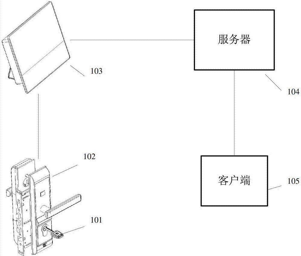
为了解决现有技术的问题,提出了一种家居防盗系统,如图1、2、3,包括有:钥匙101和锁具102,所述钥匙101包括有用于开启锁具的钥匙体;其中,所述家居防盗系统还包括有:网关控制器103、服务器104及客户端105;In order to solve the problems of the prior art, a home anti-theft system is proposed, as shown in Figures 1, 2, and 3, including: a key 101 and a
所述钥匙101,包括有包含身份识别码信息的身份识别装置;The key 101 includes an identification device including identification code information;
所述锁具102,包括有:锁体、锁芯及电路部件;所述锁体安装在家居设备上,包括有闭锁机构和开锁机构;所述电路部件读取操作中的钥匙的身份识别码信息,与存储的身份识别码数据相比较,正确,钥匙可继续开锁,并通过网关控制器向服务器发送状态;错误,锁具闭锁,并向网关控制器发送开锁权限请求指令,网关控制器再向服务器进行申请,服务器处理后回发给网关控制器,网关控制器把数据再发给锁具实现开锁;The
所述网关控制器103,用于与锁具和服务器进行数据交互;The
所述服务器104,作为用户信息管理、锁具信息管理、钥匙与权限管理的服务平台;所述服务器包括有接入及应用处理功能模块和数据库,与智能设备,如网关控制器和客户端分别交互通信;The
所述客户端105,作为用户操作的终端,用于与服务器进行数据交互,通过服务器查询及配置,进行信息管理及权限管理。The
在其中一个实施例中,如图4,所述锁具102的电路部件包括有:In one of the embodiments, as shown in FIG. 4 , the circuit components of the
CPU:用于数据检测处理及控制;CPU: used for data detection, processing and control;
检测电路:用于检测锁具状态及钥匙状态;Detection circuit: used to detect the state of the lock and the state of the key;
存储电路:用于保存信息和数据;Storage circuit: used to save information and data;
身份识别码读取电路:用于读取身份识别码信息;Identification code reading circuit: used to read the identification code information;
以及通信电路:用于与网关控制器进行有线或无线通信;and a communication circuit: for wired or wireless communication with the gateway controller;
所述CPU与检测电路、存储电路、身份识别码读取电路和通信电路分别电气连接;检测电路检测到钥匙状态,身份识别码读取电路读取钥匙的身份识别码信息,发送给CPU;CPU把钥匙的身份识别码信息与存储电路中存储的身份识别码相比较,结果正确,钥匙可进行开锁,结果错误,锁具闭锁,并向网关控制器发送开锁权限请求指令。The CPU is electrically connected to the detection circuit, the storage circuit, the identification code reading circuit and the communication circuit respectively; the detection circuit detects the state of the key, and the identification code reading circuit reads the identification code information of the key and sends it to the CPU; Comparing the identification code information of the key with the identification code stored in the storage circuit, if the result is correct, the key can be unlocked; if the result is wrong, the lock is locked, and an unlock permission request command is sent to the gateway controller.
在其中一个实施例中,如图5、6,所述网关控制器103,包括有:CPU单元、通信单元、存储单元以及检测控制单元;CPU单元用于状态检测数据处理和控制,分别与通信单元、存储单元以及检测单元电气连接;所述存储单元,用于保存代码和数据;通信单元用于网关控制器与锁具、服务器、或智能终端设备通信;检测控制单元用于接口状态检测和控制。In one of the embodiments, as shown in Figures 5 and 6, the
在其中一个实施例中,所述客户端,如图8,包括有:客户端管理模块和浏览器,采用电脑或平板电脑或智能手机或手持终端;所述客户端实现登陆和信息交互;所述客户端实现查询、设置和授权,所述客户端实现信息管理和钥匙管理。In one of the embodiments, the client, as shown in Figure 8, includes: a client management module and a browser, using a computer or a tablet computer or a smart phone or a handheld terminal; the client realizes login and information interaction; The client implements query, setting and authorization, and the client implements information management and key management.
在其中一个实施例中,所述锁具采用数码防盗锁,数码防盗锁包括有:前面板、锁体、锁芯及后面板;前面板包含结构部件、身份识别码读取电路、按键及状态反馈电路;锁体包含结构部件、锁舌、检测电路与闭锁电路,与锁体的闭锁机构电气连接;锁芯包含齿形和执行机构,与面板及锁体连接;后面板包含结构部件、CPU、通信电路及电池电量检测电路,CPU实现状态检测处理及控制,并与网关控制器通信。In one of the embodiments, the lock adopts a digital anti-theft lock, and the digital anti-theft lock includes: a front panel, a lock body, a lock cylinder and a rear panel; the front panel includes structural components, an identification code reading circuit, buttons and status feedback circuit; the lock body contains structural components, deadbolt, detection circuit and locking circuit, which are electrically connected to the locking mechanism of the lock body; the lock core contains teeth and actuators, which are connected to the panel and the lock body; the rear panel contains structural components, CPU, The communication circuit and the battery power detection circuit, the CPU realizes state detection processing and control, and communicates with the gateway controller.
在其中一个实施例中,所述锁具的电路部件,还包括有:状态提示电路、状态检测电路、闭锁电路以及电池电量检测电路;所述状态提示电路、状态检测电路、闭锁电路和电池电量检测电路分别与CPU连接;CPU实现状态检测处理及控制,状态检测电路检测锁具状态、按键状态及钥匙状态,所述的状态提示电路实现各种状态提示,所述闭锁电路实现锁具闭锁;所述电池电量检测电路实现电池电量检测,并通过状态提示电路进行提示。In one of the embodiments, the circuit components of the lockset also include: a state prompt circuit, a state detection circuit, a locking circuit, and a battery power detection circuit; The circuits are respectively connected to the CPU; the CPU realizes state detection processing and control, the state detection circuit detects the state of the lockset, the state of the button and the state of the key, the state prompt circuit realizes various state prompts, and the locking circuit realizes locking of the lockset; the battery The power detection circuit realizes the battery power detection, and prompts through the status prompt circuit.
所述钥匙为一种ID码钥匙,包含外壳、钥匙体和身份识别装置,所述身份识别装置包括有:电极及ID码芯片,通过电极锁具实现读取钥匙ID码信息。The key is an ID code key, which includes a shell, a key body and an identification device. The identification device includes electrodes and an ID code chip, and the ID code information of the key is read through the electrode lock.
所述网关控制器的通信单元包括有:与智能设备的通信单元和与服务器的通信单元;智能设备通信单元实现智能设备、锁具与网关控制器间的通信,与服务器通信单元实现网关控制器与服务器通信,实现数据交互。The communication unit of the gateway controller includes: a communication unit with the smart device and a communication unit with the server; the smart device communication unit realizes the communication between the smart device, the lockset and the gateway controller, and the communication unit with the server realizes the communication between the gateway controller and the server. The server communicates to realize data interaction.
上述家居防盗系统的工作方法,其中:如图9,包括钥匙权限管理方法,具体步骤为:The working method of the above-mentioned home anti-theft system, wherein: as shown in Figure 9, including the key authority management method, the specific steps are:
S1用户通过客户端登录服务器核对钥匙的身份;The S1 user logs in to the server through the client to check the identity of the key;
S2选择需要分配权限的钥匙;S2 selects the key that needs to be assigned authority;
S3选择钥匙权限配置模式,包括:开锁时间段、开锁次数、次数与时间段结合的模式;S3 selects the key permission configuration mode, including: unlocking time period, unlocking times, combination of times and time periods;
S4设置完成后,选择保存设置,钥匙权限管理设置完成。After the S4 setting is completed, select to save the setting, and the key authority management setting is completed.
步骤S1中,钥匙内置唯一ID码,通过预先的注册操作,把不同功能的钥匙注册到锁具中,钥匙唯一ID码保存到锁具的存储单元里,实现钥匙ID码判断。In step S1, the key has a built-in unique ID code. Through the pre-registration operation, the keys with different functions are registered in the lock, and the unique ID code of the key is stored in the storage unit of the lock to realize the judgment of the key ID code.
上述家居防盗系统的工作方法,其中:如图10,包括钥匙申请开锁管理方法,具体步骤为:The working method of the above-mentioned home anti-theft system, wherein: as shown in Figure 10, includes a key application unlocking management method, and the specific steps are:
K1钥匙插入锁具,锁具判断钥匙类型及状态,如为受限状态时,锁具向网关控制器发出开锁申请信息;The K1 key is inserted into the lock, and the lock judges the type and status of the key. If it is in a restricted state, the lock sends an unlock application message to the gateway controller;
K2网关控制器把接收到的开锁申请信息向服务器递交;The K2 gateway controller submits the received unlocking application information to the server;
K3服务器根据配置的权限,把授权结果信息发送给网关控制器;The K3 server sends the authorization result information to the gateway controller according to the configured permissions;
K4网关控制器把服务器发过来的授权结果信息发给锁具;The K4 gateway controller sends the authorization result information sent by the server to the lock;
K5用户进行开锁。The K5 user unlocks the lock.
进一步地,上述钥匙申请开锁管理方法,还包括如下步骤:Further, the above key application unlocking management method also includes the following steps:
K6如锁具提示开锁错误,需要拔出钥匙后,再重新插入钥匙来触发开锁申请过程;依次重复步骤K1、步骤K2、步骤K3、步骤K4、步骤K5;K6 If the lock indicates an error in unlocking, it is necessary to pull out the key and then reinsert the key to trigger the unlocking application process; repeat step K1, step K2, step K3, step K4, and step K5 in sequence;
K7用户开锁后,钥匙申请开锁管理流程结束。After the K7 user unlocks, the key application unlock management process ends.
步骤K1、K2、K3中,在钥匙插入后,触发状态检测电路,检测到用户正在开锁,同时启动钥匙ID码读取,把读取到的钥匙ID码与已经保存在存储电路中的ID码进行比较,如果相同,进行状态提示,可继续进行开锁操作,并把锁具状态发送给网关控制器,由网关控制器递交给服务器,如果比较错误,则向网关控制器发送开锁请求信息,网关控制器把请求信息再向服务器递交,服务器根据配置情况向网关控制器应答,由网关控制器发送给锁具。In steps K1, K2, and K3, after the key is inserted, the state detection circuit is triggered to detect that the user is unlocking the lock, and at the same time start the key ID code reading, and compare the read key ID code with the ID code stored in the storage circuit. For comparison, if they are the same, a status prompt will be given, and the unlocking operation can be continued, and the lock status will be sent to the gateway controller, and the gateway controller will submit it to the server. If the comparison is wrong, the unlock request information will be sent to the gateway controller, and the gateway control The controller submits the request information to the server, and the server responds to the gateway controller according to the configuration, and the gateway controller sends it to the lock.
如服务器中对应钥匙的权限没有配置,则启动闭锁电路,触动启闭锁机构,强行闭锁,同时状态提示电路提示钥匙ID码错误。If the authority of the corresponding key in the server is not configured, the locking circuit will be activated, the opening and closing mechanism will be triggered, and the lock will be forced. At the same time, the status prompt circuit will prompt that the key ID code is wrong.
如果连续超过三次的钥匙ID码错误,则锁具启动状态提示电路发出警报提示,并把报警信息发送给网关控制器,由网关控制器通知用户。If the key ID codes are wrong for more than three consecutive times, the lock starting state prompt circuit will send out an alarm prompt, and the alarm information will be sent to the gateway controller, which will notify the user.
实施例:Example:
本公开的家居防盗系统,如图1、2所示,本发明由钥匙101、锁具102、网关控制器103、服务器104、智能手机105等五部分组成,钥匙101采用ID码钥匙,锁具102采用ID数码防盗锁,服务器104还包括有WEB服务器、应用软件及数据库。The home anti-theft system of the present disclosure, as shown in Figures 1 and 2, the present invention is composed of five parts such as a key 101, a
ID数码防盗锁是机械与电子的完美结合,如图3、4所示,ID数码防盗锁包括有:前面板202、锁体203、锁芯204及后面板201;前面板内置门铃及状态显示灯电路,实现门铃功能及状态显示;锁体安装在门板内,包含主锁舌、副锁舌与门磁舌,锁体内置状态检测电路与闭锁电路,与锁体的闭锁机构电气连接;锁芯实现钥匙齿形匹配及开锁,安装时与前后面板、锁体连接在一起;后面板包含门把手及内置主控单元CPU电路、无线通信电路及电池电量检测电路,通过主控单元CPU电路实现锁开关状态判断及锁具控制,并通过内置的无线通信电路与网关控制器通信。本发明所使用的钥匙101内置唯一ID码,通过预先的注册操作,把不同功能的钥匙注册到数码锁中,钥匙唯一ID码保存到锁具的存储电路里,实现钥匙ID码判断。ID digital anti-theft lock is a perfect combination of machinery and electronics, as shown in Figure 3 and 4, ID digital anti-theft lock includes:
锁具102的电路部件,如图4所示,包括有主控单元CPU、状态检测电路、ID码读取电路、存储电路、无线通信电路、语音提示电路、按键检测电路、闭锁电路、电池电量检测电路和状态显示电路;所述ID码读取电路、存储电路、无线通信电路、语音提示电路、按键检测电路、闭锁电路、电池电量检测电路和状态显示电路分别与主控单元CPU连接;主控单元CPU实现锁具状态检测处理及控制,按键状态检测电路检测主锁舌及门磁舌开关状态,及钥匙插入状态,钥匙ID码读取电路实现钥匙ID码芯片数据读取,按键检测电路实现锁配置及门铃按钮处理,存储电路实现注册钥匙的ID码数据保存,语音提示电路根据不同的操作进行不同的语音提示功能,无线通信电路是锁与网关控制器进行无线通信的电路,闭锁电路实现在非法钥匙开锁时进行闭锁操作,电池电量检测电路实现电池电量检测,并进行电池低电量提示。在ID码钥匙插入锁芯后,触发状态检测电路,锁具检测到用户正在开锁,同时启动钥匙ID码读取,把读取到的钥匙ID码与已经保存的ID码进行比较,如果相同,进行语音提示,可以继续进行钥匙开锁操作,并把开锁状态通过无线通信电路发送给网关控制器,由网关控制器再把状态发到服务器,如比较ID码错误,则通过无线电路向网关控制器进行申请开锁权限,网关控制器通过互联网把钥匙的权限再向服务器申请,服务器应答钥匙的配置权限,由网关控制器转发给锁。The circuit components of the
上述家居防盗系统的工作方法,如没有开锁权限的钥匙进行开锁,则启动闭锁电路,触动启闭锁机构,强行闭锁,并提示钥匙ID码错误,并向网关控制器发送权限请求信息。The working method of the above-mentioned home anti-theft system, if there is no key with unlocking authority to unlock, then start the locking circuit, touch the opening and closing locking mechanism, forcibly lock, and prompt the key ID code error, and send permission request information to the gateway controller.
如果没有开锁权限钥匙连接超过三次开锁,则锁具启动语音电路发出警报声,并通过无线通信电路把报警信息发送给网关控制器,由网关控制器通知用户,可以是短信方式,也可以是语音方式。If there is no unlocking authority key connected more than three times to unlock, the lock will start the voice circuit to send out an alarm sound, and send the alarm information to the gateway controller through the wireless communication circuit, and the gateway controller will notify the user, which can be by SMS or by voice .
锁具通过按键检测电路实现功能配置及门铃操作,实现钥匙注销和注册、应急密码管理;通过前面板的门铃按键实现门铃及应急密码输入功能。锁具在配置及密码操作过程中,并发出种状态的语音提示。The lock implements function configuration and doorbell operation through the key detection circuit, realizes key cancellation and registration, and emergency password management; the doorbell and emergency password input functions are realized through the doorbell button on the front panel. During the configuration and password operation process of the lock, it will issue voice prompts of various states.
所述钥匙为一种ID码钥匙,由外壳、钥匙体和身份识别装置组成,所述身份识别装置包括有:IC电极及IC码芯片,开锁时,把钥匙插入ID数码防盗锁,钥匙上的IC电极与锁具上的电极接触,并触发ID数码防盗锁读取钥匙ID码,数码锁通过钥匙上的IC电极读取钥匙码。The key is an ID code key, which is composed of a shell, a key body and an identification device. The identification device includes: IC electrodes and IC code chips. When unlocking, insert the key into the ID digital anti-theft lock, and the key on the key The IC electrode is in contact with the electrode on the lock, and triggers the ID digital anti-theft lock to read the key ID code, and the digital lock reads the key code through the IC electrode on the key.
网关控制器103是锁与服务器间进行数据交互的桥梁,如图5、6,网关控制器与锁具采用无线通信方式,网关控制器与服务器通信可采用无线通信方式或有线通信方式,实现网关控制器参数配置以及实现与远程服务器通信,并向用户发送报警信息。钥匙开锁申请时,锁具向网关控制器发送开锁权限请求数据,网关控制器把申请信息发送到服务器,服务器再把钥匙权限信息数据发送给网关控制器,网关控制器再发送给锁具。钥匙的权限由用户进行配置,用户通过客户端登录服务器进行授权或权限设定,授权信息通过客户端发给服务器,当网关控制器登录服务器时,服务器再把信息PUSH到网关控制器进行保存,钥匙开锁时,网关控制器把保存的钥匙权限信息发给ID数码防盗锁,实现了ID数码防盗锁钥匙权限管理及开锁操作过程。The
网关控制器实现原理,如图6所示,网关控制器由主控单元CPU、存储单元、语音电路、状态显示电路、检测电路、电池电量检测电路、无线通信电路、以太网通信电路所组成。主控单元CPU实现状态检测、数据处理及控制,存储单元保存网关控制器代码和数据,实现代码运行。语音电路实现报警信息录音、操作语音提示、发出警报声,外接麦克风及喇叭。状态显示电路实现网关运行状态、报警状态、操作状态显示。检测电路用于网关控制器键盘处理,实现网关控制器功能设置、数码锁注册、录音和放音功能,电池电量检测电路用于对电池电量检测,实现电池低电量报警。无线通信电路包含与数码锁、或智能家居设备双向无线通信,以及与服务器的无线通信电路。网关控制器通过无线通信功能实现防盗报警,服务器通信。以太网通信电路用于网关控制器参数配置。ID数码防盗锁在进行钥匙开锁或权限申请时,发送请求信息到网关控制器,由网关控制器处理后,再把信息递交给服务器,服务器根据钥匙权限配置信息进行应答给网关控制器,实现钥匙开锁申请信息上传及控制信息下发,网关控制器同时保存每次的操作记录。ID数码防盗锁在与网关控制器一起使用时,必须先进行数码锁注册,先操作网关控制器进入注册状态,操作ID数码防盗锁进行注册,实现多把锁或其它的智能家居设备的注册功能。录音及警报功能,网关控制器在收到数码锁报警信息后,启动本地发出高分贝警报声,并把报警信息发给用户,同时上送报警信息给服务器。网关控制器可通过以太网接口实现配置,配置服务器信息、用户信息、无线通信参数等。服务器要下发信息到网关控制器是在网关登录到服务器后,由服务器发送到网关控制器,保证信息同步更新。The implementation principle of the gateway controller, as shown in Figure 6, the gateway controller is composed of a main control unit CPU, a storage unit, a voice circuit, a status display circuit, a detection circuit, a battery power detection circuit, a wireless communication circuit, and an Ethernet communication circuit. The main control unit CPU implements state detection, data processing and control, and the storage unit saves the code and data of the gateway controller to realize code operation. The voice circuit realizes alarm information recording, operation voice prompts, and alarm sounds, and is connected to an external microphone and speaker. The status display circuit realizes the display of the gateway running status, alarm status and operation status. The detection circuit is used for gateway controller keyboard processing to realize gateway controller function setting, digital lock registration, recording and playback functions, and the battery power detection circuit is used for battery power detection to realize low battery alarm. The wireless communication circuit includes two-way wireless communication with a digital lock or smart home equipment, and a wireless communication circuit with a server. The gateway controller realizes anti-theft alarm and server communication through the wireless communication function. The Ethernet communication circuit is used for parameter configuration of the gateway controller. When the ID digital anti-theft lock is unlocking the key or applying for permission, it sends the request information to the gateway controller. After the gateway controller processes the information, it then submits the information to the server. The unlocking application information is uploaded and the control information is issued, and the gateway controller saves each operation record at the same time. When the ID digital anti-theft lock is used with the gateway controller, the digital lock must be registered first, and the gateway controller is operated to enter the registration state, and the ID digital anti-theft lock is operated to register, so as to realize the registration function of multiple locks or other smart home devices . Recording and alarm function, after the gateway controller receives the alarm information of the digital lock, it will start the local high-decibel alarm sound, send the alarm information to the user, and send the alarm information to the server at the same time. The gateway controller can realize configuration through the Ethernet interface, configure server information, user information, wireless communication parameters, etc. The server sends information to the gateway controller after the gateway logs in to the server, and the server sends it to the gateway controller to ensure that the information is updated synchronously.
如图7,所述服务器的应用功能模块包括有:钥匙注册管理单元、权限查询管理单元、钥匙注销管理单元等。服务器是用户信息管理、ID数码防盗锁信息管理、钥匙与权限管理的服务平台,实现用户登录、信息查询、钥匙管理、钥匙权限分配等功能,客户端登录服务器后,实现用户信息管理、钥匙权限设置及钥匙管理。服务器端,用户需要注册用户、ID数码防盗锁及钥匙信息,由服务器保存在数据库中。锁具向网关控制器发送开锁申请时,由网关控制器把申请信息发送给服务器,服务器对该信息进行处理,把钥匙权限信息再回发给网关控制器,由网关控制器发送给ID数码防盗锁,完成整个操作过程。As shown in FIG. 7 , the application function modules of the server include: a key registration management unit, an authority query management unit, a key cancellation management unit, and the like. The server is a service platform for user information management, ID digital anti-theft lock information management, key and authority management, and realizes functions such as user login, information query, key management, and key authority distribution. Settings and key management. On the server side, users need to register users, ID digital anti-theft locks and key information, which are stored in the database by the server. When the lock sends an unlocking application to the gateway controller, the gateway controller sends the application information to the server, the server processes the information, and sends the key authority information back to the gateway controller, which then sends it to the ID digital anti-theft lock , to complete the entire operation process.
服务器应用实现框图,如图7所示,服务器负责处理网关控制器和客户端的连接,支持HTML及XML的交互,包含有应用功能模块、APACHE服务器、PHP5处理器、Zend Framework框架、数据库及支持模板与文件所组成,应用功能模块实现不同的操作请求,并通过WEB服务器进行交互,并由PHP5进行XML或HTML解释,再传递到Zend Framework WEB应用程度框架,并与数据库进行信息交互,应答信息再由APACHE web服务器应答给网关控制器或客户端,本发明应用到的服务器框架是基于WEB方式,可以方便服务实现与部署。The server application implementation block diagram, as shown in Figure 7, the server is responsible for processing the connection between the gateway controller and the client, supports HTML and XML interaction, including application function modules, APACHE server, PHP5 processor, Zend Framework framework, database and support templates Composed of files, the application function modules implement different operation requests, and interact through the WEB server, and interpret XML or HTML by PHP5, and then pass it to the Zend Framework WEB application framework, and exchange information with the database, and then respond to the information The APACHE web server responds to the gateway controller or the client, and the server framework applied in the present invention is based on the WEB mode, which can facilitate service realization and deployment.
客户端,是指客户端软件或浏览器,在智能手机或PC电脑上安装客户端软件或通过浏览器登录,可以是智能手机、平板电脑、PC电脑或手持终端。实现用户信息管理、钥匙管理及钥匙权限设置,查询锁具状态或报警信息。用户在配置钥匙权限时,登录到服务器,对钥匙进行授权,并可按开锁的时间段、开锁许可次数、周期性进行配置。服务器记录钥匙的开锁权限,当钥匙进行开锁申请或网关控制连接时,服务器钥匙权限信息发送给网关控制器,网关控制器再把权限信息发送给ID数码防盗锁,实现开锁。The client refers to the client software or browser. Install the client software on a smartphone or PC or log in through a browser. It can be a smartphone, tablet, PC or handheld terminal. Realize user information management, key management and key permission setting, query lock status or alarm information. When configuring the key authority, the user logs in to the server, authorizes the key, and configures it according to the unlocking time period, unlocking permission times, and periodicity. The server records the unlocking authority of the key. When the key applies for unlocking or the gateway controls the connection, the server key authority information is sent to the gateway controller, and the gateway controller then sends the authority information to the ID digital anti-theft lock to realize unlocking.
客户端应用实现框图,如图8所示,客户端基于标准HTML5网页设计,通过HTML或XML与服务器进行交互,以智能手机和平板电脑为主,也支持PC机。客户端界面采用支持HTML5的网页设计,选用JQUERY UI和JQUERYMOBILE的JAVASCRIPT应用框架,支持主流浏览器,可通过智能手机、平板电脑和PC端浏览器进行连接,实现与服务器的HTML或XML交互,通过网页交互实现智能防盗系统的登录、查询、设置等功能。The client application implementation block diagram is shown in Figure 8. The client is based on the standard HTML5 web page design, and interacts with the server through HTML or XML. It mainly uses smartphones and tablets, and also supports PCs. The client interface adopts a web design that supports HTML5, and uses the JAVASCRIPT application framework of JQUERY UI and JQUERYMOBILE to support mainstream browsers. It can be connected through smartphones, tablets and PC browsers to realize HTML or XML interaction with the server. Web page interaction realizes functions such as login, query, and setting of the intelligent anti-theft system.
本发明家居防盗系统的特点为:The characteristics of the home anti-theft system of the present invention are:
1、该防盗系统中的钥匙权限可灵活配置。1. The key permissions in the anti-theft system can be flexibly configured.
2、该防盗系统提供用户远程查询锁具状态、配置开锁时限的手段和方法。2. The anti-theft system provides means and methods for users to remotely query the status of the lock and configure the time limit for unlocking.
3、该防盗系统可以通过智能手机或PC电脑作为客户端查询锁具开闭锁状态,配置钥匙权限。3. The anti-theft system can use a smartphone or PC as a client to query the lock opening and closing status and configure key permissions.
4、该系统与数码锁实现门锁联动,实现防盗报警。4. The system realizes door lock linkage with digital lock to realize anti-theft alarm.
5、ID钥匙内置唯一码芯片。5. The ID key has a built-in unique code chip.
6、ID数码防盗锁中增加读取钥匙ID码功能电路及锁开关状态检测电路,实现防盗报警功能和权限管理。6. In the ID digital anti-theft lock, the function circuit of reading the key ID code and the detection circuit of the lock switch state are added to realize the anti-theft alarm function and authority management.
7、ID数码防盗锁能提供钥匙注册、注销、权限申请、布防、撤防及报警功能。7. ID digital anti-theft lock can provide key registration, cancellation, permission application, arming, disarming and alarm functions.
8、网关控制器内置无线通信模块,实现与ID数码防盗锁通信。8. The gateway controller has a built-in wireless communication module to realize communication with the ID digital anti-theft lock.
9、网关控制器内置通信模块,实现网关控制器与服务器和客户端通信。9. The gateway controller has a built-in communication module to realize the communication between the gateway controller and the server and client.
10、服务器提供用户信息管理、ID数码防盗锁信息管理、钥匙信息管理及钥匙权限分配,根据用户对钥匙权限的配置来控制ID数码防盗锁开关功能。10. The server provides user information management, ID digital anti-theft lock information management, key information management and key authority distribution, and controls the ID digital anti-theft lock switch function according to the user's configuration of key authority.
11、客户端提供用户信息、ID数码防盗锁信息、钥匙信息管理,实现登录、查询和配置功能,接入方式可以是智能手机或PC电脑。11. The client provides user information, ID digital anti-theft lock information, and key information management to realize login, query, and configuration functions. The access method can be a smart phone or a PC.
使用时,ID数码防盗锁安装在用户防盗门上,网关控制器安装在用户家里,ID数码防盗锁与网关控制器间采用无线通信,网关控制器可通过无线连接到家里无线局域网,实现与服务器通信,服务器主机部署在数据通信中心。在使用前先登录服务器进行信息注册,并对网关控制器进行配置,把数码锁注册到网关控制器中,以后可通过智能手机客户端登录服务器进行ID数码防盗锁状态查询以及ID码钥匙权限管理。When in use, the ID digital anti-theft lock is installed on the user's anti-theft door, and the gateway controller is installed at the user's home. The ID digital anti-theft lock and the gateway controller adopt wireless communication. Communication, the server host is deployed in the data communication center. Before use, log in to the server to register information, configure the gateway controller, and register the digital lock to the gateway controller. Later, you can log in to the server through the smart phone client to query the status of the ID digital anti-theft lock and manage the authority of the ID code key. .
以上所述实施例仅表达了本发明的实施方式,其描述较为具体和详细,但并不能因此而理解为对本发明专利范围的限制。应当指出的是,对于本领域的普通技术人员来说,在不脱离本发明构思的前提下,还可以做出若干变形和改进,这些都属于本发明的保护范围。因此,本发明专利的保护范围应以所附权利要求为准。The above-mentioned embodiments only express the implementation manner of the present invention, and the description thereof is relatively specific and detailed, but should not be construed as limiting the patent scope of the present invention. It should be pointed out that those skilled in the art can make several modifications and improvements without departing from the concept of the present invention, and these all belong to the protection scope of the present invention. Therefore, the protection scope of the patent for the present invention should be based on the appended claims.
Claims (15)
Priority Applications (1)
| Application Number | Priority Date | Filing Date | Title |
|---|---|---|---|
| CN201210355773.2A CN103679860B (en) | 2012-09-20 | 2012-09-20 | Household burglary-resisting system and method for work thereof |
Applications Claiming Priority (1)
| Application Number | Priority Date | Filing Date | Title |
|---|---|---|---|
| CN201210355773.2A CN103679860B (en) | 2012-09-20 | 2012-09-20 | Household burglary-resisting system and method for work thereof |
Publications (2)
| Publication Number | Publication Date |
|---|---|
| CN103679860A true CN103679860A (en) | 2014-03-26 |
| CN103679860B CN103679860B (en) | 2016-03-02 |
Family
ID=50317295
Family Applications (1)
| Application Number | Title | Priority Date | Filing Date |
|---|---|---|---|
| CN201210355773.2A Active CN103679860B (en) | 2012-09-20 | 2012-09-20 | Household burglary-resisting system and method for work thereof |
Country Status (1)
| Country | Link |
|---|---|
| CN (1) | CN103679860B (en) |
Cited By (16)
| Publication number | Priority date | Publication date | Assignee | Title |
|---|---|---|---|---|
| CN104240358A (en) * | 2014-10-21 | 2014-12-24 | 国家电网公司 | Smart computer lock of house of power distribution station |
| CN104680630A (en) * | 2014-12-29 | 2015-06-03 | 深圳市进林科技有限公司 | Method and system for controlling door locks |
| CN105187786A (en) * | 2015-09-02 | 2015-12-23 | 移康智能科技(上海)有限公司 | Voice prompting method of intelligent cat eye, and intelligent cat eye |
| CN106209900A (en) * | 2016-08-02 | 2016-12-07 | 成都荷码科技有限公司 | A kind of method that smart lock is registered to repeater |
| CN106408691A (en) * | 2016-06-15 | 2017-02-15 | 杭州电堂科技有限公司 | Many-to-many wireless intelligent door lock system and control method thereof |
| CN106780190A (en) * | 2016-12-27 | 2017-05-31 | 安恒世通(北京)网络科技有限公司 | A kind of dorm management system |
| CN107135248A (en) * | 2017-03-20 | 2017-09-05 | 黄思颖 | Intelligent domestic system |
| CN107230272A (en) * | 2017-07-23 | 2017-10-03 | 福建强闽信息科技有限公司 | Intelligent key and passive intelligent lock core and its application method based on arrowband Internet of Things |
| CN107424048A (en) * | 2017-07-15 | 2017-12-01 | 张东点 | A kind of intelligent sharing bicycle and the lease method for running that bicycle is shared based on this |
| CN107564157A (en) * | 2017-09-05 | 2018-01-09 | 北京润泷科技有限公司 | A kind of safety door latch control system |
| CN107967741A (en) * | 2017-04-24 | 2018-04-27 | 孟庆国 | Double-channel testimony of a witness in-one intelligent lock control method and system |
| CN109740365A (en) * | 2019-01-07 | 2019-05-10 | 何小钟 | A kind of internet information with burglar-proof mechanism uses safely storage system |
| CN110203251A (en) * | 2019-06-26 | 2019-09-06 | 中国铁道科学研究院集团有限公司运输及经济研究所 | A kind of decentralized area's track switch intellectualized management system and method for controlling security |
| CN110930546A (en) * | 2018-08-31 | 2020-03-27 | 阿里巴巴集团控股有限公司 | Information processing method, device and system, storage medium and processor |
| CN114026616A (en) * | 2019-06-25 | 2022-02-08 | 微芯片技术股份有限公司 | Configurable access controllers and related systems, methods and apparatus |
| CN115273275A (en) * | 2021-04-29 | 2022-11-01 | 珠海优特电力科技股份有限公司 | Lock control method, device and system |
Citations (8)
| Publication number | Priority date | Publication date | Assignee | Title |
|---|---|---|---|---|
| US20070290798A1 (en) * | 2006-06-07 | 2007-12-20 | Wayne Floyd Larson | Lockbox key with callback feature |
| US20080055041A1 (en) * | 2006-08-29 | 2008-03-06 | Kabushiki Kaisha Toshiba | Entry control system and entry control method |
| CN101216959A (en) * | 2008-01-18 | 2008-07-09 | 安徽省电力公司淮南供电公司 | Electronic lock management system |
| CN101710431A (en) * | 2009-12-07 | 2010-05-19 | 王柳 | Unmanned substation universal unlocking key fingerprint network authorization system and method |
| CN102213041A (en) * | 2010-04-07 | 2011-10-12 | 浙江理工大学 | Centralized key management system based on pressure-sensitivity fingerprint identification and use method |
| CN102332186A (en) * | 2011-11-11 | 2012-01-25 | 珠海市银东科技有限公司 | Two-way communication and multi-layer authorization approval intelligent entrance guard management system |
| CN102518339A (en) * | 2012-01-09 | 2012-06-27 | 卓盈微电子(昆山)有限公司 | Fingerprint sensing anti-theft key |
| CN102663846A (en) * | 2012-05-11 | 2012-09-12 | 尤敦朋 | Intelligent visitor management system based on android operating platform and control method thereof |
-
2012
- 2012-09-20 CN CN201210355773.2A patent/CN103679860B/en active Active
Patent Citations (8)
| Publication number | Priority date | Publication date | Assignee | Title |
|---|---|---|---|---|
| US20070290798A1 (en) * | 2006-06-07 | 2007-12-20 | Wayne Floyd Larson | Lockbox key with callback feature |
| US20080055041A1 (en) * | 2006-08-29 | 2008-03-06 | Kabushiki Kaisha Toshiba | Entry control system and entry control method |
| CN101216959A (en) * | 2008-01-18 | 2008-07-09 | 安徽省电力公司淮南供电公司 | Electronic lock management system |
| CN101710431A (en) * | 2009-12-07 | 2010-05-19 | 王柳 | Unmanned substation universal unlocking key fingerprint network authorization system and method |
| CN102213041A (en) * | 2010-04-07 | 2011-10-12 | 浙江理工大学 | Centralized key management system based on pressure-sensitivity fingerprint identification and use method |
| CN102332186A (en) * | 2011-11-11 | 2012-01-25 | 珠海市银东科技有限公司 | Two-way communication and multi-layer authorization approval intelligent entrance guard management system |
| CN102518339A (en) * | 2012-01-09 | 2012-06-27 | 卓盈微电子(昆山)有限公司 | Fingerprint sensing anti-theft key |
| CN102663846A (en) * | 2012-05-11 | 2012-09-12 | 尤敦朋 | Intelligent visitor management system based on android operating platform and control method thereof |
Cited By (25)
| Publication number | Priority date | Publication date | Assignee | Title |
|---|---|---|---|---|
| CN104240358A (en) * | 2014-10-21 | 2014-12-24 | 国家电网公司 | Smart computer lock of house of power distribution station |
| CN104680630A (en) * | 2014-12-29 | 2015-06-03 | 深圳市进林科技有限公司 | Method and system for controlling door locks |
| CN105187786B (en) * | 2015-09-02 | 2018-12-11 | 移康智能科技(上海)股份有限公司 | The voice prompting method and intelligent peephole of intelligent peephole |
| CN105187786A (en) * | 2015-09-02 | 2015-12-23 | 移康智能科技(上海)有限公司 | Voice prompting method of intelligent cat eye, and intelligent cat eye |
| CN106408691A (en) * | 2016-06-15 | 2017-02-15 | 杭州电堂科技有限公司 | Many-to-many wireless intelligent door lock system and control method thereof |
| CN106209900A (en) * | 2016-08-02 | 2016-12-07 | 成都荷码科技有限公司 | A kind of method that smart lock is registered to repeater |
| CN106209900B (en) * | 2016-08-02 | 2019-11-05 | 成都荷码科技有限公司 | A kind of method that smart lock is registered to repeater |
| CN106780190A (en) * | 2016-12-27 | 2017-05-31 | 安恒世通(北京)网络科技有限公司 | A kind of dorm management system |
| CN106780190B (en) * | 2016-12-27 | 2020-04-07 | 安恒世通(北京)网络科技有限公司 | Apartment management system |
| CN107135248A (en) * | 2017-03-20 | 2017-09-05 | 黄思颖 | Intelligent domestic system |
| CN107135248B (en) * | 2017-03-20 | 2020-10-02 | 黄思颖 | Intelligent household system |
| CN107967741A (en) * | 2017-04-24 | 2018-04-27 | 孟庆国 | Double-channel testimony of a witness in-one intelligent lock control method and system |
| CN108062466A (en) * | 2017-04-24 | 2018-05-22 | 孟庆国 | The system and method for the anti-tamper anti-counterfeiting of ID card information in the Internet, applications |
| CN108091012A (en) * | 2017-04-24 | 2018-05-29 | 孟庆国 | The method and system of remote management is carried out using intelligent hand-held terminal Lock device with two same action member |
| CN107424048A (en) * | 2017-07-15 | 2017-12-01 | 张东点 | A kind of intelligent sharing bicycle and the lease method for running that bicycle is shared based on this |
| CN107230272A (en) * | 2017-07-23 | 2017-10-03 | 福建强闽信息科技有限公司 | Intelligent key and passive intelligent lock core and its application method based on arrowband Internet of Things |
| CN107564157A (en) * | 2017-09-05 | 2018-01-09 | 北京润泷科技有限公司 | A kind of safety door latch control system |
| CN110930546A (en) * | 2018-08-31 | 2020-03-27 | 阿里巴巴集团控股有限公司 | Information processing method, device and system, storage medium and processor |
| CN110930546B (en) * | 2018-08-31 | 2022-06-14 | 阿里巴巴集团控股有限公司 | Information processing method, device and system, storage medium and processor |
| CN109740365A (en) * | 2019-01-07 | 2019-05-10 | 何小钟 | A kind of internet information with burglar-proof mechanism uses safely storage system |
| CN109740365B (en) * | 2019-01-07 | 2023-05-30 | 北京江南博仁科技有限公司 | Internet information security storage system with anti-theft mechanism |
| CN114026616A (en) * | 2019-06-25 | 2022-02-08 | 微芯片技术股份有限公司 | Configurable access controllers and related systems, methods and apparatus |
| CN110203251A (en) * | 2019-06-26 | 2019-09-06 | 中国铁道科学研究院集团有限公司运输及经济研究所 | A kind of decentralized area's track switch intellectualized management system and method for controlling security |
| CN110203251B (en) * | 2019-06-26 | 2024-01-30 | 中国铁道科学研究院集团有限公司运输及经济研究所 | Intelligent management system and safety control method for turnout in non-concentrated area |
| CN115273275A (en) * | 2021-04-29 | 2022-11-01 | 珠海优特电力科技股份有限公司 | Lock control method, device and system |
Also Published As
| Publication number | Publication date |
|---|---|
| CN103679860B (en) | 2016-03-02 |
Similar Documents
| Publication | Publication Date | Title |
|---|---|---|
| CN103679860B (en) | Household burglary-resisting system and method for work thereof | |
| US11348390B2 (en) | Padlock device, systems including a padlock device, and methods of operating therefor | |
| KR102659972B1 (en) | Systems and methods for controlling access to physical space | |
| US10171444B1 (en) | Securitization of temporal digital communications via authentication and validation for wireless user and access devices | |
| CN104517338B (en) | Distance entrance and its implementation based on wireless network | |
| US20220198863A1 (en) | Authentication input device | |
| CN109361642B (en) | Method and system for remote authorized unlocking | |
| CN204791234U (en) | Opening system | |
| CN103617659A (en) | Wireless unlocking method | |
| WO2017075952A1 (en) | Method and device for controlling intelligent door lock, and intelligent door control system | |
| CN109712300A (en) | A kind of unlocking system based on network identification card certification | |
| JP2016515784A (en) | Self-provisioning access control | |
| CN104282061B (en) | Unlocking method for safety intelligent lock system | |
| CN105261096A (en) | Network smart lock system | |
| CN110517384A (en) | A kind of key management box | |
| CN105574968A (en) | Intelligent building visitor system | |
| CN207264475U (en) | A kind of intelligent lock control system based on eID certifications | |
| CN108460862A (en) | The method and electric lockset, lock system having with palmprint authentication and Mobile phone control lock | |
| CN110660145A (en) | Lock control method, system, lock and storage medium based on mobile terminal | |
| CN104123769A (en) | Locking and unlocking control method of safe smart lock | |
| CN108234510A (en) | Server cabinet management method, device and its system | |
| CN102606006B (en) | Wireless cloud drawer lock and operating method thereof | |
| CN104282060A (en) | Method for unlocking safety intelligent lock system | |
| US11715339B1 (en) | Electronic lockbox with key retainer subassembly | |
| TW201800652A (en) | Door access control system with automatic unlocking function and unlocking method thereof that comprises a door lock controller and an electronic device carried by a user such that when the electronic device is approaching the door lock controller, the door lock controller, upon identifying the user, automatically unlock the door lock |
Legal Events
| Date | Code | Title | Description |
|---|---|---|---|
| PB01 | Publication | ||
| PB01 | Publication | ||
| C10 | Entry into substantive examination | ||
| SE01 | Entry into force of request for substantive examination | ||
| C14 | Grant of patent or utility model | ||
| GR01 | Patent grant | ||
| C41 | Transfer of patent application or patent right or utility model | ||
| TR01 | Transfer of patent right |
Effective date of registration: 20170125 Address after: High tech Zone Tangjiawan town of Harbin Institute of Guangdong province Zhuhai City Road 519000 No. 1 1 E301-17 Patentee after: ZHUHAI UTAIOT TECHNOLOGY Co.,Ltd. Address before: 519000 Guangdong city of Zhuhai province Xiangzhou Yinhua Road No. 102 Patentee before: ZHUHAI UNITECH POWER TECHNOLOGY Co.,Ltd. |
|
| TR01 | Transfer of patent right | ||
| TR01 | Transfer of patent right |
Effective date of registration: 20230117 Address after: 519085 No. 68, Jinhong 7th Road, High-tech Zone, Zhuhai City, Guangdong Province Patentee after: ZHUHAI UNITECH POWER TECHNOLOGY Co.,Ltd. Address before: 519000 1 E301-17, 1 Harbin Industrial Road, Tangjia Bay, Zhuhai high tech Zone, Guangdong Patentee before: ZHUHAI UTAIOT TECHNOLOGY Co.,Ltd. |
|
| CP03 | Change of name, title or address | ||
| CP03 | Change of name, title or address |
Address after: 519000 Guangdong Province, Zhuhai City, Gaoxin District, Jinhong 7th Road, No. 68, Building 1 Patentee after: ZHUHAI UNITECH POWER TECHNOLOGY Co.,Ltd. Country or region after: China Address before: 519085 No. 68, Jinhong 7th Road, High-tech Zone, Zhuhai City, Guangdong Province Patentee before: ZHUHAI UNITECH POWER TECHNOLOGY Co.,Ltd. Country or region before: China |