CN103650095A - Systems and methods for use in emission guided radiation therapy - Google Patents
Systems and methods for use in emission guided radiation therapy Download PDFInfo
- Publication number
- CN103650095A CN103650095A CN201280025934.XA CN201280025934A CN103650095A CN 103650095 A CN103650095 A CN 103650095A CN 201280025934 A CN201280025934 A CN 201280025934A CN 103650095 A CN103650095 A CN 103650095A
- Authority
- CN
- China
- Prior art keywords
- radiation
- radioactive source
- region
- frame
- positron emission
- Prior art date
- Legal status (The legal status is an assumption and is not a legal conclusion. Google has not performed a legal analysis and makes no representation as to the accuracy of the status listed.)
- Granted
Links
- 238000000034 method Methods 0.000 title abstract description 184
- 238000001959 radiotherapy Methods 0.000 title abstract description 19
- 230000005855 radiation Effects 0.000 claims abstract description 311
- 230000002285 radioactive effect Effects 0.000 claims description 192
- 230000005540 biological transmission Effects 0.000 claims description 131
- 238000012636 positron electron tomography Methods 0.000 claims description 122
- 235000019788 craving Nutrition 0.000 claims description 33
- 238000003384 imaging method Methods 0.000 claims description 22
- 239000000126 substance Substances 0.000 claims description 19
- 238000004891 communication Methods 0.000 claims description 15
- 230000001143 conditioned effect Effects 0.000 claims description 15
- 238000002595 magnetic resonance imaging Methods 0.000 claims description 14
- 238000002591 computed tomography Methods 0.000 claims description 6
- 238000013016 damping Methods 0.000 claims 1
- 230000001939 inductive effect Effects 0.000 claims 1
- 238000011282 treatment Methods 0.000 abstract description 52
- 206010028980 Neoplasm Diseases 0.000 abstract description 50
- 238000002512 chemotherapy Methods 0.000 abstract description 7
- 238000002725 brachytherapy Methods 0.000 abstract description 6
- 238000001356 surgical procedure Methods 0.000 abstract 1
- 210000001519 tissue Anatomy 0.000 description 67
- 238000001514 detection method Methods 0.000 description 30
- 239000000700 radioactive tracer Substances 0.000 description 26
- 230000008569 process Effects 0.000 description 18
- 230000004044 response Effects 0.000 description 18
- 238000003860 storage Methods 0.000 description 18
- 238000002721 intensity-modulated radiation therapy Methods 0.000 description 13
- 238000004422 calculation algorithm Methods 0.000 description 11
- 230000000694 effects Effects 0.000 description 11
- 238000002603 single-photon emission computed tomography Methods 0.000 description 11
- 230000033001 locomotion Effects 0.000 description 10
- 238000005516 engineering process Methods 0.000 description 9
- 230000001225 therapeutic effect Effects 0.000 description 9
- 238000002366 time-of-flight method Methods 0.000 description 7
- 238000001914 filtration Methods 0.000 description 6
- 230000006870 function Effects 0.000 description 6
- 210000000056 organ Anatomy 0.000 description 6
- 230000009467 reduction Effects 0.000 description 6
- 230000008520 organization Effects 0.000 description 5
- 230000001105 regulatory effect Effects 0.000 description 5
- 229940034605 capromab pendetide Drugs 0.000 description 4
- 230000008859 change Effects 0.000 description 4
- 230000002708 enhancing effect Effects 0.000 description 4
- 230000036541 health Effects 0.000 description 4
- 239000000463 material Substances 0.000 description 4
- 238000013459 approach Methods 0.000 description 3
- 210000004556 brain Anatomy 0.000 description 3
- 238000013170 computed tomography imaging Methods 0.000 description 3
- 238000011161 development Methods 0.000 description 3
- 238000009826 distribution Methods 0.000 description 3
- 239000003550 marker Substances 0.000 description 3
- 238000012545 processing Methods 0.000 description 3
- 230000000717 retained effect Effects 0.000 description 3
- XYVNHPYNSPGYLI-UUOKFMHZSA-N [(2r,3s,4r,5r)-5-(2-amino-6-oxo-3h-purin-9-yl)-4-hydroxy-2-(phosphonooxymethyl)oxolan-3-yl] dihydrogen phosphate Chemical compound C1=2NC(N)=NC(=O)C=2N=CN1[C@@H]1O[C@H](COP(O)(O)=O)[C@@H](OP(O)(O)=O)[C@H]1O XYVNHPYNSPGYLI-UUOKFMHZSA-N 0.000 description 2
- JKOQGQFVAUAYPM-UHFFFAOYSA-N amifostine Chemical compound NCCCNCCSP(O)(O)=O JKOQGQFVAUAYPM-UHFFFAOYSA-N 0.000 description 2
- 229960001097 amifostine Drugs 0.000 description 2
- 230000002238 attenuated effect Effects 0.000 description 2
- 210000000988 bone and bone Anatomy 0.000 description 2
- 238000004364 calculation method Methods 0.000 description 2
- 201000011510 cancer Diseases 0.000 description 2
- 230000004663 cell proliferation Effects 0.000 description 2
- 210000000038 chest Anatomy 0.000 description 2
- 150000001875 compounds Chemical class 0.000 description 2
- 238000005094 computer simulation Methods 0.000 description 2
- 238000013461 design Methods 0.000 description 2
- 238000010586 diagram Methods 0.000 description 2
- 238000005183 dynamical system Methods 0.000 description 2
- 230000005611 electricity Effects 0.000 description 2
- 210000002216 heart Anatomy 0.000 description 2
- 230000001965 increasing effect Effects 0.000 description 2
- 210000004072 lung Anatomy 0.000 description 2
- 238000002156 mixing Methods 0.000 description 2
- 239000000203 mixture Substances 0.000 description 2
- 239000002245 particle Substances 0.000 description 2
- 230000008447 perception Effects 0.000 description 2
- 230000003285 pharmacodynamic effect Effects 0.000 description 2
- 230000035479 physiological effects, processes and functions Effects 0.000 description 2
- 238000002673 radiosurgery Methods 0.000 description 2
- 230000029058 respiratory gaseous exchange Effects 0.000 description 2
- 230000007480 spreading Effects 0.000 description 2
- 238000003892 spreading Methods 0.000 description 2
- BOYGOAXVKOOCKN-LMANFOLPSA-N 2-(5-fluoranylpentyl)-2-methylpropanedioic acid Chemical compound OC(=O)C(C(O)=O)(C)CCCCC[18F] BOYGOAXVKOOCKN-LMANFOLPSA-N 0.000 description 1
- 206010020751 Hypersensitivity Diseases 0.000 description 1
- 206010061218 Inflammation Diseases 0.000 description 1
- 230000004913 activation Effects 0.000 description 1
- 208000026935 allergic disease Diseases 0.000 description 1
- 230000007815 allergy Effects 0.000 description 1
- 210000003484 anatomy Anatomy 0.000 description 1
- 230000001640 apoptogenic effect Effects 0.000 description 1
- 238000006243 chemical reaction Methods 0.000 description 1
- 239000003795 chemical substances by application Substances 0.000 description 1
- SBHDKYTVDCRMOE-JPAPVDFESA-L copper;n'-methyl-n-[(e)-[(3e)-3-[(n-methyl-c-sulfidocarbonimidoyl)hydrazinylidene]butan-2-ylidene]amino]carbamimidothioate Chemical compound [Cu+2].CN=C([S-])N\N=C(/C)\C(\C)=N\NC([S-])=NC SBHDKYTVDCRMOE-JPAPVDFESA-L 0.000 description 1
- 238000009795 derivation Methods 0.000 description 1
- 238000003745 diagnosis Methods 0.000 description 1
- 201000010099 disease Diseases 0.000 description 1
- 208000037265 diseases, disorders, signs and symptoms Diseases 0.000 description 1
- 239000003814 drug Substances 0.000 description 1
- 210000003238 esophagus Anatomy 0.000 description 1
- 238000005562 fading Methods 0.000 description 1
- 210000003128 head Anatomy 0.000 description 1
- 230000004054 inflammatory process Effects 0.000 description 1
- 210000000936 intestine Anatomy 0.000 description 1
- 238000005304 joining Methods 0.000 description 1
- 210000004185 liver Anatomy 0.000 description 1
- 230000004048 modification Effects 0.000 description 1
- 238000012986 modification Methods 0.000 description 1
- 210000003739 neck Anatomy 0.000 description 1
- 210000004126 nerve fiber Anatomy 0.000 description 1
- 238000009206 nuclear medicine Methods 0.000 description 1
- 238000011275 oncology therapy Methods 0.000 description 1
- 210000000496 pancreas Anatomy 0.000 description 1
- 230000002093 peripheral effect Effects 0.000 description 1
- 238000012831 peritoneal equilibrium test Methods 0.000 description 1
- 239000002831 pharmacologic agent Substances 0.000 description 1
- 238000012877 positron emission topography Methods 0.000 description 1
- 230000000644 propagated effect Effects 0.000 description 1
- 210000002307 prostate Anatomy 0.000 description 1
- 239000002534 radiation-sensitizing agent Substances 0.000 description 1
- 239000012857 radioactive material Substances 0.000 description 1
- 210000000664 rectum Anatomy 0.000 description 1
- 238000011069 regeneration method Methods 0.000 description 1
- 210000003079 salivary gland Anatomy 0.000 description 1
- 239000004065 semiconductor Substances 0.000 description 1
- 238000007493 shaping process Methods 0.000 description 1
- 210000000813 small intestine Anatomy 0.000 description 1
- 239000007787 solid Substances 0.000 description 1
- 210000002784 stomach Anatomy 0.000 description 1
- 230000002123 temporal effect Effects 0.000 description 1
- 238000012360 testing method Methods 0.000 description 1
- 238000002560 therapeutic procedure Methods 0.000 description 1
- 230000001052 transient effect Effects 0.000 description 1
- 238000013519 translation Methods 0.000 description 1
- 230000002476 tumorcidal effect Effects 0.000 description 1
Images


Classifications
-
- A—HUMAN NECESSITIES
- A61—MEDICAL OR VETERINARY SCIENCE; HYGIENE
- A61N—ELECTROTHERAPY; MAGNETOTHERAPY; RADIATION THERAPY; ULTRASOUND THERAPY
- A61N5/00—Radiation therapy
- A61N5/10—X-ray therapy; Gamma-ray therapy; Particle-irradiation therapy
- A61N5/103—Treatment planning systems
-
- A—HUMAN NECESSITIES
- A61—MEDICAL OR VETERINARY SCIENCE; HYGIENE
- A61N—ELECTROTHERAPY; MAGNETOTHERAPY; RADIATION THERAPY; ULTRASOUND THERAPY
- A61N5/00—Radiation therapy
- A61N5/10—X-ray therapy; Gamma-ray therapy; Particle-irradiation therapy
- A61N5/1048—Monitoring, verifying, controlling systems and methods
- A61N5/1064—Monitoring, verifying, controlling systems and methods for adjusting radiation treatment in response to monitoring
- A61N5/1065—Beam adjustment
-
- A—HUMAN NECESSITIES
- A61—MEDICAL OR VETERINARY SCIENCE; HYGIENE
- A61B—DIAGNOSIS; SURGERY; IDENTIFICATION
- A61B5/00—Measuring for diagnostic purposes; Identification of persons
- A61B5/05—Detecting, measuring or recording for diagnosis by means of electric currents or magnetic fields; Measuring using microwaves or radio waves
- A61B5/055—Detecting, measuring or recording for diagnosis by means of electric currents or magnetic fields; Measuring using microwaves or radio waves involving electronic [EMR] or nuclear [NMR] magnetic resonance, e.g. magnetic resonance imaging
-
- A—HUMAN NECESSITIES
- A61—MEDICAL OR VETERINARY SCIENCE; HYGIENE
- A61B—DIAGNOSIS; SURGERY; IDENTIFICATION
- A61B6/00—Apparatus or devices for radiation diagnosis; Apparatus or devices for radiation diagnosis combined with radiation therapy equipment
- A61B6/02—Arrangements for diagnosis sequentially in different planes; Stereoscopic radiation diagnosis
- A61B6/03—Computed tomography [CT]
- A61B6/032—Transmission computed tomography [CT]
-
- A—HUMAN NECESSITIES
- A61—MEDICAL OR VETERINARY SCIENCE; HYGIENE
- A61B—DIAGNOSIS; SURGERY; IDENTIFICATION
- A61B6/00—Apparatus or devices for radiation diagnosis; Apparatus or devices for radiation diagnosis combined with radiation therapy equipment
- A61B6/02—Arrangements for diagnosis sequentially in different planes; Stereoscopic radiation diagnosis
- A61B6/03—Computed tomography [CT]
- A61B6/037—Emission tomography
-
- A—HUMAN NECESSITIES
- A61—MEDICAL OR VETERINARY SCIENCE; HYGIENE
- A61B—DIAGNOSIS; SURGERY; IDENTIFICATION
- A61B6/00—Apparatus or devices for radiation diagnosis; Apparatus or devices for radiation diagnosis combined with radiation therapy equipment
- A61B6/12—Arrangements for detecting or locating foreign bodies
-
- A—HUMAN NECESSITIES
- A61—MEDICAL OR VETERINARY SCIENCE; HYGIENE
- A61B—DIAGNOSIS; SURGERY; IDENTIFICATION
- A61B6/00—Apparatus or devices for radiation diagnosis; Apparatus or devices for radiation diagnosis combined with radiation therapy equipment
- A61B6/46—Arrangements for interfacing with the operator or the patient
- A61B6/467—Arrangements for interfacing with the operator or the patient characterised by special input means
- A61B6/469—Arrangements for interfacing with the operator or the patient characterised by special input means for selecting a region of interest [ROI]
-
- A—HUMAN NECESSITIES
- A61—MEDICAL OR VETERINARY SCIENCE; HYGIENE
- A61B—DIAGNOSIS; SURGERY; IDENTIFICATION
- A61B6/00—Apparatus or devices for radiation diagnosis; Apparatus or devices for radiation diagnosis combined with radiation therapy equipment
- A61B6/54—Control of apparatus or devices for radiation diagnosis
-
- A—HUMAN NECESSITIES
- A61—MEDICAL OR VETERINARY SCIENCE; HYGIENE
- A61N—ELECTROTHERAPY; MAGNETOTHERAPY; RADIATION THERAPY; ULTRASOUND THERAPY
- A61N5/00—Radiation therapy
- A61N5/10—X-ray therapy; Gamma-ray therapy; Particle-irradiation therapy
- A61N5/103—Treatment planning systems
- A61N5/1039—Treatment planning systems using functional images, e.g. PET or MRI
-
- A—HUMAN NECESSITIES
- A61—MEDICAL OR VETERINARY SCIENCE; HYGIENE
- A61N—ELECTROTHERAPY; MAGNETOTHERAPY; RADIATION THERAPY; ULTRASOUND THERAPY
- A61N5/00—Radiation therapy
- A61N5/10—X-ray therapy; Gamma-ray therapy; Particle-irradiation therapy
- A61N5/1042—X-ray therapy; Gamma-ray therapy; Particle-irradiation therapy with spatial modulation of the radiation beam within the treatment head
-
- A—HUMAN NECESSITIES
- A61—MEDICAL OR VETERINARY SCIENCE; HYGIENE
- A61N—ELECTROTHERAPY; MAGNETOTHERAPY; RADIATION THERAPY; ULTRASOUND THERAPY
- A61N5/00—Radiation therapy
- A61N5/10—X-ray therapy; Gamma-ray therapy; Particle-irradiation therapy
- A61N5/1048—Monitoring, verifying, controlling systems and methods
- A61N5/1049—Monitoring, verifying, controlling systems and methods for verifying the position of the patient with respect to the radiation beam
-
- A—HUMAN NECESSITIES
- A61—MEDICAL OR VETERINARY SCIENCE; HYGIENE
- A61N—ELECTROTHERAPY; MAGNETOTHERAPY; RADIATION THERAPY; ULTRASOUND THERAPY
- A61N5/00—Radiation therapy
- A61N5/10—X-ray therapy; Gamma-ray therapy; Particle-irradiation therapy
- A61N5/1048—Monitoring, verifying, controlling systems and methods
- A61N5/1064—Monitoring, verifying, controlling systems and methods for adjusting radiation treatment in response to monitoring
- A61N5/1065—Beam adjustment
- A61N5/1067—Beam adjustment in real time, i.e. during treatment
-
- A—HUMAN NECESSITIES
- A61—MEDICAL OR VETERINARY SCIENCE; HYGIENE
- A61N—ELECTROTHERAPY; MAGNETOTHERAPY; RADIATION THERAPY; ULTRASOUND THERAPY
- A61N5/00—Radiation therapy
- A61N5/10—X-ray therapy; Gamma-ray therapy; Particle-irradiation therapy
- A61N5/1077—Beam delivery systems
- A61N5/1081—Rotating beam systems with a specific mechanical construction, e.g. gantries
-
- G—PHYSICS
- G01—MEASURING; TESTING
- G01T—MEASUREMENT OF NUCLEAR OR X-RADIATION
- G01T1/00—Measuring X-radiation, gamma radiation, corpuscular radiation, or cosmic radiation
- G01T1/29—Measurement performed on radiation beams, e.g. position or section of the beam; Measurement of spatial distribution of radiation
- G01T1/2907—Angle determination; Directional detectors; Telescopes
-
- G—PHYSICS
- G01—MEASURING; TESTING
- G01T—MEASUREMENT OF NUCLEAR OR X-RADIATION
- G01T1/00—Measuring X-radiation, gamma radiation, corpuscular radiation, or cosmic radiation
- G01T1/29—Measurement performed on radiation beams, e.g. position or section of the beam; Measurement of spatial distribution of radiation
- G01T1/2914—Measurement of spatial distribution of radiation
- G01T1/2985—In depth localisation, e.g. using positron emitters; Tomographic imaging (longitudinal and transverse section imaging; apparatus for radiation diagnosis sequentially in different planes, steroscopic radiation diagnosis)
-
- A—HUMAN NECESSITIES
- A61—MEDICAL OR VETERINARY SCIENCE; HYGIENE
- A61B—DIAGNOSIS; SURGERY; IDENTIFICATION
- A61B90/00—Instruments, implements or accessories specially adapted for surgery or diagnosis and not covered by any of the groups A61B1/00 - A61B50/00, e.g. for luxation treatment or for protecting wound edges
- A61B90/36—Image-producing devices or illumination devices not otherwise provided for
- A61B90/37—Surgical systems with images on a monitor during operation
- A61B2090/374—NMR or MRI
-
- A—HUMAN NECESSITIES
- A61—MEDICAL OR VETERINARY SCIENCE; HYGIENE
- A61B—DIAGNOSIS; SURGERY; IDENTIFICATION
- A61B90/00—Instruments, implements or accessories specially adapted for surgery or diagnosis and not covered by any of the groups A61B1/00 - A61B50/00, e.g. for luxation treatment or for protecting wound edges
- A61B90/36—Image-producing devices or illumination devices not otherwise provided for
- A61B90/37—Surgical systems with images on a monitor during operation
- A61B2090/376—Surgical systems with images on a monitor during operation using X-rays, e.g. fluoroscopy
- A61B2090/3762—Surgical systems with images on a monitor during operation using X-rays, e.g. fluoroscopy using computed tomography systems [CT]
-
- A—HUMAN NECESSITIES
- A61—MEDICAL OR VETERINARY SCIENCE; HYGIENE
- A61N—ELECTROTHERAPY; MAGNETOTHERAPY; RADIATION THERAPY; ULTRASOUND THERAPY
- A61N5/00—Radiation therapy
- A61N5/10—X-ray therapy; Gamma-ray therapy; Particle-irradiation therapy
- A61N5/1048—Monitoring, verifying, controlling systems and methods
- A61N5/1049—Monitoring, verifying, controlling systems and methods for verifying the position of the patient with respect to the radiation beam
- A61N2005/1052—Monitoring, verifying, controlling systems and methods for verifying the position of the patient with respect to the radiation beam using positron emission tomography [PET] single photon emission computer tomography [SPECT] imaging
-
- A—HUMAN NECESSITIES
- A61—MEDICAL OR VETERINARY SCIENCE; HYGIENE
- A61N—ELECTROTHERAPY; MAGNETOTHERAPY; RADIATION THERAPY; ULTRASOUND THERAPY
- A61N5/00—Radiation therapy
- A61N5/10—X-ray therapy; Gamma-ray therapy; Particle-irradiation therapy
- A61N5/1048—Monitoring, verifying, controlling systems and methods
- A61N5/1049—Monitoring, verifying, controlling systems and methods for verifying the position of the patient with respect to the radiation beam
- A61N2005/1055—Monitoring, verifying, controlling systems and methods for verifying the position of the patient with respect to the radiation beam using magnetic resonance imaging [MRI]
-
- A—HUMAN NECESSITIES
- A61—MEDICAL OR VETERINARY SCIENCE; HYGIENE
- A61N—ELECTROTHERAPY; MAGNETOTHERAPY; RADIATION THERAPY; ULTRASOUND THERAPY
- A61N5/00—Radiation therapy
- A61N5/10—X-ray therapy; Gamma-ray therapy; Particle-irradiation therapy
- A61N5/1048—Monitoring, verifying, controlling systems and methods
- A61N5/1049—Monitoring, verifying, controlling systems and methods for verifying the position of the patient with respect to the radiation beam
- A61N2005/1061—Monitoring, verifying, controlling systems and methods for verifying the position of the patient with respect to the radiation beam using an x-ray imaging system having a separate imaging source
-
- A—HUMAN NECESSITIES
- A61—MEDICAL OR VETERINARY SCIENCE; HYGIENE
- A61N—ELECTROTHERAPY; MAGNETOTHERAPY; RADIATION THERAPY; ULTRASOUND THERAPY
- A61N5/00—Radiation therapy
- A61N5/10—X-ray therapy; Gamma-ray therapy; Particle-irradiation therapy
- A61N5/1048—Monitoring, verifying, controlling systems and methods
- A61N2005/1074—Details of the control system, e.g. user interfaces
-
- A—HUMAN NECESSITIES
- A61—MEDICAL OR VETERINARY SCIENCE; HYGIENE
- A61N—ELECTROTHERAPY; MAGNETOTHERAPY; RADIATION THERAPY; ULTRASOUND THERAPY
- A61N5/00—Radiation therapy
- A61N5/10—X-ray therapy; Gamma-ray therapy; Particle-irradiation therapy
- A61N2005/1085—X-ray therapy; Gamma-ray therapy; Particle-irradiation therapy characterised by the type of particles applied to the patient
- A61N2005/1087—Ions; Protons
-
- A—HUMAN NECESSITIES
- A61—MEDICAL OR VETERINARY SCIENCE; HYGIENE
- A61N—ELECTROTHERAPY; MAGNETOTHERAPY; RADIATION THERAPY; ULTRASOUND THERAPY
- A61N5/00—Radiation therapy
- A61N5/10—X-ray therapy; Gamma-ray therapy; Particle-irradiation therapy
- A61N2005/1085—X-ray therapy; Gamma-ray therapy; Particle-irradiation therapy characterised by the type of particles applied to the patient
- A61N2005/1089—Electrons
-
- A—HUMAN NECESSITIES
- A61—MEDICAL OR VETERINARY SCIENCE; HYGIENE
- A61N—ELECTROTHERAPY; MAGNETOTHERAPY; RADIATION THERAPY; ULTRASOUND THERAPY
- A61N5/00—Radiation therapy
- A61N5/10—X-ray therapy; Gamma-ray therapy; Particle-irradiation therapy
- A61N5/1001—X-ray therapy; Gamma-ray therapy; Particle-irradiation therapy using radiation sources introduced into or applied onto the body; brachytherapy
-
- A—HUMAN NECESSITIES
- A61—MEDICAL OR VETERINARY SCIENCE; HYGIENE
- A61N—ELECTROTHERAPY; MAGNETOTHERAPY; RADIATION THERAPY; ULTRASOUND THERAPY
- A61N5/00—Radiation therapy
- A61N5/10—X-ray therapy; Gamma-ray therapy; Particle-irradiation therapy
- A61N5/1042—X-ray therapy; Gamma-ray therapy; Particle-irradiation therapy with spatial modulation of the radiation beam within the treatment head
- A61N5/1045—X-ray therapy; Gamma-ray therapy; Particle-irradiation therapy with spatial modulation of the radiation beam within the treatment head using a multi-leaf collimator, e.g. for intensity modulated radiation therapy or IMRT
Landscapes
- Health & Medical Sciences (AREA)
- Engineering & Computer Science (AREA)
- Life Sciences & Earth Sciences (AREA)
- Biomedical Technology (AREA)
- Nuclear Medicine, Radiotherapy & Molecular Imaging (AREA)
- Pathology (AREA)
- Radiology & Medical Imaging (AREA)
- Animal Behavior & Ethology (AREA)
- General Health & Medical Sciences (AREA)
- Public Health (AREA)
- Veterinary Medicine (AREA)
- Medical Informatics (AREA)
- Physics & Mathematics (AREA)
- Molecular Biology (AREA)
- High Energy & Nuclear Physics (AREA)
- Biophysics (AREA)
- Heart & Thoracic Surgery (AREA)
- Surgery (AREA)
- Optics & Photonics (AREA)
- General Physics & Mathematics (AREA)
- Spectroscopy & Molecular Physics (AREA)
- Pulmonology (AREA)
- Theoretical Computer Science (AREA)
- Human Computer Interaction (AREA)
- Radiation-Therapy Devices (AREA)
- Nuclear Medicine (AREA)
- Measurement Of Radiation (AREA)
Abstract
Described herein are systems and methods for positioning a radiation source with respect to one or more regions of interest in a coordinate system. Such systems and methods may be used in emission guided radiation therapy (EGRT) for the localized delivery of radiation to one or more patient tumor regions. These systems comprise a gantry movable about a patient area, where a plurality of positron emission detectors, a radiation source are arranged movably on the gantry, and a controller. The controller is configured to identify a coincident positron annihilation emission path and to position the radiation source to apply a radiation beam along the identified emission path. The systems and methods described herein can be used alone or in conjunction with surgery, chemotherapy, and/or brachytherapy for the treatment of tumors.
Description
The cross reference of related application
The application requires take the priority of the U.S. Provisional Patent Application that the sequence number submitted to March 31 in 2011 is 61/470,432, by reference its full content is contained in to this.
Background technology
Radiotherapy comprises: the regional area that tumoricidal radiological dose is sent to health.SRT, also claims radiosurgery (radiosurgery), can be used for treating the tumour (tumor) in brain, chest, head, neck, lung, liver, pancreas, backbone and prostate.Various tumor-localizing technology can be used for accurately determining the position of (a plurality of) tumour, to assist in ensuring that, the radiation of high dose are sent to (a plurality of) tumour, and retain tissue healthy, that there is no cancer.For example, airborne imaging technology, such as single and three-dimensional x radial imaging, KV level and megavolt level CT imaging, implantable fiducial marker and transponder, ultrasonic imaging, MRI etc., can make to radiate wave beam by collection knub position information and can be directed to clearly tumor region, can help to improve radiocurable effect.Various radiation wave beam shaping techniques also can be used for helping (a plurality of) tumor site being treated accurately guiding radiation, and reduce the radiation that is exposed to surrounding tissue.
Summary of the invention
Described herein is for the system and method about one or more region-of-interest located irradiations source in coordinate system.In some change, such system and method can be used for the radiotherapy of transmit steering (EGRT), for radiation part being sent to one or more patient tumors region.EGRT system can comprise: the frame (gantry) movably around in patient region, wherein one or more positron emission detectors and radioactive source are movably disposed within this frame.Described EGRT system can comprise: controller, it is configured to identify consistent positron annihilation (annihilation) transmission path and guides described radioactive source so that along identified transmission path application of radiation wave beam.The whole bag of tricks can be used to regulate the radiation wave beam that is applied to (a plurality of) target area together with EGRT system, makes radiation be sent to (a plurality of) target area and reduction or avoids radiation to be sent to other tissue regions.EGRT system and method described herein can be used alone or with the use that combines of operation, chemotherapy and/or brachytherapy for oncotherapy.
An example of ERGT system described herein can comprise: around movably frame, one or more positron emission detector, one or more therapeutic radiation source, kinematic system and microprocessor in patient region.Some variations of EGRT system can comprise: one or more single photon emission detectors.Therapeutic radiation source can be one or more radioactive materials, (a plurality of) x radiographic source or (a plurality of) particle beam source.In order to detect the consistent positron annihilation transmission path crossing with target area and application of radiation wave beam to the radiological dose of regulation is sent to target area, positron emission detector and therapeutic radiation source can be installed in the various positions around described frame.Can carry out application of radiation wave beam along transmission path and/or in the determined target location of transmitting based on detecting.Movably frame can regulate the position of positron emission detector and therapeutic radiation source, make in described patient region can treated tissue various regions.
Method described herein can make to be applied to the radiation wave beam of (a plurality of) target area to radiation be sent to (a plurality of) target area and reduction or avoid radiation to be sent to other tissue regions for regulating together with EGRT system.For example; EGRT method can be used for the radiation of prescribed dose being sent to target body portion and avoiding radiation to be sent to radiation-sensitive structure; compensation PET signal and/or radioactive wave beam attenuation; collect real-time knub position data, and carry out other function in case assist in ensuring that by kill other radiation of tumour level be sent to target body portion and protection surrounding tissue.EGRT system and method described herein can be used alone or uses with together with operation, chemotherapy, radiosensitizer and/or brachytherapy for oncotherapy.For example, EGRT system and method can be used before or after chemotherapy.EGRT also can be used before or after operation and/or brachytherapy.Some variations of oncotherapy plan can comprise: operation removes a part for tumour and treats any residue tumor mass with chemotherapy and/or EGRT.Size, type, position, development and cause of disease that can be by (a plurality of) tumour in the calculated various therapies of oncotherapy and multiple patient's variable (for example, sex, age, allergy, to endurance of specific pharmacological agent etc.) are partly determined.
An example for the radiocurable method of the transmit steering of the target area of organizing can comprise: use positron emission detector detection and destination organization and the radiation-sensitive being retained is organized and all intersected substance and close positron annihilation transmission path; Optionally, along this transmission path application of radiation, make the radiation that is applied to destination organization much larger than the radiation that is applied to be retained tissue.In some changes, along described transmission path application of radiation, can comprise: with probabilistic manner transmitting radiation or with probabilistic manner, launch the radiation of being adjusted strong (intensity modulated).
For by radial applications, the another kind of example in the EGRT method of the target area of tissue can comprise: use positron emission detector to detect the substance crossing with target tissue region and close positron annihilation transmission path; Determine whether this transmission path intersects at organ structure; Located irradiation source is so that along this transmission path application of radiation; With along this transmission path application of radiation, wherein by probability coefficent, revise this radioactive source.In some changes, application of radiation can comprise: apply such radiation: wherein the intensity of this radiation is regulated by this probability coefficent.
The another kind of method that is used for the EGRT in organizational goal region can comprise: detect the substance crossing with the target area of tissue and close positron annihilation transmission path, wherein this transmission path is basically perpendicular to the predetermined extending edge from this destination organization; Along this transmission path, radiation wave beam is applied to this destination organization with use radioactive source, wherein width of this radiation wave beam can be corresponding to the width of this extending edge.In some changes, destination organization is to crave for PET(PET-avid) tissue, and described extending edge can comprise the tissue contiguous with the described PET of craving for tissue.
Another kind of method for the EGRT of the target area of organizing can comprise: use positron emission detector to detect the border of craving for PET region of tissue; Definition surpasses this and craves for the elongated area on the border in PET region; Detect the substance crossing with the selected region of tissue and close positron annihilation transmission path, wherein the transmission path of this detection can be basically perpendicular to the axle of described elongated area; And the transmission path application of radiation detecting along the width having corresponding to this elongated area width.In some changes, positron emission detector can be configured to positron annihilation transmission path based on detected determine tissue regions described in crave for the border in PET region.
Another kind of method for the EGRT of the target area of organizing can comprise: use the positron emission detector on the border of craving for PET region that is configured to determine tissue, detect the border of craving for PET region of tissue; Definition surpasses this and craves for the elongated area on the border in PET region; Detect the substance crossing with the selected region of tissue and close (single coincident) positron annihilation transmission path, wherein the transmission path of this detection can be basically perpendicular to the axle of described elongated area, and along thering is the transmission path application of radiation that can detect corresponding to the width of this elongated area width.In certain embodiments, definition elongated area can comprise: the image that uses the one or more acquisitions in computed tomography, magnetic resonance imaging, PET or any other applicable imaging mode.
Another kind of method for the EGRT of the target area of organizing can comprise: use positron emission detector to detect substance and close positron annihilation transmission path, wherein this transmission path can intersect at that first of the tissue that is retained is craved for PET region and the tissue that is treated second crave for PET region, radioactive source is positioned to such position: this radioactive source can be along this transmission path from this location application radiation, with along this transmission path application of radiation, wherein can regulate this radiation according to modulation factor, first of this modulation factor and tissue craved for PET region at the locational inverse proportion that projects into of this radioactive source.In some changes, application of radiation can comprise: application has the radiation wave beam of time remaining phase, and this duration can be revised by described modulation factor.Alternatively or additionally, application of radiation can comprise: application has the radiation of intensity, and this intensity can be revised by described modulation factor.In other changes, second of tissue is craved for PET region and can be intersected with the target area of tissue, and the first area of described tissue may not intersected with the target area of tissue.
Another method for the EGRT of the target area of organizing can comprise: use positron emission detector to detect substance and close positron annihilation transmission path, wherein this transmission path can intersect at the target area of tissue; Along this transmission path application of radiation, wherein, according to the adjustable applied radiation of overall attenuation of the positron annihilation transmitting of the detection along complete transmission path, this can be determined by the imaging mode substituting with use radioactive source.In some changes, application of radiation can regulate according to the decay of the radiotherapy along described positron annihilation transmission path.For example, applied radiation can be direct proportion in or be inversely proportional to the decay of detected positron annihilation transmitting.The example of alternative imaging mode can comprise: computed tomography (computed tomography), magnetic resonance imaging, x ray and/or any applicable imaging mode.
The another kind of example that is used for the method for EGRT can comprise: use positron emission detector to detect single positron annihilation transmission path, wherein this transmission path intersects at the target area of tissue; Use the image of the target area of the tissue being obtained by selected imaging mode to calculate the attenuation factor of this transmission path; With along this transmission path application of radiation, wherein by this attenuation factor, regulate this radiation.In some changes, radiation can be conditioned to compensate along the decay of this radiation of described positron annihilation transmission path.Applied radiation can direct proportion in or be inversely proportional to the decay of detected positron annihilation transmitting.In some changes, selected imaging mode can be computed tomography.In some changes, can by with attenuation coefficient direct proportion in or regulate inversely the intensity of radiation.Additionally or alternatively, applied radiation can have the duration, this duration can direct proportion in or be inversely proportional to described attenuation coefficient and be conditioned.For example, along the applied radiation of described transmission path, can have frequency, this frequency can direct proportion in or be inversely proportional to described attenuation coefficient and be conditioned.
A kind of variation that is used for the system of EGRT can comprise: frame, and it is removable around in patient region, and wherein this frame comprises rotatable internal rack and rotatable outside frame; A plurality of positron emission detectors, it is arranged movably along the internal rack that is configured to detect a plurality of positron annihilation transmission paths in this patient region; And radioactive source, it arranges movably in frame externally, wherein this radioactive source is configured in this patient region along each transmission path application of radiation in a plurality of positron annihilation transmission paths.In some EGRT system, internal rack can be than outside frame with speed rotation higher.In some changes, system can comprise: perceptual model, and wherein a plurality of positron emission detectors intercept described radioactive source; And emission mode, wherein this radioactive source is not blocked and can be by radial applications in described patient region.Alternatively or additionally, described EGRT system can comprise one or more single photon emission detectors of arranging movably along described internal rack.In some changes, described radioactive source also can comprise collimater (collimator).
A kind of example for the radiocurable method of transmit steering can comprise: use a plurality of positron emission detectors to detect the positron annihilation transmission path crossing with a plurality of target tissue regions; Located irradiation source is so that along each transmission path application of radiation in described a plurality of transmission paths; With each transmission path application of radiation in this radiation path to radiation is sent to described a plurality of target tissue region.
The another kind of example that is used for the system of EGRT can comprise: frame, it is removable around in patient region, its mid frame comprises rotatable internal rack and rotatable outside frame, a plurality of positron emission detector, it is arranged and along the radioactive source of arranging movably in this outside frame movably along the internal rack that is configured in patient region to detect a plurality of positron annihilation transmission paths PET region from craving for of a plurality of movements, and wherein this radioactive source can be configured in patient region radial applications in a plurality of PET of craving for region.In some EGRT system, internal rack can be than outside frame with higher speed rotation.In some changes, described EGRT system can comprise: perceptual model, and wherein a plurality of positron emission detectors intercept described radioactive source; And emission mode, wherein this radioactive source is not blocked and can be by radial applications in described patient region.Alternatively or additionally, described EGRT system can comprise one or more single photon emission detectors of arranging movably along described internal rack.In some changes, described radioactive source also can comprise collimater.
A kind of example that is used for the method for EGRT can comprise: use a plurality of positron emission detectors to detect the positron annihilation transmission path crossing with a plurality of moving target tissue regions; Located irradiation source is so that along described transmission path application of radiation; With the path of deriving along the transmission path of mobile described detection according to the movement of described target tissue region by radial applications in a plurality of moving target tissue regions.
Described herein is the system that can be used to located irradiation source (for example can be used in the radioactive source in EGRT system).A kind of variation for the system in located irradiation source can comprise: circular frame, be arranged on radioactive source in this frame, be arranged on positron emission detector in this frame and with the controller of this radioactive source and this positron emission communication detector.Positron emission detector can be configured to detect the positron emission path of originating from the first region-of-interest in coordinate system, described controller can be configured to (for example,, by the algorithm being stored in memory is programmed) and locate described radioactive source along described transmission path.Radioactive source can be configured to (for example, by be stored in program in holder and/or from one or more signals of described controller) and produce radiation according to selected probability coefficent.In some changes, described controller can be configured to determine in described coordinate system whether described transmission path intersects with the second region-of-interest; If this transmission path intersects at this second region-of-interest, so described radioactive source can be configured to along described transmission path, produce radiation according to selected probability coefficent.Alternatively or additionally, if described transmission path intersects at described the second region-of-interest and selected probability coefficent lower than the probability threshold of pre-programmed, radioactive source can be configured to produce radiation along described transmission path so.In some changes, described radioactive source can be configured to produce along described transmission path by the radiation with probabilistic manner adjusting strength, and/or can be configured to produce the radiation of being expanded by described probability coefficent.
Another kind for the system in located irradiation source changes and can comprise: circular frame, be arranged on radioactive source in this frame, be arranged on positron emission detector in this frame and with the controller of this radioactive source and this positron emission communication detector.Positron emission detector can be configured to detect a plurality of positron emission path of originating from a plurality of region-of-interests in coordinate system, described controller can be configured to (for example,, by the algorithm being stored in memory is programmed) and locate described radioactive source along described a plurality of transmission paths.
Another kind for the system in located irradiation source changes and can comprise: circular frame, be arranged on radioactive source in this frame, be arranged on positron emission detector in this frame and with the controller of this radioactive source and this positron emission communication detector.Described positron emission detector can be configured to detect the positron emission path crossing with a plurality of mobile region-of-interests in coordinate system, described controller can be configured to (for example,, by the algorithm being stored in memory is programmed) and along the transmission path of being derived by the transmission path of mobile described detection, locate described radioactive source according to the movement in the region of described interest.
A kind of variation for the system in located irradiation source can comprise: circular frame, be arranged on radioactive source in this frame, be arranged on positron emission detector in this frame and with the controller of this radioactive source and this positron emission communication detector.Positron emission detector can be configured in coordinate system, detect the positron emission path crossing with region-of-interest, and wherein said transmission path can be basically perpendicular to the predetermined direction from the extending edge of described region-of-interest.Described controller (for example can be configured to, by the algorithm being stored in memory is programmed) along described transmission path, locate described radioactive source, described radioactive source can be configured to (for example, by be stored in program in holder and/or from one or more signals of described controller) and produce the radiation wave beam having corresponding to the width of the width of described extending edge.In some changes, described region-of-interest can be to crave for PET, and described extending edge can comprise the region contiguous with the region-of-interest of the described PET of craving for.
A kind of variation for the system in located irradiation source can comprise: circular frame, be arranged on radioactive source in this frame, be arranged on positron emission detector in this frame and with the controller of this radioactive source and this positron emission communication detector.Described positron emission detector can be configured to detect the border of the region-of-interest of craving for PET in coordinate system and in coordinate system, detect the substance crossing with the second region-of-interest and close positron annihilation transmission path.Controller can be configured to (for example,, by the algorithm being stored in memory is programmed) definition crave for described in surpassing PET region-of-interest elongated area, border and determine whether the transmission path of described detection is basically perpendicular to the axle of this elongated area.Radioactive source can be configured to (for example, by be stored in program in holder and/or from one or more signals of described controller) and produce and have the radiation wave beam corresponding to the width of described extending edge width.In some examples, described controller can be configured to by using the image being obtained by computed tomography and/or magnetic resonance imaging to define elongated area.
Another kind for the system in located irradiation source changes and can comprise: circular frame, be arranged on radioactive source in this frame, be arranged on positron emission detector in this frame and with the controller of this radioactive source and this positron emission communication detector.Described positron emission detector can be configured to detect in coordinate system the single positron annihilation transmission path intersecting with region-of-interest.Described controller (for example can be configured to, by the algorithm being stored in memory is programmed) use the attenuation factor of transmission path described in the image calculation of the described region-of-interest obtained by the imaging mode of selecting, and along this transmission path located irradiation source.Described radioactive source can be configured to (for example, by be stored in program in holder and/or from one or more signals of described controller) and produce the radiation being regulated by described attenuation factor.Selected imaging mode can be computed tomography and/or magnetic resonance imaging.In some examples, radioactive source can be configured to produce radiation, and this radiation can be conditioned to compensate this radiation along the decay of described positron annihilation transmission path.Alternatively or additionally, radioactive source can be configured to produce radiation, and this radiation direct proportion is in the described decay of detected positron annihilation transmission path.In other example, radioactive source can be configured to produce radiation, and this radiation is inversely proportional to the described decay of detected positron annihilation transmission path.Alternatively or additionally, radioactive source can be configured to produce radiation, this radiation has the intensity that direct proportion is conditioned in described attenuation factor, and/or there is the duration that direct proportion is conditioned in described attenuation factor, and/or have and be inversely proportional to the intensity that described attenuation factor is conditioned, and/or there is the radiation that is inversely proportional to the frequency that described attenuation factor is conditioned.
Another kind for the system in located irradiation source changes and can comprise: circular frame, be arranged on radioactive source in this frame, be arranged on positron emission detector in this frame and with the controller of this radioactive source and this positron emission communication detector.Positron emission detector can be configured in coordinate system to detect with the first region-of-interest and second of craving for PET craves for the single positron annihilation transmission path that the region-of-interest of PET intersects.Controller can be configured to (for example,, by the algorithm being stored in memory is programmed) radioactive source is navigated to the position along described transmission path.Radioactive source (for example can be configured to, by be stored in program in holder and/or from one or more signals of described controller) produce the radiation of reconciling according to modulation factor, this index of modulation is inversely proportional to described first and craves for the region-of-interest of PET in the locational projection of this radioactive source.In some changes, described radioactive source can be configured to produce the radiation wave beam with the duration, and this duration is revised by described modulation factor.Alternatively or additionally, described radioactive source can be configured to produce the radiation with intensity, and this intensity is revised by described modulation factor.In some examples, the described second region-of-interest of craving for PET can intersect with the 3rd region-of-interest, and described the first region-of-interest can not intersect with described the 3rd region-of-interest.
A kind of variation for the radiocurable system of transmit steering can comprise: frame, it is removable, a plurality of positron emission detectors around in patient region, and it is along being configured to detect the removable layout of internal rack of a plurality of positron annihilation transmission paths and along the radioactive source of the removable layout of described outside frame in this patient region.Described frame can comprise rotatable internal rack and rotatable outside frame, and described radioactive source can be by removable layout along described outside frame.Radioactive source can be configured in described patient region along described a plurality of positron annihilation transmission path application of radiation, and internal rack can be than described outside frame with higher speed rotation.Alternatively, described system also can comprise along the single photon emission detector of the removable layout of described internal rack.In some changes, radioactive source can comprise collimater.Such system can comprise alternatively: perceptual model, and wherein a plurality of positron emission detectors intercept described radioactive source, and emission mode, and wherein this radioactive source is not blocked and can be by radial applications in described patient region.
Accompanying drawing explanation
Fig. 1 be along positron annihilation transmission path for calibrating a kind of variation of radiotherapy system of the transmit steering of radiation.
Figure 1A be for probability along with plan target body portion (PTV) and radiation-sensitive structure conceptual description of the example of the EGRT method of crossing line of response (LOR) application of radiation all; Figure 1B is the flow chart of a kind of example of the EGRT method moved according to description in Figure 1A; Fig. 1 C illustrates and uses the method for Figure 1B from the contour map (having unified contour interval) of Computer Simulation derivation to 1E.
Fig. 2 A has for applying the conceptual description changing corresponding to the another kind of EGRT method of radiation wave beam of width that is basically perpendicular to the elongated area width of PTV; Fig. 2 B is a kind of flow chart of method that can be used for defining the elongated area of PTV; Fig. 2 C is the flow chart of the example embodiment of the method shown in Fig. 2 A.
Fig. 3 A is the conceptual description for the another kind of EGRT method of craving for the radiation wave beam of craving for PET region outside PET region and PTV in application division PTV; Fig. 3 B is the flow chart of the example embodiment of the method shown in Fig. 3 A.
Fig. 4 A be along coincidence positron emission path for applying the conceptual description of another kind of EGRT method of the radiation wave beam of calibration decay; Fig. 4 B is the flow chart of the example embodiment of the method shown in Fig. 4 A.
Fig. 5 is for the conceptual description of the another kind of EGRT method of application of radiation wave beam accurately along coincidence positron emission path; Fig. 5 B is the flow chart in the example embodiment of the method shown in Fig. 5 A.
Fig. 6 A is along single LOR, to apply the conceptual description of example of the ERGT method of a plurality of radiation wave beams to 6C; Fig. 6 D is that Fig. 6 A is to the flow chart of the example embodiment of method shown in 6C.
Fig. 7 is the flow chart of a kind of example of use EGRT technology and the method for adjusting strong emitting treatment (IMRT) technology.
Fig. 8 A and 8B are during EGRT, to be the conceptual description that tumour and/or PTV upgrade the EGRT method of positional information; Fig. 8 C is the flow chart of the example embodiment of method shown in Fig. 8 A and 8B.
Fig. 9 A is used to the conceptual description of another kind of example of EGRT method that uniform dose distributed modulation is applied to the radiation of PTV; Fig. 9 B is the flow chart of the example embodiment of method shown in Fig. 9 A.
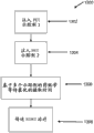
Figure 10 A and 10B are for calculating the conceptual description of EGRT method of the starting point of LOR; Figure 10 C is the flow chart in the example embodiment of the method shown in Figure 10 A.
Figure 11 A is for radiation being sent to a kind of conceptual description of variation of the EGRT method in oxygen-starved tissue region; Figure 11 B is the flow chart of the example embodiment of method shown in Figure 11 A.
Figure 12 A is for transmitting a kind of conceptual description of variation of the EGRT method of radiation along the crossing LOR of the PTV of positron emission activity with having reduction; Figure 12 B is the flow chart of the example embodiment of method shown in Figure 12 A.
Figure 13 is the flow chart that uses a kind of example of the EGRT method that surpasses a PET tracer.
Figure 14 A is the conceptual description along the example of the EGRT method with the crossing LOR application of radiation of a plurality of PTV; Figure 14 B is the flow chart of the example embodiment of method shown in Figure 14 A.
Figure 15 A is to have internal rack movably and the example schematic diagram of the EGRT system of the movably outside frame of separating to 15B; Figure 15 C is the flow chart that can how to use an example of the system shown in Figure 15 A and 15B.
Embodiment
Described herein is for locating the method and system about the radioactive source of one or more region-of-interests in coordinate system.In some changes, such system and method can be used to the transmit steering radiotherapy for the radiation transmission of the transmission path of the photon along from positron annihilation event.Method and system described herein can be used to the radiation of high dose to be sent to the first region-of-interest (for example, tumour), and a small amount of radiation (if any) is sent to the second region-of-interest (for example, surrounding tissue).Below described system and method accurately localizing objects tumor region so that high-grade radiation can be applied to (a plurality of) tumour and protection (a plurality of) tumour described tissue around.These system and methods can help to provide knub position accurately, and can be used to radiation wave beam to be sent in real time described target tumor region (for example,, within several seconds after positron annihilation transmission path has been detected).In order to provide the radiotherapy of use, these system and methods can process and managed source for example, from the uncertainty of a plurality of processes (, tumour body is described, patient's pendulum position and physiological movement).System and method described herein can help to improve radiotherapy effect, patient's comfort level and/or cost efficiency.Although with reference to the following described variation of EGRT system and example, should be appreciated that these are only the examples of system, this system can be used to location about the radioactive source of one or more region-of-interests in coordinate system.In coordinate system, region-of-interest can comprise, but be not restricted to, tumor tissues, non-tumor region, radiation-sensitive organ or structure, any anatomical structure, any transmitting positron (for example, crave for PET region) region or body, anyly (for example do not launch positron, non-ly crave for PET region) region, the region or the body that about craving for PET region, are defined, fixed area or body, moving area or body, by user or practitioner (for example, plan target body portion) or machine algorithm is (for example, image processing algorithm) any region identifying or body etc.
EGRT can be used alone or uses with together with the emitting treatment of other type.For example, EGRT can be used together with adjusting strong emitting treatment (IMRT) and/or image guiding emitting treatment (IGRT).IMRT can produce the distribution of high temporal dosage and retain health tissues to radiation is sent to target tumor region simultaneously.Before treatment plan, IGRT can with imaging mode, for example MRI or CT locate the described tumour in described patient.In order the location in real time in described target tumor region to follow the tracks of, by the one of these imaging techniques or be all combined with EGRT that to be useful guide described radiotherapy to assist in ensuring that at described object tissue regions place.
Disclosed herein is the system and method that uses the EGRT of PET tracer, and wherein radiation can be employed along the line of response (LOR) of the positron annihilation transmit path calibration overlapping with detecting.The system that can be used to EGRT can comprise: in patient region around movably frame, can be along one or more positron emission detectors of this machine frame movement and along this frame also one or more therapeutic radiation source movably.One or more positron emission detectors can detect and follow the tracks of for example, transmission path corresponding to a plurality of region-of-interests (, (a plurality of) tumour).The motion that one or more radioactive sources can be configured to compensate each tumour in a plurality of tumours is so that radiation can be applied to exactly (a plurality of) tumour and be shall not be applied to health tissues.For locating a kind of variation of the system (130) that can be used to the radiocurable radioactive source of transmit steering, at Fig. 1, be illustrated.System 130 can comprise: circular movable frames (not shown), be arranged on the radioactive source (131) in this frame, one or more positron annihilation emission sensor (133), one or more x ray detector (132), kinematic system (134) and controller or microprocessor (135) that is decided to be various positions in this frame or around.Described in x ray detector (132) and positron annihilation emission sensor (133) also can be installed in movably in frame.In some changes, described positron emission detector (133) and described x ray detector (132) can be disposed in around the solid part of periphery of described frame.Positron emission detector (133) can be configured to by the described transmission path (136) of the caused described photon of described annihilation events, detect positron annihilation event by perception.Kinematic system (134) can be configured to mobile described frame and about the auxiliary device of region-of-interest or target body portion (138) so that transmission path (136) calibration of described radioactive source (131) and described detection.Microprocessor (135) can be connected to described radioactive source (131), positron emission detector (133), x ray detector (132) and described kinematic system (134) to regulate each the motion each other of these parts, and so that with all parts in these parts of Sequential Activation of expectation.For example, described microprocessor (135) can be identified the described positron emission path (136) overlapping of intersecting with described target body portion (138), and described in tunable described calibration, configuration and the triggering of radioactive source to radiation is directed to described target body portion (138) along the transmission path (136) of described detection.
Microprocessor (135) can be controlled the rotation of described frame to regulate the orientation of described radioactive source (131) for the transmission path of a plurality of detections of response in the EGRT process of the course for the treatment of.The described microprocessor of EGRT system can comprise computer-readable storage medium, and can carry out various functions according to the software or the firmware that are stored in this computer-readable storage medium.The example of computer-readable storage medium can comprise: but be not restricted to, electricity, magnetic, light, electromagnetism, ultrared or semiconductor system, device or equipment, portable computer disk (magnetic), random access storage device (RAM) (magnetic), read-only memory (ROM) (magnetic), programmable and erasable read-only memory (EPROM) (magnetic), portable CD for example CD, CD-R, CD-RW, DVD, DVD-R or DVD-RW or flash memory for example compact flash, safe digital card, USB memory device, memory stick, etc.Software or firmware also can pass through or combined command executive system, device or equipment, for example computer based system, the system that comprises processor or other system that can obtain described instruction and carry out this instruction from this instruction execution system, device or equipment are propagated for use in any transmission medium.The example of transmission medium can comprise: but be not restricted to electricity, magnetic, light, electromagnetism or ultrared or wired or wireless communication media.
Although the system and method for EGRT described herein can be configured to detect and response from the transmission path of positron annihilation transmit events that results from the coincidence of PET tracer, the radiotracer of other type also can be used to EGRT.For example, EGRT system and method can be additionally or is alternatively configured to detection and responds the single photon emission that results from SPECT tracer.Other radiotracer often being used in nuclear medicine also can be used together with EGRT system and method described herein.The line of departure from such radiotracer can be used as accurately and approaches the guiding that real-time tumour is followed the tracks of.The type that relies on the radiotracer using, EGRT system can comprise multiple detector, for example positron emission detector, single photon emission detector etc.EGRT system also can comprise multiple therapeutic radiation source, comprise linear accelerator, emissivity material, x radiographic source, particle beam source, etc.In some changes, radioactive source can comprise collimater, and this collimater can transmit radiation for response single photon event.A kind of example that can be used for the system of EGRT is that the patent No. of registration on November 29th, 2004 is to be described in 7,265,365 United States Patent (USP).The other description of EGRT system and example below, and be to be provided in U.S. Patent application that the publication number of on February 9th, 2009 registration is 2009/0256078, its full content is contained in this by reference.
Method for EGRT can be used to the position of tracking of knub in real time, and/or can be used to the radiation of desired amount to be sent to (a plurality of) tumour in plan target body portion (planning target volume, PTV), protects surrounding tissue simultaneously.PTV can be before treatment and/or plan course for the treatment of during by doctor and/or technical staff (for example, transmitting tumour expert, medical physicist, line of departure scholar, emitting treatment doctor, etc.) use multiple imaging mode (for example CT, PET, MRI, x ray, etc., or separately or combination) determined.PTV also can be determined during emitting treatment course for the treatment of.For example, PTV can during emitting treatment course for the treatment of, use one or more types airborne imaging mode (for example, CT, PET, MRI, x ray, etc., or separately or combination), periodically determined.About the data of PTV, can be stored in the described microprocessor of EGRT system for medical physicist and/or emitting treatment doctor and use during emitting treatment course for the treatment of.PTV can comprise described tumor region and in this tumor region nonneoplastic tissue around, or PTV can only include the tumor region that there is no described nonneoplastic tissue around.Alternatively or additionally, PTV for example can comprise, as the growth of the determined viewing area of the imaging mode by selecting (, CT, PET, MRI, x ray, SPECT, etc.) and tumour.In some cases, PTV can comprise crave for PET tissue regions (for example, by PET tracer, occupied and launched the body of organizing of the photon that caused by positron annihilation), and in other situation, PTV can not only comprise and craves for PET region but also comprise the contiguous non-PET of craving for tissue regions.In some changes, PTV can comprise the above-mentioned described outer peripheral region of one or more volumes that has, for example, and patient and/or organ movement, organ profile and size variation, and the probabilistic edge in radiation beam alignmetn.
Some method can contribute to compensation owing to breathing or other patient moves the tumour and/or the PTV that cause and moves, and/or be provided for more accurately or accurate borderline tumor detects, and/or the radiation that for example, contributes to guarantee to be applied to PTV by reducing " heat " or " cold " point (, described radiological dose being transmitted equably by whole PTV) in PTV is homogeneity.Although the whole bag of tricks for EGRT is being described below respectively, the one or more methods in method described herein of should be appreciated that can be at EGRT before the course for the treatment of or during combined.Alternatively, the one or more methods in these methods of EGRT can be in patient's cancer treatment procedure and the use that combines of operation, chemotherapy, brachytherapy and/or other cancer therapy.
A kind of variation of the method for EGRT can be sent to radiation-sensitive structure by the radiation that reduces dosage and the radiation of prescribed dose is sent to the tumour that is arranged in PTV simultaneously.Some variation of such method can avoid the radiation of any dosage to be sent to the tissue regions of selection or any radiation-sensitive structure.Radiation-sensitive structure can be for example, to be easy to especially be subject to the organ of radiation damage.Radiation-sensitive structure can comprise heart, esophagus, rectum, stomach, intestine and small intestine, chest, be included in salivary gland organ, backbone and other nerve fiber in gamete, etc.In some variation of EGRT, radiation-sensitive structure alternatively available radiation protection medicine (for example, Amifostine (amifostine)) is processed, and it contributes to any radiation damage of these radiation-sensitive structure self-regenerations.A kind of variation that the dosage radiation of reduction is sent to the method for radiation-sensitive structure can comprise radiation along the positron annihilation transmission path that overlap crossing with described radiation-sensitive structure or transmission continually of LOR.Figure 1A illustrates the patient region (100) with plan target body portion (102) and radiation-sensitive structure (104) conceptually.At least a portion of PTV has occupied PET tracer (for example, FDG, FLT, F-MISO), and may launch the photon causing due to positron annihilation event, and for example, at least a portion of this PTV can be to crave for PET.Originating from transmission path in described PTV or line of response (for example line of response (106)) can intersect with described radiation-sensitive structure (104), and described in other, transmission path or line of response (for example line of response (108)) do not intersect with this radiation-sensitive structure (104).Radioactive source (not shown) specifically frequency and intensity along described LOR(108) application of radiation is to be sent to described PTV(102 by prescribed dose).Radioactive source can be along described LOR(106) application has been attenuated or regulated the radiation of (for example,, in frequency and/or intensity) to reduce this radiation exposure to described radiation-sensitive structure (104).For example, the mode that frequency (using this frequency to be transmitted along described LOR radiation) can probability is lowered.Alternatively or additionally, and along described LOR(108) the described radiation that transmits compares, along described LOR(106) the described radiation that transmits can be attenuated (for example, reducing intensity or power).
The exit dose of reduction is sent to a kind of example that radiation-sensitive structure is sent to prescribed dose radiation the method (110) of PTV simultaneously roughly to be provided in Figure 1B.Method (110) (for example) can reduce described frequency, and the radiation with this frequency is along being employed with the crossing LOR of radiation-sensitive structure.This method can be with comprising movable frames, implementing along one or more positron emission detectors of this frame, the EGRT system that is arranged on one or more radioactive sources, kinematic system and microprocessor in this frame.Process LOR(112) can comprise that using positron emission detector to detect substance closes positron annihilation transmission path, and for example can be included in alternatively storage in the memory of described microprocessor, about the data of this LOR (, position data, signal strength data, etc.).Subsequently, whether microprocessor can intersect at PTV(114 by the position data of described LOR is compared to assess described LOR with the position data that is stored in the PTV in the memory of described microprocessor).If non-intersect, described EGRT system can turn back to initial condition (112) and detect another LOR.If intersected, described microprocessor can compare to assess described LOR by the position data of the position data of described LOR and described radiation-sensitive structure and whether intersect at radiation-sensitive structure (116).If non-intersect, described microprocessor can think that the radioactive source of described EGRT system sends instruction so that along LOR(122) application of radiation.If intersected, described microprocessor can produce the digital X(118 between 0 to 118 randomly).Then, described microprocessor determines that described digital X is whether lower than the probability threshold T(120 of pre-programmed).If be not less than, so described EGRT can turn back to described initial condition (112) and detect another LOR.If the digital X of described adjusting is lower than pre-programmed thresholding T, so described microprocessor can send instruction so that along described LOR(122 to described radioactive source) application of radiation.Once radiation is transmitted along the LOR of described detection, if need so described method (110) to be repeated, for example, until the radiation of prescribed dose has been applied to described PTV and/or described radiation-sensitive structure.As example, regulation to the dosage of radiation-sensitive structure be no more than tissue around described and/or PTV dosage level other 20% may wish.In this example, described probability threshold T can be selected as 0.2, so that radiation is sent to 1/5th in crossing line of response all with described radiation-sensitive structure and described PTV.Alternatively, probability threshold T also can represent decay or spreading coefficient, by radiating described in decay or spreading coefficient, is conditioned.For example, along can being regulated by the described probability threshold of T=0.2 with the described radiation that all crossing LOR is employed of PTV and radiation-sensitive structure, make this radial applications be in normal intensity level other 20%.Alternatively, the nominal leaf of described radioactive source (leaf-open) time of opening may be 20% of this nominal leaf ETAD expected time of arrival and departure.Probability threshold T can be any suitable value, for example, 0,0.005,0.01,0.05,0.10,0.5,0.75,0.9,1.0 etc.In other changes, the intensity of the described radiation being employed along LOR or power are decayed by probability coefficent or are expanded.Probability coefficent can by be less than described thresholding T 0 and 1 between random generation number obtain.
Fig. 1 C to 1E be when described method (110) be implemented in case application of radiation to PTV(140) time, represent the contour map of Computer Simulation radiological agent spirogram.At Fig. 1 C, to different contour in 1E, there is uniform contour interval and be reflected in the effect that changes described probability threshold T on the exit dose that is applied to radiation-sensitive structure (142).Fig. 1 C illustrate when described probability threshold T=1.0(for example, punishment does not deliver a dose to described radiation-sensitive structure) time dosage section line chart.In this example, to the described radiological dose of described radiation-sensitive structure (142), be similar to the described radiological dose of surrounding tissue.Fig. 1 D illustrates dosage section line chart when described probability threshold T=0.2, and Fig. 1 E illustrates dosage section line chart when described probability threshold T=0.0.When described probability threshold T is during to 0 minimizing, as described in as shown in contour map, to all dosage of described radiation-sensitive structure (142), can reduce.
In other of EGRT method changes, the characteristic of described radiation wave beam that described radioactive source is adjustable is sent to described PTV is to be sent to the non-PET of the craving for tissue in described PTV by radiation.For example, the width of described radiation wave beam can be expanded to radiation is sent to the non-PET of the craving for tissue in described PTV, and/or a plurality of radiation wave beam can be used in the non-PET of the craving for tissue in described PTV in a period of time.An example of this method is illustrated conceptually in Fig. 2 A.This method can be included in to be obtained image (for example, one or more in CT, MRI, PET etc., comprise PET-CT image) during the treatment plan stage and is defined in during EGRT the described plan target body portion or the body that are treated.Expansion PTV(202) edge can be expanded from the width for edge (W1) of the described PET of craving for target body portion (204).During EGRT course for the treatment of, when intersecting described PTV(202) LOR(206) while being detected by positron emission detector (not shown), radiation wave beam (208) by described radioactive source (210) application can be conditioned, so as described radioactive wave beam width (W2) be described in increasing, crave for PET body (204) and PTV(202) between the direction at edge on be wider.In some changes, if described radiation wave beam (208) is basically perpendicular to the propagation direction at described edge, the width of so described radiation wave beam (W2) can be expanded in the direction at described edge.
A kind of example of method of radial applications being craved for to the tissue on PET body border in being adjacent in PTV is illustrated in Fig. 2 B and 2C.Fig. 2 B is illustrated in the method (220) that can be used during treatment plan, and the method can be carried out before the course for the treatment of at described EGRT, or can during EGRT course for the treatment of, carry out.Described method (220) can comprise obtains (220) one or more images, for example CT, MRI, PET and/or comprise PET-CT image.(a plurality of) image based on obtaining, (a plurality of) PTV can crave for PET region by location and define.Alternatively, the extending edge of craving for PET body described in any surpassing is definable also, and for example, (a plurality of) PTV can comprise and craves for PET tissue and be adjacent to the non-PET of the craving for tissue that this craves for PET tissue.In some changes, (a plurality of) treatment body and/or surpass described in crave for image processing algorithm and/or the doctor that the extending edge of PET body can be carried out by other patient data, computer and input to define, and can have and surpass length and the width that (a plurality of) crave for the edge of PET body.About the extending edge on the border of the described information of craving for PET body and/or definition PTV (for example, length, width, body, about the direction of the described extending edge of described target body portion, etc.) can be stored in the memory of microprocessor of EGRT system for using during treatment course for the treatment of.
Fig. 2 C illustrates the information that can use from described method (220) and radiotherapy is offered to a kind of example of patient's EGRT method (230).This method can be implemented by above-mentioned EGRT system described and that further describe below.Imaging crave for PET body and from the extending edge data of described method (220) (for example, length, width, body, about the direction of the extending edge of described target body portion, etc.) can before the course for the treatment of, be stored in the memory of microprocessor of described EGRT system at described EGRT.Alternatively or additionally, extending edge for example, can be determined or be calculated by obtaining one or more images (CT, MRI, PET and/or comprise synthetic PET-CT image) during treating any during the described course for the treatment of by described EGRT system.Process LOR(232) can comprise that using positron emission detector to detect substance closes positron annihilation transmission path, and for example can be included in alternatively storage in the memory of described microprocessor, about the data of described LOR (, position data, signal strength data, etc.).Subsequently, whether described microprocessor can intersect at PTV(234 by the position data of the position data of described LOR and described PTV is compared to assess described LOR).If non-intersect, described EGRT system can turn back to described initial condition (232) and detect another LOR.If intersected, described microprocessor can use and from the data of described method (220), calculate (236) described LOR and whether be basically perpendicular to described extending edge direction.If out of plumb, described microprocessor can send instruction so that along LOR(268 to the radioactive source of described EGRT system) application of radiation.If described LOR is to be basically perpendicular to described extending edge direction by calculating, so described microprocessor can send instruction to transmit (240) radiation wave beam along described LOR to radioactive source, and wherein said radiation wave beam has the width corresponding to described extending edge width.In some changes, described extending edge can be calculated by the microprocessor of described EGRT system during the described course for the treatment of, and can be used alone or use together with any extending edge that can be determined during the treatment plan stage.Once radiation is transmitted along described LOR, if need so described method (230) to be repeated, for example, until the radiation of prescribed dose has been applied to described PTV.
Some variation of EGRT method can be distinguished and originates from the positron annihilation transmission path of the coincidence of planning target body portion and originate from the transmission path outside this plan target body portion.Positron annihilation event can occur PTV is outside, and the enhancing of some PET tracer (for example FDG) picked-up may occur, for example, and in infected zone or other structural region of heart, brain, areas of inflammation, lung.For example, described PET tracer can be organized and occupy in a plurality of positions, and EGRT only can be planned subset for these positions (for example, some crave for PET tissue may be suitable for the target of radiation and other to crave for PET tissue may be to be not suitable for).Fig. 3 A illustrates to be had first and craves for the patient region (300) that PET body (302) and second is craved for PET body (304).In this example, described first to crave for PET body (302) may not be a part of PTV.Second craves for PET body (304) may be positioned at PTV.The method that there is no to distinguish the EGRT originate from the positron annihilation transmission path of the coincidence in PTV and to originate from the transmission path outside this PTV may will craved for the radiological dose of application enhancing in the direction of PET joint area described in this PTV and this PTV outside.Mode wherein EGRT method can avoid creating a regional area for higher radiation relatively, can be included as each orientation that therapeutic radiation source may occupy and calculate the mathematical projection of craving for PET body of described PTV outside.For example, first crave for PET body (302) may be in position 307 places have the projection (306) of radioactive source.The similar projection of craving for PET body of PTV outside can be the position of the one or more radioactive sources in the frame of EGRT system and calculates.In some changes, the projection of described calculating can be used to regulate launch time or intensity or the number of times of the described radiation transmitting along each path, and the launch time of described radiation or intensity or number of times are inversely proportional to described projection value on ad-hoc location.For example, when different path comparison from by described PTV, the craving for PET region and may cause there is higher relative projection value along the path by this PTV of described PTV outside.Radioactive source can transmit radiation according to the projection value calculating.For example, at the projection value of the enhancing of the specific location of frame, may indicate described therapeutic radiation source from that position, than the projection value reducing, may indicate described therapeutic radiation source from that position, transmit the still less radiation of ratio.Radiation transmits and can regulate by different way, for example, and with time, intensity or the number of times along described transmission path transmitting.
Avoid a kind of example of method (310) of foundation of the regional area of high radiation roughly to provide in Fig. 3 B.Method (310) regulates according to the projection of " focus " of the position at described radioactive source the described radiation being employed along LOR.This method can be with comprising frame movably, along one or more positron emission detectors of this frame, along the EGRT system of one or more radioactive sources, kinematic system and the microprocessor of this frame, implement.Process LOR(312) can comprise that using positron emission detector to detect substance closes positron annihilation transmission path, and for example can be included in alternatively storage in the memory of described microprocessor, about the data of described LOR (, position data, signal strength data, etc.).Subsequently, whether microprocessor can intersect PTV(314 by the position data of described LOR and the position data that can be stored in the described PTV in the memory of described microprocessor are compared to assess described LOR).If non-intersect, EGRT system can turn back to described initial condition (312) and detect another LOR.If intersected, microprocessor can calculate modulation factor, and this modulation factor is inversely proportional to not at described PTV(316) in the projection in one or more PET of craving for region.The modulation factor calculating can be used to regulate frequency, work period, intensity, emitting times and/or other characteristic of described radiation wave beam.Then, microprocessor can provide instruction to regulate described radiation wave beam according to described modulation factor to described radioactive source.Then, radioactive source can transmit along described LOR the radiation of (318) described adjusting.Once radiation is transmitted along the LOR of described detection, if need so described method (310) to be repeated, for example, until the radiation of prescribed dose has been applied to described PTV.
Some method of EGRT can compensate any decay of the LOR signal strength signal intensity that may occur due to the variable density in described patient region.Fig. 4 A illustrates conceptually to have and craves for PET body (401) and the patient region (400) of high-density region more.High-density region may be due to the prosthese of exist implanting, have the organ of Geng Gao tissue density, for example bone (404), etc.For example,, with the crossing LOR(402 of described skeletal structure (404)) may than not with any bone or the crossing LOR(406 of high-density region) decay more.Various imaging modes can be used to the described decay of the described signal strength signal intensity of approximate calculation LOR.In some variation of EGRT, KV level CT image can be used to estimate and compensate the described decay of described LOR signal.Described LOR decay also can be calculated based on other imaging mode, for example conical beam CT, MRI, X ray etc.The estimation of the described decay of LOR signal can be carried out at programming phase or before the course for the treatment of or during radiation therapy session.In some changes, the described decay of LOR signal can be used PET or x radial imaging technology dynamically to be calculated during described radiation therapy session.Then, radiation wave beam can be conditioned to compensate LOR signal attenuation according to the described decay of described LOR signal, so that the exit dose of calibration is sent to described PTV, limited radiation is simultaneously sent to health tissues.In some cases, along the LOR application booster stage of decaying, other radiates to compensate described influence of fading and contributes to guarantee that described PTV receives other radiation for the treatment of level of signification and may wish.In other cases, the high-density region of the described LOR that wherein decays is radiation-sensitive structure, falls low-level radiation reduce or limit the described radiation that is sent to described high-density region and may also wish along that LOR application.For example, the skeletal structure LOR signal of can decaying, and can be lowered to limit along the described radiation of the LOR application of described decay the described radiation that is sent to this skeletal structure.Radiation wave beam can be conditioned, for example, by increase or reduce the described decay of amplitude or the frequency of the LOR signal that compensates described detection in amplitude or frequency.Alternatively or additionally, radiation wave beam can the time (for example, work period) and/or intensity regulate.This adjusting can the density projection by this LOR of described patient's All Paths along LOR by estimation, that projection is estimated (for example to convert LOR positron energy to, and regulate time of described radiation response or intensity so that the exit dose compensation transmitting is implemented along the overall attenuation in this LOR path 511 kilo electron volts).
In Fig. 4 B, roughly provide calibration or compensation LOR signal attenuation so that enough exit doses are applied to a kind of example of the method for described PTV.Method (410) regulates the radiation being employed along LOR, and it compensates measured decay in described LOR signal.This method can use comprise frame movably, along one or more positron emission detectors of this frame, be implemented along the EGRT system of one or more radioactive sources, kinematic system and the microprocessor of this frame.Process LOR(412) can comprise that using positron emission detector to detect substance closes positron annihilation transmission path, and for example can be included in alternatively in the memory of described microprocessor storage, about the data (, position data, signal strength data etc.) of this LOR.Subsequently, whether microprocessor can intersect PTV(414 by the position data of described LOR and the position data that can be stored in the PTV in the memory of described microprocessor are compared to assess described LOR).If non-intersect, described EGRT system can turn back to described initial condition (412) and detect another LOR.If intersected, the decay that described microprocessor can be based on could previously being inputted and/or be stored in KV level in the memory of described microprocessor or megavolt level CT image and calculating (416) described LOR.The described decay of LOR signal can be used to calculate pad value (418), and this pad value (418) can be used to regulate described radiation wave beam.In some changes, the pad value calculating can reduce or increase the adjustable described radiocurable average energy of described exit dose in the amount of LOR signal attenuation by passing ratio, so that the exit dose of described calibration is transmitted along the LOR of described decay.Then, microprocessor can provide instruction to regulate described radiation wave beam according to the pad value of described calculating to described radioactive source.For example, described radiation wave beam can direct proportion in or be inversely proportional to described attenuation coefficient and be conditioned.Then, described radioactive source can transmit the radiation of (420) described adjusting along described LOR.Once radiation is transmitted along the LOR of described detection, if need so described method (410) to be repeated, for example, until the radiation of prescribed dose has been applied to described PTV.
A kind of variation of the method that can use together with EGRT system can be used for radiation to be sent to a plurality of plan target body portion.Described method can comprise the positron emission activity detecting from a plurality of plan target body portion, then along intersecting at the LOR that plans each detection of target body portion described at least one, applies one or more radiation wave beams.EGRT system and this method can be by approaching in real time (for example, several seconds after LOR is detected within) responds any movement that described LOR compensates each plan target body portion in described plan target body portion, and no matter the correlation that they move.For example, after described LOR is detected, radiation wave beam can be less than 5 seconds, 4 seconds, 3 seconds, 2 seconds, 1 second or along the LOR detecting, be employed for 0.5 second.Figure 14 A illustrate a kind of example wherein patient region (1400) in a PTV, have along arrow (1404) mobile first crave for PET region (1402) and in the 2nd PTV, have along arrow (1408) mobile second crave for PET region (1406).The first and described second movement of craving for PET body can be associated or not associated.LOR(1410), (1412) and (1414) representative intersects at the LOR of at least one the plan target body portion in described plan target body portion.EGRT system can be along LOR(1410) one or more radiation wave beams are applied to described first crave for PET region (1402), and/or along LOR(1412) one or more radiation wave beams are applied to described second crave for PET region (1406), and/or along described LOR(1414) radiation wave beam had not only been applied to described first craves for PET region but also be applied to described second and crave for PET region and crave for PET region to the radiation of prescribed dose is sent to described first and second.
In Figure 14 B, roughly provide a kind of example that radiation is sent to the method (1420) of a plurality of plan target body portion.This method can use comprise frame movably, along one or more positron emission detectors of this frame, be implemented along the EGRT system of one or more radioactive sources, kinematic system and the microprocessor of this frame.Process LOR(1422) can comprise that using positron emission detector to detect substance closes positron annihilation transmission path, and for example can be included in alternatively storage in the memory of described microprocessor, about the data of this LOR (, position data, signal strength data, etc.).Subsequently, this microprocessor can be by by the position data of described LOR and a described PTV(1424) position data compare to assess described LOR and whether intersect a PTV(1424).If intersected, so then, described microprocessor can provide instruction so that along described LOR(1428 to described radioactive source) application of radiation.If LOR does not intersect with a PTV, whether so described microprocessor can intersect at the 2nd PTV(1426 by the position data of the position data of described LOR and described the 2nd PTV is compared to assess described LOR).If intersected, microprocessor can provide instruction so that along described LOR(1428 to described radioactive source so) application of radiation.If non-intersect, so described EGRT system can turn back to described initial condition (1422) and detect another LOR.Once radiation is transmitted along the LOR of described detection, if need so described method (1420) to be repeated, for example, until the radiation of prescribed dose has been applied to the described first and/or second plan target body portion.
Some variation of EGRT method can be used to help described brachytherapy sources at described PTV place, accurately to guide radiation wave beam.A kind of example of such method is shown in Fig. 5 A conceptually, wherein by the patient of patient region (500) representative, is positioned at the core of the frame (502) of EGRT system.The LOR(503 being detected by positron emission detector) can be first evaluated so that definite described LOR(503) whether with PTV(504) intersect.In some cases, when radioactive source (506) is placed on the limited distance away from the LOR detecting, this radioactive source (506) can be launched radiation wave beam (508).At PTV(504) in specified point (507), described radiation wave beam (508) can be directed, this can contribute to calibrate described LOR(504) and described radiation wave beam (508).Point (507) can be the mid point of the line segment that forms of the joining by described PTV and described LOR.For example, by identifying first wherein said LOR through the border of PTV, identification second point wherein this LOR at the second place place on this border through this PTV, connect and second point at this first to determine a line segment, point (507) can be calculated.Described point (507) can be the mid point of the line segment of described definition.Alternatively, described point (507) can be any another position in described PTV.
In Fig. 5 B, be roughly given in a kind of example that specific location in PTV accurately guides the method (510) of radiation wave beam.Method (510) guides described radioactive source so that the midpoint application of radiation wave beam of the line segment forming at the intersection point by described LOR and described PTV.This method can be with comprising frame movably, along one or more positron emission detectors of this frame, along the EGRT system of one or more radioactive sources, kinematic system and the microprocessor of this frame, implement.Process LOR(512) can comprise that using positron emission detector to detect substance closes positron annihilation transmission path, and for example can be included in alternatively storage in the memory of described microprocessor, about the data of this LOR (, position data, signal strength data, etc.).Subsequently, microprocessor can be by by the position data of described LOR and described PTV(514) position data compare to assess described LOR and whether intersect at this PTV(514).If non-intersect, so described EGRT system can turn back to described initial condition (512) and detect another LOR.If intersected, so described microprocessor can calculate the mid point of the line segment that (516) consist of the intersection point of described LOR and described PTV.Then, microprocessor can provide instruction so that the described mid point that guiding and application (518) radiation wave beam extremely calculate in abovementioned steps to described radioactive source.Once radiation is transmitted along the LOR of described detection, if need so described method (510) to be repeated, for example, until the radiation of prescribed dose has been applied to described PTV.
Other variation of EGRT system can comprise that a plurality of points from a plurality of positions and/or during time transmit radiation to respond single LOR.As example, radiation wave beam can be transmitted any one end along described LOR from this LOR, or is transmitted in the different time from same LOR end points.Fig. 6 A and 6B illustrate a kind of example how a plurality of radiation wave beams can be employed along LOR conceptually.Fig. 6 A illustrates and is arranged in frame (602) and has PTV(604) the patient who craves for PTV region (600).Originate from described PTV(604) in LOR (606) along described frame (602), in primary importance (608) and the second place (610), locate to be detected.Radioactive source (612) can be moved so that along described LOR(606 in various orientation along described frame) radiation wave beam is applied to described PTV(604).For example, as shown in Figure 6B, radioactive source (612) can be moved to described primary importance (608) so that along described LOR(606) the first radiation wave beam (614) is applied to described PTV(604).Additionally or alternatively, as shown in Figure 6 C, radioactive source (612) can be moved to the described second place (608) so that along described LOR(606) the second radiation wave beam (616) is applied to described PTV(604).In some changes, a plurality of radiation wave beams can be along the described LOR(606 that is positioned at single orientation) from described radioactive source (612), be employed.
Specific location in PTV accurately guides a kind of example of the method (620) of radiation wave beam roughly to provide in Fig. 6 D.Method (620) guides described radioactive source so that from one or more end-point applications radiation wave beams of the LOR that detects.This method can be with comprising frame movably, along one or more positron emission detectors of this frame, along the EGRT system of one or more radioactive sources, kinematic system and the microprocessor of this frame, implement.Process LOR(622) can comprise that using positron emission detector to detect substance closes positron annihilation transmission path, and for example can be included in alternatively storage in the memory of described microprocessor, about the data of this LOR (, position data, signal strength data, etc.).Subsequently, described microprocessor can be by by the position data of described LOR and described PTV(624) position data compare to assess described LOR and whether intersect at this PTV(624).If non-intersect, so described EGRT system can turn back to described initial condition (622) and detect another LOR.If intersected, so described microprocessor can provide instruction to transmit (626) first radiation wave beams along described LOR from primary importance to described radioactive source.Then, microprocessor can provide instruction so that wave beams are radiated in application (628) second along described LOR from the second place to described radioactive source.Alternatively, a plurality of radiation wave beams can be transmitted from same position along described LOR.Once radiation is transmitted along the LOR of described detection, if need so described method (620) to be repeated, for example, until the radiation of prescribed dose has been applied to described PTV.
The another kind of method changes the strong emitting treatment of tune capable of being combined (IMRT) and EGRT to radiotherapy is sent to plan target body portion.If it is low that the positron annihilation overlapping transmits, if or of short duration treatment time wishes, the IMRT-EGRT method of mixing may be useful so.In some changes, IMRT and EGRT plan before may having treatment separately, and during described radiotherapy, IMRT can be used to as transmitting radiation wave beam a part of course for the treatment of of the described course for the treatment of, and EGRT can be used to another part transmission course for the treatment of radiation wave beam into the described course for the treatment of.For example, for each orientation of the described radioactive source along described frame, first described radiation wave beam can be used IMRT then to use EGRT(or first use EGRT then to use IMRT) apply.During described emitting treatment course for the treatment of, for one or more radioactive sources orientation, some method can replace between IMRT and EGRT.
In Fig. 7, roughly provide a kind of example of mixing IMRT-EGRT method (700).Method (700) can use IMRT and two kinds of technology of EGRT by radial applications in PTV.Method (700) use comprise frame movably, along one or more positron emission detectors of this frame, can be implemented along the EGRT system of one or more radioactive sources, kinematic system and the microprocessor of this frame.Described radioactive source can be moved to the primary importance along described frame, and in particular chassis angle (702).In some changes, arranging of frame angle can be separated equably around circular frame, yet in other variation, the spacing of described frame angle may be inhomogeneous.In each frame angle position, described microprocessor about the data of a plurality of LOR from (a plurality of) positron emission detector (for example can receive, position data, signal strength data, etc.), and can calculate (704) or estimation IMRT or EGRT and whether should be used to radiation to be sent to described PTV(706 based on being stored in model pre-programmed or predetermined in described microprocessor).Use EGRT, whether this decision can be based on having enough LOR data to respond.If IMRT is selected, microprocessor can offer described radioactive source by instruction to will radiate transmission (708) to whole PTV so.If select EGRT, microprocessor can be assessed described LOR and whether intersect at PTV(710).If non-intersect, so described EGRT system can turn back to described initial condition (702) and process next frame angle.If intersected, described microprocessor can offer described radioactive source by instruction to transmit radiation wave beam (712) along described LOR.Use IMRT or EGRT, once radiation is transmitted, so described radioactive source can be moved to another position, and if need described method (700) to be repeated, for example, until the radiation of prescribed dose has been applied to described PTV.
In the another kind of EGRT method changes, described method is upgraded the position of described PTV and/or the step of direction during can being included in described treatment course for the treatment of.For example, the barycenter of described PTV can be redefined to consider during described treatment any tumour that (for example, due to the change of variation, metallaxis, wriggling or the patient position of patient's breathing patterns, etc.) may occur and moves.Fig. 8 A and 8B are illustrated in conceptually initial orientation place and have PTV(802) patient region (800) and at described PTV(802) in the tumour (804) at initial orientation place.The time point more early of the described initial orientation of PTV and tumour in the course for the treatment of before treatment or during described radiation therapy session can be measured.In radiation therapy process, the orientation of described PTV may need to be moved, for example, and to the orientation shown in Fig. 8 B.As shown in Figure 8 B, described PTV can be redefined the new scope of activities that reflects described tumour (808) for second orientation (806).In some examples, the barycenter of described PTV can be redefined according to the mean activity scope of described tumour.Additionally or alternatively, the described PET signal data of PET image based in the previously time interval (for example, last 0.5 second, 1 second, 2 seconds, 10 seconds, 20 seconds, 50 seconds, 60 seconds, 90 seconds, etc.) can be rebuilt, and be used to the described PTV of conversion (translation, rotation, be redirected, stretch or shrink, etc.).Some EGRT method can comprise based on respect to described timebase or with respect to the change of the barycenter of the temporary transient fuzzy reconstruction PET image of the PET image of last reconstruction, redefine the step of described PTV barycenter.
Shown in Fig. 8 C, upgrade periodically a kind of example of EGRT method (810) in the orientation of described PTV.The every orientation that can upgrade described PTV for 30 seconds of method (810), but should be appreciated that any update cycle can be as required (for example, for example, 0.5 second, 1 second, 2 seconds, 10 seconds, 20 seconds, 50 seconds, 60 seconds, 90 seconds, etc.) selected.Method (810) use comprise frame movably, along one or more positron emission detectors of this frame, can be implemented along the EGRT system of one or more radioactive sources, kinematic system and the microprocessor of this frame.After EGRT treatment (812) starts, the data of described microprocessor before based on treatment or fall into oblivion transmitting data from the nearest positron emission of last 30 seconds and can rebuild (814) initial or new PET image.PET data and/or image can be stored in the memory of described microprocessor.Then, microprocessor, by the position data in the previous orientation of the position data in the current orientation of described PTV and described PTV is compared, can determine whether the current orientation of (816) described PTV changes from the previous orientation of described PTV.If do not changed, so not as discussed previously, microprocessor can offer described radioactive source by instruction so that along the LOR application of radiation wave beam detecting, and EGRT can work on (818) then.If changed, the orientation of PTV can be updated (820) in the memory of described microprocessor so.Then, microprocessor can determine whether the described LOR detecting is positioned at the PTV of described renewal by the PTV positional information of upgrading.EGRT can work on (818).Once radiation is transmitted along described LOR, if need so described method (810) to be repeated, for example, until the radiation of prescribed dose has been applied to described PTV.
Some variation of EGRT method can be used to reduce or avoid the peak value of radiological dose, and the peak value of this radiological dose may appear at other the center of craving for uniformly PET body (for example, " back projection's impact " (backprojection effect)).Because intersect at the LOR of the body at the center of craving for PET body described in approaching, than those, intersect at the LOR that craves for the border of PET body described in this and can be detected more continually, so this impact may occur.EGRT method can be used filtered back projection (filtered-backprojection) technology to reduce or eliminate the radiation peak value in craving for PET region.Fig. 9 A illustrate conceptually can be used to calculate with substantially uniformly density can launch the method for the one dimension mathematical projection (902) of craving for PET body (900) of photon, wherein said projection (902) intersects at the quantity that the positron annihilation of coincidence of the particular orientation of described radioactive source launches and calculates by counting.The suitable filter using in filter back-projection algorithm (904) for the mathematical projection of calculating (902) (for example, Ram-Lak filter, Shepp-Logan filter or other can be used to the filter of image reconstruction) can be filtered by mathematics Shangdi.The result of described filtering projection can cause negative value, and this negative value can be calibrated (for example, being set to zero) and obtain rear filtering projection (post-filtered projection) (906).Then, rear filtering projection (906) can be used to regulate described radiation wave beam to crave for the more uniform radiant of PET body described in being applied to and be transmitted.For example, the intensity of the radiation of described transmission, and/or the time domain of the radiation of described transmission, may be directly proportional to described rear filtering projection (906).
Shown in Fig. 9 B, can be used to application and reduce or eliminate a kind of example of EGRT method (910) of the radiation of the radiation peak value in craving for PET region.This method use comprise frame movably, along one or more positron emission detectors of this frame, can be implemented along the EGRT system of one or more radioactive sources, kinematic system and the microprocessor of this frame.Process LOR(912) can comprise that using positron emission detector to detect substance closes positron annihilation transmission path, and for example can be included in alternatively storage in the memory of described microprocessor, about the data of this LOR (, position data, signal strength data, etc.).Subsequently, described microprocessor is assessed described LOR and whether is intersected at PTV(914).If non-intersect, so described EGRT system can turn back to described initial condition (912) and detect another LOR.If intersected, so described microprocessor estimation (916) angle, should be conditioned to the radiation of LOR described in this angular response.As shown in Figure 9 A, microprocessor can calculated dose distribution, and projection regulates described radiation response based on Ram-Lak filtering PTV, and negative value is calibrated to zero.Then, microprocessor can offer instruction described radioactive source and regulate described radiation wave beam according to described rear filtering projection.Then, radioactive source can transmit along described LOR the radiation of (918) described adjusting.Once radiation is transmitted along the LOR of described detection, if need so described method (910) to be repeated, for example, until the radiation of prescribed dose has been applied to described PTV.
The another kind of method that can be used in EGRT can transmit and distribute to positron emission or photo emissions distributes real-time or approaches the radiological dose that real-time measured intensity is directly proportional and pass through the patient's body being treated.This method can with have positron emission and/or the single photon emission detector that detects transmission path, use together with thering is collimater and mould the EGRT system of radioactive source of the described radiation wave beam that is applied to described PTV.The positron annihilation transmitting overlapping and/or the distribution of SPECT signal can be associated with other physiology or function aspects of the cell proliferation (increased cellular proliferation) of anoxic zones, enhancing or the patient's body being treated.For example, as shown in Figure 11 A, at special time (T1), in the primary importance place tumour (1100) of advancing the speed that may show as emissivity tracer uptake, may there is subregion (1102).Described tumour and/or described subregion may move that to make at time (T2) described subregion (1104) may be the second place place in described tumour (1100).In some cases, these subregions that make radiological dose progressively expand described patient's body to wish, this can comprise the activity of following the tracks of these subregions.Some variation of this method can be used one or more PET tracers (for example FDG, F-MISO, FLT, F-ACBC, Cu-ATSM, etc.), and one or more SPECT tracers (for example Tc-99m-tagged compound, 99mTc-HL91,111In-capromab pendetide (Capromab pendetide) etc.), this can provide the other information about physiology or function composition that runs through described PTV.
Shown in Figure 11 B, the radiation that the positron annihilation overlapping transmits and/or described SPECT is directly proportional with from described PTV is sent to a kind of example of the EGRT method (1110) of described PTV.This method use comprise frame movably, along one or more positron emission detectors of this frame, can be implemented along the EGRT system of one or more radioactive sources, kinematic system and the microprocessor of this frame.SPECT or PET tracer can be injected into (1112) to patient.The example of the PET tracer that can be injected into comprise F-MISO, FLT, FDG, etc.The example of the SPECT tracer that can be injected into comprises Tc-99m-tagged compound, 99mTc-HL91,111In-capromab pendetide (Capromab pendetide) (ProstaScint).According to the pharmacodynamics of described SPECT or PET tracer, after (1114) time enough section, as mentioned above, EGRT can start working (1116).
Method shown in Figure 11 B is used SPECT tracer also can be performed.EGRT system can comprise single photon emission detector, and it catches the single photon of launching from described target body portion.Then, radioactive source can be along the straight line path application of radiation of described single photon emission by described microprocessor instruction.Microprocessor also can be distinguished between the energy rank of the photon of described detection, and according to the energy adjustment of described photon the rank along the radiation of the straight line path application of the photon of described detection.The in the situation that of PET tracer, a kind of example of EGRT can detect the LOR transmitting that results from a plurality of PET tracers with positron emission detector, and described a plurality of PET tracers are in described target body portion.Microprocessor by radioactive source described in instruction along the LOR application of radiation with the crossing detection of described plan target body portion.
In some cases, PTV may have lower LOR signal than the tissue that directly encloses this PTV.In this case, radiation wave beam may be directed into " cold spot " on the contrary, and should " cold spot " may be has the region of tissue of the detection LOR of lesser number than the detection LOR of the average number of described surrounding tissue.Can or pass through to use (for example, 0.5 second, 1 second, 5 seconds, 20 seconds, 30 seconds, 90 seconds before the described radiation wave beam of application) the PET data reconstruction image of accumulating and the region detection " cold spot (cold spot) " of determining described " cold spot " with the image of described reconstruction in specified time interval from previous PET scanning.Figure 12 A roughly illustrates the plan target body portion (1200) with " cold spot " (1202), for example, and the tissue regions in the PTV of positron annihilation launch activities of coincidence with reduction.The example of " cold spot " tissue can be included in has the region of low-intensity FDG picked-up or the region that use detects apoptotic PET tracer (for example 18F-ML-10) in brain.Low-density LOR can be detected along described direction (1204), and highdensity LOR can be detected along described direction (1206).EGRT system can be programmed and transmit so that the tissue in described " cold spot " (1202) for the treatment of more radiating along described direction (1204).
In Figure 12 B, go out and can use together with EGRT system radial applications in a kind of example of method with the tissue regions of low LOR activity.This method use comprise frame movably, along one or more positron emission detectors of this frame, can be implemented along the EGRT system of one or more radioactive sources, kinematic system and the microprocessor of this frame.Radioactive source can be disposed in the center being positioned in described frame (1212).Microprocessor can be used from the collected data of described one or more positron emission detectors and calculate (1214) in the PET of the position of described radioactive source body LOR projection.Then, microprocessor compares (1216) by described LOR counting and predetermined thresholding, can determine LOR counting from previously stored image, for example previous PET scan image or rebuild image by the PET data of accumulating in the time interval before priority of use.If LOR counting surpasses described predetermined threshold, so, microprocessor does not send instruction and launches radiation wave beam, and described EGRT system can turn back to described initial condition (1212) and processes the described LOR projection at another shelf position place.If LOR counting is lower than described predetermined threshold, whether (a plurality of) direction that so described microprocessor can be assessed described LOR intersects at described PTV(1218).If (a plurality of) direction of LOR does not intersect at described PTV, so described microprocessor does not send instruction and launches radiation wave beam, and described EGRT system can turn back to described initial condition (1212) and processes the described LOR projection at another shelf position place.If (a plurality of) direction of described LOR and described PTV intersect, so described microprocessor can offer instruction described radioactive source, so that radioactive source transmits (1220) radiation along (a plurality of) direction, at LOR described in (a plurality of) direction, count lower than described predetermined threshold.Method shown in Figure 12 B is used SPECT tracer and is comprised that the EGRT system of single photon emission detector also can be performed.
Alternatively, above any method can be used a plurality of emissivity tracers simultaneously, for example PET or SPECT tracer.For example, patient can be injected into the mixture of FDG and FLT, or any other of emissivity tracer wished combination.EGRT system can be configured to along the LOR application of radiation wave beam of any detection of intersecting with described PTV, and no matter originate from the tracer of which kind of type of decay event.
A kind of method (1300) that a plurality of PET tracers shown in Figure 13 can be used together with any EGRT method described herein.This method use comprise frame movably, along one or more positron emission detectors of this frame, can be implemented along the EGRT system of one or more radioactive sources, kinematic system and the microprocessor of this frame.The first tracer (for example, FDG) can be injected into (1302) patient.Subsequently or simultaneously, the second tracer (for example, FLT) can be injected into (1304) described patient.According to the pharmacodynamics of described the first and second tracers, after (1306) time enough section, as mentioned above, EGRT can start working (1308).
Additionally, any method described above can with reference mark (fiducial marker), pass through x-ray mark (radiopaque marker) or allow the tracked sign of described PTV for any other of emitting treatment not.In some changes, depend on the circumstances, method described herein can be used with operation and/or chemotherapy combination.
Alternatively, any method described above can use the flight time (time-of-flight) (TOF) starting point that method is assessed positron annihilation transmitting whether in plan target body portion, or sufficiently approach plan target body portion.TOF method for example can be used, by estimating that the time difference (, the time difference between the direction of each end points of the positron annihilation of coincidence transmitting photon) between the direction of each end points of single LOR helps promote the PET image of diagnosis together with PET system.The information that use obtains from described TOF method, microprocessor can be estimated or calculate along the starting point of the described positron emission in described LOR path.For example, the evaluated error with described starting point is that 5 Centimeter Level method for distinguishing can trigger described system and get rid of LOR event, and this LOR event is greater than this error (for example, 5 centimetres) from the positron emission starting point of described PTV boundary estimation.Figure 10 A and 10B illustrate conceptually described TOF method and how can use with together with any described EGRT system and method described above.The patient (1002) who is positioned at frame (1000) can have PTV(1004).EGRT system can detect LOR(1006), and whether the starting point that the microprocessor of described EGRT can be assessed described LOR by described TOF method in described PTV, or enough close to described PTV.For example, in Figure 10 A, the starting point of estimation LOR(1006) (1008) is illustrated.Because described starting point (1008) does not have and described PTV(1004) locate altogether, and not enough close to described PTV(1004), therefore described microprocessor can be programmed to abandon described LOR(1006), and turn back to the state of processing new LOR.Another example shown in Figure 10 B illustrates the wherein said LOR(1007 of a kind of example) the starting point (1009) of estimation enough close to described PTV, and described microprocessor can be programmed to provide instruction to described radioactive source, so that described radioactive source is along described LOR(1007) application of radiation.TOF method is included in the combination with any described EGRT system described above, by getting rid of, does not originate from the event in described PTV, or enough close to the event of described PTV, can help to improve the performance of EGRT.
Shown in Figure 10 C can with a kind of example of the described TOF method (1010) of using together with any described EGRT method described above.This method use comprise frame movably, along one or more positron emission detectors of this frame, can be implemented along the EGRT system of one or more radioactive sources, kinematic system and the microprocessor of this frame.Process LOR(1012) can comprise that using positron emission detector to detect substance closes positron annihilation transmission path, and for example can be included in alternatively in the memory of described microprocessor storage, about the data (, position data, signal strength data etc.) of this LOR.Subsequently, described microprocessor is by by the position data of described LOR and described PTV(1014) position data compare, can assess described LOR and whether intersect at described PTV(1014).If non-intersect, so described EGRT system can turn back to described initial condition (1012) and detect another LOR.If intersected, so described microprocessor calculates the starting point (1016) of described positron emission by described TOF method.The position of the starting point based on about PTV, then, whether described microprocessor can assess described starting point enough close to described PTV(1018).If kept off, so then, described microprocessor can turn back to described initial condition (1012) and detect another LOR.If approached, so then, described microprocessor can offer instruction described radioactive source, so that radioactive source transmits (1020) radiation along described LOR.Once radiation is transmitted along the LOR of described detection, if need so described method (1010) to be repeated, for example, until the radiation of prescribed dose has been applied to described PTV.
As previously pointed out, any described above method is used any suitable EGRT system to be performed, for example, for example, EGRT system described in the U.S. Patent application that the publication number that is submission on February 9th, 2009 is 2009/0256078, it was previously comprised as the application by integral body by reference.The another kind of EGRT system of PET of being combined with emitting treatment changes and can comprise: have the frame of internal rack and outside frame, each all can rotate internal rack and outside frame separately.One or more positron emission detectors can be located in described internal rack, and one or more radioactive source can be located in described outside frame.Internal rack can be higher than described outside frame speed rotation.In some changes, there is the speed rotation that the described internal rack of described positron emission detector can be higher than the described outside frame with described radioactive source.Additionally or alternatively, each all can be supported described inside or outside frame by the dynamical system with different capacity output, and wherein described in each, dynamical system can be independently controlled.Figure 15 A and 15B illustrate a kind of example of EGRT system (1500).Internal rack (1502) has two to face one another the positron emission detector (1505) that is positioned at 180 degree.Described outside frame (1504) has the response of being configured to intersect at PTV(1510) LOR(1508) radioactive source (1506).EGRT system (for example can have first mode, " perception " pattern) wherein said EGRT system detects one or more LOR, for example, with the wherein said EGRT of the second pattern (, " transmitting " pattern) along intersecting at described PTV(1510) the LOR application of radiation of described detection.In described perceptual model, as shown in Figure 15 A, described positron emission detector can intercept described patient from described radioactive source (1506).In described perceptual model, line of response can be detected, but radiation is not transmitted.In the described emission mode shown in Figure 15 B of institute, described positron emission detector can no longer intercept described patient from described radioactive source (1506), and described radioactive source (1506) can be along the LOR application of radiation of described detection.It is perhaps rotatable fast more than the described outside frame (1504) that supports described radioactive source to support described internal rack (1502), this can allow LOR detect and radiation response between have very little lag time.
A kind of example of the method that can use together with EGRT system shown in Figure 15 C, this EGRT system comprises: have the frame of separating rotatable inside and outside frame, one or more positron emission detectors along this frame, be arranged on the one or more radioactive sources in this frame, kinematic system, and microprocessor.First microprocessor determines based on user's input and/or pre-programmed state whether described system is to operate in perceptual model (1522).If described system is to operate in perceptual model, the LOR measuring by described positron emission detector (1530) so can be collected and be stored in alternatively in the memory of described positron emission detector and/or microprocessor.Described microprocessor can compare the position of the location of described LOR and direction and described PTV, and determines whether described LOR intersects at described PTV(1532).If described LOR does not intersect at described PTV, described microprocessor can turn back to described initial condition (1522).If described LOR intersects at described PTV really, so described LOR is added in the storage queue of described microprocessor (1534).When EGRT system is while operating in perceptual model, a plurality of LOR can be stored in described storage queue.In some changes, when the beginning of radiation therapy session, described EGRT system can be initialized as perceptual model.
Yet if in initial condition (1522), microprocessor determines that described EGRT system is not to operate in perceptual model, if or microprocessor can process the line of response from the queue of effective line of response (1524).Process LOR and can comprise that using positron emission detector to detect substance closes positron annihilation transmission path, and can be included in alternatively in the storage queue of described microprocessor storage about the data of this LOR.Then, microprocessor, for example, by the described radioactive source of inquiry, by the position of described LOR and the position of described radioactive source compare determine described radioactive source be whether substantially with described LOR(1526) aim at.If misalignment, so described microprocessor can not provide instruction to come along described LOR application of radiation to described radioactive source, and turns back to described initial condition (1522).If intersected, so described microprocessor can provide instruction to come along described LOR(1528 to described radioactive source) transmitting radiation wave beam.This can be repeated until that described system is returned to perceptual model, or until radiation along all described LOR being stored in described storage queue, be transmitted.
Although for object clear and that understand, the present invention is described in detail by the mode of diagram and example, apparent some change and modification can be implemented, and fall in the protection range of claims.
When the scope of numerical value is provided, should be appreciated that each intervening value, to 1/10th of lower limit unit, unless context clearly point out in addition, otherwise between the upper and lower bound of this scope also by open clearly.Any described numerical value or the intervening value in described scope and any numerical value described in other or described in that between intervening value in scope each less scope be comprised in the present invention.These upper and lower bounds more among a small circle can be included individually or get rid of in described scope, and each scope, wherein bound both one of, bound neither or bound both be all included in described in more among a small circle in, also be comprised in the present invention, any specifically eliminating submitting in described scope limits.Wherein said scope comprises in described bound one or both are whole, gets rid of those and comprises that of bound or the scope of both bounds are also included in the present invention.
Unless otherwise defined, otherwise all technology used herein and scientific terminology have common the understood same implication with one skilled in the art of the present invention.Although can use and any method and material those methods described herein and materials similar or that be equal in enforcement of the present invention or test, describe now some potential and preferred method and material.
Please must be noted that herein and use in claims, unless context is clear and definite, pointing out in addition, otherwise " one ", " a kind of " and " described " comprise plural number, mentioning thing.Therefore, for example, for " cutter ", comprise a plurality of such cuttves, for " energy source ", comprise the equivalent known to one or more energy sources and those skilled in the art thereof, etc.
The open case that this institute is discussed, only for its disclosure provides, admits that the present invention can not be because of formerly invention prior to these open cases and should not be construed as.In addition, the date of the open case providing, if any, may be different from its actual publication date, this needs to confirm separately.
First forward part is only the explanation principle of the invention.Those skilled in the art is understood in application can design various different devices, although these devices are not clearly described in this article or illustrate, embody principle of the present invention and be included within the spirit and scope of the present invention.And the design mainly for helping reader understanding the present invention and inventor to make on prior art basis of all embodiment described herein and conditional language, should not be construed as the restriction to the embodiment of specific like this description and condition.And all principles of the present invention described herein, aspect and embodiment and specific embodiment are wherein in order to comprise the equivalent in its structure and in function.In addition, wish that such equivalent comprises the equivalent of current known equivalent and future development, for example, regardless of its structure, carry out the element of any development of same function.Therefore, scope of the present invention is not restricted to the shown example embodiment with describing herein.On the contrary, scope and spirit of the present invention are embodied by claims.For all embodiment described herein, the step of described method does not need to carry out in order.
Claims (28)
1. for the system in located irradiation source, comprising:
Circular frame;
Radioactive source, it is arranged in this frame;
Positron emission detector, it is arranged in this frame, and wherein said positron emission detector is configured to detect the positron emission path of originating from the first region-of-interest in coordinate system; And
Controller, itself and described radioactive source and positron emission communication detector, wherein said controller is configured to come located irradiation source along transmission path, and wherein said radioactive source is configured to produce radiation according to selected probability coefficent.
2. system according to claim 1, wherein said controller is configured to determine in described coordinate system whether described transmission path intersects at the second region-of-interest, and wherein if described transmission path intersects at described the second region-of-interest, so described radioactive source is configured to produce the radiation along described transmission path according to selected probability coefficent.
3. system according to claim 2, if wherein described transmission path intersects at the second region-of-interest and selected probability coefficent lower than the probability threshold of pre-programmed, so described radioactive source is configured to produce the radiation along described transmission path.
4. system according to claim 1, wherein said radioactive source is configured to produce adjusts strong radiation with probabilistic manner along described transmission path.
5. system according to claim 1, wherein said radioactive source is configured to produce by the definite radiation in proportion of described probability coefficent.
6. for the system in located irradiation source, comprising:
Circular frame;
Radioactive source, it is arranged in this frame;
Positron emission detector, it is arranged in this frame, and wherein said positron emission detector is configured to detect a plurality of positron emission path of originating from a plurality of region-of-interests in coordinate system; And
Controller, itself and described radioactive source and positron emission communication detector, described controller is configured to location along the radioactive source of described a plurality of transmission paths.
7. for the system in located irradiation source, comprising:
Circular frame;
Radioactive source, it is arranged in this frame;
Positron emission detector, it is arranged in this frame, and wherein said positron emission detector is configured to detect in coordinate system the positron emission path that intersects at a plurality of mobile region-of-interests; And
Controller, itself and described radioactive source and positron emission communication detector, described controller is configured to the radioactive source along the path of deriving by the mobile transmission path detecting according to the running fix of region-of-interest.
8. for the system in located irradiation source, comprising:
Circular frame;
Radioactive source, it is arranged in this frame;
Positron emission detector, it is arranged in this frame, wherein said positron emission detector is configured in coordinate system, detect the positron emission path that intersects at region-of-interest, and wherein said transmission path is basically perpendicular to the predetermined direction from the extending edge of region-of-interest; And
Controller, itself and described radioactive source and positron emission communication detector, described controller is configured to location along the radioactive source of described transmission path, and wherein said radioactive source is configured to produce has the radiation wave beam corresponding to the width of described extending edge width.
9. system according to claim 8, wherein said region-of-interest is to crave for PET region, and wherein said extending edge comprises and is adjacent to the region of craving for PET region-of-interest.
10. for the system in located irradiation source, comprising:
Circular frame;
Radioactive source, it is arranged in this frame;
Positron emission detector, it is arranged in this frame, and wherein said positron emission detector is configured to detect in coordinate system crave for the border of PET region-of-interest and be configured to detect the substance crossing with the second region-of-interest in described coordinate system and closes positron annihilation transmission path; And
Controller, itself and described radioactive source and described positron emission communication detector, described controller is configured to:
Definition elongated area, this elongated area surpasses the border of craving for PET region-of-interest, and determines whether the transmission path detecting is basically perpendicular to the axle of described elongated area, and
Location is along the radioactive source of described transmission path, and wherein said radioactive source is configured to produce has the radiation wave beam corresponding to the width of described elongated area width.
11. systems according to claim 10, wherein said controller is configured to by using the image being obtained by computed tomography to define elongated area.
12. systems according to claim 10, wherein said controller is configured to by using the image being obtained by magnetic resonance imaging to define elongated area.
13. 1 kinds of systems for located irradiation source, comprising:
Circular frame;
Radioactive source, it is arranged in this frame;
Positron emission detector, it is arranged in this frame, and wherein said positron emission detector is configured to detect in coordinate system the single positron annihilation transmission path intersecting with region-of-interest; And
Controller, itself and described radioactive source and positron emission communication detector, described controller is configured to:
Use the image of the region-of-interest being obtained by selected imaging mode to calculate the attenuation factor of described transmission path, and
Location is along the radioactive source of described transmission path, and wherein said radioactive source is configured to produce the radiation of being modulated by described attenuation factor.
14. systems according to claim 13, wherein said radioactive source is configured to produce and is conditioned to compensate the radiation along the radiation damping of positron annihilation transmission path.
15. systems according to claim 13, wherein selected imaging mode is computed tomography.
16. systems according to claim 15, wherein said radioactive source is configured to produce the directly proportional radiation of decay with the positron annihilation transmission path detecting.
17. systems according to claim 15, wherein said radioactive source is configured to produce the radiation inversely proportional with the decay of the positron annihilation transmission path detecting.
18. systems according to claim 13, wherein said radioactive source be configured to produce have with attenuation factor direct proportion the radiation of the intensity of modulating.
19. systems according to claim 13, wherein said radioactive source be configured to produce have with attenuation factor direct proportion the radiation of duration of modulating.
20. systems according to claim 13, wherein said radioactive source is configured to produce the radiation with the intensity of modulating inversely with attenuation factor.
21. systems according to claim 13, wherein said radioactive source is configured to produce the radiation with the frequency of reconciling inversely with attenuation factor.
22. 1 kinds of systems for located irradiation source, comprising:
Circular frame;
Radioactive source, it is arranged in this frame;
Positron emission detector, it is arranged in this frame, and wherein said positron emission detector is configured in coordinate system to detect with first to be craved for PET region-of-interest and second and craves for single positron annihilation transmission path that PET region-of-interest intersects; And
Controller, itself and described radioactive source and described positron emission communication detector, described controller is configured to locating described radioactive source along the position of described transmission path, and wherein said radioactive source is configured to produce according to and described first craves for PET region-of-interest and project into described radioactive source locational the radiation that inversely proportional modulation factor regulates.
23. systems according to claim 22, wherein said radioactive source is configured to produce the radiation wave beam with the duration of being revised by modulation factor.
24. systems according to claim 22, wherein said radioactive source is configured to produce the radiation with the intensity of being revised by modulation factor.
25. systems according to claim 22, wherein second craves for PET region-of-interest and the 3rd region-of-interest and intersects, and the first region-of-interest and the 3rd region-of-interest non-intersect.
26. 1 kinds of radiocurable systems for transmit steering, comprising:
The frame movably around in patient region, wherein said frame comprises rotatable internal rack and rotatable outside frame;
Along a plurality of positron emission detectors of the removable layout of described internal rack, it is configured to detect a plurality of positron annihilation transmission paths in described patient region; And
Radioactive source along the removable layout of described outside frame, wherein said radioactive source is configured to along a plurality of positron annihilation transmission paths, carry out application of radiation in described patient region, and wherein said internal rack can be than described outside frame with higher speed rotation.
27. according to system described in claim 26, also comprises, along the single photon emission detector of the removable layout of described internal rack.
28. systems according to claim 27, wherein said radioactive source comprises collimater.
. system according to claim 26, wherein said system comprises inductive mode, wherein a plurality of positron emission detectors intercept described radioactive source, and emission mode, wherein do not intercept described radioactive source and can be by radial applications in patient region.
Priority Applications (3)
| Application Number | Priority Date | Filing Date | Title |
|---|---|---|---|
| CN201910886208.0A CN110585607B (en) | 2011-03-31 | 2012-03-30 | System and method for use in emission guided radiation therapy |
| CN202210770400.5A CN115105758A (en) | 2011-03-31 | 2012-03-30 | System and method for use in emission guided radiation therapy |
| CN201611003974.0A CN106563211B (en) | 2011-03-31 | 2012-03-30 | For system and method used in the radiotherapy in transmitting guidance |
Applications Claiming Priority (3)
| Application Number | Priority Date | Filing Date | Title |
|---|---|---|---|
| US201161470432P | 2011-03-31 | 2011-03-31 | |
| US61/470,432 | 2011-03-31 | ||
| PCT/US2012/031704 WO2012135771A1 (en) | 2011-03-31 | 2012-03-30 | Systems and methods for use in emission guided radiation therapy |
Related Child Applications (3)
| Application Number | Title | Priority Date | Filing Date |
|---|---|---|---|
| CN201611003974.0A Division CN106563211B (en) | 2011-03-31 | 2012-03-30 | For system and method used in the radiotherapy in transmitting guidance |
| CN201910886208.0A Division CN110585607B (en) | 2011-03-31 | 2012-03-30 | System and method for use in emission guided radiation therapy |
| CN202210770400.5A Division CN115105758A (en) | 2011-03-31 | 2012-03-30 | System and method for use in emission guided radiation therapy |
Publications (2)
| Publication Number | Publication Date |
|---|---|
| CN103650095A true CN103650095A (en) | 2014-03-19 |
| CN103650095B CN103650095B (en) | 2016-12-07 |
Family
ID=46931963
Family Applications (4)
| Application Number | Title | Priority Date | Filing Date |
|---|---|---|---|
| CN201910886208.0A Active CN110585607B (en) | 2011-03-31 | 2012-03-30 | System and method for use in emission guided radiation therapy |
| CN201280025934.XA Active CN103650095B (en) | 2011-03-31 | 2012-03-30 | For the system and method used in launching the radiotherapy guided |
| CN201611003974.0A Active CN106563211B (en) | 2011-03-31 | 2012-03-30 | For system and method used in the radiotherapy in transmitting guidance |
| CN202210770400.5A Withdrawn CN115105758A (en) | 2011-03-31 | 2012-03-30 | System and method for use in emission guided radiation therapy |
Family Applications Before (1)
| Application Number | Title | Priority Date | Filing Date |
|---|---|---|---|
| CN201910886208.0A Active CN110585607B (en) | 2011-03-31 | 2012-03-30 | System and method for use in emission guided radiation therapy |
Family Applications After (2)
| Application Number | Title | Priority Date | Filing Date |
|---|---|---|---|
| CN201611003974.0A Active CN106563211B (en) | 2011-03-31 | 2012-03-30 | For system and method used in the radiotherapy in transmitting guidance |
| CN202210770400.5A Withdrawn CN115105758A (en) | 2011-03-31 | 2012-03-30 | System and method for use in emission guided radiation therapy |
Country Status (5)
| Country | Link |
|---|---|
| US (10) | US9283403B2 (en) |
| EP (2) | EP2691971B1 (en) |
| JP (10) | JP6210972B2 (en) |
| CN (4) | CN110585607B (en) |
| WO (1) | WO2012135771A1 (en) |
Cited By (12)
| Publication number | Priority date | Publication date | Assignee | Title |
|---|---|---|---|---|
| CN105193441A (en) * | 2015-08-17 | 2015-12-30 | 中国科学院高能物理研究所 | Radioactive point source positioning method and system |
| CN107110988A (en) * | 2014-10-27 | 2017-08-29 | 皇家飞利浦有限公司 | Pet detector timing alignment |
| CN110234275A (en) * | 2016-11-15 | 2019-09-13 | 反射医疗公司 | For emitting the system of guiding high-energy photon transmission |
| CN110678224A (en) * | 2017-06-19 | 2020-01-10 | 深圳市奥沃医学新技术发展有限公司 | Method and device for tracking and irradiating target spot by using radiotherapy equipment and radiotherapy equipment |
| CN111148471A (en) * | 2017-08-09 | 2020-05-12 | 反射医疗公司 | System and method for fault detection in emission guided radiation therapy |
| US11627920B2 (en) | 2008-03-14 | 2023-04-18 | Reflexion Medical, Inc. | Method and apparatus for emission guided radiation therapy |
| US11675097B2 (en) | 2017-07-11 | 2023-06-13 | Reflexion Medical, Inc. | Methods for PET detector afterglow management |
| US11794036B2 (en) | 2016-11-15 | 2023-10-24 | Reflexion Medical, Inc. | Radiation therapy patient platform |
| US11878185B2 (en) | 2015-06-10 | 2024-01-23 | Reflexion Medical, Inc. | High bandwidth binary multi-leaf collimator design |
| US11904184B2 (en) | 2017-03-30 | 2024-02-20 | Reflexion Medical, Inc. | Radiation therapy systems and methods with tumor tracking |
| US12029921B2 (en) | 2017-11-14 | 2024-07-09 | Reflexion Medical, Inc. | Systems and methods for patient monitoring for radiotherapy |
| US12121299B2 (en) | 2018-11-19 | 2024-10-22 | Reflexion Medical, Inc. | Thermal cooling ring for radiation therapy system |
Families Citing this family (24)
| Publication number | Priority date | Publication date | Assignee | Title |
|---|---|---|---|---|
| JP6210972B2 (en) | 2011-03-31 | 2017-10-11 | リフレクション メディカル, インコーポレイテッド | System and method for use in radiation induced radiation therapy |
| GB2507585B (en) * | 2012-11-06 | 2015-04-22 | Siemens Plc | MRI magnet for radiation and particle therapy |
| WO2015038832A1 (en) * | 2013-09-11 | 2015-03-19 | The Board Of Trustees Of The Leland Stanford Junior University | Arrays of accelerating structures and rapid imaging for facilitating rapid radiation therapies |
| CN108245787B (en) * | 2013-11-01 | 2020-06-19 | 西安大医集团股份有限公司 | Multipurpose radiotherapy system |
| US9694210B2 (en) * | 2015-04-21 | 2017-07-04 | Cybermed Technologies (Xi'an) Co., Ltd. | Multi-purpose radiation therapy system |
| US10489661B1 (en) | 2016-03-08 | 2019-11-26 | Ocuvera LLC | Medical environment monitoring system |
| WO2017156316A1 (en) | 2016-03-09 | 2017-09-14 | Reflexion Medical, Inc. | Fluence map generation methods for radiotherapy |
| WO2018093849A1 (en) * | 2016-11-15 | 2018-05-24 | Reflexion Medical, Inc. | Methods for radiation delivery in emission-guided radiotherapy |
| EP3554635B1 (en) * | 2016-12-13 | 2021-01-20 | ViewRay Technologies, Inc. | Radiation therapy systems |
| US10600204B1 (en) | 2016-12-28 | 2020-03-24 | Ocuvera | Medical environment bedsore detection and prevention system |
| JP7485331B2 (en) | 2017-05-30 | 2024-05-16 | リフレクション メディカル, インコーポレイテッド | Methods for real-time image-guided radiation therapy - Patents.com |
| CN118662796A (en) | 2017-06-22 | 2024-09-20 | 反射医疗公司 | Systems and methods for bio-adaptive radiation therapy |
| US10282871B2 (en) | 2017-07-10 | 2019-05-07 | Shanghai United Imaging Healthcare Co., Ltd. | Systems and methods for pet image reconstruction |
| EP4410367A3 (en) | 2017-09-22 | 2024-10-09 | RefleXion Medical, Inc. | Systems for shuttle mode radiation delivery |
| CN108211135B (en) * | 2017-12-20 | 2020-05-12 | 西安交通大学医学院第一附属医院 | Radiotherapy multispectral imaging device |
| WO2020150505A1 (en) | 2019-01-16 | 2020-07-23 | Reflexion Medical, Inc. | Methods for setup corrections in radiation therapy |
| CN110201314B (en) * | 2019-05-14 | 2021-06-29 | 沈阳东软智睿放疗技术有限公司 | Radiotherapy device |
| CN114401674A (en) | 2019-07-12 | 2022-04-26 | 反射医疗公司 | Multi-target treatment planning and delivery and virtual positioning of radiation therapy |
| EP4096781A1 (en) * | 2020-01-28 | 2022-12-07 | RefleXion Medical, Inc. | Joint optimization of radionuclide and external beam radiotherapy |
| CN111399027B (en) * | 2020-03-11 | 2022-03-15 | 江苏超敏科技有限公司 | Radiation mechanism capable of realizing variable azimuth irradiation and radiation system comprising radiation mechanism |
| US11446522B2 (en) | 2020-04-24 | 2022-09-20 | Shanghai United Imaging Healthcare Co., Ltd. | Systems and methods for scintillation camera-based motion tracking in radiotherapy |
| US11622737B2 (en) * | 2020-07-21 | 2023-04-11 | Siemens Medical Solutions Usa, Inc. | Radiolabeled cell tracking and imaging |
| DE102020215568B3 (en) * | 2020-12-09 | 2022-05-12 | Siemens Healthcare Gmbh | EMC shielding for contactless data transmission |
| WO2024117129A1 (en) * | 2022-11-29 | 2024-06-06 | 東芝エネルギーシステムズ株式会社 | Medical image processing device, treatment system, medical image processing method, and program |
Citations (4)
| Publication number | Priority date | Publication date | Assignee | Title |
|---|---|---|---|---|
| US20070265528A1 (en) * | 2006-04-10 | 2007-11-15 | Tong Xu | Method and apparatus for real-time tumor tracking |
| WO2008019118A2 (en) * | 2006-08-04 | 2008-02-14 | Siemens Medical Solutions Usa, Inc. | Four-dimensional (4d) image verification in respiratory gated radiation therapy |
| US20090003655A1 (en) * | 2007-06-27 | 2009-01-01 | General Electric Company | Methods and systems for assessing patient movement in diagnostic imaging |
| CN101970043A (en) * | 2008-03-14 | 2011-02-09 | 反射医疗公司 | Method and apparatus for emission guided radiation therapy |
Family Cites Families (239)
| Publication number | Priority date | Publication date | Assignee | Title |
|---|---|---|---|---|
| US3794840A (en) | 1972-03-27 | 1974-02-26 | Charlotte Memorial Hospital | Method and apparatus for directing a radiation beam toward a tumor or the like |
| US3906233A (en) | 1973-10-12 | 1975-09-16 | Varian Associates | System and method for administering radiation |
| US4259578A (en) * | 1979-08-27 | 1981-03-31 | Thompson Christopher J | Movable collimator for positron annihilation imaging device |
| JPS5686400A (en) | 1979-12-14 | 1981-07-14 | Shimadzu Corp | Collimater for radial tomogram device |
| US4503331A (en) | 1982-04-21 | 1985-03-05 | Technicare Corporation | Non-circular emission computed tomography |
| US4529882A (en) | 1982-08-09 | 1985-07-16 | E. I. Du Pont De Nemours & Company | Compton scattering gamma radiation camera and method of creating radiological images |
| JPS5946571A (en) | 1982-09-09 | 1984-03-15 | Agency Of Ind Science & Technol | Positron ct apparatus |
| US4642464A (en) | 1984-05-24 | 1987-02-10 | Clayton Foundation For Research | Positron emission tomography camera |
| US4563582A (en) | 1984-05-24 | 1986-01-07 | Clayton Foundation For Research | Positron emission tomography camera |
| US4647779A (en) | 1985-05-13 | 1987-03-03 | Clayton Foundation For Research | Multiple layer positron emission tomography camera |
| US4677299A (en) | 1985-05-13 | 1987-06-30 | Clayton Foundation For Research | Multiple layer positron emission tomography camera |
| US4868843A (en) | 1986-09-10 | 1989-09-19 | Varian Associates, Inc. | Multileaf collimator and compensator for radiotherapy machines |
| EP0365660B2 (en) | 1988-04-22 | 2000-01-19 | Analogic Corporation | X-ray tomography apparatus having a position detector |
| US5015851A (en) | 1990-05-31 | 1991-05-14 | The United States Of America As Represented By The Administrator Of The National Aeronautics And Space Administration | Slow positron beam generator for lifetime studies |
| JPH0462492A (en) | 1990-06-29 | 1992-02-27 | Toshiba Corp | Nuclear medical diagnostic device |
| US5075554A (en) | 1990-09-27 | 1991-12-24 | Siemens Gammasonics, Inc. | Scintillation camera gantry supporting a plurality of detector heads between two parallel plates |
| US5207223A (en) | 1990-10-19 | 1993-05-04 | Accuray, Inc. | Apparatus for and method of performing stereotaxic surgery |
| DK257790D0 (en) | 1990-10-26 | 1990-10-26 | 3D Danish Diagnostic Dev A S | GANTRY FOR GAMMA CAMERA FOR CARDIOLOGICAL EXAMINATIONS |
| US6184530B1 (en) | 1991-05-23 | 2001-02-06 | Adac Laboratories | Adjustable dual-detector image data acquisition system |
| US5317616A (en) | 1992-03-19 | 1994-05-31 | Wisconsin Alumni Research Foundation | Method and apparatus for radiation therapy |
| US5351280A (en) | 1992-03-19 | 1994-09-27 | Wisconsin Alumni Research Foundation | Multi-leaf radiation attenuator for radiation therapy |
| US5661773A (en) | 1992-03-19 | 1997-08-26 | Wisconsin Alumni Research Foundation | Interface for radiation therapy machine |
| JPH0779813B2 (en) | 1992-03-24 | 1995-08-30 | 潤 池辺 | Radiation therapy equipment |
| US5390225A (en) | 1992-06-29 | 1995-02-14 | Siemens Medical Systems, Inc. | Mapping slices of the human body into regions having a constant linear attenuation coefficient for correcting images acquired during a nuclear medicine study for attenuation artifacts |
| DE69409234T2 (en) | 1993-06-09 | 1998-08-27 | Wisconsin Alumni Res Found | RADIATION THERAPY SYSTEM |
| US5418827A (en) | 1993-06-18 | 1995-05-23 | Wisconsin Alumino Research Foundation | Method for radiation therapy planning |
| US5396534A (en) | 1993-10-12 | 1995-03-07 | Thomas; Howard C. | Shutter apparatus for collimating x-rays |
| JP3545103B2 (en) * | 1995-07-21 | 2004-07-21 | 浜松ホトニクス株式会社 | Positron imaging device |
| US5813985A (en) | 1995-07-31 | 1998-09-29 | Care Wise Medical Products Corporation | Apparatus and methods for providing attenuation guidance and tumor targeting for external beam radiation therapy administration |
| DE19536804A1 (en) | 1995-10-02 | 1997-04-03 | Deutsches Krebsforsch | Contour collimator for radiation therapy |
| GB9520564D0 (en) | 1995-10-07 | 1995-12-13 | Philips Electronics Nv | Apparatus for treating a patient |
| US5618902A (en) | 1995-11-03 | 1997-04-08 | General Electric Company | Vapor precipitation of polymers from solvent polymer blends by azeotropic spray drying |
| JP3489312B2 (en) * | 1996-01-05 | 2004-01-19 | 三菱電機株式会社 | Particle beam therapy system |
| US5647663A (en) | 1996-01-05 | 1997-07-15 | Wisconsin Alumni Research Foundation | Radiation treatment planning method and apparatus |
| US5818902A (en) | 1996-03-01 | 1998-10-06 | Elekta Ab | Intensity modulated arc therapy with dynamic multi-leaf collimation |
| US6260005B1 (en) | 1996-03-05 | 2001-07-10 | The Regents Of The University Of California | Falcon: automated optimization method for arbitrary assessment criteria |
| US5851182A (en) | 1996-09-11 | 1998-12-22 | Sahadevan; Velayudhan | Megavoltage radiation therapy machine combined to diagnostic imaging devices for cost efficient conventional and 3D conformal radiation therapy with on-line Isodose port and diagnostic radiology |
| US5937028A (en) | 1997-10-10 | 1999-08-10 | Analogic Corporation | Rotary energy shield for computed tomography scanner |
| IL141203A0 (en) | 1998-08-06 | 2002-02-10 | Wisconsin Alumni Res Found | Radiotherapy verification system |
| US6560311B1 (en) | 1998-08-06 | 2003-05-06 | Wisconsin Alumni Research Foundation | Method for preparing a radiation therapy plan |
| JP2000105279A (en) * | 1998-09-30 | 2000-04-11 | Sumitomo Heavy Ind Ltd | Radiotherapic region setting method, therapic instrument, therapic plan preparing device, and data base system for therapy |
| US6239438B1 (en) * | 1998-11-19 | 2001-05-29 | General Electric Company | Dual acquisition imaging method and apparatus |
| GB9828768D0 (en) | 1998-12-29 | 1999-02-17 | Symmetricom Inc | An antenna |
| DE19905823C1 (en) | 1999-02-12 | 2000-06-08 | Deutsches Krebsforsch | Collimator for high energy radiation, e.g. for the treatment of tumors, comprises numerous opposing scree sections made of radiation absorbing material |
| US6618467B1 (en) | 1999-04-02 | 2003-09-09 | Wisconsin Alumni Research Foundation | Megavoltage computed tomography during radiotherapy |
| US6696686B1 (en) | 1999-06-06 | 2004-02-24 | Elgems Ltd. | SPECT for breast cancer detection |
| US6490476B1 (en) | 1999-10-14 | 2002-12-03 | Cti Pet Systems, Inc. | Combined PET and X-ray CT tomograph and method for using same |
| JP2001124857A (en) * | 1999-10-22 | 2001-05-11 | Toshiba Corp | Positron camera system and beam irradiation position measurement method in the system |
| US6750037B2 (en) * | 1999-12-27 | 2004-06-15 | Edwin L. Adair | Method of cancer screening primarily utilizing non-invasive cell collection, fluorescence detection techniques, and radio tracing detection techniques |
| US6455656B2 (en) | 2000-04-03 | 2002-09-24 | Dow Global Technologies Inc. | Process for preparing hydrogenated aromatic polymers |
| US6455856B1 (en) | 2000-06-02 | 2002-09-24 | Koninklijke Philips Electronics N.V. | Gamma camera gantry and imaging method |
| JP2001340474A (en) * | 2000-06-02 | 2001-12-11 | Mitsubishi Electric Corp | Method for radiotherapy planning and medical apparatus |
| US6449340B1 (en) | 2000-07-31 | 2002-09-10 | Analogic Corporation | Adjustable x-ray collimator |
| US6980683B2 (en) * | 2000-08-28 | 2005-12-27 | Cti Pet Systems, Inc. | On-line correction of patient motion in three-dimensional positron emission tomography |
| DE10045260C1 (en) | 2000-09-13 | 2002-01-24 | Deutsches Krebsforsch | Potentiometer for displacement detection has measuring resistance with resistance strip corresponding in length to maximum displacement |
| AU2001294604A1 (en) | 2000-09-22 | 2002-04-02 | Numerix Llc | Improved radiation therapy treatment method |
| US6504899B2 (en) * | 2000-09-25 | 2003-01-07 | The Board Of Trustees Of The Leland Stanford Junior University | Method for selecting beam orientations in intensity modulated radiation therapy |
| US6473634B1 (en) | 2000-11-22 | 2002-10-29 | Koninklijke Philips Electronics N.V. | Medical imaging at two temporal resolutions for tumor treatment planning |
| US6449331B1 (en) | 2001-01-09 | 2002-09-10 | Cti, Inc. | Combined PET and CT detector and method for using same |
| JP2002210029A (en) | 2001-01-19 | 2002-07-30 | Mitsubishi Electric Corp | Radiotherapy equipment |
| US6459762B1 (en) | 2001-03-13 | 2002-10-01 | Ro Inventions I, Llc | Method for producing a range of therapeutic radiation energy levels |
| US6831961B1 (en) | 2001-06-01 | 2004-12-14 | Analogic Corporation | Combined tomography scanners |
| US20020193685A1 (en) | 2001-06-08 | 2002-12-19 | Calypso Medical, Inc. | Guided Radiation Therapy System |
| US6965661B2 (en) | 2001-06-19 | 2005-11-15 | Hitachi, Ltd. | Radiological imaging apparatus and radiological imaging method |
| US6810103B1 (en) | 2001-07-16 | 2004-10-26 | Analogic Corporation | Gantry for combined tomography scanner |
| US20030036700A1 (en) | 2001-07-20 | 2003-02-20 | Weinberg Irving N. | Internal/external coincident gamma camera system |
| US6914959B2 (en) | 2001-08-09 | 2005-07-05 | Analogic Corporation | Combined radiation therapy and imaging system and method |
| US20040162457A1 (en) | 2001-08-30 | 2004-08-19 | Carl Maggiore | Antiproton production and delivery for imaging and termination of undersirable cells |
| US6700949B2 (en) | 2001-09-25 | 2004-03-02 | Ge Medical Systems Global Technology Llc | Retractable collimator apparatus for a CT-PET system |
| JP4088058B2 (en) | 2001-10-18 | 2008-05-21 | 株式会社東芝 | X-ray computed tomography system |
| US6888919B2 (en) * | 2001-11-02 | 2005-05-03 | Varian Medical Systems, Inc. | Radiotherapy apparatus equipped with an articulable gantry for positioning an imaging unit |
| EP1316818A3 (en) | 2001-12-03 | 2012-04-11 | Hitachi, Ltd. | Radiological imaging apparatus |
| US7297958B2 (en) | 2001-12-03 | 2007-11-20 | Hitachi, Ltd. | Radiological imaging apparatus |
| DE10162256B4 (en) | 2001-12-18 | 2004-09-09 | Siemens Ag | Radiation shield for an x-ray machine |
| US20030128801A1 (en) | 2002-01-07 | 2003-07-10 | Multi-Dimensional Imaging, Inc. | Multi-modality apparatus for dynamic anatomical, physiological and molecular imaging |
| JP4686128B2 (en) | 2002-03-06 | 2011-05-18 | トモセラピー インコーポレイテッド | Radiation delivery apparatus control method and radiation therapy delivery system |
| DE10211492B4 (en) | 2002-03-15 | 2008-05-15 | Siemens Ag | Lamella, lamellar collimator, device for beam limitation and irradiation device |
| US6735277B2 (en) | 2002-05-23 | 2004-05-11 | Koninklijke Philips Electronics N.V. | Inverse planning for intensity-modulated radiotherapy |
| US6865254B2 (en) | 2002-07-02 | 2005-03-08 | Pencilbeam Technologies Ab | Radiation system with inner and outer gantry parts |
| JP4250386B2 (en) * | 2002-08-14 | 2009-04-08 | 株式会社東芝 | Intensive irradiation type radiotherapy device |
| ATE520351T1 (en) | 2002-08-21 | 2011-09-15 | Medtronic Navigation Inc | SCAFFOLD POSITIONING DEVICE FOR X-RAY EQUIPMENT |
| US6661866B1 (en) | 2002-08-28 | 2003-12-09 | Ge Medical Systems Global Technology Company, Llc | Integrated CT-PET system |
| US7120223B2 (en) | 2002-09-25 | 2006-10-10 | Pencilbeam Technologies | Body-supporting couch |
| US7227925B1 (en) | 2002-10-02 | 2007-06-05 | Varian Medical Systems Technologies, Inc. | Gantry mounted stereoscopic imaging system |
| EP1573495B1 (en) | 2002-11-04 | 2009-11-04 | Spectrum Dynamics LLC | Apparatus and methods for imaging and attenuation correction |
| US7020233B1 (en) | 2003-01-16 | 2006-03-28 | Analogic Corporation | Dual gantry bearing for combined tomography scanner |
| US6799139B2 (en) | 2003-02-07 | 2004-09-28 | Bently Nevada, Llc | System for determining machine running speed from machine vibration: apparatus and method |
| US7778691B2 (en) * | 2003-06-13 | 2010-08-17 | Wisconsin Alumni Research Foundation | Apparatus and method using synchronized breathing to treat tissue subject to respiratory motion |
| KR101164150B1 (en) | 2003-08-12 | 2012-07-13 | 로마 린다 유니버시티 메디칼 센터 | Patient positioning system for radiation therapy system |
| EP3153212A1 (en) | 2003-08-12 | 2017-04-12 | Vision RT Limited | Monitoring system |
| JP3874286B2 (en) | 2003-09-30 | 2007-01-31 | インターナショナル・ビジネス・マシーンズ・コーポレーション | Liquid crystal display panel manufacturing method and liquid crystal display panel member |
| JP4311163B2 (en) | 2003-10-17 | 2009-08-12 | 株式会社島津製作所 | Medical diagnostic imaging equipment |
| CN1537657A (en) * | 2003-10-22 | 2004-10-20 | 高春平 | Radiotherapeutic apparatus in operation |
| DE602005014539D1 (en) | 2004-01-13 | 2009-07-02 | Right Mfg Co Ltd | DEVICE FOR LIMITING THE RADIATION AREA |
| JP4537716B2 (en) | 2004-01-19 | 2010-09-08 | 株式会社東芝 | Radiation therapy equipment |
| US20050207531A1 (en) | 2004-01-20 | 2005-09-22 | University Of Florida Research Foundation, Inc. | Radiation therapy system using interior-point methods and convex models for intensity modulated fluence map optimization |
| WO2005081842A2 (en) * | 2004-02-20 | 2005-09-09 | University Of Florida Research Foundation, Inc. | System for delivering conformal radiation therapy while simultaneously imaging soft tissue |
| US6956925B1 (en) * | 2004-03-29 | 2005-10-18 | Ge Medical Systems Global Technology Company, Llc | Methods and systems for multi-modality imaging |
| US20050216266A1 (en) | 2004-03-29 | 2005-09-29 | Yifan Gong | Incremental adjustment of state-dependent bias parameters for adaptive speech recognition |
| US7860550B2 (en) | 2004-04-06 | 2010-12-28 | Accuray, Inc. | Patient positioning assembly |
| US8160205B2 (en) | 2004-04-06 | 2012-04-17 | Accuray Incorporated | Robotic arm for patient positioning assembly |
| EP1747026A1 (en) | 2004-05-18 | 2007-01-31 | Siemens Aktiengesellschaft | Biomolecular contrast agents for therapy control in radiation therapy with proton or ion beams |
| US7310410B2 (en) | 2004-07-28 | 2007-12-18 | General Electric Co. | Single-leaf X-ray collimator |
| US7302038B2 (en) | 2004-09-24 | 2007-11-27 | Wisconsin Alumni Research Foundation | Correction of patient rotation errors in radiotherapy using couch translation |
| US7167542B2 (en) | 2004-09-27 | 2007-01-23 | Siemens Medical Solutions Usa, Inc. | Motor arrangement and methods for a multi-leaf collimator |
| US8989349B2 (en) * | 2004-09-30 | 2015-03-24 | Accuray, Inc. | Dynamic tracking of moving targets |
| DE102004050901A1 (en) | 2004-10-19 | 2006-05-18 | Siemens Ag | Combined transmission / emission tomography device |
| US9943274B2 (en) | 2004-11-09 | 2018-04-17 | Spectrum Dynamics Medical Limited | Radioimaging using low dose isotope |
| US8000773B2 (en) | 2004-11-09 | 2011-08-16 | Spectrum Dynamics Llc | Radioimaging |
| EP1827505A4 (en) * | 2004-11-09 | 2017-07-12 | Biosensors International Group, Ltd. | Radioimaging |
| JP4454474B2 (en) * | 2004-11-17 | 2010-04-21 | 株式会社日立メディコ | Medical image diagnosis support device |
| US7265356B2 (en) * | 2004-11-29 | 2007-09-04 | The University Of Chicago | Image-guided medical intervention apparatus and method |
| US7349730B2 (en) | 2005-01-11 | 2008-03-25 | Moshe Ein-Gal | Radiation modulator positioner |
| US7453983B2 (en) | 2005-01-20 | 2008-11-18 | Carestream Health, Inc. | Radiation therapy method with target detection |
| US7564945B2 (en) | 2005-02-11 | 2009-07-21 | University Of Florida Research Foundation, Inc. | System including computed tomography device for image guided treatment |
| US7957507B2 (en) | 2005-02-28 | 2011-06-07 | Cadman Patrick F | Method and apparatus for modulating a radiation beam |
| US7239684B2 (en) | 2005-02-28 | 2007-07-03 | Mitsubishi Heavy Industries, Ltd. | Radiotherapy apparatus monitoring therapeutic field in real-time during treatment |
| GB2423909B (en) | 2005-03-04 | 2010-06-30 | Elekta Ab | Multi-leaf collimator |
| GB2424163A (en) | 2005-03-10 | 2006-09-13 | Elekta Ab | Radiotherapeutic apparatus utilising helical motion of the source relative to the patient |
| US9498167B2 (en) | 2005-04-29 | 2016-11-22 | Varian Medical Systems, Inc. | System and methods for treating patients using radiation |
| US8232535B2 (en) | 2005-05-10 | 2012-07-31 | Tomotherapy Incorporated | System and method of treating a patient with radiation therapy |
| DE102005026158B4 (en) | 2005-06-06 | 2011-09-15 | Schleifring Und Apparatebau Gmbh | Data transmission system for computer tomographs |
| US7362848B2 (en) | 2005-06-27 | 2008-04-22 | Accuray Incorporated | Method for automatic anatomy-specific treatment planning protocols based on historical integration of previously accepted plans |
| US7831073B2 (en) | 2005-06-29 | 2010-11-09 | Accuray Incorporated | Precision registration of X-ray images to cone-beam CT scan for image-guided radiation treatment |
| US7263165B2 (en) * | 2005-07-14 | 2007-08-28 | Siemens Medical Solutions Usa, Inc. | Flat panel detector with KV/MV integration |
| US20140193336A1 (en) | 2005-07-19 | 2014-07-10 | Biosensors International Group, Ltd. | Imaging protocols |
| US8442287B2 (en) | 2005-07-22 | 2013-05-14 | Tomotherapy Incorporated | Method and system for evaluating quality assurance criteria in delivery of a treatment plan |
| KR20080039920A (en) | 2005-07-22 | 2008-05-07 | 토모테라피 인코포레이티드 | Systems and methods for evaluating doses given by radiation therapy systems |
| CN101267857A (en) | 2005-07-22 | 2008-09-17 | 断层放疗公司 | System and method of delivering radiation therapy to a moving region of interest |
| US7639853B2 (en) | 2005-07-22 | 2009-12-29 | Tomotherapy Incorporated | Method of and system for predicting dose delivery |
| KR20080044250A (en) | 2005-07-23 | 2008-05-20 | 토모테라피 인코포레이티드 | Imaging and Implementation of Radiation Therapy Using Combined Movements of Gantry and Treatment Table |
| US8406851B2 (en) * | 2005-08-11 | 2013-03-26 | Accuray Inc. | Patient tracking using a virtual image |
| EP2158940A3 (en) | 2005-08-11 | 2010-06-02 | Navotek Medical Ltd. | Medical treatment system and method using radioactivity based position sensor |
| CN1919372B (en) | 2005-08-25 | 2011-10-19 | 深圳市海博科技有限公司 | Radiation therapeutical device |
| CN100574827C (en) | 2005-08-25 | 2009-12-30 | 深圳市海博科技有限公司 | Radiotherapy unit |
| US20070053491A1 (en) * | 2005-09-07 | 2007-03-08 | Eastman Kodak Company | Adaptive radiation therapy method with target detection |
| EP1764132A1 (en) | 2005-09-16 | 2007-03-21 | Siemens Aktiengesellschaft | Method and device for configuring a beam path in a particle beam therapy system |
| WO2007039841A2 (en) * | 2005-10-05 | 2007-04-12 | Koninklijke Philips Electronics N.V. | Method and system for pet image reconstruction using a surrogate image |
| JP5334582B2 (en) | 2005-10-17 | 2013-11-06 | アルバータ ヘルス サービシズ | Integrated system of external beam radiation therapy and MRI |
| US20070085012A1 (en) | 2005-10-19 | 2007-04-19 | Mcgill University | Apparatus and method for the spatial resolution of a pet scanner used for molecular imaging |
| EP1949136A1 (en) * | 2005-11-10 | 2008-07-30 | Koninklijke Philips Electronics N.V. | Pet imaging using anatomic list mode mask |
| US7298821B2 (en) | 2005-12-12 | 2007-11-20 | Moshe Ein-Gal | Imaging and treatment system |
| US7453984B2 (en) | 2006-01-19 | 2008-11-18 | Carestream Health, Inc. | Real-time target confirmation for radiation therapy |
| EP1991959B1 (en) * | 2006-02-28 | 2017-08-30 | Koninklijke Philips N.V. | Local motion compensation based on list mode data |
| JP2007236760A (en) | 2006-03-10 | 2007-09-20 | Mitsubishi Heavy Ind Ltd | Radiotherapy equipment control device and radiation irradiation method |
| US20070221869A1 (en) | 2006-03-22 | 2007-09-27 | Shi Peng Song | Radiotherapy apparatus |
| US7907990B2 (en) * | 2006-03-24 | 2011-03-15 | General Electric Company | Systems, methods and apparatus for oncology workflow integration |
| WO2007120674A2 (en) | 2006-04-10 | 2007-10-25 | Quantum Molecular Technologies, Inc. | Imaging apparatus and systems, and related methods |
| US7961843B2 (en) | 2006-04-27 | 2011-06-14 | Elekta Ab (Publ) | Radiotherapeutic apparatus |
| US8894974B2 (en) * | 2006-05-11 | 2014-11-25 | Spectrum Dynamics Llc | Radiopharmaceuticals for diagnosis and therapy |
| US8063379B2 (en) | 2006-06-21 | 2011-11-22 | Avraham Suhami | Radiation cameras |
| US7693257B2 (en) * | 2006-06-29 | 2010-04-06 | Accuray Incorporated | Treatment delivery optimization |
| CN101490716B (en) * | 2006-07-17 | 2012-07-04 | 皇家飞利浦电子股份有限公司 | Efficient user interaction with polygonal meshes for medical image segmentation |
| US7505559B2 (en) | 2006-08-25 | 2009-03-17 | Accuray Incorporated | Determining a target-to-surface distance and using it for real time absorbed dose calculation and compensation |
| DE102006042572A1 (en) | 2006-09-11 | 2008-03-27 | Siemens Ag | Imaging medical unit |
| DE102006042726A1 (en) | 2006-09-12 | 2008-03-27 | Siemens Ag | multileaf collimator |
| DE102006044139B4 (en) | 2006-09-15 | 2008-10-02 | Siemens Ag | Radiotherapy system and method for adapting an irradiation field for an irradiation process of a target volume of a patient to be irradiated |
| JP4909847B2 (en) | 2006-09-29 | 2012-04-04 | 株式会社日立製作所 | Nuclear medicine diagnostic equipment |
| US7715606B2 (en) | 2006-10-18 | 2010-05-11 | Varian Medical Systems, Inc. | Marker system and method of using the same |
| US7894649B2 (en) | 2006-11-02 | 2011-02-22 | Accuray Incorporated | Target tracking using direct target registration |
| US7469035B2 (en) | 2006-12-11 | 2008-12-23 | The Board Of Trustees Of The Leland Stanford Junior University | Method to track three-dimensional target motion with a dynamical multi-leaf collimator |
| US20080177179A1 (en) * | 2006-12-19 | 2008-07-24 | Cytyc Corporation | Target Tissue Locator for Image Guided Radiotherapy |
| JP4984906B2 (en) * | 2007-01-18 | 2012-07-25 | 住友重機械工業株式会社 | Charged particle beam irradiation equipment |
| DE102008004867A1 (en) | 2007-01-25 | 2008-08-07 | Siemens Aktiengesellschaft | Lamella collimator for radiotherapy device, has lamellae attached to linear drive with piezoactuator that is controllable by control device for displacing lamella in adjustment direction |
| WO2008127368A2 (en) | 2007-02-07 | 2008-10-23 | Koninklijke Philips Electronics, N.V. | Motion compensation in quantitative data analysis and therapy |
| JP2010517655A (en) * | 2007-02-07 | 2010-05-27 | コーニンクレッカ フィリップス エレクトロニクス エヌ ヴィ | Motion estimation in treatment planning |
| CN101013095A (en) * | 2007-02-12 | 2007-08-08 | 清华大学 | Positron annihilation lifetime spectrometer |
| US7386099B1 (en) | 2007-02-12 | 2008-06-10 | Brainlab Ag | Leave collimator for radiation therapy |
| US8093568B2 (en) | 2007-02-27 | 2012-01-10 | Wisconsin Alumni Research Foundation | Ion radiation therapy system with rocking gantry motion |
| US7397901B1 (en) | 2007-02-28 | 2008-07-08 | Varian Medical Systems Technologies, Inc. | Multi-leaf collimator with leaves formed of different materials |
| US7755057B2 (en) | 2007-03-07 | 2010-07-13 | General Electric Company | CT gantry mounted radioactive source loader for PET calibration |
| DE102007014723A1 (en) * | 2007-03-23 | 2008-11-27 | Gesellschaft für Schwerionenforschung mbH (GSI) | Planning target volume determination method for use in particle therapy system, involves determining target volume equivalent to minimum target volume in fictive homogeneous body, and extending equivalent target volume by a safety margin |
| EP2129435A1 (en) | 2007-03-30 | 2009-12-09 | Koninklijke Philips Electronics N.V. | Improved treatment plan evaluation in radiotherapy by stochastic analysis of delineation uncertainty |
| WO2009009223A2 (en) | 2007-05-19 | 2009-01-15 | The Regents Of The University Of California | Co-registration for dual pet-transrectal ultrasound (pet-trus) prostate imaging |
| US7576344B2 (en) | 2007-06-03 | 2009-08-18 | Moshe Ein-Gal | Target positioner |
| EP2185074A1 (en) | 2007-08-10 | 2010-05-19 | Koninklijke Philips Electronics N.V. | Combined nuclear-radiographic subject imaging |
| JP2010538776A (en) | 2007-09-17 | 2010-12-16 | シーメンス アクチエンゲゼルシヤフト | Multi-leaf collimator provided with electromechanical rotary motor and method for operating the multi-leaf collimator |
| JP2009072443A (en) | 2007-09-21 | 2009-04-09 | Toshiba Corp | Multileaf collimator and radiation therapy apparatus |
| CN101401725B (en) * | 2007-09-27 | 2013-08-21 | 西门子公司 | Patient treatment using a hybrid imaging system |
| EP2214782A4 (en) * | 2007-10-25 | 2018-01-24 | Tomotherapy Incorporated | System and method for motion adaptive optimization for radiation therapy delivery |
| US8193508B2 (en) * | 2007-12-05 | 2012-06-05 | Navotek Medical Ltd. | Detecting photons in the presence of a pulsed radiation beam |
| EP2223720B1 (en) * | 2007-12-07 | 2014-04-23 | Mitsubishi Heavy Industries, Ltd. | Radiation therapy planning device |
| KR100991640B1 (en) | 2007-12-28 | 2010-11-04 | 가부시키가이샤 시마즈세이사쿠쇼 | Nuclear Medicine Diagnostic Device, Morphological Tomography Diagnostic Device, Nuclear Medicine Data Processing Method and Morphological Tomography Image Processing Method |
| GB2457483A (en) | 2008-02-15 | 2009-08-19 | Elekta Ab | Multi-leaf collimator |
| JP2011512999A (en) * | 2008-03-04 | 2011-04-28 | トモセラピー・インコーポレーテッド | Improved image segmentation method and system |
| US8129699B2 (en) | 2008-05-22 | 2012-03-06 | Vladimir Balakin | Multi-field charged particle cancer therapy method and apparatus coordinated with patient respiration |
| WO2010101489A1 (en) | 2009-03-04 | 2010-09-10 | Zakrytoe Aktsionernoe Obshchestvo Protom | Multi-field charged particle cancer therapy method and apparatus |
| WO2010013345A1 (en) | 2008-08-01 | 2010-02-04 | 独立行政法人放射線医学総合研究所 | Detector-shift radiation therapy/pet combined apparatus |
| WO2010013346A1 (en) | 2008-08-01 | 2010-02-04 | 独立行政法人放射線医学総合研究所 | Radiation therapy/pet combined device |
| DE102008036478A1 (en) | 2008-08-05 | 2010-02-11 | Forschungszentrum Dresden - Rossendorf E.V. | Device and method for evaluating an activity distribution and irradiation system |
| US8063376B2 (en) * | 2008-08-15 | 2011-11-22 | Koninklijke Philips Electronics N.V. | Large bore PET and hybrid PET/CT scanners and radiation therapy planning using same |
| EP2318970A2 (en) * | 2008-08-15 | 2011-05-11 | Koninklijke Philips Electronics N.V. | Model enhanced imaging |
| CA2638996C (en) | 2008-08-20 | 2013-04-30 | Imris Inc. | Mri guided radiation therapy |
| US7885371B2 (en) | 2008-08-28 | 2011-02-08 | General Electric Company | Method and system for image reconstruction |
| US7817778B2 (en) | 2008-08-29 | 2010-10-19 | Varian Medical Systems International Ag | Interactive treatment plan optimization for radiation therapy |
| US8314380B2 (en) | 2008-09-11 | 2012-11-20 | Siemens Medical Solutions Usa, Inc. | On-line TOF-PET mashed rebinning for continuous bed motion acquisitions |
| JP2012501792A (en) * | 2008-09-12 | 2012-01-26 | アキュレイ インコーポレイテッド | Control of X-ray imaging based on target movement |
| US8483803B2 (en) | 2008-09-15 | 2013-07-09 | Varian Medical Systems, Inc. | Systems and methods for tracking and targeting object in a patient using imaging techniques |
| JP2010075338A (en) | 2008-09-25 | 2010-04-08 | Fujifilm Corp | Mammography and therapy apparatus equipped with x-ray therapy function |
| US8617422B2 (en) | 2008-09-26 | 2013-12-31 | Siemens Medical Solutions Usa, Inc. | Use of codoping to modify the scintillation properties of inorganic scintillators doped with trivalent activators |
| JP5120459B2 (en) * | 2008-10-23 | 2013-01-16 | 株式会社島津製作所 | Particle beam therapy system |
| DE102008053321A1 (en) * | 2008-10-27 | 2010-05-12 | Gsi Helmholtzzentrum Für Schwerionenforschung Gmbh | Irradiation of at least two target volumes |
| US10363437B2 (en) | 2008-12-11 | 2019-07-30 | Varian Medical Systems International Ag | Real time treatment parameter algorithm for moving targets |
| WO2010103645A1 (en) | 2009-03-12 | 2010-09-16 | 独立行政法人放射線医学総合研究所 | Multipurpose pet device |
| US8641592B2 (en) | 2009-03-23 | 2014-02-04 | Xinsheng Yu | Method and device for image guided dynamic radiation treatment of prostate cancer and other pelvic lesions |
| US9155909B2 (en) * | 2009-03-24 | 2015-10-13 | National University Corporation Hokkaido University | Radiation therapy apparatus |
| JP2010249672A (en) * | 2009-04-16 | 2010-11-04 | Toshiba Corp | Positron ct device |
| US8139714B1 (en) | 2009-06-25 | 2012-03-20 | Velayudhan Sahadevan | Few seconds beam on time, breathing synchronized image guided all fields simultaneous radiation therapy combined with hyperthermia |
| US8008625B2 (en) | 2009-09-14 | 2011-08-30 | Muralidhara Subbarao | Method and apparatus for high-sensitivity single-photon emission computed tomography |
| EP2324768B1 (en) * | 2009-09-14 | 2021-11-24 | Hitachi, Ltd. | Radiation tomography method and radiotherapy system |
| US9687200B2 (en) | 2010-06-08 | 2017-06-27 | Accuray Incorporated | Radiation treatment delivery system with translatable ring gantry |
| JP5472731B2 (en) * | 2010-03-02 | 2014-04-16 | 大学共同利用機関法人 高エネルギー加速器研究機構 | Muon monitoring system in charged particle beam medicine |
| US8537373B2 (en) | 2010-03-02 | 2013-09-17 | Elekta Ab (Publ) | Position detection |
| US8743957B2 (en) * | 2010-04-12 | 2014-06-03 | Sony Corporation | Context adaptive directional intra prediction |
| JP2011252855A (en) * | 2010-06-03 | 2011-12-15 | Toshiba Corp | Nuclear medical imaging apparatus |
| US9029786B2 (en) | 2010-06-17 | 2015-05-12 | Kabushiki Kaisha Toshiba | Nuclear medicine imaging apparatus, and nuclear medicine imaging method |
| US8280002B2 (en) | 2010-07-01 | 2012-10-02 | Siemens Medical Solutions Usa, Inc. | Radiation treatment of moving targets |
| US8304738B2 (en) | 2010-10-19 | 2012-11-06 | Kabushiki Kaisha Toshiba | Pet detector scintillation light guiding system having fiber-optics plates |
| US8357903B2 (en) | 2010-10-19 | 2013-01-22 | Kabushiki Kaisha Toshiba | Segmented detector array |
| US8536547B2 (en) | 2011-01-20 | 2013-09-17 | Accuray Incorporated | Ring gantry radiation treatment delivery system with dynamically controllable inward extension of treatment head |
| US8873710B2 (en) | 2011-03-07 | 2014-10-28 | Sloan-Kettering Institute For Cancer Research | Multi-source radiation system and method for interwoven radiotherapy and imaging |
| JP6210972B2 (en) | 2011-03-31 | 2017-10-11 | リフレクション メディカル, インコーポレイテッド | System and method for use in radiation induced radiation therapy |
| US20120292534A1 (en) | 2011-05-20 | 2012-11-22 | Sarah Geneser | Multi-phase Gating for Radiation Treatment Delivery and Imaging |
| US8712012B2 (en) | 2011-06-28 | 2014-04-29 | Analogic Corporation | Combined imaging and radiation therapy |
| TWI465757B (en) | 2011-07-15 | 2014-12-21 | Ind Tech Res Inst | Single photon emission computed tomography instrument and the operating method thereof |
| US20130060134A1 (en) | 2011-09-07 | 2013-03-07 | Cardinal Health 414, Llc | Czt sensor for tumor detection and treatment |
| US9332952B2 (en) | 2011-10-06 | 2016-05-10 | Koninklijke Philips N.V. | Data-driven optimization of event acceptance/rejection logic |
| US8664618B2 (en) | 2012-03-31 | 2014-03-04 | Linatech Llc | Spherical rotational radiation therapy apparatus |
| US9044152B2 (en) | 2012-04-05 | 2015-06-02 | Analogic Corporation | Rotatable drum assembly for radiology imaging modalities |
| US8384049B1 (en) | 2012-04-25 | 2013-02-26 | Elekta Ab (Publ) | Radiotherapy apparatus and a multi-leaf collimator therefor |
| EP2687259A1 (en) | 2012-07-19 | 2014-01-22 | Deutsches Krebsforschungszentrum | Leaf module for a multi-leaf collimator and multi-leaf collimator |
| US20140107390A1 (en) | 2012-10-12 | 2014-04-17 | Elekta Ab (Publ) | Implementation and experimental results of real-time 4d tumor tracking using multi-leaf collimator (mlc), and/or mlc-carriage (mlc-bank), and/or treatment table (couch) |
| US20140217294A1 (en) | 2013-02-05 | 2014-08-07 | Siemens Medical Solutions Usa, Inc. | Method for Using LSO Background Radiation as a Transmission Source Using Time of Flight Information |
| WO2014133849A2 (en) | 2013-02-26 | 2014-09-04 | Accuray Incorporated | Electromagnetically actuated multi-leaf collimator |
| JP2014166245A (en) | 2013-02-28 | 2014-09-11 | Mitsubishi Heavy Ind Ltd | Treatment planning device, planning treatment system, treatment plan generation method and program |
| WO2015168431A1 (en) | 2014-04-30 | 2015-11-05 | Stc.Unm | Optimization methods for radiation therapy planning |
| US9956428B2 (en) | 2014-07-18 | 2018-05-01 | Generations International Asset Management Company Llc | Radiosurgical planning and treatment |
| WO2017156316A1 (en) | 2016-03-09 | 2017-09-14 | Reflexion Medical, Inc. | Fluence map generation methods for radiotherapy |
| JP7485331B2 (en) | 2017-05-30 | 2024-05-16 | リフレクション メディカル, インコーポレイテッド | Methods for real-time image-guided radiation therapy - Patents.com |
-
2012
- 2012-03-30 JP JP2014502881A patent/JP6210972B2/en active Active
- 2012-03-30 US US14/007,312 patent/US9283403B2/en active Active
- 2012-03-30 CN CN201910886208.0A patent/CN110585607B/en active Active
- 2012-03-30 CN CN201280025934.XA patent/CN103650095B/en active Active
- 2012-03-30 CN CN201611003974.0A patent/CN106563211B/en active Active
- 2012-03-30 CN CN202210770400.5A patent/CN115105758A/en not_active Withdrawn
- 2012-03-30 EP EP12763280.0A patent/EP2691971B1/en active Active
- 2012-03-30 EP EP18168947.2A patent/EP3428947A1/en active Pending
- 2012-03-30 WO PCT/US2012/031704 patent/WO2012135771A1/en active Application Filing
-
2016
- 2016-02-18 US US15/047,552 patent/US9649509B2/en active Active
- 2016-03-14 US US15/069,390 patent/US9694208B2/en active Active
- 2016-04-22 JP JP2016085813A patent/JP2016172004A/en not_active Withdrawn
-
2017
- 2017-04-27 US US15/499,671 patent/US9764161B2/en active Active
- 2017-08-23 US US15/684,710 patent/US10159852B2/en active Active
- 2017-08-23 US US15/684,693 patent/US10143857B2/en active Active
-
2018
- 2018-02-07 JP JP2018019916A patent/JP6571816B2/en active Active
- 2018-02-07 JP JP2018019917A patent/JP2018086310A/en not_active Withdrawn
- 2018-11-16 US US16/193,725 patent/US10617890B2/en active Active
- 2018-12-12 US US16/217,417 patent/US10695583B2/en active Active
-
2019
- 2019-12-18 JP JP2019227958A patent/JP6796886B2/en active Active
- 2019-12-18 JP JP2019227959A patent/JP2020039957A/en not_active Withdrawn
-
2020
- 2020-03-30 US US16/834,956 patent/US11141607B2/en active Active
-
2021
- 2021-01-27 JP JP2021010841A patent/JP2021072927A/en active Pending
- 2021-09-22 JP JP2021153916A patent/JP7274773B2/en active Active
- 2021-09-24 US US17/485,059 patent/US20220096867A1/en not_active Abandoned
-
2022
- 2022-09-07 JP JP2022142058A patent/JP2022172316A/en active Pending
-
2023
- 2023-11-30 JP JP2023202671A patent/JP2024012708A/en not_active Withdrawn
Patent Citations (4)
| Publication number | Priority date | Publication date | Assignee | Title |
|---|---|---|---|---|
| US20070265528A1 (en) * | 2006-04-10 | 2007-11-15 | Tong Xu | Method and apparatus for real-time tumor tracking |
| WO2008019118A2 (en) * | 2006-08-04 | 2008-02-14 | Siemens Medical Solutions Usa, Inc. | Four-dimensional (4d) image verification in respiratory gated radiation therapy |
| US20090003655A1 (en) * | 2007-06-27 | 2009-01-01 | General Electric Company | Methods and systems for assessing patient movement in diagnostic imaging |
| CN101970043A (en) * | 2008-03-14 | 2011-02-09 | 反射医疗公司 | Method and apparatus for emission guided radiation therapy |
Cited By (21)
| Publication number | Priority date | Publication date | Assignee | Title |
|---|---|---|---|---|
| US11627920B2 (en) | 2008-03-14 | 2023-04-18 | Reflexion Medical, Inc. | Method and apparatus for emission guided radiation therapy |
| US12167922B2 (en) | 2008-03-14 | 2024-12-17 | Reflexion Medical, Inc. | Method and apparatus for emission guided radiation therapy |
| CN107110988A (en) * | 2014-10-27 | 2017-08-29 | 皇家飞利浦有限公司 | Pet detector timing alignment |
| CN107110988B (en) * | 2014-10-27 | 2019-04-02 | 皇家飞利浦有限公司 | Pet detector timing alignment |
| US11878185B2 (en) | 2015-06-10 | 2024-01-23 | Reflexion Medical, Inc. | High bandwidth binary multi-leaf collimator design |
| CN105193441A (en) * | 2015-08-17 | 2015-12-30 | 中国科学院高能物理研究所 | Radioactive point source positioning method and system |
| US11794036B2 (en) | 2016-11-15 | 2023-10-24 | Reflexion Medical, Inc. | Radiation therapy patient platform |
| CN110234275B (en) * | 2016-11-15 | 2023-08-22 | 反射医疗公司 | System for emission guided high energy photon transport |
| CN110234275A (en) * | 2016-11-15 | 2019-09-13 | 反射医疗公司 | For emitting the system of guiding high-energy photon transmission |
| US11975220B2 (en) | 2016-11-15 | 2024-05-07 | Reflexion Medical, Inc. | System for emission-guided high-energy photon delivery |
| US11904184B2 (en) | 2017-03-30 | 2024-02-20 | Reflexion Medical, Inc. | Radiation therapy systems and methods with tumor tracking |
| CN110678224B (en) * | 2017-06-19 | 2022-05-13 | 深圳市奥沃医学新技术发展有限公司 | Device for tracking and irradiating target spot by using radiotherapy equipment and radiotherapy equipment |
| US11241589B2 (en) | 2017-06-19 | 2022-02-08 | Our New Medical Technologies | Target tracking and irradiation method and device using radiotherapy apparatus and radiotherapy apparatus |
| CN110678224A (en) * | 2017-06-19 | 2020-01-10 | 深圳市奥沃医学新技术发展有限公司 | Method and device for tracking and irradiating target spot by using radiotherapy equipment and radiotherapy equipment |
| US11675097B2 (en) | 2017-07-11 | 2023-06-13 | Reflexion Medical, Inc. | Methods for PET detector afterglow management |
| US12032107B2 (en) | 2017-07-11 | 2024-07-09 | Reflexion Medical, Inc. | Methods for PET detector afterglow management |
| CN111148471A (en) * | 2017-08-09 | 2020-05-12 | 反射医疗公司 | System and method for fault detection in emission guided radiation therapy |
| US12023523B2 (en) | 2017-08-09 | 2024-07-02 | Reflexion Medical, Inc. | Systems and methods for fault detection in emission-guided radiotherapy |
| CN111148471B (en) * | 2017-08-09 | 2023-08-22 | 反射医疗公司 | System and method for fault detection in emission guided radiation therapy |
| US12029921B2 (en) | 2017-11-14 | 2024-07-09 | Reflexion Medical, Inc. | Systems and methods for patient monitoring for radiotherapy |
| US12121299B2 (en) | 2018-11-19 | 2024-10-22 | Reflexion Medical, Inc. | Thermal cooling ring for radiation therapy system |
Also Published As
Similar Documents
| Publication | Publication Date | Title |
|---|---|---|
| CN103650095A (en) | Systems and methods for use in emission guided radiation therapy | |
| CN110170110A (en) | Inverse planning method | |
| US20240245931A1 (en) | Gradient optimized radial treatment (gort) | |
| Sova | Effects of Rotational Motion on Dose Coverage in Single Isocenter Multiple Target Stereotactic Radiosurgery | |
| Yang et al. | CyberKnife System | |
| Guida et al. | Treatment Planning for Hypofractionated RT and SRS/SBRT | |
| Lu | Stereotactic body radiation therapy systems |
Legal Events
| Date | Code | Title | Description |
|---|---|---|---|
| PB01 | Publication | ||
| PB01 | Publication | ||
| C10 | Entry into substantive examination | ||
| SE01 | Entry into force of request for substantive examination | ||
| C14 | Grant of patent or utility model | ||
| GR01 | Patent grant |