CN103608921A - LED array having embedded LED and method therefor - Google Patents
LED array having embedded LED and method therefor Download PDFInfo
- Publication number
- CN103608921A CN103608921A CN201280029852.2A CN201280029852A CN103608921A CN 103608921 A CN103608921 A CN 103608921A CN 201280029852 A CN201280029852 A CN 201280029852A CN 103608921 A CN103608921 A CN 103608921A
- Authority
- CN
- China
- Prior art keywords
- array
- led
- layer
- submount
- light emitting
- Prior art date
- Legal status (The legal status is an assumption and is not a legal conclusion. Google has not performed a legal analysis and makes no representation as to the accuracy of the status listed.)
- Pending
Links
Images


Classifications
-
- H10W90/00—
-
- H—ELECTRICITY
- H05—ELECTRIC TECHNIQUES NOT OTHERWISE PROVIDED FOR
- H05K—PRINTED CIRCUITS; CASINGS OR CONSTRUCTIONAL DETAILS OF ELECTRIC APPARATUS; MANUFACTURE OF ASSEMBLAGES OF ELECTRICAL COMPONENTS
- H05K3/00—Apparatus or processes for manufacturing printed circuits
- H05K3/22—Secondary treatment of printed circuits
- H05K3/28—Applying non-metallic protective coatings
- H05K3/284—Applying non-metallic protective coatings for encapsulating mounted components
-
- H—ELECTRICITY
- H05—ELECTRIC TECHNIQUES NOT OTHERWISE PROVIDED FOR
- H05K—PRINTED CIRCUITS; CASINGS OR CONSTRUCTIONAL DETAILS OF ELECTRIC APPARATUS; MANUFACTURE OF ASSEMBLAGES OF ELECTRICAL COMPONENTS
- H05K2201/00—Indexing scheme relating to printed circuits covered by H05K1/00
- H05K2201/10—Details of components or other objects attached to or integrated in a printed circuit board
- H05K2201/10007—Types of components
- H05K2201/10106—Light emitting diode [LED]
-
- H—ELECTRICITY
- H05—ELECTRIC TECHNIQUES NOT OTHERWISE PROVIDED FOR
- H05K—PRINTED CIRCUITS; CASINGS OR CONSTRUCTIONAL DETAILS OF ELECTRIC APPARATUS; MANUFACTURE OF ASSEMBLAGES OF ELECTRICAL COMPONENTS
- H05K2203/00—Indexing scheme relating to apparatus or processes for manufacturing printed circuits covered by H05K3/00
- H05K2203/14—Related to the order of processing steps
- H05K2203/1461—Applying or finishing the circuit pattern after another process, e.g. after filling of vias with conductive paste, after making printed resistors
- H05K2203/1469—Circuit made after mounting or encapsulation of the components
-
- H—ELECTRICITY
- H10—SEMICONDUCTOR DEVICES; ELECTRIC SOLID-STATE DEVICES NOT OTHERWISE PROVIDED FOR
- H10H—INORGANIC LIGHT-EMITTING SEMICONDUCTOR DEVICES HAVING POTENTIAL BARRIERS
- H10H20/00—Individual inorganic light-emitting semiconductor devices having potential barriers, e.g. light-emitting diodes [LED]
- H10H20/01—Manufacture or treatment
- H10H20/036—Manufacture or treatment of packages
- H10H20/0362—Manufacture or treatment of packages of encapsulations
-
- H—ELECTRICITY
- H10—SEMICONDUCTOR DEVICES; ELECTRIC SOLID-STATE DEVICES NOT OTHERWISE PROVIDED FOR
- H10H—INORGANIC LIGHT-EMITTING SEMICONDUCTOR DEVICES HAVING POTENTIAL BARRIERS
- H10H20/00—Individual inorganic light-emitting semiconductor devices having potential barriers, e.g. light-emitting diodes [LED]
- H10H20/80—Constructional details
- H10H20/81—Bodies
- H10H20/819—Bodies characterised by their shape, e.g. curved or truncated substrates
- H10H20/82—Roughened surfaces, e.g. at the interface between epitaxial layers
-
- H—ELECTRICITY
- H10—SEMICONDUCTOR DEVICES; ELECTRIC SOLID-STATE DEVICES NOT OTHERWISE PROVIDED FOR
- H10H—INORGANIC LIGHT-EMITTING SEMICONDUCTOR DEVICES HAVING POTENTIAL BARRIERS
- H10H20/00—Individual inorganic light-emitting semiconductor devices having potential barriers, e.g. light-emitting diodes [LED]
- H10H20/80—Constructional details
- H10H20/85—Packages
- H10H20/851—Wavelength conversion means
-
- H—ELECTRICITY
- H10—SEMICONDUCTOR DEVICES; ELECTRIC SOLID-STATE DEVICES NOT OTHERWISE PROVIDED FOR
- H10H—INORGANIC LIGHT-EMITTING SEMICONDUCTOR DEVICES HAVING POTENTIAL BARRIERS
- H10H20/00—Individual inorganic light-emitting semiconductor devices having potential barriers, e.g. light-emitting diodes [LED]
- H10H20/80—Constructional details
- H10H20/85—Packages
- H10H20/852—Encapsulations
- H10H20/854—Encapsulations characterised by their material, e.g. epoxy or silicone resins
-
- H—ELECTRICITY
- H10—SEMICONDUCTOR DEVICES; ELECTRIC SOLID-STATE DEVICES NOT OTHERWISE PROVIDED FOR
- H10H—INORGANIC LIGHT-EMITTING SEMICONDUCTOR DEVICES HAVING POTENTIAL BARRIERS
- H10H20/00—Individual inorganic light-emitting semiconductor devices having potential barriers, e.g. light-emitting diodes [LED]
- H10H20/80—Constructional details
- H10H20/85—Packages
- H10H20/858—Means for heat extraction or cooling
- H10H20/8581—Means for heat extraction or cooling characterised by their material
-
- H10W90/754—
Landscapes
- Engineering & Computer Science (AREA)
- Manufacturing & Machinery (AREA)
- Microelectronics & Electronic Packaging (AREA)
- Led Device Packages (AREA)
Abstract
Description
相关申请的交叉引用Cross References to Related Applications
本申请要求于2012年3月12日提交的美国专利申请序列第13/417,972号的权益,该申请是于2011年4月18日提交的题为“LED ArrayHaving Embodiment LED and Method Therefor(具有嵌入式LED的LED阵列及其方法)”的美国专利申请序列第13/088,693号的继续部分申请。这些申请的全部内容通过引证方式结合于此。This application claims the benefit of U.S. Patent Application Serial No. 13/417,972, filed March 12, 2012, and entitled "LED Array Having Embodiment LED and Method Therefor," filed April 18, 2011. LED arrays of LEDs and methods therefor)" in continuation-in-part of U.S. Patent Application Serial No. 13/088,693. The entire contents of these applications are hereby incorporated by reference.
技术领域technical field
本发明涉及发光二极管(LED),并且具体地涉及具有嵌入在封装件内的LED的LED封装件。The present invention relates to light emitting diodes (LEDs), and in particular to LED packages having LEDs embedded within the package.
背景技术Background technique
发光二极管(LED)是将电能转换成光的固态器件,并且通常包括夹在相反掺杂的层之间的一个或多个半导体材料的有源层。当在掺杂层上施加偏压时,空穴和电子被注入到有源层中,在有源层中,空穴和电子重组以产生光。从有源层以及从LED的所有表面发射光。Light emitting diodes (LEDs) are solid-state devices that convert electrical energy into light, and typically include one or more active layers of semiconductor material sandwiched between oppositely doped layers. When a bias voltage is applied across the doped layer, holes and electrons are injected into the active layer, where they recombine to generate light. Light is emitted from the active layer and from all surfaces of the LED.
为了在电路或其他布置中使用LED,已知的是将LED装入发光阵列中,以提供环境和/或机械保护、颜色选择、聚焦等。发光阵列还包括电引线、触头或迹线,用于电连接LED。传统上,LED安装在发光阵列的载体、基台(submount,子座)或基板上。如图1a中所示,传统的LED封装件110包括通过焊接接缝或导电性环氧树脂安装在反射杯113上的LED芯片112。一条或多条焊线111将LED芯片112的欧姆触头连接至引线115A和/或115B,该引线可以附接至反射杯113或与反射杯为一体。反射杯113可以充填含有波长转换材料(诸如磷光体)的密封材料116。通过LED发射的第一波长的光可以被磷光体吸收,该磷光体可以响应地发射第二波长的光。然后将整个组件密封在透明保护树脂114内,该透明保护树脂可以模制成透镜的形状,以校准从LED芯片112发射的光。尽管反射杯113可以沿向上方向引导光,在光被反射时可能发生光损失(即,一些光可能被反射杯吸收,而不是被反射)。另外,对于封装件(诸如图1A中所示的封装件110)来说,热滞留可能是一个问题,因为可能难以通过引线115A、115B提取热量。For use of LEDs in electrical circuits or other arrangements, it is known to incorporate LEDs into light-emitting arrays to provide environmental and/or mechanical protection, color selection, focus, and the like. The light emitting array also includes electrical leads, contacts or traces for electrically connecting the LEDs. Traditionally, LEDs are mounted on a carrier, a submount (submount) or a substrate of a light emitting array. As shown in FIG. 1a, a
图1b中示出了第二种传统的LED封装件120。一个或多个LED122安装在诸如印刷电路板(PCB)载体、基板或基台123的载体上。安装在基台123上的金属反射器124环绕LED122并将通过LED122发射的光反射地远离封装件120。反射器124还对LED122提供了机械保护。一条或多条焊线连接件111连接在LED122上的欧姆触头与载体123上的电迹线125A、125B之间。然后安装好的LED被密封剂126覆盖,该密封剂可以向LED提供环境和机械保护,同时还用作透镜。金属反射器124通常通过焊接接缝或环氧树脂粘合剂附接至载体123。A second conventional LED package 120 is shown in FIG. 1b. One or
图2提供了传统LED封装件130的另一实例。如所示,单个LED134安装在基台132上。基台132具有包括图案化导电迹线的顶面136,该导电迹线可包括具有一体式第一接触焊盘140的模具附着焊盘138。第二接触焊盘142也被包括在基台132的顶面136上,LED134大致安装在附着焊盘138的中心。LED134包括位于它的顶面136上的导电结构144和焊线焊盘146。光学元件或透镜148形成在基台132的顶面136上且位于LED134上方,以提供环境和/或机械保护。电信号通过第二焊盘142和第一焊盘140施加于LED134,第一焊盘140上的电信号经过附着焊盘138直接传入LED134,并且来自第二焊盘142的信号经过焊线传入LED134。焊料掩模150被包括在基台132的顶面136上,至少部分地覆盖附着焊盘138以及第一接触焊盘140和第二接触焊盘142。LED封装件130包括第二接触焊盘142中的焊料掩模开口与LED134上的焊线焊盘146之间的两条LED焊线152。Another example of a
图3示出了传统LED封装件160的另一实例。该LED封装件包括用于保持LED168的阵列的基台162。基台162包括管芯焊盘164,且导电迹线166设置在基台162的顶面上。包括具有LED阵列的LED168,每个LED168安装至对应的管芯焊盘164之一。焊线170在导电迹线166之间延伸至每个LED168,电信号通过其对应的一个管芯焊盘164和焊线170施加于每个LED168。反射器172环绕LED168安装于基台162。光学元件或透镜174被包括在LED168上方。Another example of a
图4示出了传统LED封装件180的另一实例。LED封装件180包括安装在基台184的表面上的LED182的阵列。如所示,至少一些LED182在串联电路中互相连接。LED182可被在串联电路中互相连接的磷光体转换器覆盖。LED182安装在基台184的大致平坦的表面上并且布置在单个光学透镜元件186的下方。基台184可以由多种不同的材料形成,包括诸如介电元件的电绝缘材料。Another example of a
在LED封装件设计中,两个挑战是热管理和尺寸。已知的是,对电子封装(不管是包括集成电路还是分立元件(诸如二极管或功率晶体管))而言,热管理是一个顾虑。同样已知的是,过多的热量可能造成LED失效。因此,对于设计LED封装件来说,考虑之一是有效的热管理。在电子封装的设计中有效的热管理的目的之一是将LED和其他有源电路部件的工作温度维持在适当足够低的温度,以防止部件过早失效。通常使用包括传导传热的各种冷却策略。但是,发射主要在电磁波谱的可见部分中的光的高亮度LED可产生相当多的热量,该热量难以利用传统技术扩散。在传统的LED封装件中,来自安装于基台的LED的热量可以传入LED下方的基台,但不能有效地从LED下方横向传播。这种增加的热量会导致封装件的寿命缩短或失效。In LED package design, two challenges are thermal management and size. Thermal management is known to be a concern for electronic packages, whether they include integrated circuits or discrete components such as diodes or power transistors. It is also known that excessive heat can cause LEDs to fail. Therefore, one of the considerations for designing LED packages is effective thermal management. One of the goals of effective thermal management in the design of electronic packages is to maintain the operating temperature of LEDs and other active circuit components at temperatures sufficiently low to prevent premature component failure. Various cooling strategies including conduction heat transfer are commonly used. However, high brightness LEDs, which emit light primarily in the visible part of the electromagnetic spectrum, can generate considerable heat that is difficult to dissipate using conventional techniques. In conventional LED packages, heat from a submount-mounted LED can pass into the submount beneath the LED, but cannot travel laterally from beneath the LED efficiently. This increased heat can lead to shortened life or failure of the package.
同样存在减小LED封装件的尺寸的连续动力,以促进LED的更广泛使用。对于传统的LED封装件(其中LED阵列由安装在基台表面上的LED构成),阵列中的每个独立LED之间的间隔由引线的存在决定,这限制了LED可能紧密聚在一起的程度。另外,这些传统的LED封装件在阵列中的相邻LED之间提供了扩展的没有光发射“无效区(dead space,死区,不工作区)”。LED封装件还可能需要另外的光学器件或部件,这可以增大LED阵列的尺寸。减小LED封装件的尺寸以及维持相对较低的工作温度的设计考虑在某种程度上是彼此矛盾的。理想的是开发一种致力于这些设计考虑的LED封装件。There is also a continuing drive to reduce the size of LED packages to facilitate wider use of LEDs. For traditional LED packages (where the LED array consists of LEDs mounted on the surface of a submount), the spacing between each individual LED in the array is determined by the presence of leads, which limits how close together the LEDs may be . In addition, these conventional LED packages provide an extended "dead space" between adjacent LEDs in the array without light emission. LED packages may also require additional optics or components, which can increase the size of the LED array. The design considerations of reducing the size of LED packages and maintaining relatively low operating temperatures are somewhat contradictory. It would be desirable to develop an LED package that addresses these design considerations.
发明内容Contents of the invention
在本发明的一方面中,发光阵列包括具有顶面和底面的基台以及至少部分地嵌入在基台内的至少一个LED。所述至少一个LED嵌入在基台中,使得基台的顶面与所述至少一个LED的侧面接触。在该方面的进一步特征中,所述至少一个LED完全嵌入在基台中。基台可以包含多种不同的材料,其中,优选的材料是电绝缘的。基台可以包含陶瓷材料、有机绝缘体、环氧树脂或预浸料。在该方面的特征中,基台包含透明的光学预浸料。合适的预浸渍材料的实例包括FR-4(玻璃织物和环氧树脂)、FR-5(玻璃织物和环氧树脂)、FR-6(哑光玻璃和聚酯)、G-10(玻璃织物和环氧树脂)、CEM-3(玻璃织物和环氧树脂)、CEM-4(玻璃织物和环氧树脂)、和CEM-5(玻璃织物和聚酯)。基台可以包括嵌入其中的额外器件。该器件可以包括驱动电路。In one aspect of the invention, a light emitting array includes a submount having a top surface and a bottom surface and at least one LED at least partially embedded within the submount. The at least one LED is embedded in the submount such that a top surface of the submount is in contact with a side surface of the at least one LED. In a further feature of this aspect, the at least one LED is fully embedded in the submount. The submount can comprise a variety of different materials, of which preferred materials are electrically insulating. Abutments may comprise ceramic materials, organic insulators, epoxies or prepregs. In a feature of this aspect, the submount comprises a transparent optical prepreg. Examples of suitable prepreg materials include FR-4 (glass fabric and epoxy), FR-5 (glass fabric and epoxy), FR-6 (matte glass and polyester), G-10 (glass fabric and epoxy), CEM-3 (glass fabric and epoxy), CEM-4 (glass fabric and epoxy), and CEM-5 (glass fabric and polyester). The submount may include additional devices embedded therein. The device can include a driver circuit.
在进一步的方面中,发光阵列的基台包括一个或多个平行层。在该方面的特征中,所述一个或多个平行层可以设置在所述至少一个LED之上和之下。在该方面的进一步特征中,导电的平面设置在发光阵列的所述一个或多个平行层之间。导电的平面可以通过介电材料的层分离,导电平面为发光阵列提供了许多电接触。在一些方面中,导电平面也可以嵌入发光阵列的基台内。在该方面的进一步特征中,导电平面可以包括导电迹线。In a further aspect, the submount of the light emitting array comprises one or more parallel layers. In features of this aspect, the one or more parallel layers may be disposed above and below the at least one LED. In a further feature of this aspect, a conductive plane is disposed between the one or more parallel layers of the light emitting array. Conductive planes may be separated by layers of dielectric material, the conductive planes providing numerous electrical contacts to the light emitting array. In some aspects, conductive planes can also be embedded within the submount of the light emitting array. In a further feature of this aspect, the conductive plane may include conductive traces.
在另一方面中,微通路设置在发光阵列的所述一个或多个平行层之间。可以使用微通路以帮助与所述至少一个LED的电连接。也可以使用微通路以帮助发光阵列内的散热。微通路可以以线性布局或非线性布局设置。In another aspect, microvias are disposed between the one or more parallel layers of the light emitting array. Microvias may be used to facilitate electrical connection to the at least one LED. Microvias can also be used to aid in heat dissipation within the light emitting array. Microvias can be arranged in a linear layout or a nonlinear layout.
在又一方面中,一个或多个光学层可以通过使得从所述至少一个LED发射的光经过一个或多个光学层的方式覆盖所述至少一个LED。所述一个或多个光学层可以设置在所述至少一个LED的之上或之下。所述一个或多个光学层可以包含诸如塑料、硅、玻璃、环氧树脂、以及预浸材料的透明材料。在一些实施方式中,所述一个或多个光学层可以包含透明的环氧树脂。在其他实施方式中,所述一个或多个光学层可以包含透明的预浸料。In yet another aspect, the one or more optical layers may cover the at least one LED in such a manner that light emitted from the at least one LED passes through the one or more optical layers. The one or more optical layers may be disposed above or below the at least one LED. The one or more optical layers may comprise transparent materials such as plastic, silicon, glass, epoxy, and prepregs. In some embodiments, the one or more optical layers can comprise a clear epoxy. In other embodiments, the one or more optical layers may comprise a transparent prepreg.
在该方面的特征中,所述一个或多个光学层可以包括一个或多个磷光体层。所述一个或多个磷光体层可以包括微粒,该微粒嵌入发光阵列中或嵌入形成在发光阵列中的层的单独介质中。合适的磷光体材料包括但不局限于YAG、TAG、BOSE、和CaSrAlSiN3。在该方面的另一特征中,所述一个或多个光学层可以包括一个或多个发光层,该一个或多个发光层包含其中分散有发光材料的透明材料。合适的发光材料可以包括磷光体、闪烁体、日辉光带和用紫外光照射后在可见光谱中发光的油墨。在该方面的进一步特征中,所述一个或多个光学层可以包括发光层,该发光层包含其中分散有磷光体的预浸料。在该方面的另一特征中,所述一个或多个光学层可以包括额外的层,包括过滤层、间隔层、漫射层、和/或反射层。In features of this aspect, the one or more optical layers may include one or more phosphor layers. The one or more phosphor layers may comprise particles embedded in the light emitting array or embedded in a separate medium of a layer formed in the light emitting array. Suitable phosphor materials include, but are not limited to, YAG, TAG, BOSE, and CaSrAlSiN3 . In another feature of this aspect, the one or more optical layers can include one or more emissive layers comprising a transparent material having a luminescent material dispersed therein. Suitable luminescent materials may include phosphors, scintillators, sun glow strips, and inks that emit light in the visible spectrum when illuminated with ultraviolet light. In a further feature of this aspect, the one or more optical layers can include a light emitting layer comprising a prepreg having a phosphor dispersed therein. In another feature of this aspect, the one or more optical layers can include additional layers, including filtering layers, spacer layers, diffusing layers, and/or reflective layers.
在另一方面中,发光阵列进一步包括诸如接地平面的传导结构。接地平面可以提供发光阵列需要的接地连接,并且也可以帮助散热。接地平面可包含诸如铜的合适的材料。In another aspect, the light emitting array further includes a conductive structure such as a ground plane. The ground plane can provide the ground connection needed by the light array, and can also help with heat dissipation. The ground plane may comprise a suitable material such as copper.
在又一方面中,发光阵列包括基层、设置在基层上的至少一个LED、一个或多个光学层、以及设置在阵列中的基层之下并与基层接触的衬底层。所述一个或多个光学层可以通过使得从所述至少一个LED发射的光经过所述一个或多个所述光学层的方式覆盖所述至少一个LED。在该方面的另一特征中,发光阵列包括将所述至少一个LED结合至基层的粘合层,其中粘合层覆盖基层。粘合层可以包含反射材料。基层可以包括铜箔。反射层可以设置在粘合层与基层之下。反射层可以具有多种不同的厚度并且可以包含不同的反射材料,合适的材料包括银、铝、以及金、或者诸如硫酸钡和二氧化钛的其他反光材料。所述至少一个LED可以至少部分的嵌入发光阵列的衬底层内,在该方面的另一特征中,所述至少一个LED可以包括LED阵列。在一些实施例中,LED阵列可以以平面布置位于发光阵列的单个层中。在替换实施方式中,LED阵列可以定位在发光阵列的分离的层中。In yet another aspect, a light emitting array includes a base layer, at least one LED disposed on the base layer, one or more optical layers, and a substrate layer disposed below and in contact with the base layer in the array. The one or more optical layers may cover the at least one LED in such a manner that light emitted from the at least one LED passes through the one or more optical layers. In another feature of this aspect, the light emitting array includes an adhesive layer bonding the at least one LED to the base layer, wherein the adhesive layer covers the base layer. The adhesive layer may contain reflective material. The base layer may include copper foil. A reflective layer may be disposed under the adhesive layer and the base layer. The reflective layer can be of various thicknesses and can comprise different reflective materials, suitable materials include silver, aluminum, and gold, or other reflective materials such as barium sulfate and titanium dioxide. The at least one LED can be at least partially embedded within the substrate layer of the light emitting array, and in another feature of this aspect, the at least one LED can comprise an LED array. In some embodiments, the array of LEDs may be located in a single layer of the light emitting array in a planar arrangement. In alternative embodiments, the LED array may be positioned in a separate layer of the light emitting array.
在另一方面中,阵列中LED之间的间隔是在大约40微米至大约100微米之间。在又一方面中,表面效应位于所述一个或多个光学层的表面使得阵列产生预定的光输出。表面效应可以包括粗糙化的表面区域。表面效应可以包括表面图案。在该方面的特征中,所述一个或多个光学层的表面可被精加工、图案化、或处理。在另一特征中,效应可以添加至阵列内的位于所述一个或多个光学层的表面之下的其他层。In another aspect, the spacing between LEDs in the array is between about 40 microns and about 100 microns. In yet another aspect, surface effects are located on the surface of the one or more optical layers such that the array produces a predetermined light output. Surface effects may include roughened surface areas. Surface effects may include surface patterns. In features of this aspect, the surface of the one or more optical layers may be finished, patterned, or treated. In another feature, the effect can be added to other layers within the array below the surface of the one or more optical layers.
在又一方面中,发光阵列包括其中嵌入有至少一个LED的印刷电路板。印刷电路板可以包括多个层,包括基层、一个或多个衬底层、一个或多个光学层、以及接地平面。额外的器件可以嵌入印刷电路板的多个层内和/或安装至印刷电路板的外表面上。电子器件可以单独地封装,诸如电阻器、电容器、和晶体管,或者成组地封装,诸如放大器、振荡器、和集成电路。电子器件可以通过使用表面安装技术安装至印刷电路板上。印刷电路板可以包括正电压端和负电压端。In yet another aspect, a light emitting array includes a printed circuit board with at least one LED embedded therein. A printed circuit board may include multiple layers, including a base layer, one or more substrate layers, one or more optical layers, and a ground plane. Additional components may be embedded in various layers of the printed circuit board and/or mounted to the outer surface of the printed circuit board. Electronic devices may be packaged individually, such as resistors, capacitors, and transistors, or in groups, such as amplifiers, oscillators, and integrated circuits. Electronic devices can be mounted to printed circuit boards by using surface mount techniques. The printed circuit board may include positive and negative voltage terminals.
在本发明的另一方面中,用于制造发光阵列的方法包括:提供具有顶面和底面的基台以及将至少一个LED至少部分地嵌入基台内。所述至少一个LED可以嵌入基台中使得基台的顶面触碰LED的至少侧面。在该方面的又一特征中,所述至少一个LED可以完全嵌入基台内。发光阵列包括一个或多个层。一个或多个器件可以嵌入到发光阵列内。器件可以包括驱动电路。In another aspect of the invention, a method for fabricating a light emitting array includes providing a submount having a top surface and a bottom surface and embedding at least one LED at least partially within the submount. The at least one LED may be embedded in the submount such that a top surface of the submount touches at least a side of the LED. In yet another feature of this aspect, the at least one LED may be fully embedded within the submount. A light emitting array includes one or more layers. One or more devices can be embedded within the light emitting array. A device may include a driver circuit.
在该方面的特征中,方法进一步包括在基台中钻至少一个导电微通路。在该方面的另一特征中,方法进一步包括用一个或多个光学层环绕所述至少部分地嵌入的LED芯片。在另一特征中,发光阵列包括其中嵌入有至少一个LED的印刷电路板。In features of this aspect, the method further includes drilling at least one conductive microvia in the submount. In another feature of this aspect, the method further includes surrounding the at least partially embedded LED chip with one or more optical layers. In another feature, the light emitting array includes a printed circuit board with at least one LED embedded therein.
附图说明Description of drawings
附图被包括进来以提供对本发明的进一步理解,并且附图结合在申请中并构成申请的一部分。附图示出了本发明的某些实施方式。在附图中:The accompanying drawings are included to provide a further understanding of the invention, and are incorporated in and constitute a part of this application. The figures illustrate certain embodiments of the invention. In the attached picture:
图1a是现有技术的LED封装件的一个实施方式的剖视图。Figure Ia is a cross-sectional view of one embodiment of a prior art LED package.
图1b是现有技术的LED封装件的替换实施方式的剖视图。Figure Ib is a cross-sectional view of an alternative embodiment of a prior art LED package.
图2是现有技术的LED封装件的替换实施方式的上部透视图。Figure 2 is an upper perspective view of an alternate embodiment of a prior art LED package.
图3是现有技术的LED封装件的替换实施方式的剖视图。3 is a cross-sectional view of an alternate embodiment of a prior art LED package.
图4是现有技术的LED封装件的替换实施方式的剖视图。4 is a cross-sectional view of an alternate embodiment of a prior art LED package.
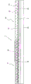
图5是根据本发明的发光阵列的一个实施方式的侧视示意图。Fig. 5 is a schematic side view of an embodiment of a light emitting array according to the present invention.
图6是图5的发光阵列侧视示意图,其中该阵列添加有其他层。Fig. 6 is a schematic side view of the light emitting array of Fig. 5, wherein the array is added with other layers.
图7是根据本发明的用于制造发光阵列的方法的示意图。Fig. 7 is a schematic diagram of a method for manufacturing a light emitting array according to the present invention.
图8是根据本发明的发光阵列的替换实施方式的侧视示意图。Fig. 8 is a schematic side view of an alternative embodiment of a light emitting array according to the present invention.
图9是根据本发明的发光阵列的替换实施方式的侧视示意图。Fig. 9 is a schematic side view of an alternative embodiment of a light emitting array according to the present invention.
具体实施方式Detailed ways
下面将参照附图更全面地描述本发明的实施方式,附图中示出了本发明的实施方式。然而,本发明可以以多种不同的形式体现,并且不应解释为局限于这里阐述的实施方式。相反,提供这些实施方式是为了使本公开全面和完整,并将本发明的范围充分传达给本领域技术人员。相同的标号通篇表示相同的元件。可选元件在图中以虚线示出。Embodiments of the invention will be described more fully hereinafter with reference to the accompanying drawings, in which embodiments of the invention are shown. However, this invention may be embodied in many different forms and should not be construed as limited to the embodiments set forth herein. Rather, these embodiments are provided so that this disclosure will be thorough and complete, and will fully convey the scope of the invention to those skilled in the art. Like reference numerals refer to like elements throughout. Optional elements are shown with dashed lines in the figures.
将理解的是,尽管本文可以使用术语第一、第二等来描述各个元件,但这些元件不应受这些术语的限制。这些术语仅用来将一个元件与另一个元件区分开。例如,第一元件可称为第二元件,并且类似地,第二元件可称为第一元件,而不会背离本发明的范围。如本文所使用的,术语“和/或”包括一个或多个相关所列项目的任意和所有组合。It will be understood that, although the terms first, second etc. may be used herein to describe various elements, these elements should not be limited by these terms. These terms are only used to distinguish one element from another. For example, a first element could be termed a second element, and, similarly, a second element could be termed a first element, without departing from the scope of the present invention. As used herein, the term "and/or" includes any and all combinations of one or more of the associated listed items.
应理解的是,当提及诸如层、区域或基板的元件位于或延伸到另一元件“上”时,其可以直接地位于或延伸到另一元件之上,或者也可以存在中间元件。相反,当提及元件“直接位于另一元件上”或“直接延伸到另一元件上”时,则不存在中间元件。还应理解的是,当提及一个元件“连接至”或“耦接至”另一元件时,其可以直接连接至或耦接至另一元件,或者也可以存在中间元件。相反,当提及元件“直接连接至”或“直接耦接至”另一元件时,则不存在中间元件。It will be understood that when an element such as a layer, region or substrate is referred to as being on or extending "on" another element, it can be directly on or extending on the other element or intervening elements may also be present. In contrast, when an element is referred to as being "directly on" or "directly extending onto" another element, there are no intervening elements present. It will also be understood that when an element is referred to as being "connected" or "coupled" to another element, it can be directly connected or coupled to the other element or intervening elements may also be present. In contrast, when an element is referred to as being "directly connected to" or "directly coupled to" another element, there are no intervening elements present.
本文可以使用相对关系术语,诸如“下方”或“上方”或“上部”或“下部”或“水平”或“竖直”,来描述附图中示出的一个元件、层或区域与另一元件和/或层或区域的关系。将理解的是,这些术语旨在包含器件的除附图中示出的方位之外的不同方位。Relative terms such as "below" or "above" or "upper" or "lower" or "horizontal" or "vertical" may be used herein to describe the relationship between one element, layer or region shown in the figures and another. Relationships between elements and/or layers or regions. It will be understood that these terms are intended to encompass different orientations of the device in addition to the orientation depicted in the figures.
本文所使用的术语只是为了描述具体实施例,而不是旨在限制本发明。如本文所使用的,除非上下文清晰地指示出了其他情况,否则单数形式“一”、“一个”和“该”旨在也包括复数形式。应当进一步理解的是,当术语“包括”、“包含”、“含有”和/或“具有”用在本文中时,表明存在所述的特征、整体、步骤、操作、元件和/或部件,但不排除存在或附加有一个或多个其他的特征、整体、步骤、操作、元件、部件和/或它们的组。The terminology used herein is for the purpose of describing particular embodiments only, and is not intended to limit the invention. As used herein, the singular forms "a", "an" and "the" are intended to include the plural forms as well, unless the context clearly dictates otherwise. It should be further understood that when the terms "comprising", "comprising", "containing" and/or "having" are used herein, it means that the features, integers, steps, operations, elements and/or components exist, But it does not exclude the presence or addition of one or more other features, integers, steps, operations, elements, components and/or their groups.
除非另外定义,否则本文使用的所有术语(包括技术术语和科学术语)与本发明所属领域的普通技术人员通常所理解的具有同样的含义。进一步应当理解的是,本文所使用的术语应当解释为具有与本说明书的上下文中的意思一致的含义,而不应解释为理想的或过于正式的意思,除非本文中清楚地进行了这样的限定。Unless otherwise defined, all terms (including technical and scientific terms) used herein have the same meaning as commonly understood by one of ordinary skill in the art to which this invention belongs. It should be further understood that the terms used herein should be interpreted as having a meaning consistent with the meaning in the context of this specification, and should not be interpreted as an ideal or overly formal meaning, unless such a definition is clearly made herein .
现在参照图5。图5是根据本发明的发光阵列的一个实施方式的侧视示意图。在图5的实施方式中,发光阵列2包括基层4、设置在基层4上的LED6的阵列8、以及覆盖LED阵列8和基层4的光学层10。如所示,光学层10包含发光材料并用从LED阵列8发射的光经过光学层10的方式覆盖LED阵列8。Referring now to FIG. 5 . Fig. 5 is a schematic side view of an embodiment of a light emitting array according to the present invention. In the embodiment of FIG. 5 , the
光学层10可包括一个或多个层,诸如发光层、过滤层、间隔层和/或反射层。在一些实施方式中,光学层10可包括具有一种磷光体或多种磷光体粒子的发光层。在替换实施方式中,光学层10可包括散射粒子,诸如二氧化钛。在另外的实施方式中,光学层10可包括磷光体和散射两者的粒子。在其它实施方式中,阵列2可包括多个光学层10。可在阵列2中的光学层10之间、之中、之上、上方或下方添加另外的层,诸如间隔层和热路径。本领域技术人员将理解的是,额外的电迹线平面可添加到阵列2,以提供与阵列2上的和/或嵌入阵列中的额外电路的电连接。
如图5中所示,LED阵列8的LED6嵌入在发光阵列2内。传统上,LED安装于发光阵列的载体、基板或基台的表面。例如,一个或多个LED可安装于印刷电路板的表面。与此相反,在本发明的发光阵列中,至少一个LED至少部分地嵌入到该阵列自身中,而不是安装于基台的表面。至少部分地嵌入所述至少一个LED到阵列中提供了设计及操作上的优点。例如,LED可以使用内部迹线电连接组成LED阵列。因此,LED相互可以更紧密地布置,因为引线接合对于提供电连接到LED是没有必要的。此外,热管理是有帮助的,因为热量可以遍及整个光学层和基层均匀地散发。光学层可以由导热材料制成,以进一步帮助散热。此外,接地平面可添加到该阵列,以提供散热。接地平面的尺寸可根据散热的需要调整。接地平面构造的示例性材料是铜币。本领域技术人员将理解的是,多种材料可用于作为接地平面。As shown in FIG. 5 , the
阵列2的基层4可由导电性金属材料构成。例如,基层4可以由铝、铁、金或铜(例如,铜箔)构成。基层4的导电性帮助从阵列2散热。基层4可具有大约0.0005英寸到大约0.0010英寸的厚度。例如,基层4的厚度可以为大约0.0007英寸。示例性的基层可以是半盎司铜箔。The
非导电的粘合层或糊剂14可用来将LED6接合至基层4。粘合层14覆盖基层4,从而介于基层4与LED6之间。粘合层14可包括反射材料,以有助于光发射。在替换实施例中,发光阵列2还可包括设置在基层4和粘合层14下面的反射层。在这样的实施例中,粘合层14可以包括光学上透明的粘合剂,诸如硅树脂,以便允许LED6发出的光被反射层反射。反射层可具有多种不同的厚度,并且可包括多种不同的反射材料,合适的材料包括银、金、铝、微孔聚对苯二甲酸乙二醇酯(“MCPET”,微发泡反射板)和漫射光反射器(“DLR”)。本领域技术人员将理解的是,各种材料可用于作为粘合剂胶或糊剂。在另一示例性实施方式中,LED6可具有用于将LED6结合至基层4的焊盘(结合区)。A non-conductive adhesive layer or
在图5中,LED的阵列8结合至基层4。但是,本领域技术人员将理解的是,单个LED6结合至基层4也在本发明的范围内。本领域技术人员还将理解的是,虽然仅示出了LED的一个平面阵列,但LED可位于阵列2的多个平面和/或多个层上以及位于任何期望的电结构中。在LED6上可存在凸块或柱16,用于与粘合层14和基层4连接。如图5所示,LED6简单地放置在基层4上(例如,在基层4中没有形成凹处、开口、孔洞来放置LED6)。In FIG. 5 an
如下面将更详细的解释,LED阵列8中的LED6可以彼此非常紧密地布置在基层4上。LED6的紧密接近是可能的,因为不需要引线接合(在表面安装LED的应用中使用)提供电连接至LED6。相反,LED6可使用内部迹线电连接以组成LED阵列2。因此,LED6可以以靠近邻接的关系布置在基层4上。例如,LED6可以布置成使得在LED6之间存在大约40微米(μm)至大约100微米的间距。在另一个实例中,LED6之间的间距可以在大约40μm至大约80μm之间、大约50μm至大约75μm之间、大约50μm至大约70μm之间、或者大约60μm至大约70μm之间。紧密间距使得能够从相对较小尺寸的LED封装件发射更多的光。本领域技术人员将理解的是,内部迹线可包含任何合适的材料,包括铜。As will be explained in more detail below, the
在图5中,光学层10包含透明材料18和分散在整个透明材料18中的发光材料12。虽然示出了包括透明材料18(其具有分散在整个透明材料18中的发光材料12)的光学层10,但发光阵列2的替换实施方式可包括仅包含透明材料18的光学层10。光学层10可由导热材料构成,以帮助散热。光学层10覆盖LED阵列8和基层4。LED阵列8的LED6可通过光学层10固定在阵列2内。如本文所使用的,“透明材料”可以指具有100%光透射率的材料,但也可以指半透明的材料。可选择透明材料18,以提供不同的绝缘特性。示例性透明材料包括环氧基或硅基材料(例如,环氧树脂或预浸料)。预浸料在本领域中是常用术语,表示“预浸渍”复合纤维。由预浸料构成的复合结构通常需要烘箱或高压釜来固化。示例性预浸渍材料包括FR-4(玻璃织物和环氧树脂)、FR-5(玻璃织物和环氧树脂)、FR-6(哑光玻璃和聚酯)、G-10(玻璃织物和环氧树脂)、CEM-3(玻璃织物和环氧树脂)、CEM-4(玻璃织物和环氧树脂)、和CEM-5(玻璃织物和聚酯)。导热预浸料的示例性制造商和供应商包括Thermagon、Sekisui、台湾Cofan、Bergquist和Denka。其他透明材料对本领域技术人员来说是众所周知的且可获得的。在示例性实施方式中,光学层10包括透明FR-4,其具有分散在整个FR-4材料中的磷光体。其他实施方式可包括光学层10,该光学层包括一个或多个磷光体层。所述一个或多个磷光体层可包括嵌入在阵列2内或形成阵列2中的层的独立介质中的粒子。In FIG. 5 ,
光学层10的厚度可根据嵌入在其中的各器件(诸如LED)的高度而变化。在示例性实施方式中,光学层10可具有大约0.5mm至大约1mm的厚度。例如,光学层10可具有大约0.5mm至大约0.75mm或大约0.6mm至大约0.7mm的厚度。The thickness of the
发光材料12可以分散在光学层10的整个透明材料18内,从而发光材料12不直接涂覆在LED6上作为发光材料层。发光材料12的不直接涂覆帮助阵列2的散热和热管理。透明材料18和发光材料12不形成合成物,而是发光材料12分散在整个透明材料18内。在示例性实施方式中,发光材料12可以均匀地分散在整个透明材料18内。The
发光材料12可以是任何期望的发光材料。本领域技术人员熟悉且已经能够得到各种发光材料。例如,磷光体是一种被激发辐射源激发时发出响应辐射(例如可见光)的发光材料。在很多情况中,响应辐射具有与激发辐射的波长不同的波长。合适的磷光体材料包括但不局限于YAG、TAG、BOSE和CaSrAlSiN3。发光材料的其他实例包括闪烁体、日辉光带和用紫外光照射后在可见光谱中发光的油墨。
发光材料可被归类为向下转换(即,将光子转换到更低能阶(较长的波长)的材料)或向上转换(即,将光子转换到一个更高能阶(较短的波长)的材料)。另外,在示例性实施方式中,光学层10可进一步包括一些已知的添加剂(例如,扩散剂、散射剂、染色剂等)中任何添加剂。Luminescent materials can be classified as down-converting (i.e., materials that convert photons to a lower energy level (longer wavelength)) or up-converting (i.e., materials that convert photons to a higher energy level (shorter wavelength) Material). In addition, in exemplary embodiments, the
如美国专利第7,213,940号中详细说明的(通过引证结合于此),LED和磷光体的结合可用来产生提供可接受的色温、良好的显色指数、以及广域(wide gamut)的高效率白光源。此外,本领域技术人员将可以理解的是,可以选择LED的颜色以及发光材料的颜色和类型,以提供期望的光输出强度和颜色。As detailed in U.S. Patent No. 7,213,940 (incorporated herein by reference), a combination of LEDs and phosphors can be used to produce high-efficiency white LEDs that provide acceptable color temperature, good color rendering index, and wide gamut. light source. Furthermore, those skilled in the art will understand that the color of the LEDs, as well as the color and type of emissive material, can be selected to provide a desired light output intensity and color.
光学层10的表面20可被精加工、粗糙化、图案化、处理,或者在其中形成表面效应(surface effect)22,以帮助获得预定的光输出和改进的光提取。例如,表面图案或被粗糙化的表面区域可以位于光学层10的表面中。尽管在光学层10的表面上来描述这种效应,但效应22也可以添加至阵列2内的位于光学层10的表面之下的其他层。
现在参照图6。图6是图5的发光阵列的侧视示意图,其中该阵列2添加有其他层。如图5中所示,阵列2包括基层4、LED阵列8、粘合层4、以及光学层10。其还包括设置在基层4之下的衬底层24以及接地平面26。在图6中,从顶部到底部,层的顺序包括光学层10、LED阵列8、粘合层14、基层4、衬底层24以及接地平面26。通过提供可具有嵌入于其中的额外部件的层,衬底层24使得能够在发光阵列2中具有更高的整合度(集成度)。例如,包括专用集成电路(ASIC)的所有驱动级电路可嵌入在衬底层24中。在其他实施方式中,LED阵列8自身可至少部分地嵌入在衬底层24中,使得衬底层24与LED阵列8的LED6的至少一个侧部接触。Referring now to FIG. 6 . Fig. 6 is a schematic side view of the light emitting array of Fig. 5, wherein the
衬底层24可包含陶瓷材料、有机绝缘体、环氧树脂或预浸料。在该方面的一个特征中,衬底层24包含预浸料,诸如FR-4、FR-5、FR-6、G-10、CEM-3、CEM-4、和CEM-5。在一些实施方式中,衬底层24和光学层10由相同的材料构成。例如,衬底层24和光学层10两者都可由透明FR-4预浸料构成。技术人员将理解的是,根据阵列的设计目的,其他衬底层也可被包括在阵列中。The
额外的部件嵌入到发光阵列2中进一步减小了LED封装件所需的尺寸。LED封装件整体所占面积的减少对于较小的形状系数(形状因数)的应用特别有利,诸如传统尺寸的灯泡。The embedding of additional components into the
接地平面26可作为热管理工具添加至发光阵列2。可以调整接地平面26的尺寸,以满足发光阵列2的热需求。接地平面26可包括金属箔,诸如铜箔。将认识到的是,尽管在图6中接地平面26与衬底层24接触,但也可预期的是,本发明范围内的LED阵列可具有与基层4接触的接地平面26(例如,在不包括衬底层的实施方式中)。A
微通路(微通孔)28可以形成在基层4中,以将嵌入部件(包括LED6)电连接到电源。例如,通路28可形成在与形成于LED6上的凸块或柱16对应的位置。通路28可通过钻孔(例如,使用激光或机械钻孔)而形成。用于电连接的通路28的存在有利于免去用于为LED6提供电连接的引线接合。因而,通路28使得LED6的间隔更靠近,且因此具有在不牺牲光输出的情况下具有更小LED封装件的能力。尽管图6示出了阵列2内的微通路28的示例性布置,但技术人员将认识和理解的是,可以设计符合本发明教导的其他布置,包括形成在衬底层24中的额外微通路以进一步帮助LED6的电连接和/或提供从LED6的进一步散热。在一些实施方式中,形成在基层4和衬底层24中的微通路28可以以线性结构定位。在其他实施方式中,微通路28可以以非线性结构定位。Micro vias (micro vias) 28 may be formed in the
在示例性实施方式中,发光阵列2是其中嵌入有LED的印刷电路板(PCB)。印刷电路板可以是单面印刷电路板或双面印刷电路板。印刷电路板可包括一个或多个平行层。印刷电路板可包括嵌入该印刷电路板内和/或安装在印刷电路板的外表面上的其他电子器件。电子器件可以单独地封装,诸如电阻器、电容器和晶体管,或者成组地封装,诸如放大器、振荡器和集成电路。在一些实施方式中,所有这些电子器件都嵌入在印刷电路板内。在其他实施方式中,诸如驱动电路、电阻器、电感器和电容器的一些电子器件嵌入在印刷电路板内,而其他电子器件安装在印刷电路板的外表面上。电子器件可以利用表面安装技术(SMT,表面贴装技术)安装在印刷电路板的外表面上。印刷电路板可以在各种不同的应用中使用,包括但不局限于消费类电子产品(即,电视、蜂窝电话、有线电视转换盒等)、专用服务电子产品和高可靠性电子产品。In an exemplary embodiment, the
现在参照图7。图7是根据本发明的发光阵列的一系列侧视示意图,描述了用于制造发光阵列的示例性方法。印刷电路板加工和组装传统上在清洁环境中执行,在清洁环境中可保持空气和部件没有污染。大部分电子器件制造商具有其自己专有的工艺,但下面的方法是可用来制造双面印刷电路板的示例性方法。Referring now to FIG. 7 . 7 is a series of schematic side views of a light emitting array according to the present invention, illustrating an exemplary method for fabricating the light emitting array. Printed circuit board processing and assembly is traditionally performed in clean environments where the air and components are kept free of contamination. Most electronics manufacturers have their own proprietary processes, but the method below is an exemplary method that can be used to manufacture double-sided printed circuit boards.
在该示例性方法中,设置有基层4并且设置有LED6。在图7中,LED6是LED阵列8。例如,基层可以是铜面板。然后可将反射性粘合层涂于铜面板,以形成所谓的背面涂覆粘合剂的铜箔。然后可利用传统方法(例如,射片机)将LED阵列放置在粘合层上。In this exemplary method, a
尽管图7中未示出,但可如下所述地形成光学层10。从卷筒上展开玻璃纤维织物并经过处理站供应,在处理站处,通过浸渍或喷涂用环氧树脂浸渍玻璃纤维织物。对于本发明,这是可以添加发光材料(例如,磷光体)的阶段。然后预浸渍的玻璃纤维可经过滚筒,所述滚筒将材料卷绕至期望的厚度用于精加工后的衬底并且还除去任何多余的树脂。衬底材料经过烘箱,在烘箱中被半固化。在烘箱之后,材料被切成较大的面板。Although not shown in FIG. 7, the
切割后的面板然后可成层地与背面涂覆粘合剂的铜箔交替堆叠。在本发明中,光学层堆叠在LED阵列和基层上(如图7中的中心图所示)。然后将堆叠放置在压力机中,在压力机中,所述堆叠承受大约340°F(170℃)的温度和1500psi的压力一个小时或更长时间。这充分地固化了树脂并将铜箔紧紧地结合在衬底材料的表面上。在示例性实施方式中,光学层可以是其中分散有磷光体的FR-4预浸料。The cut panels can then be stacked in layers alternating with the adhesive-backed copper foil. In the present invention, the optical layer is stacked on the LED array and the base layer (as shown in the center image in Figure 7). The stack is then placed in a press where it is subjected to a temperature of approximately 340°F (170°C) and a pressure of 1500 psi for an hour or more. This fully cures the resin and tightly bonds the copper foil to the surface of the substrate material. In exemplary embodiments, the optical layer may be an FR-4 prepreg having phosphor dispersed therein.
可以使用以下步骤来钻孔或微通路并进行镀敷。衬底或光学层/基层的若干面板(每个都足够大,以制作几个印刷电路板)堆叠在彼此的顶部上,并销连在一起以防止它们移动。将堆叠的面板放置在CNC机器中,并且根据布局电路板时确定的图案来钻孔。然后将这些孔去毛刺,以去除依附于孔边缘的任何多余的材料。将孔的内表面(其设计成提供从电路板的一侧到另一侧的导电电路)用铜镀敷。在从较大的面板上切割各个电路板之后,非导电孔被塞住,以防止它们被镀敷或钻孔。Holes or microvias can be drilled and plated using the following steps. Several panels of the substrate or optical layer/base layer (each large enough to make several printed circuit boards) are stacked on top of each other and pinned together to prevent them from moving. The stacked panels are placed in a CNC machine and the holes are drilled according to the pattern determined when the board was laid out. These holes are then deburred to remove any excess material clinging to the edge of the hole. The inside surface of the hole (which is designed to provide a conductive circuit from one side of the board to the other) is plated with copper. After the individual boards are cut from the larger panel, the non-conductive holes are plugged to prevent them from being plated or drilled.
可以使用以下步骤在光学层/基层合成物上形成印刷电路图案。印刷电路图案可通过“加法”工艺或“减法”工艺形成。在加法工艺中,将铜以期望的图案镀敷或添加到衬底的表面上,留下其余表面不被镀敷。在减法工艺中,首先镀敷衬底的整个表面,然后不是期望图案的部分的区域被蚀刻掉,或被减去。The following steps can be used to form a printed circuit pattern on the optical layer/base layer composition. Printed circuit patterns can be formed by an "additive" process or a "subtractive" process. In an additive process, copper is plated or added to the surface of the substrate in a desired pattern, leaving the remainder of the surface unplated. In a subtractive process, the entire surface of the substrate is first plated, and then the areas that are not part of the desired pattern are etched away, or subtracted.
对于加法工艺,可使用以下步骤。除去衬底或光学层/基层合成物的铜箔表面的油污。面板经过真空腔室,在真空腔室中,将正性光刻胶材料层牢固地压制在铜箔的整个表面上。正性光刻胶材料是具有当暴露于紫外光时变得更可溶的特性的聚合物。真空确保铜箔与光刻胶之间没有气泡。将印刷电路图案掩模放置在光刻胶的顶部上,并将面板暴露于强烈的紫外光中。由于掩模在印刷电路图案的区域中是透明的,所以那些区域中的光刻胶被照射并变得可溶。除去掩模,用碱性显影剂喷涂面板的表面,所述碱性显影剂溶解印刷电路图案的区域中的被照射后的光刻胶,留下暴露于衬底表面上的铜箔。然后用铜对面板进行电镀。衬底表面上的铜箔在这个过程中用作阴极,并且铜在暴露的铜箔区域中被镀敷至大约0.001-0.002英寸(0.025-0.050mm)的厚度。仍覆盖有光刻胶的区域不能用作阴极且不被镀敷。在铜镀层的顶部上镀敷锡-铅或其他保护性涂层,以防止铜被氧化并作为下一制造步骤的抗蚀剂。用溶剂从电路板上剥离光刻胶,以将衬底的铜箔暴露于镀敷的印刷图案之间。用腐蚀掉铜箔的酸性溶液喷涂电路板。印刷电路图案上的铜镀层受锡-铅涂层的保护而不受酸的影响。For additive processes, the following steps can be used. Degreases substrate or copper foil surfaces of optical layer/base layer composites. The panel passes through a vacuum chamber where a layer of positive photoresist material is firmly pressed onto the entire surface of the copper foil. Positive photoresist materials are polymers that have the property of becoming more soluble when exposed to ultraviolet light. The vacuum ensures that there are no air bubbles between the copper foil and the photoresist. A printed circuit pattern mask is placed on top of the photoresist and the panel is exposed to intense UV light. Since the mask is transparent in the areas where the circuit pattern is printed, the photoresist in those areas is illuminated and becomes soluble. The mask is removed and the surface of the panel is sprayed with an alkaline developer that dissolves the irradiated photoresist in the areas of the printed circuit pattern, leaving the copper foil exposed on the surface of the substrate. The panels are then electroplated with copper. The copper foil on the surface of the substrate serves as the cathode in this process, and copper is plated to a thickness of approximately 0.001-0.002 inches (0.025-0.050 mm) in the exposed copper foil areas. Areas still covered with photoresist cannot be used as cathodes and are not plated. A tin-lead or other protective coating is plated on top of the copper plating to protect the copper from oxidation and act as a resist for the next manufacturing step. The photoresist is stripped from the circuit board with a solvent to expose the copper foil of the substrate between the plated printed patterns. Spray the board with an acidic solution that eats away the copper foil. The copper plating on the printed circuit pattern is protected from acid by a tin-lead coating.
另外,光学层10的表面20可被精加工,以获得预定的光输出。表面精加工可包括提供表面图案或在表面的一部分中提供粗糙区域。本领域技术人员将理解的是,在替换实施方式中,阵列2内的其他层可被精加工、粗糙化、图案化、和/或处理,以提供光学层10的表面下的效应。Additionally, the
如果希望有更多的层,其他衬底层可以用上述方式添加至光学层/基层合成物。例如,上述合成物可被翻转,以便将衬底层应用到基层上和/或在基层中钻出微通路从而能够电连接至LED阵列8和其他部件。本领域技术人员将理解如何按照期望来构建各层。可在衬底层24中嵌入其他部件(例如,驱动电路)。也可将接地平面26应用于衬底层24。接地平面26的尺寸是可变的,并且可根据热需求而调整。If more layers are desired, additional substrate layers can be added to the optical layer/base layer composite in the manner described above. For example, the composition described above can be inverted in order to apply a substrate layer to the base layer and/or to drill microvias in the base layer to enable electrical connections to the
现在参照图8。图8是根据本发明的发光阵列30的替换实施方式的侧视示意图。发光阵列30包括基层32、设置在基层32上的LED34的阵列36、以及覆盖LED34的阵列36和基层32的光学层38。粘合层42可涂覆在基层32上,并且LED阵列36可利用传统方法放置在粘合层42上。发光阵列30还包括设置在基层32之下的接地平面50以及第一衬底层52。在该实施方式中,LED阵列36嵌入在第一衬底层52内,使得第一衬底层52与LED阵列36和基层32相邻并接触。在该实施方式中,第一衬底层52可包含透明材料,诸如透明环氧树脂或预浸料。微通路40可形成在基层32中,以将嵌入部件电连接至电源。第二衬底层56设置在基层32之下并与接地平面50接触。Referring now to FIG. 8 . Fig. 8 is a schematic side view of an alternative embodiment of a
光学层38包含其中设置有发光材料46的透明材料44。在一些实施例中,透明材料44可以是透明环氧树脂或预浸料。发光材料46可包括任何合适的材料,包括磷光体。光学层38的表面可被精加工或者其中形成有表面效应48,以帮助获得预定的光输出并漫射光。例如,可在光学层的表面上设置表面图案或粗糙化的表面区域。
如所示,光学层38与嵌入的LED阵列36分离。光学层38可以与嵌入的LED阵列36分离,以便控制发光材料46和LED阵列36产生的热量。例如,在发光材料46是磷光体的实施方式中,磷光体可比LED34产生更多的热量。发光阵列30包括设置在光学层38与嵌入在第一衬底层52内的LED阵列36之间的铜面板54或者迹线。铜面板54可用作扩散在发光阵列30的使用期间由光学层38产生的热量的装置。铜面板54设置在第一衬底层52上方并包括开口55,以允许LED阵列36的LED34发射的光经过第一衬底层52进入光学层38。可经过铜面板54和第一衬底层52至接地平面50钻出热路径58,以帮助散热。如所示,铜面板54的一部分没有被光学层38覆盖。铜面板54的该部分也可用来帮助从光学层38散热。在发光阵列30上设置有与接地平面50接触的其他散热片62、64。散热片62、64可由具有高热导率的材料制成,诸如铝、铜、陶瓷、塑料、合成物或者这些材料的组合。在其他实施方式中,也可以在发光阵列30中包括额外的接地平面,以便更好地帮助散热。As shown, the
第三衬底层60设置在接地平面50之下。通过提供可具有嵌入于其中的额外部件的层,第三衬底层60使得能够在发光阵列30中具有更高的集成度。如所示,部件66(诸如ASIC)嵌入在第三衬底层60中。额外的部件,包括支持器件(诸如电阻器、电感器和电容器),也可嵌入在第三衬底层60内。技术人员将理解的是,根据阵列的设计目的,可在阵列中包括多个接地平面和衬底层。The
现在参照图9。图9是根据本发明的发光阵列70的替换实施方式的侧视示意图。发光阵列70包括基层72、设置在基层72上的LED74的阵列76、以及覆盖LED74的阵列76和基层72的光学层78。粘合层82可涂覆在基层72上,并且LED阵列76可利用传统方法(例如,射片机)放置在粘合层82上。发光阵列70还包括设置在基层72之下的接地平面90。微通路80可形成在基层82中,以将嵌入部件电连接至电源。在发光阵列70上设置有与接地平面90接触的散热片84、86。散热片84、86可由具有高热导率的材料制成,诸如铝、铜、陶瓷、塑料、合成物或者这些材料的组合。Reference is now made to FIG. 9 . FIG. 9 is a schematic side view of an alternative embodiment of a
光学层78包含透明材料79。在一些实施方式中,透明材料79可以是透明环氧树脂或预浸料。如图9所示,发光阵列70可包括设置在光学层78之上可选的透明层81、可选的间隔层83、以及可选的发光层85。虚线表示透明层81、间隔层83以及发光层85的可选特征。如所示,透明层81设置在光学层78之上。在一些实施方式中,透明层81可包含诸如塑料、硅、玻璃、环氧树脂和预浸料的材料。间隔层83设置在透明层81与发光层85之间。间隔层83可包含诸如硅树脂、环氧树脂、油、电介质的透明材料和其他材料。间隔层83可在LED74的阵列76与发光层85之间提供进一步的分离,这可提供额外的散热。发光层85设置在透明层81之上。发光层85可包含透明材料87,该透明材料具有穿过透明材料87设置的发光材料89。合适的发光材料89可包括磷光体、闪烁体、日辉光带和用紫外光照射后在可见光谱中发光的油墨。在一个示例性实施方式中,发光材料89是磷光体。发光层85的表面可被精加工、粗糙化、图案化、处理,或者在其中形成可选的表面效应88(如通过虚线所示),以帮助获得预定的光输出和改进的光提取。例如,表面图案或粗糙化的表面区域可以位于光学层78的表面中。本领域技术人员将理解的是,表面图案或表面区域可设置在发光层85的表面上,或者设置在发光阵列70的位于发光层85之下的分离层中。可经过发光层85、间隔层83和透明层81钻出可选的热路径91(如通过虚线所示),以便允许从发光层85至散热片84、86的散热。本领域技术人员将理解的是,根据阵列70的设计目的,可包括一个或多个可选层。
发光阵列70包括第一衬底层92、第二衬底层94以及第三衬底层96。第一衬底层92、第二衬底层94和第三衬底层96可包含透明材料,诸如透明环氧树脂或预浸料。第一衬底层92设置在基层72之下并与接地平面90接触。第二衬底层94设置在接地平面90下方,并且第三衬底层96设置在第二衬底层94下方。通过提供可具有嵌入于其中的额外部件的层,第一衬底层92、第二衬底层94和第三衬底层96使得能够在发光阵列70中具有更高的集成度。尽管图9所示的实施方式包括第一衬底层92、第二衬底层94和第三衬底层96,但本领域技术人员将理解的是,阵列70可包括更多或更少的衬底层。The
发光阵列70还可包括可选的电子器件93、95和97(如虚线所示)。如所示,电子器件93和95分别嵌入在第一衬底层92和第二衬底层94内。器件93和95可包括驱动级电路(包括ASIC)或者用于操作发光阵列70的其他有源部件。此外,支持器件(诸如电阻器、电感器和电容器)也可嵌入在发光阵列70内。器件97安装在发光阵列70的外表面上。器件97可包括用于操作阵列70的有源器件和无源器件,并且诸如晶体管、振荡器或者额外的LED的部件可安装在发光阵列70的外表面上。器件97可利用表面安装技术安装在发光阵列70的外表面上。技术人员将理解的是,可选的器件93、95和97可设置在发光阵列内的图9所示的所有位置,或者所有的器件设置在发光阵列70内和/或上的一个位置。例如,所有的器件可以嵌入在第一衬底层92内。
在附图和说明书中,公开了本发明的典型实施方式,并且虽然采用了专业术语,但它们仅可在通常的描述意义上使用且不是出于局限的目的,本发明的范围在所附权利要求中阐述。In the drawings and specification, exemplary embodiments of the present invention are disclosed and, although terminology is employed, they are used in a generic, descriptive sense only and not for purposes of limitation, the scope of which is set forth in the appended claims stated in the requirements.
Claims (33)
Applications Claiming Priority (5)
| Application Number | Priority Date | Filing Date | Title |
|---|---|---|---|
| US13/088,693 US9245874B2 (en) | 2011-04-18 | 2011-04-18 | LED array having embedded LED and method therefor |
| US13/088,693 | 2011-04-18 | ||
| US13/417,972 | 2012-03-12 | ||
| US13/417,972 US20130062633A1 (en) | 2011-04-18 | 2012-03-12 | LED Array Having Embedded LED and Method Therefor |
| PCT/US2012/033475 WO2012145237A1 (en) | 2011-04-18 | 2012-04-13 | Led array having embedded led and method therefor |
Publications (1)
| Publication Number | Publication Date |
|---|---|
| CN103608921A true CN103608921A (en) | 2014-02-26 |
Family
ID=46062735
Family Applications (1)
| Application Number | Title | Priority Date | Filing Date |
|---|---|---|---|
| CN201280029852.2A Pending CN103608921A (en) | 2011-04-18 | 2012-04-13 | LED array having embedded LED and method therefor |
Country Status (3)
| Country | Link |
|---|---|
| US (1) | US20130062633A1 (en) |
| CN (1) | CN103608921A (en) |
| WO (1) | WO2012145237A1 (en) |
Cited By (4)
| Publication number | Priority date | Publication date | Assignee | Title |
|---|---|---|---|---|
| CN106098697A (en) * | 2016-06-15 | 2016-11-09 | 深圳市华星光电技术有限公司 | Micro-LED display panel and preparation method thereof |
| CN109841165A (en) * | 2017-11-29 | 2019-06-04 | 利亚德光电股份有限公司 | Small spacing LED display module and preparation method thereof |
| CN109872642A (en) * | 2017-12-04 | 2019-06-11 | 利亚德光电股份有限公司 | Small spacing LED display module and preparation method thereof |
| CN110972414A (en) * | 2018-09-29 | 2020-04-07 | 宏启胜精密电子(秦皇岛)有限公司 | Composite circuit board and method for manufacturing the same |
Families Citing this family (10)
| Publication number | Priority date | Publication date | Assignee | Title |
|---|---|---|---|---|
| US9324692B2 (en) * | 2013-02-18 | 2016-04-26 | Nthdegree Technologies Worldwide Inc. | Transparent LED layer between phosphor layer and light exit surface of lamp |
| US9299887B2 (en) * | 2013-03-15 | 2016-03-29 | Nthdegree Technologies Worldwide Inc. | Ultra-thin printed LED layer removed from substrate |
| US9644829B2 (en) | 2013-04-25 | 2017-05-09 | Xtralight Manufacturing, Ltd. | Systems and methods for providing a field repairable light fixture with a housing that dissipates heat |
| DE102014112673A1 (en) * | 2014-09-03 | 2016-03-03 | Epcos Ag | light emitting diode device |
| US10714460B2 (en) * | 2015-05-29 | 2020-07-14 | Citizen Electronics Co., Ltd. | Light emitting device and manufacturing method thereof |
| DE102016108427A1 (en) * | 2016-05-06 | 2017-11-09 | Epcos Ag | Multi-LED system |
| US20180180795A1 (en) * | 2016-12-22 | 2018-06-28 | Dura Operating, Llc | Light guide and method of creating a light guide by screen-printing |
| CN113540327B (en) * | 2018-05-24 | 2024-07-23 | 大日本印刷株式会社 | Sealing material sheet for self-luminous display or direct-type backlight, self-luminous display, direct-type backlight |
| TWI717670B (en) * | 2018-12-21 | 2021-02-01 | 財團法人工業技術研究院 | Method for inspecting light-emitting diodes and inspection apparatus |
| WO2021002158A1 (en) * | 2019-07-04 | 2021-01-07 | 日亜化学工業株式会社 | Method for manufacturing light emitting device and method for manufacturing light emitting module, and light emitting device and light emitting module |
Citations (4)
| Publication number | Priority date | Publication date | Assignee | Title |
|---|---|---|---|---|
| US20040228107A1 (en) * | 2003-05-12 | 2004-11-18 | Liu-Chung Lee | LED backlight module |
| US20080055863A1 (en) * | 2006-09-05 | 2008-03-06 | Samsung Electro-Mechanics Co., Ltd. | Method of manufacturing as component embedded printed circuit board |
| US20100163892A1 (en) * | 2008-12-29 | 2010-07-01 | Yu-Huan Liu | Led device and method of packaging the same |
| CN201628180U (en) * | 2010-03-19 | 2010-11-10 | 厦门伟然科技有限公司 | Light guide plate with functions of light guiding and scattering |
Family Cites Families (5)
| Publication number | Priority date | Publication date | Assignee | Title |
|---|---|---|---|---|
| EP2596948B1 (en) * | 2003-03-10 | 2020-02-26 | Toyoda Gosei Co., Ltd. | Method of making a semiconductor device |
| US7821023B2 (en) * | 2005-01-10 | 2010-10-26 | Cree, Inc. | Solid state lighting component |
| US7213940B1 (en) | 2005-12-21 | 2007-05-08 | Led Lighting Fixtures, Inc. | Lighting device and lighting method |
| US9159888B2 (en) * | 2007-01-22 | 2015-10-13 | Cree, Inc. | Wafer level phosphor coating method and devices fabricated utilizing method |
| TW201042208A (en) * | 2009-05-27 | 2010-12-01 | Hong Yuan Technology Co Ltd | Lamp system and method for manufacturing multi-chip package of LED |
-
2012
- 2012-03-12 US US13/417,972 patent/US20130062633A1/en not_active Abandoned
- 2012-04-13 WO PCT/US2012/033475 patent/WO2012145237A1/en not_active Ceased
- 2012-04-13 CN CN201280029852.2A patent/CN103608921A/en active Pending
Patent Citations (4)
| Publication number | Priority date | Publication date | Assignee | Title |
|---|---|---|---|---|
| US20040228107A1 (en) * | 2003-05-12 | 2004-11-18 | Liu-Chung Lee | LED backlight module |
| US20080055863A1 (en) * | 2006-09-05 | 2008-03-06 | Samsung Electro-Mechanics Co., Ltd. | Method of manufacturing as component embedded printed circuit board |
| US20100163892A1 (en) * | 2008-12-29 | 2010-07-01 | Yu-Huan Liu | Led device and method of packaging the same |
| CN201628180U (en) * | 2010-03-19 | 2010-11-10 | 厦门伟然科技有限公司 | Light guide plate with functions of light guiding and scattering |
Cited By (7)
| Publication number | Priority date | Publication date | Assignee | Title |
|---|---|---|---|---|
| CN106098697A (en) * | 2016-06-15 | 2016-11-09 | 深圳市华星光电技术有限公司 | Micro-LED display panel and preparation method thereof |
| WO2017215067A1 (en) * | 2016-06-15 | 2017-12-21 | 深圳市华星光电技术有限公司 | Micro light emitting diode display panel and method for manufacturing same |
| CN106098697B (en) * | 2016-06-15 | 2019-04-02 | 深圳市华星光电技术有限公司 | Micro light-emitting diode display panel and manufacturing method thereof |
| CN109841165A (en) * | 2017-11-29 | 2019-06-04 | 利亚德光电股份有限公司 | Small spacing LED display module and preparation method thereof |
| CN109872642A (en) * | 2017-12-04 | 2019-06-11 | 利亚德光电股份有限公司 | Small spacing LED display module and preparation method thereof |
| CN110972414A (en) * | 2018-09-29 | 2020-04-07 | 宏启胜精密电子(秦皇岛)有限公司 | Composite circuit board and method for manufacturing the same |
| CN110972414B (en) * | 2018-09-29 | 2022-09-20 | 宏启胜精密电子(秦皇岛)有限公司 | Composite circuit board and method for manufacturing the same |
Also Published As
| Publication number | Publication date |
|---|---|
| WO2012145237A1 (en) | 2012-10-26 |
| US20130062633A1 (en) | 2013-03-14 |
Similar Documents
| Publication | Publication Date | Title |
|---|---|---|
| CN103608921A (en) | LED array having embedded LED and method therefor | |
| US9245874B2 (en) | LED array having embedded LED and method therefor | |
| KR100955451B1 (en) | Heat radiant fpcb and method for manufacturing the same | |
| JP2008160128A (en) | Printed circuit board, light emitting device including the same, and manufacturing method thereof | |
| US20100149823A1 (en) | Lamp unit, circuit board, and method of manufaturing circuit board | |
| US9728697B2 (en) | Light emitting device including a metal substrate for high heat dissipation and increased light efficiency | |
| CN101604722A (en) | semiconductor light-emitting apparatus | |
| TWM498387U (en) | Thermoelectrically separated LED package module and electrical connection module | |
| CN105980768A (en) | Illuminating film structure | |
| KR20070047676A (en) | LED Mounting Board | |
| KR101498682B1 (en) | Light emitting diode module | |
| KR100853963B1 (en) | High Current Surface Mount LED Lamp Using Circuit Board | |
| CN115989592A (en) | Manufacturing method of phosphor substrate and manufacturing method of light emitting substrate | |
| TW201037803A (en) | Multi-layer packaging substrate, method for making the packaging substrate, and package structure of light-emitting semiconductor | |
| CN104037302A (en) | LED (light-emitting diode) package assembly | |
| KR20080088140A (en) | Heat dissipation substrate and light emitting device including the same | |
| EP3949685A1 (en) | Multi-layer pcb stack for color mixing | |
| JP2006049715A (en) | Luminescent light source, lighting device and display device | |
| KR101457803B1 (en) | Circuit Board For LED | |
| JP2016525792A (en) | Method of manufacturing a printed circuit board assembly based on printed electronic device fabrication technology and printed circuit board assembly | |
| KR100647867B1 (en) | Light emitting device and package structure | |
| KR101278835B1 (en) | Led pcb substrate, pcb, led unit, lighting and its manufacture | |
| CN209964358U (en) | Composite heat dissipation type circuit board and ultraviolet curing module | |
| US20150176819A1 (en) | Metal copper clad laminate and method of manufacturing the same | |
| KR101259854B1 (en) | Circuit board for improved heat dissipation and manufacturing method thereof |
Legal Events
| Date | Code | Title | Description |
|---|---|---|---|
| C06 | Publication | ||
| PB01 | Publication | ||
| C10 | Entry into substantive examination | ||
| SE01 | Entry into force of request for substantive examination | ||
| C02 | Deemed withdrawal of patent application after publication (patent law 2001) | ||
| WD01 | Invention patent application deemed withdrawn after publication |
Application publication date: 20140226 |