CN103561512A - Roadway lighting control method and system with controllable coverage areas - Google Patents
Roadway lighting control method and system with controllable coverage areas Download PDFInfo
- Publication number
- CN103561512A CN103561512A CN201310510307.1A CN201310510307A CN103561512A CN 103561512 A CN103561512 A CN 103561512A CN 201310510307 A CN201310510307 A CN 201310510307A CN 103561512 A CN103561512 A CN 103561512A
- Authority
- CN
- China
- Prior art keywords
- illuminating lamp
- lighting
- brightness
- pedestrian
- control
- Prior art date
- Legal status (The legal status is an assumption and is not a legal conclusion. Google has not performed a legal analysis and makes no representation as to the accuracy of the status listed.)
- Granted
Links
Images


Classifications
-
- Y—GENERAL TAGGING OF NEW TECHNOLOGICAL DEVELOPMENTS; GENERAL TAGGING OF CROSS-SECTIONAL TECHNOLOGIES SPANNING OVER SEVERAL SECTIONS OF THE IPC; TECHNICAL SUBJECTS COVERED BY FORMER USPC CROSS-REFERENCE ART COLLECTIONS [XRACs] AND DIGESTS
- Y02—TECHNOLOGIES OR APPLICATIONS FOR MITIGATION OR ADAPTATION AGAINST CLIMATE CHANGE
- Y02B—CLIMATE CHANGE MITIGATION TECHNOLOGIES RELATED TO BUILDINGS, e.g. HOUSING, HOUSE APPLIANCES OR RELATED END-USER APPLICATIONS
- Y02B20/00—Energy efficient lighting technologies, e.g. halogen lamps or gas discharge lamps
- Y02B20/72—Energy efficient lighting technologies, e.g. halogen lamps or gas discharge lamps in street lighting
Landscapes
- Circuit Arrangement For Electric Light Sources In General (AREA)
Abstract
本发明公开了一种覆盖区域可控的道路照明控制方法及系统,根据道路危险程度、治安状况、天气、环境、车辆及行人的位置、速度等因素对照明灯亮度及照明区域实行动态控制,在事故多发路段、治安较差区域及恶劣天气时进行高亮度、大范围的持续照明,而在普通路段与时段,当车辆及行人经过时,根据其位置、前进方向及速度等因素控制照明灯的照明覆盖区域,仅对车辆及行人前后的部分区域照明,而其他区域则控制照明灯处于预工作状态或熄灭。每个照明灯含多个或多组可独立控制亮度的发光单元,照明灯的照明覆盖区域根据行人及车辆的位置、速度、运动方向等因素通过控制照明灯的每个或每组发光单元的亮度进行调整,本发明通过动态调整亮度降低能耗。
The invention discloses a road lighting control method and system with controllable coverage area, which dynamically controls the brightness of the lighting lamp and the lighting area according to factors such as road danger, public security situation, weather, environment, position and speed of vehicles and pedestrians. Accident-prone road sections, areas with poor public security and bad weather provide high-brightness, large-scale continuous lighting. In ordinary road sections and time periods, when vehicles and pedestrians pass by, the lights are controlled according to their position, direction of travel, and speed. The lighting coverage area only illuminates the part of the area in front of and behind vehicles and pedestrians, while other areas control the lights to be in the pre-working state or extinguished. Each lighting lamp contains multiple or multiple groups of light-emitting units that can independently control the brightness. The lighting coverage area of the lighting lamp is controlled by each or each group of lighting units of the lighting lamp according to the position, speed, and direction of movement of pedestrians and vehicles. The brightness is adjusted, and the present invention reduces energy consumption by dynamically adjusting the brightness.
Description
技术领域 technical field
本发明涉及照明控制方法,更具体涉及一种覆盖区域可控的道路照明控制方法及系统。 The present invention relates to a lighting control method, and more particularly to a road lighting control method and system with controllable coverage area.
背景技术 Background technique
道路照明主要作用是提高交通系统的安全性,为行人及驾驶人员提供清晰的视线来减少交通事故,然而道路照明需要消耗大量的能源,增加大量的成本,同时随着夜晚通行车辆及行人的减少使得大量的能源被浪费,并给环境带来光污染。当前对道路照明的处理普遍是将所有照明灯的亮度降低或熄灭,虽然可以降低能耗但会导致安全性降低。 The main function of road lighting is to improve the safety of the traffic system, provide pedestrians and drivers with a clear line of sight to reduce traffic accidents, however, road lighting needs to consume a lot of energy and increase a lot of costs, and at the same time, with the reduction of vehicles and pedestrians at night A large amount of energy is wasted and light pollution is brought to the environment. The current treatment of road lighting is generally to reduce or extinguish the brightness of all lighting lamps. Although energy consumption can be reduced, safety will be reduced.
发明内容 Contents of the invention
鉴于上述现有技术的现状和存在的问题,本发明的目的在于,为通行车辆及行人的道路照明提供一种覆盖区域可控的道路照明控制方法及系统。 In view of the current situation and existing problems of the above-mentioned prior art, the object of the present invention is to provide a road lighting control method and system with controllable coverage area for road lighting of passing vehicles and pedestrians.
本发明的目的通过如下技术方案实现: The purpose of the present invention is achieved through the following technical solutions:
一种覆盖区域可控的道路照明控制方法,该控制方法中,道路采用多个照明灯进行照明,每个照明灯的控制单元根据道路危险程度、治安状况、天气、环境、车辆及行人的位置、速度因素对照明灯的亮度及覆盖区域实行动态控制,对危险路段、社会治安较差的关键区域以及遇到恶劣天气时的路段进行较高亮度大范围的持续照明,而对于普通路段与时段,当车辆及行人经过时,根据车辆及行人的位置、前进方向及速度因素控制照明灯的照明覆盖区域,仅对车辆及行人所在位置及前后设定范围内的安全区域进行照明,而安全区域以外的照明灯仅维持其预工作状态或熄灭。 A road lighting control method with controllable coverage area. In the control method, the road is illuminated by multiple lighting lamps. , speed factor to implement dynamic control on the brightness and coverage area of the lighting, and carry out continuous lighting with high brightness and large range for dangerous road sections, key areas with poor social security and road sections in bad weather, while for ordinary road sections and time periods, When vehicles and pedestrians pass by, the lighting coverage area of the lights is controlled according to the position, direction and speed of the vehicles and pedestrians, and only the safe area within the position of the vehicle and pedestrians and the set range before and after is illuminated, while outside the safe area The lighting lamps only maintain their pre-operational status or go out.
实现上述一种覆盖区域可控的道路照明控制方法的控制系统系统,其包括多个照明灯,每个照明灯包括一个控制单元和多个可独立控制亮度的发光单元,所述控制单元包括传感模块、信号处理模块、亮度控制模块和网络通信模块;所述传感模块用于对车辆及行人速度、位置、行进方向和天气进行检测,并通过电压电流参数传感器及亮度传感器对照明灯的状态及亮度进行测量以监测照明灯是否存在故障,传感模块所测信息被送到信号处理模块;信号处理模块接收所测信息及相邻照明灯通过网络通信模块传输过来的行人及车辆位置及运动方向信息后,根据车辆及行人的运动速度、天气状况控制亮度控制模块以改变本照明灯各发光单元的电压、电流参数,控制各发光单元的亮度,进而调整本照明灯照明覆盖区域,同时根据传感模块对照明灯的电压、电流参数及照明灯亮度的测量,监测照明灯自身的状态,如果存在电压、电流及亮度异常,则通过网络通信模块发送照明灯当前的电压、电流、亮度参数到照明灯控制中心或道路照明管理维护部门,便于更换故障部件或照明灯及时排除故障;网络通信模块通过有线或无线的方式接收相邻照明灯的控制单元传入的行人、车辆位置和运动方向及相邻照明灯电压、电流及亮度等状态信息以及将本照明灯控制单元测量的行人、车辆位置和运动方向及本照明灯电压、电流及亮度等状态信息发送到相邻照明灯的控制单元,实现数据的发送与接收。 The control system for realizing the above-mentioned road lighting control method with controllable coverage area includes a plurality of lighting lamps, each lighting lamp includes a control unit and a plurality of light-emitting units that can independently control the brightness, and the control unit includes a transmission sensor module, signal processing module, brightness control module and network communication module; the sensor module is used to detect the speed, position, direction of travel and weather of vehicles and pedestrians, and monitor the status of lighting lamps through voltage and current parameter sensors and brightness sensors and brightness are measured to monitor whether there is a fault in the lighting lamp, and the information measured by the sensing module is sent to the signal processing module; the signal processing module receives the measured information and the position and movement of pedestrians and vehicles transmitted by the adjacent lighting lamp through the network communication module After receiving the direction information, control the brightness control module according to the movement speed of vehicles and pedestrians and weather conditions to change the voltage and current parameters of each light-emitting unit of the lighting lamp, control the brightness of each light-emitting unit, and then adjust the lighting coverage area of the lighting lamp. The sensor module measures the voltage and current parameters of the lighting lamp and the brightness of the lighting lamp, and monitors the status of the lighting lamp itself. If there is an abnormal voltage, current and brightness, the current voltage, current and brightness parameters of the lighting lamp are sent to the network communication module. The lighting control center or road lighting management and maintenance department facilitates the replacement of faulty parts or timely troubleshooting of lighting; the network communication module receives the pedestrian, vehicle position and movement direction from the control unit of the adjacent lighting through wired or wireless means and State information such as the voltage, current, and brightness of adjacent lighting lamps, as well as status information such as the position and direction of movement of pedestrians and vehicles measured by the control unit of this lighting lamp, and the status information such as voltage, current, and brightness of this lighting lamp are sent to the control unit of the adjacent lighting lamp, Realize the sending and receiving of data. the
进一步地,所述传感模块包括行人及车辆位置的传感器、照明灯供电的电压电流传感器、照明灯照明亮度传感器,信号调理电路,和模数转换电路;行人及车辆位置的传感器用于检测行人及车辆的位置及行进方向;信号调理电路用于对各传感器输出的检测信号进行放大、滤波;模数转换电路用于对信号调理电路输出的信号进行模数转换,将模拟信号转换为数字信号。 Further, the sensing module includes sensors for the position of pedestrians and vehicles, voltage and current sensors powered by lighting lamps, lighting brightness sensors for lighting lamps, signal conditioning circuits, and analog-to-digital conversion circuits; the sensors for pedestrians and vehicles are used to detect pedestrians and the position and direction of travel of the vehicle; the signal conditioning circuit is used to amplify and filter the detection signals output by each sensor; the analog-to-digital conversion circuit is used to perform analog-to-digital conversion on the signal output by the signal conditioning circuit, and convert the analog signal into a digital signal . the
进一步地,所述信号处理模块包括数字信号处理芯片和储存芯片,用于对传感模块输出的数字信号、网络通信模块接收的数据进行分析,信号处理模块内部存储覆盖行人及车辆位置的照明区域所对应的发光单元数据库,根据数据库确定本照明灯的各发光单元的亮度,并通过亮度控制模块控制各发光单元的亮度,如果超出本照明灯的照明覆盖区域需要相邻照明灯进行照明覆盖,则通过网络通信模块发送信息到相邻照明灯,由相邻照明灯所对应的发光单元照明。 Further, the signal processing module includes a digital signal processing chip and a storage chip, which are used to analyze the digital signal output by the sensor module and the data received by the network communication module, and the signal processing module internally stores the lighting area covering the position of pedestrians and vehicles The corresponding light-emitting unit database determines the brightness of each light-emitting unit of the lighting according to the database, and controls the brightness of each light-emitting unit through the brightness control module. Then, the information is sent to the adjacent lighting lamp through the network communication module, and the light emitting unit corresponding to the adjacent lighting lamp is illuminated. the
进一步地,所述亮度控制模块包括照明灯各发光单元的用于电压、电流控制的电源驱动芯片,亮度控制模块接收信号处理模块的控制命令,控制各发光单元的电压及电流,进而调整各发光单元的亮度。 Further, the brightness control module includes a power drive chip for voltage and current control of each light-emitting unit of the lighting lamp. The brightness control module receives a control command from the signal processing module to control the voltage and current of each light-emitting unit, and then adjusts each light-emitting unit. The brightness of the unit.
进一步地,每个照明灯的多个或多组发光单元布置于照明灯的平面形状支撑体上,或者将多个发光单元布置于圆柱形或球面形状的支撑体上,利用支撑体的形状及发光单元的光线照射角改变照明覆盖区域。 Further, multiple or multiple groups of light-emitting units of each lighting lamp are arranged on the planar support of the lighting lamp, or a plurality of light-emitting units are arranged on a cylindrical or spherical support, using the shape of the support and The light irradiation angle of the light emitting unit changes the illumination coverage area. the
利用上述控制系统的道路照明控制方法,其具体包括如下步骤: The road lighting control method using the above control system specifically includes the following steps:
7.1 每个照明灯的网络通信模块接收相邻照明灯的网络通信模块发送的行人及车辆位置及运动方向信息,传感模块检测本照明灯照明覆盖区域内行人及车辆位置及行进方向; 7.1 The network communication module of each lighting lamp receives the pedestrian and vehicle position and movement direction information sent by the network communication module of the adjacent lighting lamp, and the sensing module detects the position and direction of travel of pedestrians and vehicles within the lighting coverage area of the lighting lamp;
7.2当一个照明灯接收到相邻照明灯发送的行人及车辆的位置和行进方向及相邻照明灯的电压、电流及亮度状态信息及本照明灯的传感模块检测到的行人及车辆位置信息后通知本照明灯的信号处理模块,信号处理模块根据行人及车辆的位置及前进方向信息,查询信号处理模块中存储器内的数据库,得到本照明灯各发光单元对应的亮度信息,并通知亮度控制模块; 7.2 When a lighting lamp receives the position and direction of travel of pedestrians and vehicles sent by adjacent lighting lamps, the voltage, current and brightness status information of adjacent lighting lamps, and the position information of pedestrians and vehicles detected by the sensing module of this lighting lamp Then notify the signal processing module of this lighting lamp, the signal processing module queries the database in the memory of the signal processing module according to the position and direction information of pedestrians and vehicles, obtains the brightness information corresponding to each light-emitting unit of this lighting lamp, and notifies the brightness control module;
7.3 亮度控制模块根据信号处理模块发送的各发光单元对应的亮度信息,控制本照明灯各发光单元的电压、电流,进而调整各发光单元的亮度; 7.3 The brightness control module controls the voltage and current of each light-emitting unit of the light according to the brightness information corresponding to each light-emitting unit sent by the signal processing module, and then adjusts the brightness of each light-emitting unit;
7.4 传感模块检测照明灯的亮度及电压、电流参数,判断是否存在异常,如果存在异常则通过网络通信模块通知照明灯控制中心及道路照明管理维护部门对照明灯维修更换故障部件。 7.4 The sensing module detects the brightness, voltage and current parameters of the lighting lamp, and judges whether there is an abnormality. If there is an abnormality, the lighting control center and the road lighting management and maintenance department are notified through the network communication module to repair and replace the faulty parts of the lighting lamp.
上述控制方法中,每个照明灯照明覆盖区域长度为L,由传感模块检测照明灯照明覆盖区域内的车辆及行人的位置及行进方向,根据行人及车辆的位置对行人及车辆后方长度为a、前方长度为b的区域照明,当行人及车辆前进至本照明灯覆盖区域边缘超出本照明灯的照明覆盖区域时,由行进方向前方与照明灯相邻的照明灯对行人及车辆进行照明,以保证行人及车辆后方长度为a、前方长度为b的区域(a+b)得到照明灯的照明,当行人及车辆行进至后方长度为a、前方长度为b的区域全部超出本照明灯的照明覆盖区域后,由行进方向前方与本照明灯相邻的照明灯对行人及车辆后方长度为a、前方长度为b的区域进行照明,直至超出照明覆盖区域后由下一个相邻的照明灯进行照明。 In the above control method, the length of the lighting coverage area of each lighting lamp is L, and the position and direction of travel of the vehicles and pedestrians in the lighting coverage area of the lighting lamp are detected by the sensing module, and the rear length of pedestrians and vehicles is a. The area with the length b in front is illuminated. When pedestrians and vehicles advance to the edge of the area covered by this light beyond the area covered by this light, the pedestrians and vehicles will be illuminated by the light adjacent to the light in front of the direction of travel. , so as to ensure that the area (a+b) with length a behind and b in front of pedestrians and vehicles is illuminated by the lighting lamp. After the lighting coverage area, the area with the length a behind and the length b in front of pedestrians and vehicles will be illuminated by the lighting lamp adjacent to this lighting lamp in front of the direction of travel, until the next adjacent lighting lamp is used after exceeding the lighting coverage area. Lamp for lighting.
与现有技术相比,本发明具有如下优点和技术效果: Compared with the prior art, the present invention has the following advantages and technical effects:
本发明能根据道路危险程度、治安状况、天气、环境、车辆及行人的位置、速度等因素对照明灯亮度及照明区域实行动态控制,在事故多发路段、治安较差区域及恶劣天气时进行高亮度、大范围的持续照明,而在普通路段与时段,当车辆及行人经过时,根据其位置、前进方向及速度等因素控制照明灯的照明覆盖区域,仅对车辆及行人前后的部分区域照明,而其他区域则控制照明灯处于预工作状态或熄灭。本发明在实现降低能源消耗的情况下,不降低道路通行的安全性,照明灯出现异常时,还能通过网络通信模块通知照明灯控制中心及道路照明管理维护部门对照明灯维修更换故障部。 The invention can dynamically control the brightness of the lighting lamp and the lighting area according to factors such as road danger, public security situation, weather, environment, position and speed of vehicles and pedestrians, and perform high-brightness control on accident-prone road sections, poor public security areas and bad weather. , Large-scale continuous lighting, while in ordinary road sections and time periods, when vehicles and pedestrians pass by, the lighting coverage area of the lights is controlled according to factors such as their position, forward direction and speed, and only the partial areas in front of and behind vehicles and pedestrians are illuminated. In other areas, the control lights are in the pre-working state or extinguished. In the case of reducing energy consumption, the present invention does not reduce the safety of road traffic, and when the lighting lamp is abnormal, it can also notify the lighting lamp control center and the road lighting management and maintenance department to repair and replace the faulty part of the lighting lamp through the network communication module.
附图说明 Description of drawings
图1为控制系统组成结构图。 Figure 1 is a structural diagram of the control system.
图2为传感模块,主要由传感器、放大滤波电路及模数转换电路组成。 Figure 2 shows the sensing module, which is mainly composed of sensors, amplification and filtering circuits, and analog-to-digital conversion circuits.
图3为信号处理模块,主要包括CPU及位置对应的发光单元亮度数据库。 FIG. 3 is a signal processing module, which mainly includes a CPU and a brightness database of light-emitting units corresponding to positions.
图4为亮度控制模块,主要包括电压、电流控制的电源驱动芯片组成。 Figure 4 shows the brightness control module, which mainly includes voltage and current control power drive chips.
图5为照明灯内各发光单元的排列分别图。 Fig. 5 is a diagram showing the arrangement of each light-emitting unit in the illuminating lamp.
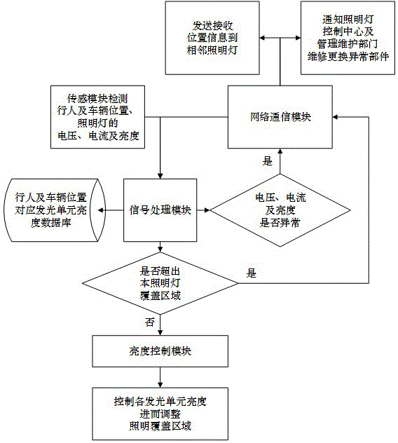
图6为照明覆盖区域控制流程图。 Fig. 6 is a flow chart of lighting coverage area control.
图7为照明覆盖区域控制示意图,图中虚线为照明灯的最大覆盖区域,填充部分为照明灯根据行人及车辆运动方向及位置调整的可调覆盖区域。 Figure 7 is a schematic diagram of lighting coverage area control. The dotted line in the figure is the maximum coverage area of the lighting lamp, and the filled part is the adjustable coverage area of the lighting lamp according to the movement direction and position of pedestrians and vehicles.
the
具体实施方式 Detailed ways
以下结合附图对本发明的实施作进一步说明,但本发明的实施和保护不限于此。 The implementation of the present invention will be further described below in conjunction with the accompanying drawings, but the implementation and protection of the present invention are not limited thereto.
本发明的道路照明控制系统的照明灯包含多个或多组可独立控制亮度的发光单元,如图1,每个照明灯的控制单元包括传感模块1、信号处理模块2、亮度控制模块3、网络通信模块4;传感模块1用于对车辆及行人速度、位置、行进方向、天气状况(如是否存在风雨)进行测量,并对照明灯亮度进行测量,所测信息被送到信号处理模块2,信号处理模块2接收所测信息及其他组通过网络通信模块4传输的信息进行处理后控制亮度控制模块3调整本照明灯照明覆盖区域,同时根据对照明灯亮度的测量监测照明灯自身的状态,并通过网络通信模块4发送到相邻照明灯及照明灯控制中心进行必要的维护,网络通信模块4通过有线或无线的方式接收其他照明灯传入的信息以及将本组测量信息发送到其他照明灯控制单元,实现数据的发送与接收。 The lighting lamp of the road lighting control system of the present invention includes multiple or multiple groups of light-emitting units that can independently control brightness, as shown in Figure 1, the control unit of each lighting lamp includes a sensing module 1, a signal processing module 2, and a brightness control module 3 , Network communication module 4; Sensing module 1 is used to measure the speed, position, direction of travel, weather conditions (such as whether there is wind and rain) of vehicles and pedestrians, and measure the brightness of lighting lamps, and the measured information is sent to the signal processing module 2. The signal processing module 2 receives the measured information and other groups of information transmitted through the network communication module 4 to process and then control the brightness control module 3 to adjust the lighting coverage area of the lighting lamp, and at the same time monitor the status of the lighting lamp itself according to the measurement of the brightness of the lighting lamp , and through the network communication module 4 to send to adjacent lights and light control center for necessary maintenance, the network communication module 4 receives the incoming information from other lights and sends this group of measurement information to other lights through wired or wireless The lighting control unit realizes the sending and receiving of data.
每个照明灯包括一个控制单元和多个或多组可独立控制亮度的发光单元,发光单元排列在照明灯的平面形状支撑体上,或者为了提高照明灯的覆盖面积,将发光单元布置于圆柱形或球面形状的支撑体上,利用支撑体的形状及发光单元的光线照射角改变照明覆盖区域。每个照明灯的多个或多组发光单元布置于照明灯的平面形状支撑体上,或者为了提高照明灯的覆盖面积,将发光单元布置于圆柱形或球面形状的支撑体上,利用支撑体的形状及发光单元的光线照射角改变照明覆盖区域。 Each light includes a control unit and multiple or multiple sets of light-emitting units that can independently control the brightness. The light-emitting units are arranged on the planar support of the light, or in order to increase the coverage area of the light, the light-emitting units are arranged on a cylinder On a support body with a spherical or spherical shape, the illumination coverage area can be changed by using the shape of the support body and the light irradiation angle of the light-emitting unit. Multiple or multiple groups of light-emitting units of each lighting lamp are arranged on the planar shape support of the lighting lamp, or in order to increase the coverage area of the lighting lamp, the light-emitting units are arranged on a cylindrical or spherical support, and the support body The shape of the light-emitting unit and the light irradiation angle of the light-emitting unit change the illumination coverage area.
传感模块用于对车辆及行人速度、位置、行进方向、天气等进行测量,并通过照明灯的电压、电流等电气参数及亮度传感器对照明灯的状态及亮度进行测量以监测照明灯是否存在故障。如图3,传感模块包括行人及车辆位置的传感器、照明灯供电的电压、电流传感器、照明灯照明亮度传感器,各传感器信号放大、滤波的信号调理电路,模数转换电路等。位置的传感可通过超声波、红外线、电感线圈、光电传感器等实现,用于检测行人及车辆的位置及行进方向;信号调理电路用于对传感器输出的检测信号进行放大、滤波,以满足模数转换的要求;模数转换电路用于对信号调理电路输出的信号进行模数转换,将模拟信号转换为数字信号,以进行后续的数字信号处理。 The sensing module is used to measure the speed, position, direction of travel, weather, etc. of vehicles and pedestrians, and measure the status and brightness of the lighting lamp through the voltage, current and other electrical parameters of the lighting lamp and the brightness sensor to monitor whether the lighting lamp is faulty . As shown in Figure 3, the sensing module includes sensors for pedestrians and vehicles, voltage and current sensors for power supply of lighting lamps, lighting brightness sensors for lighting lamps, signal conditioning circuits for signal amplification and filtering of each sensor, analog-to-digital conversion circuits, etc. The position sensing can be realized by ultrasonic, infrared, inductive coil, photoelectric sensor, etc., which are used to detect the position and direction of travel of pedestrians and vehicles; the signal conditioning circuit is used to amplify and filter the detection signal output by the sensor to meet the modulus Conversion requirements; the analog-to-digital conversion circuit is used to perform analog-to-digital conversion on the signal output by the signal conditioning circuit, and convert the analog signal into a digital signal for subsequent digital signal processing.
信号处理模块接收所测信息及相邻照明灯通过网络通信模块传输过来的信息后,根据车辆及行人的运动速度控制亮度控制模块改变本照明灯各发光单元的电压、电流等电气参数,控制各发光单元的亮度,进而调整本照明灯照明覆盖区域,同时根据对照明灯的电压、电流等电气参数测量及亮度传感器对照明灯亮度的测量,监测照明灯自身的状态,如存在电压、电流及亮度等的异常则通过网络通信模块发送照明灯当前电压、电流、亮度等参数到相邻照明灯控制单元及照明灯控制中心及道路照明管理维护部门,更换故障部件或照明灯及时排除故障。如图2,信号处理模块包括CPU、MCU、DSP或FPGA等数字信号处理芯片和储存芯片等,用于对传感模块输出的数字信号、网络通信模块接收的数据进行分析,信号处理模块内部存储覆盖行人及车辆位置的照明区域所对应的发光单元数据库,根据数据库确定本照明灯的各发光单元的亮度,并通过亮度控制模块控制各发光单元的亮度,如果超出本照明灯的照明覆盖区域需要相邻照明灯进行照明覆盖,则通过网络通信模块发送信息到相邻照明灯,由相邻照明灯所对应的发光单元照明。 After the signal processing module receives the measured information and the information transmitted by the adjacent lighting lamps through the network communication module, it controls the brightness according to the movement speed of vehicles and pedestrians. The brightness of the light-emitting unit, and then adjust the lighting coverage area of the lighting. At the same time, according to the measurement of electrical parameters such as the voltage and current of the lighting and the measurement of the brightness of the lighting by the brightness sensor, monitor the status of the lighting itself, such as the presence of voltage, current and brightness. If there is an abnormality, the current voltage, current, brightness and other parameters of the lighting lamp are sent to the adjacent lighting control unit, lighting control center and road lighting management and maintenance department through the network communication module, and the faulty parts or lighting lamps are replaced in time to troubleshoot. As shown in Figure 2, the signal processing module includes digital signal processing chips such as CPU, MCU, DSP or FPGA and storage chips, etc., which are used to analyze the digital signal output by the sensor module and the data received by the network communication module, and the internal storage of the signal processing module The luminous unit database corresponding to the lighting area covering the position of pedestrians and vehicles, determine the brightness of each luminous unit of this lighting according to the database, and control the brightness of each luminous unit through the brightness control module, if it exceeds the lighting coverage area of this lighting. When the adjacent lighting lamps perform lighting coverage, the information is sent to the adjacent lighting lamps through the network communication module, and the light-emitting units corresponding to the adjacent lighting lamps are illuminated.
如图4,亮度控制模块对发光单元进行电源管理,亮度控制模块包括照明灯各发光单元的用于电压、电流控制的电源驱动芯片,亮度控制模块接收信号处理模块的控制命令,控制各发光单元的电压及电流,进而调整各发光单元的亮度。 As shown in Figure 4, the brightness control module manages the power supply of the light-emitting units. The brightness control module includes power drive chips for voltage and current control of each light-emitting unit of the lighting lamp. The brightness control module receives control commands from the signal processing module and controls each light-emitting unit. voltage and current, and then adjust the brightness of each light-emitting unit.
网络通信模块通过有线或无线的方式接收其他照明灯控制单元传入的信息以及将本照明灯控制单元的测量信息发送到其他照明灯的控制单元,实现数据的发送与接收。 The network communication module receives information from other lighting control units and sends the measurement information of this lighting control unit to other lighting control units through wired or wireless, so as to realize data transmission and reception.
如图5,每个照明灯的多个或多组发光单元布置于照明灯的平面形状支撑体上。为了提高照明灯的覆盖面积,还能将多个发光单元布置于圆柱形或球面形状的支撑体上,利用支撑体的形状及发光单元的光线照射角改变照明覆盖区域。 As shown in FIG. 5 , multiple or multiple groups of light emitting units of each lighting lamp are arranged on the planar support body of the lighting lamp. In order to increase the coverage area of the lighting lamp, a plurality of light-emitting units can also be arranged on a cylindrical or spherical support body, and the illumination coverage area can be changed by using the shape of the support body and the light irradiation angle of the light-emitting unit.
本实例的照明覆盖区域控制流程如图6所示: The lighting coverage area control process of this example is shown in Figure 6:
1 网络通信模块接收相邻照明灯网络通信模块发送的行人及车辆位置及运动方向信息,传感模块检测本照明灯照明覆盖区域内行人及车辆位置及行进方向; 1 The network communication module receives the position and direction information of pedestrians and vehicles sent by the network communication module of adjacent lights, and the sensing module detects the position and direction of travel of pedestrians and vehicles in the lighting coverage area of this light;
2当一个照明灯接收到相邻照明灯发送的行人及车辆的位置和行进方向及相邻照明灯的电压、电流及亮度状态信息及本照明灯的传感模块检测到的行人及车辆位置信息后通知本照明灯的信号处理模块,信号处理模块根据行人及车辆的位置及前进方向信息,查询信号处理模块中存储器内的数据库,得到本照明灯各发光单元对应的亮度信息(如亮与不亮),并通知亮度控制模块; 2 When a lighting lamp receives the position and direction of travel of pedestrians and vehicles sent by adjacent lighting lamps, the voltage, current and brightness status information of adjacent lighting lamps, and the position information of pedestrians and vehicles detected by the sensing module of this lighting lamp Then notify the signal processing module of the lighting lamp, the signal processing module queries the database in the memory of the signal processing module according to the position and direction information of pedestrians and vehicles, and obtains the brightness information corresponding to each light-emitting unit of the lighting lamp (such as whether it is bright or not). bright), and notify the brightness control module;
3亮度控制模块根据信号处理模块发送的各发光单元对应的亮度信息(如亮与不亮),控制本照明灯各发光单元的电压、电流,进而调整各发光单元的亮度;; 3 The brightness control module controls the voltage and current of each light-emitting unit of the lighting lamp according to the brightness information (such as on and off) corresponding to each light-emitting unit sent by the signal processing module, and then adjusts the brightness of each light-emitting unit;
4 传感模块检测照明灯的亮度及电压、电流等电气参数,判断是否存在异常,如果存在异常则通过网络通信模块通知照明灯控制中心及道路照明管理维护部门对照明灯维修更换故障部件。 4 The sensing module detects the brightness, voltage, current and other electrical parameters of the lighting lamp to determine whether there is an abnormality. If there is an abnormality, the lighting control center and the road lighting management and maintenance department are notified through the network communication module to repair and replace the faulty parts of the lighting lamp.
照明覆盖区域控制的过程如图7所示:照明灯照明覆盖区域长度为L,由传感模块检测照明灯照明覆盖区域内的车辆及行人的位置及行进方向,根据行人及车辆的位置对其后方长度为a、前方长度为b的区域照明,L=a+b;当行人及车辆前进至本照明灯覆盖区域边缘超出本照明灯的照明覆盖区域时,由行进方向前方与照明灯相邻的照明灯对行人及车辆进行照明,以保证行人及车辆后方长度为a、前方长度为b的区域(a+b)得到照明灯的照明,当行人及车辆行进至后方长度为a、前方长度为b的区域全部超出本照明灯的照明覆盖区域后,由行进方向前方与本照明灯相邻的照明灯对行人及车辆后方长度为a、前方长度为b的区域进行照明,直至超出照明覆盖区域后由下一个相邻的照明灯进行照明。 The process of lighting coverage area control is shown in Figure 7: the length of the lighting coverage area is L, and the sensor module detects the position and direction of travel of vehicles and pedestrians in the lighting coverage area, and adjusts them according to the positions of pedestrians and vehicles. The area with the rear length a and the front length b is illuminated, L=a+b; when pedestrians and vehicles advance to the edge of the area covered by the light beyond the area covered by the light, they will be adjacent to the light from the front in the direction of travel The lights of pedestrians and vehicles are illuminated to ensure that the area (a+b) with a length behind the pedestrians and vehicles and a length b in front is illuminated by the lights. After all the areas of b exceed the lighting coverage area of this lighting lamp, the lighting lamps adjacent to this lighting lamp in front of the direction of travel will illuminate the area with length a behind and b in front of pedestrians and vehicles until the lighting coverage is exceeded The area is then illuminated by the next adjacent light.
Claims (8)
Priority Applications (1)
| Application Number | Priority Date | Filing Date | Title |
|---|---|---|---|
| CN201310510307.1A CN103561512B (en) | 2013-10-25 | 2013-10-25 | The road lighting control method that a kind of overlay area is controlled and system |
Applications Claiming Priority (1)
| Application Number | Priority Date | Filing Date | Title |
|---|---|---|---|
| CN201310510307.1A CN103561512B (en) | 2013-10-25 | 2013-10-25 | The road lighting control method that a kind of overlay area is controlled and system |
Publications (2)
| Publication Number | Publication Date |
|---|---|
| CN103561512A true CN103561512A (en) | 2014-02-05 |
| CN103561512B CN103561512B (en) | 2015-09-02 |
Family
ID=50015613
Family Applications (1)
| Application Number | Title | Priority Date | Filing Date |
|---|---|---|---|
| CN201310510307.1A Expired - Fee Related CN103561512B (en) | 2013-10-25 | 2013-10-25 | The road lighting control method that a kind of overlay area is controlled and system |
Country Status (1)
| Country | Link |
|---|---|
| CN (1) | CN103561512B (en) |
Cited By (15)
| Publication number | Priority date | Publication date | Assignee | Title |
|---|---|---|---|---|
| CN105530747A (en) * | 2016-01-21 | 2016-04-27 | 青岛海尔智能家电科技有限公司 | A street lamp control method and device |
| CN106465515A (en) * | 2014-06-26 | 2017-02-22 | 飞利浦灯具控股公司 | Automatically commissioning a group of lighting units |
| CN107172749A (en) * | 2017-06-09 | 2017-09-15 | 四川力天世纪科技有限公司 | The intelligence control system of effectively save corridor electricity consumption |
| CN108055753A (en) * | 2018-01-02 | 2018-05-18 | 张佳翔 | Real-time control system and real-time control method for street lamp |
| CN108591927A (en) * | 2018-06-29 | 2018-09-28 | 苏州欧普照明有限公司 | The lighting device of adjustable light distribution |
| CN108633152A (en) * | 2018-06-26 | 2018-10-09 | 清华大学 | Lighting apparatus and distributed management system for distributed pipes platform maincenter |
| CN109348593A (en) * | 2018-11-23 | 2019-02-15 | 衡水惠润科技有限公司 | Community smart lighting control system and control method |
| CN111278197A (en) * | 2020-01-21 | 2020-06-12 | 浙江大华技术股份有限公司 | Street lamp control method and device, storage medium and electronic device |
| CN112383992A (en) * | 2020-11-11 | 2021-02-19 | 德清县海杰包装有限公司 | Control method for intelligent partitioned illumination of energy-saving street lamp |
| CN112399685A (en) * | 2020-12-15 | 2021-02-23 | 南通路远科技信息有限公司 | Road street lamp control method and device |
| CN114531763A (en) * | 2022-01-21 | 2022-05-24 | 杭州北斗时空研究院 | Outdoor intelligent lamp pole switching method and system based on GNSS |
| CN115551142A (en) * | 2022-08-31 | 2022-12-30 | 深圳市升宏光电科技有限公司 | A user-programmable LED lighting control method, system and device |
| CN115767819A (en) * | 2022-11-18 | 2023-03-07 | 色幻技术(深圳)有限公司 | LED lamp brightness self-adaptive adjusting method and device and electronic equipment |
| CN116723616A (en) * | 2023-08-08 | 2023-09-08 | 杭州依森匠能数字科技有限公司 | Light brightness control method and system |
| CN120741482A (en) * | 2025-08-26 | 2025-10-03 | 太原工业学院 | Visual control method and system for detecting surface defects of battery |
Citations (5)
| Publication number | Priority date | Publication date | Assignee | Title |
|---|---|---|---|---|
| CN101453808A (en) * | 2008-06-07 | 2009-06-10 | 中北大学 | Novel intelligent controller for road lamp |
| CN101588665A (en) * | 2009-06-15 | 2009-11-25 | 深圳市钧多立实业有限公司 | A kind of energy-saving intelligent street lamp control system |
| KR20100064248A (en) * | 2008-12-04 | 2010-06-14 | 엘지전자 주식회사 | Navigation apparatus and method thereof |
| CN201682675U (en) * | 2010-06-01 | 2010-12-22 | 南京信息工程大学 | Energy-saving intelligent street lamp control device |
| CN102325387A (en) * | 2011-05-24 | 2012-01-18 | 武汉理工大学 | Streetlight light cluster type wireless network control system based on wireless sensor network |
-
2013
- 2013-10-25 CN CN201310510307.1A patent/CN103561512B/en not_active Expired - Fee Related
Patent Citations (5)
| Publication number | Priority date | Publication date | Assignee | Title |
|---|---|---|---|---|
| CN101453808A (en) * | 2008-06-07 | 2009-06-10 | 中北大学 | Novel intelligent controller for road lamp |
| KR20100064248A (en) * | 2008-12-04 | 2010-06-14 | 엘지전자 주식회사 | Navigation apparatus and method thereof |
| CN101588665A (en) * | 2009-06-15 | 2009-11-25 | 深圳市钧多立实业有限公司 | A kind of energy-saving intelligent street lamp control system |
| CN201682675U (en) * | 2010-06-01 | 2010-12-22 | 南京信息工程大学 | Energy-saving intelligent street lamp control device |
| CN102325387A (en) * | 2011-05-24 | 2012-01-18 | 武汉理工大学 | Streetlight light cluster type wireless network control system based on wireless sensor network |
Cited By (21)
| Publication number | Priority date | Publication date | Assignee | Title |
|---|---|---|---|---|
| CN106465515A (en) * | 2014-06-26 | 2017-02-22 | 飞利浦灯具控股公司 | Automatically commissioning a group of lighting units |
| CN106465515B (en) * | 2014-06-26 | 2019-12-10 | 飞利浦灯具控股公司 | Group of automatically commissioning lighting units |
| CN105530747A (en) * | 2016-01-21 | 2016-04-27 | 青岛海尔智能家电科技有限公司 | A street lamp control method and device |
| CN107172749A (en) * | 2017-06-09 | 2017-09-15 | 四川力天世纪科技有限公司 | The intelligence control system of effectively save corridor electricity consumption |
| CN108055753A (en) * | 2018-01-02 | 2018-05-18 | 张佳翔 | Real-time control system and real-time control method for street lamp |
| CN108055753B (en) * | 2018-01-02 | 2019-03-08 | 张佳翔 | Real-time control system and real-time control method for street lamp |
| CN108633152A (en) * | 2018-06-26 | 2018-10-09 | 清华大学 | Lighting apparatus and distributed management system for distributed pipes platform maincenter |
| CN108591927A (en) * | 2018-06-29 | 2018-09-28 | 苏州欧普照明有限公司 | The lighting device of adjustable light distribution |
| CN108591927B (en) * | 2018-06-29 | 2023-08-29 | 苏州欧普照明有限公司 | Lighting device capable of adjusting light distribution |
| CN109348593A (en) * | 2018-11-23 | 2019-02-15 | 衡水惠润科技有限公司 | Community smart lighting control system and control method |
| CN111278197B (en) * | 2020-01-21 | 2022-06-24 | 浙江大华技术股份有限公司 | Street lamp control method and device, storage medium and electronic device |
| CN111278197A (en) * | 2020-01-21 | 2020-06-12 | 浙江大华技术股份有限公司 | Street lamp control method and device, storage medium and electronic device |
| CN112383992A (en) * | 2020-11-11 | 2021-02-19 | 德清县海杰包装有限公司 | Control method for intelligent partitioned illumination of energy-saving street lamp |
| CN112383992B (en) * | 2020-11-11 | 2021-10-26 | 上饶金黄光科研院有限公司 | Control method for intelligent partitioned illumination of energy-saving street lamp |
| CN112399685A (en) * | 2020-12-15 | 2021-02-23 | 南通路远科技信息有限公司 | Road street lamp control method and device |
| CN114531763A (en) * | 2022-01-21 | 2022-05-24 | 杭州北斗时空研究院 | Outdoor intelligent lamp pole switching method and system based on GNSS |
| CN115551142A (en) * | 2022-08-31 | 2022-12-30 | 深圳市升宏光电科技有限公司 | A user-programmable LED lighting control method, system and device |
| CN115767819A (en) * | 2022-11-18 | 2023-03-07 | 色幻技术(深圳)有限公司 | LED lamp brightness self-adaptive adjusting method and device and electronic equipment |
| CN116723616A (en) * | 2023-08-08 | 2023-09-08 | 杭州依森匠能数字科技有限公司 | Light brightness control method and system |
| CN116723616B (en) * | 2023-08-08 | 2023-11-07 | 杭州依森匠能数字科技有限公司 | Light brightness control method and system |
| CN120741482A (en) * | 2025-08-26 | 2025-10-03 | 太原工业学院 | Visual control method and system for detecting surface defects of battery |
Also Published As
| Publication number | Publication date |
|---|---|
| CN103561512B (en) | 2015-09-02 |
Similar Documents
| Publication | Publication Date | Title |
|---|---|---|
| CN103561512B (en) | The road lighting control method that a kind of overlay area is controlled and system | |
| CN103561511B (en) | The road lighting control method that a kind of brightness is controlled and system | |
| CN203523115U (en) | Brightness-controllable road illumination system | |
| CN201937928U (en) | Wind-solar hybrid street lamp control device | |
| TW201405052A (en) | LED street lamp and remote intelligent monitoring system using the same | |
| CN104284493A (en) | Intelligent illuminating method and system based on image perception | |
| CN102143213A (en) | Intelligent lighting control system based on Internet of Things architecture | |
| CN103249232A (en) | Intelligent streetlamp illumination control system | |
| CN204145799U (en) | A kind of LED tunnel lamp intelligent illuminating system | |
| CN206149551U (en) | An intelligent street lamp control system based on ZigBee and GPRS | |
| CN201599694U (en) | Pedestrian monitoring energy-saving street lamps and energy-saving street lamp systems | |
| CN203523114U (en) | Road illuminating system with controllable covering area | |
| CN106488627A (en) | A kind of intelligent energy-saving street lamp | |
| TWM445113U (en) | LED street light and its remote intelligent monitoring system | |
| CN108243539A (en) | Automated ultra-distance street lighting system | |
| CN107094336A (en) | The road lamp system controlled based on haze | |
| CN202587481U (en) | Intelligent dimming system of street lamps based on vehicle detection and wireless network | |
| CN204539532U (en) | Street lamp control device and street lamp control system | |
| CN201967205U (en) | Intelligent lighting control system based on Internet of Things architecture | |
| CN105636306A (en) | Street lamp energy-saving management apparatus | |
| CN201700055U (en) | A tunnel light system with adjustable brightness | |
| CN103228086A (en) | As-required road illumination control system | |
| CN107883325A (en) | A kind of energy-saving street lamp control system | |
| CN202663597U (en) | Intelligent tunnel lamp illumination system | |
| CN201893968U (en) | Energy-saving street lamp control system |
Legal Events
| Date | Code | Title | Description |
|---|---|---|---|
| C06 | Publication | ||
| PB01 | Publication | ||
| SE01 | Entry into force of request for substantive examination | ||
| SE01 | Entry into force of request for substantive examination | ||
| C14 | Grant of patent or utility model | ||
| GR01 | Patent grant | ||
| CF01 | Termination of patent right due to non-payment of annual fee | ||
| CF01 | Termination of patent right due to non-payment of annual fee |
Granted publication date: 20150902 Termination date: 20211025 |