CN103502572A - Self-aligning insert and degradation assembly - Google Patents
Self-aligning insert and degradation assembly Download PDFInfo
- Publication number
- CN103502572A CN103502572A CN201280015536.XA CN201280015536A CN103502572A CN 103502572 A CN103502572 A CN 103502572A CN 201280015536 A CN201280015536 A CN 201280015536A CN 103502572 A CN103502572 A CN 103502572A
- Authority
- CN
- China
- Prior art keywords
- insert
- tip
- cracked
- fixator
- assembly
- Prior art date
- Legal status (The legal status is an assumption and is not a legal conclusion. Google has not performed a legal analysis and makes no representation as to the accuracy of the status listed.)
- Pending
Links
Images


Classifications
-
- E—FIXED CONSTRUCTIONS
- E21—EARTH OR ROCK DRILLING; MINING
- E21C—MINING OR QUARRYING
- E21C35/00—Details of, or accessories for, machines for slitting or completely freeing the mineral from the seam, not provided for in groups E21C25/00 - E21C33/00, E21C37/00 or E21C39/00
- E21C35/18—Mining picks; Holders therefor
- E21C35/19—Means for fixing picks or holders
-
- E—FIXED CONSTRUCTIONS
- E21—EARTH OR ROCK DRILLING; MINING
- E21C—MINING OR QUARRYING
- E21C35/00—Details of, or accessories for, machines for slitting or completely freeing the mineral from the seam, not provided for in groups E21C25/00 - E21C33/00, E21C37/00 or E21C39/00
- E21C35/18—Mining picks; Holders therefor
Landscapes
- Engineering & Computer Science (AREA)
- Mining & Mineral Resources (AREA)
- Geology (AREA)
- Life Sciences & Earth Sciences (AREA)
- General Life Sciences & Earth Sciences (AREA)
- Geochemistry & Mineralogy (AREA)
- Mechanical Engineering (AREA)
- Drilling And Exploitation, And Mining Machines And Methods (AREA)
- Mechanical Pencils And Projecting And Retracting Systems Therefor, And Multi-System Writing Instruments (AREA)
- Surgical Instruments (AREA)
- Grinding And Polishing Of Tertiary Curved Surfaces And Surfaces With Complex Shapes (AREA)
- Mutual Connection Of Rods And Tubes (AREA)
- Orthopedics, Nursing, And Contraception (AREA)
Abstract
Description
技术领域 technical field
本发明主要涉及用于碎裂工具的嵌入件,特别但不是唯一地,用于碎裂坚硬的本体或研磨性的本体,例如岩石,沥青,煤或混凝土,并涉及包括该嵌入件的碎裂组件。 This invention relates generally to inserts for fragmenting tools, in particular, but not exclusively, for fragmenting hard or abrasive bodies such as rock, asphalt, coal or concrete, and to fragmentation tools including such inserts. components. the
背景技术 Background technique
碎裂工具例如镐头可以用于破坏、钻入或反过来碎裂结构或本体,例如岩石、沥青、煤或混凝土,并且可以在例如采矿、建筑和道路修复等的应用中使用。例如,在道路修复操作中,多个挖掘工具可以安装在可转动的滚筒上,并且在滚筒转动时驱动以破碎道路。类似的方法可以例如在煤或碳酸钾的开矿过程中用于破碎岩层。一些挖掘工具可以包括工作尖端,该尖端包括人造金刚石材料,与由烧结碳化钨材料形成的工作尖端相比,该尖端具有更好的耐磨性。然而,与硬质合金材料相比,合成和天然金刚石材料倾向于更易碎并且更易碎裂,这倾向于减少其在挖掘操作中的潜在可用性。因此有必要提供一种具有更长的工作寿命的挖掘工具。 Fragmentation tools, such as picks, can be used to break, drill into, or otherwise fragment structures or bodies, such as rock, asphalt, coal, or concrete, and can be used in applications such as mining, construction, and road repair, among others. For example, in a road repair operation, multiple digging tools may be mounted on a rotatable drum and driven to break up the road as the drum rotates. Similar methods can be used to break up rock formations, for example, during coal or potash mining. Some pick tools may include a working tip that includes a synthetic diamond material that is more wear resistant than a working tip formed from a cemented tungsten carbide material. However, synthetic and natural diamond materials tend to be more brittle and more prone to splintering than cemented carbide materials, which tends to reduce their potential usefulness in excavation operations. Therefore, it is necessary to provide a digging tool with a longer working life. the
公开号为2008/0035383的美国专利申请公开了一种高耐冲击工具,其具有结合到烧结金属碳化物基底的超硬材料,该烧结金属碳化物基底结合到烧结金属碳化物段的前端,该烧结金属碳化物段具有在基座端部中形成的柄,该柄压配到钢制固定器的钻孔中。钢制固定器可转动地固定到适于绕轴线转动的滚筒上。 U.S. Patent Application Publication No. 2008/0035383 discloses a high impact tool having superhard material bonded to a cemented metal carbide base bonded to the front end of a cemented metal carbide segment, the The cemented metal carbide segment has a shank formed in the end of the base that is press fit into the bore of the steel holder. Steel holders are rotatably secured to the drum adapted to rotate about an axis. the
发明内容 Contents of the invention
从第一方面看,本发明提供了一种用于碎裂组件的嵌入件,该嵌入件包括尖端,可移动地连接嵌入件和固定器以使嵌入件可相对于固定器在一定程度上移动的连接机构,以及能够促使尖端在使用中相对 于固定器朝向对准方向移动的对准机构;对准方向是相对于嵌入件在使用时被驱动的向前方向的。 Viewed from a first aspect, the present invention provides an insert for a fragmentation assembly, the insert including a tip, movably connecting the insert and a holder such that the insert is movable to a certain extent relative to the holder and an alignment mechanism capable of urging the tip, in use, to move relative to the holder towards an alignment direction; the alignment direction is relative to the forward direction in which the insert is driven in use. the
当使用力抵靠本体驱动嵌入件时,响应通过正被碎裂的本体施加在对准机构上的反作用力,对准机构可以促使尖端朝向对准方向。例如,碎裂组件可是用于路面碎裂或开矿用的挖掘工具组件。 When a force is used to drive the insert against the body, the alignment mechanism may urge the tip toward the alignment direction in response to a reaction force exerted on the alignment mechanism by the body being fragmented. For example, the fragmentation assembly may be a digging tool assembly for pavement fragmentation or mining. the
从第二方面看,本发明提供了一种碎裂组件,该碎裂组件包括固定器和嵌入件;该嵌入件包括尖端,可移动地连接嵌入件和固定器的连接机构,以及能够促使尖端朝向固定器内对准方向的对准机构;对准方向是相对于嵌入件在使用时被驱动的向前方向的。 Viewed from a second aspect, the present invention provides a fragmentation assembly comprising a holder and an insert; the insert includes a tip, a coupling mechanism for movably connecting the insert and the holder, and a mechanism capable of causing the tip to Alignment mechanism towards the alignment direction within the holder; the alignment direction is relative to the forward direction in which the insert is driven in use. the
附图说明 Description of drawings
将参考附图描述用于阐明本发明的非限制性示例的装置,图中: A device for illustrating a non-limiting example of the invention will be described with reference to the accompanying drawings, in which:
图1A显示了示例嵌入件的示意性侧视图; Figure 1A shows a schematic side view of an example insert;
图1B和图1C显示了图1A中所示的嵌入件位于不同方向的俯视图; Figure 1B and Figure 1C show the top view of the insert shown in Figure 1A in different orientations;
图2A显示了示例嵌入件的示意性侧视图; Figure 2A shows a schematic side view of an example insert;
图2B显示了图2A中所示嵌入件的示意性透视图; Figure 2B shows a schematic perspective view of the insert shown in Figure 2A;
图3显示了连接到支撑本体的示例尖端的示意性横截面图; Figure 3 shows a schematic cross-sectional view of an example tip attached to a support body;
图4A显示了示例碎裂组件的示意性侧视图; Figure 4A shows a schematic side view of an example fragmentation assembly;
图4B显示了图4A中所示碎裂组件从在使用时的向前运动的方向观察的示意性主视图; Figure 4B shows a schematic front view of the fragmentation assembly shown in Figure 4A from the direction of forward movement in use;
图5A显示了示例嵌入件的示意性侧视图,而图5B显示了用于嵌入件的示例固定器的示意性俯视图; Figure 5A shows a schematic side view of an example insert, while Figure 5B shows a schematic top view of an example holder for an insert;
图6显示了安装在示例固定器中的示例嵌入件的示意性横截面图; Figure 6 shows a schematic cross-sectional view of an example insert installed in an example holder;
图7显示了示例固定器和套筒的示意性横截面图; Figure 7 shows a schematic cross-sectional view of an example holder and sleeve;
图8显示了安装在示例固定器中的示例嵌入件的示意性横截面图;以及 Figure 8 shows a schematic cross-sectional view of an example insert installed in an example holder; and
图9显示了安装在示例固定器中的示例嵌入件的示意性横截面图。 Figure 9 shows a schematic cross-sectional view of an example insert installed in an example fixture. the
具体实施方式 Detailed ways
在所有的附图中,相同的附图标记指示相同的一般特征。现在将参考图1A到图2B描述示例的嵌入件。 In all figures, the same reference numerals refer to the same general features. Example inserts will now be described with reference to FIGS. 1A-2B . the
用于碎裂本体(未显示)的示例嵌入件110包括尖端112,用于将嵌入件110可转动地连接到固定器(未显示)的连接杆114,以及对准机构,当嵌入件在使用时利用力抵靠本体而被驱动时,该对准机构可操作地促使尖端112围绕由连接杆限定的纵向轴Y转动。在该特别的例子中,对准机构相对于连接杆114位于尖端112的布置中,朝向相对于在使用中的嵌入件110的向前运动方向M的对准方向可操作地移动尖端112。
An example insert 110 for a fragmentation body (not shown) includes a
在使用时,嵌入件抵靠待被碎裂的本体(未显示)在方向M上驱动。当尖端112被驱动利用力抵靠待被碎裂的本体时,本体将施加对应的反作用力F到尖端112上,导致尖端对应反作用力F移动。在该示例的布置中,尖端112与支撑体116的一端部相连,且连接杆114从支撑体116的相对端部伸出。连接杆114构造为可转动地连接嵌入件110和固定器(未显示),并且限定纵向轴线Y。尖端112可以限定从纵向轴线Y横向地偏移的轴线X,使得尖端112不与轴线Y同心设置,并且能够在一定程度上围绕纵向轴线Y转动。换句话说,尖端112从轴线Y横向地偏离且限定通常与轴线Y平行的纵向轴线X,但是大体上与轴线Y间隔开。在其他示例布置中,通过尖端112限定的轴线可以大体上不与由连接杆114限定的轴线Y平行。尖端112可以从纵向轴线Y横向地偏移至少2mm或至少大约4mm。
In use, the insert is driven in direction M against the body (not shown) to be fragmented. When the
在图1B中,嵌入件示意性地显示为大体上不与向前运动方向M对准,在轴线X-Y和运动方向M之间的角度Θ大体上是非零的角度。操作中,当嵌入件与在该方向待被破碎的本体(未显示)接合时,本 体将在与方向M相反的方向上施加反作用力F在尖端112上,促使尖端112围绕轴线Y转动,由此减小角度Θ。在图1C显示的嵌入件110的方位中,该角度Θ大体上是零度,并且嵌入件110与待被破碎本体的接合不会导致方位的实质变化。因此,在图1C中图示的方位可以描述为比在图1B中图示的方位相对更稳定。如果包括嵌入件的碎裂组件是以不稳定的方位安装在滚筒或其他工具承载器上,其中角度Θ基本上不为零,嵌入件的对准机构使得使用中的嵌入件与向前运动方向M紧密对准,这是由与待被破碎的本体的接合产生的。
In FIG. 1B , the insert is schematically shown substantially out of alignment with the forward direction of motion M, the angle Θ between the axis X-Y and the direction of motion M is substantially a non-zero angle. In operation, when the insert engages a body (not shown) to be broken in this orientation, the body will exert a reaction force F on the
参考图1A,尖端112可以包括与硬质合金基底1122连接的PCD结构1121并具有通常的圆锥形,该圆锥形具有由PCD结构1121限定的圆形端部。支撑本体116可以包括在由箭头130指示的前面上的防磨结构1161,该防磨结构1161在使用中可以降低固定器116的磨损率。在一些版本中,防磨元件可以包括烧结碳化钨材料,接合碳化硅的金刚石材料,金刚石增强硬质合金材料甚至PCD材料。
Referring to FIG. 1A , the
作为非限制性的例子,如公开的挖掘工具可以包括如公开编号为2009/0051211,2010/0065338,2010/0065339或2010/0071964的美国专利申请描述的尖端。参考图3,如用于本文中公开的挖掘工具实施例的嵌入件的例子包括尖端112,该尖端包括超硬结构111,该超硬结构111以一般盖子的形式结合到硬质合金基底113。尖端112与支撑体114的截头圆锥形部分116连接。超硬结构111的主体部分具有球形的钝圆锥形的外部形状,该主要部分具有圆形的顶部1111,该顶部具有在纵向平面中的曲率半径以及在与纵向轴线AL平行的轴线和超硬结构111的外表面的锥形部分1112之间的圆锥角k。超硬结构111包括鼻部区域1113和裙部区域1114,裙部区域从鼻部区域1113纵向地和横向地离开。在一些版本的例子中,裙部区域1114的最小纵向厚度可以至少大约1.3mm或至少大约1.5mm。在一些版本的例子中,在顶部1111的超硬盖111的纵向厚度是至少大约4mm或至少 大约5mm和至多大约7mm或至多大约6mm。在一个版本的例子中,在顶部1111的超硬结构111的纵向厚度是位于从大约5.5mm到6mm的范围内。在一些版本的例子中,圆形顶部1111的曲率半径是至少大约2mm和至多大约3mm。在一些实施例中,圆锥角k是至多80度或至多70度。在一些版本的例子中,圆锥角k是至少40度,至少45度或至少50度。
As a non-limiting example, a pick tool as disclosed may include a tip as described in US Patent Application Publication Nos. 2009/0051211, 2010/0065338, 2010/0065339, or 2010/0071964. Referring to FIG. 3 , an example of an insert as used in the pick tool embodiments disclosed herein includes a
用于如公开的挖掘工具的固定器通过互锁紧固件机构连接到基块(载体本体),其中固定器的轴锁定在形成于载体本体内的钻孔中。轴可释放地连接到基块,基块焊接或另外连接到滚筒。基块和固定器,更具体地说固定器的轴,可以构造为允许钢制固定器和基块可释放的相互接合。轴可构造为与基块不可转动地相互接合,并且适于与例如德国专利编号DE10161713B4和DE102004057302A1中公开的工具承载器一起使用。工具承载器,例如基块,可以焊接在驱动设备的元件上,例如滚筒上,以驱动超硬挖掘工具。也可以使用工具承载器的其他类型和设计,固定器对应地构造为用于连接。 A holder for a pick tool as disclosed is connected to the base block (carrier body) by an interlocking fastener mechanism, wherein the shaft of the holder locks in a bore formed in the carrier body. The shaft is releasably connected to the base block, which is welded or otherwise connected to the drum. The base block and anchor, and more specifically the shaft of the anchor, may be configured to allow releasable interengagement of the steel anchor and base block. The shaft may be configured for non-rotatable interengagement with the base block and is suitable for use with tool carriers such as those disclosed in German Patent Nos. DE10161713B4 and DE102004057302A1. A tool carrier, such as a base block, may be welded to an element of drive equipment, such as a drum, to drive a superhard excavating tool. Other types and designs of tool carriers may also be used, the holders being correspondingly configured for connection. the
操作中,挖掘工具抵靠待被破碎的结构并利用在前端的尖端通过驱动设备向前驱动,挖掘工具安装在驱动设备上。例如,多个挖掘工具可以安装在用于沥青碎裂的滚筒上,其可以用于破碎道路以重铺路面。滚筒连接到车辆并且被驱动以转动。当滚筒进入到路面附近时,当滚筒转动时,挖掘工具重复地撞击道路,前沿尖端因此破碎沥青。类似方法在煤矿开采中可用于破碎含煤岩层。 In operation, the excavating tool is driven against the structure to be broken and is driven forward with the tip at the front end by a drive device on which the excavating tool is mounted. For example, multiple digging tools may be mounted on drums for asphalt chipping, which may be used to break up roads for resurfacing. The drum is connected to the vehicle and driven to turn. As the drum enters the vicinity of the road, the digging tool repeatedly hits the road as the drum turns, breaking the asphalt with the leading edge. Similar methods can be used in coal mining to break up coal-bearing rock formations. the
参考图4A到图9描述碎裂组件的示例布置。 Example arrangements of fragmentation assemblies are described with reference to FIGS. 4A-9 . the
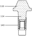
参考图4A和图4B,示例的碎裂组件100包括与固定器120可移动地连接的嵌入件110,固定器基本上不可移动地安装在工具承载器(或基块)200上,工具承载器可以连接到例如滚筒的挖掘设备上。嵌入件110包括连接到支撑体116的尖端112,其中支撑体116的主要部分包括钢,“向前”朝向部分(如通过箭头130所示)可包括防 磨结构1161,该结构包括比钢具有更高耐磨性的材料。支撑体116构造成是在前进方向上尽可能小的突起,如图4B所示,其具有降低使用时钢磨损量的作用。
Referring to FIGS. 4A and 4B , an
可提供包括固定器120和嵌入件110的碎裂组件100,用于碎裂本体(未显示),例如路面或岩层。固定器120和嵌入件110协作地构造为可操作地可移动地连接嵌入件110和固定器120,该嵌入件110可以设置有用于此目的的连接装置。嵌入件110包括用于破碎本体的尖端112和对准机构,当嵌入件在使用中利用力抵靠本体被驱动时,响应于在对准机构上施加反作用力的本体,对准机构可操作地迫使嵌入件110相对于固定器120移动。
如图5A和图5B所示,示例的碎裂组件可以包括嵌入件和固定器。在该示例的布置中,连接装置包括杆114,并且固定器120设置有用于接纳杆114的钻孔122。杆114和固定器122可协作地构造,以使嵌入件110可转动地安装在固定器120上。固定器120和嵌入件110具有各自的相对支承面1202和1162(当嵌入件110安装在固定器120中时)。在图5A和图5B图示的特别例子中,碎裂组件包括限制机构,该限制机构在一位置范围内可操作地限制可移动的连接装置。固定器120可以设置有从支承面1162伸出的凸起1101,固定器120可以设置有狭槽1201,该狭槽构造为接纳凸起1101并且允许该凸起在受限的路径中移动,在该特别的例子中该受限的路径通常是弧形的。当嵌入件110利用插入到钻孔122中的杆114安装在固定器120上时,凸起1101将插入到狭槽1201中。当嵌入件110被驱动以在固定器120的钻孔122内转动时,狭槽1201允许凸起1101在转动的界限之间移动,导致嵌入件110相对于固定器120的受限的转动。一些布置可以具有这样的方面,其中嵌入件110可以充分地转动以安置在期望的稳定结构,但是不会到使其朝向错误方向的程度。
As shown in FIGS. 5A and 5B , an example fragmentation assembly may include an insert and a retainer. In this example arrangement the connection means comprises a
在碎裂组件的示例布置中,固定器和连接装置合作地构造为在使 用中响应在嵌入件上施加反作用力的本体,阻止嵌入件相对于固定器的运动。参考图6至9中图示的示例装置,连接装置包括具有一般锥形部分的轴114,并且固定器120可以具有用于接纳该轴114的配合锥形钻孔122,如此构造,使得响应于被强制进入钻孔122的轴114,轴114将在钻孔122的端面上施加横向力。当以递增的力迫使轴114压入钻孔120中时,这种布置允许轴114,以及整个嵌入件110在固定器120内以递增的抵抗力转动。换句话说,当轴114被强制压入钻孔122中并且抵靠钻孔122的锥形侧壁时,摩擦将导致增加对轴114在钻孔122内转动的抵抗力。在使用中,该布置允许嵌入件110充分地转动以安置在稳定的结构,并且当嵌入件110与待被碎裂的本体接合时通过迫使嵌入件110进入钻孔122中而基本上保持该结构,从而加强连接装置114。
In an example arrangement of the fragmentation assembly, the retainer and connection means are cooperatively configured to, in use, resist movement of the insert relative to the retainer in response to the body exerting a counter force on the insert. Referring to the example device illustrated in FIGS. 6 to 9, the connection device includes a
在一些例子中,套筒140可以布置在连接装置114和钻孔122之间。例如,钻孔122通常为圆柱形并且大体上不成锥形,套筒140可以具有锥形内表面1401以容纳嵌入件110的锥形轴114。
In some examples,
下列分句用于进一步描述本申请公开的挖掘工具。 The following clauses are used to further describe the mining tools disclosed in the present application. the
1.一种用于包括固定器的碎裂组件的嵌入件,该嵌入件包括尖端,用于可移动地连接嵌入件和固定器的连接机构,以及对准机构,该对准机构可操作地迫使尖端朝向固定器内的对准方向移动;对准方向是相对于插入件在使用中被驱动的向前方向的。 1. An insert for a fragmentation assembly comprising a retainer, the insert comprising a tip, a coupling mechanism for movably connecting the insert and the retainer, and an alignment mechanism operable to The tip is forced towards an alignment direction within the holder; the alignment direction is relative to the forward direction in which the inserter is driven in use. the
2.根据分句1所述的嵌入件,当利用力抵靠本体驱动嵌入件时,响应于待被碎裂的本体施加在对准机构上的反作用力,对准机构可操作地促使尖端朝向对准方向移动。 2. An insert according to clause 1, when the insert is driven against the body by force, the alignment mechanism being operable to urge the tip towards Move in the right direction. the
3.根据分句1或2所述的嵌入件,其中连接机构包括用于插入到固定器的钻孔中的杆。 3. An insert according to clause 1 or 2, wherein the connection mechanism comprises a rod for insertion into a bore of the anchor. the
4.根据前述分句中任一项所述的嵌入件,其中对准机构包括尖端。 4. An insert according to any one of the preceding clauses, wherein the alignment mechanism comprises a tip. the
5.根据前述分句中任一项所述的嵌入件,其中连接机构包括杆,该杆限定纵向轴线;嵌入件构造为带有从该纵向轴线横向地偏移的尖端。 5. The insert according to any one of the preceding clauses, wherein the connecting mechanism comprises a rod defining a longitudinal axis; the insert being configured with a tip laterally offset from the longitudinal axis. the
6.根据前述分句中任一项所述的嵌入件,其中连接机构构造为可转动地连接嵌入件和固定器。 6. The insert according to any one of the preceding clauses, wherein the connection mechanism is configured to rotatably connect the insert and the retainer. the
7.根据前述分句中任一项所述的嵌入件,其中连接机构包括限定纵向轴线的杆,对准机构包括从纵向轴线横向地偏移的尖端;当杆插入到形成在固定器中的钻孔时,尖端和杆构造为可操作地允许尖端围绕由杆限定的纵向轴线的角位置(方位位置)变化。 7. The insert according to any one of the preceding clauses, wherein the connecting mechanism comprises a rod defining a longitudinal axis, and the alignment mechanism comprises a tip laterally offset from the longitudinal axis; When drilling, the tip and stem are configured to operably allow a change in the angular position (azimuth position) of the tip about a longitudinal axis defined by the stem. the
8.一种嵌入件,包括尖端,连接杆,具有近端和远端的支撑体,尖端连接到支撑体的近端,连接杆连接到支撑体的远端或者从支撑体的远端伸出;连接杆构造为可转动地将嵌入件连接到固定器,并且限定一纵向轴线;尖端从该纵向轴线横向地偏移。 8. An insert comprising a tip, a connecting rod, a support body having a proximal end and a distal end, the tip being connected to the proximal end of the support body, and the connecting rod being connected to or protruding from the distal end of the support body the connecting rod is configured to rotatably connect the insert to the fixture and defines a longitudinal axis; the tip is laterally offset from the longitudinal axis. the
9.根据前述分句中任一项所述的嵌入件,该嵌入件包括限制机构,当通过连接机构允许时,该限制机构可操作地限制嵌入件相对于固定器的运动程度。 9. An insert as claimed in any one of the preceding clauses, comprising a limiting mechanism operable to limit the extent of movement of the insert relative to the anchor when permitted by the connection mechanism. the
10.根据前述分句中任一项所述的嵌入件,其中连接机构包括限定纵向轴线的杆,对准机构包括从纵向轴线横向地偏移的尖端;当杆插入到形成在固定器中的钻孔时,尖端和杆构造为可操作地允许尖端围绕由杆限定的纵向轴线的角位置(方位位置)变化;嵌入件包括限制机构,该限制机构可操作地限制尖端围绕纵向轴线的转动程度。 10. The insert according to any one of the preceding clauses, wherein the connecting mechanism comprises a rod defining a longitudinal axis, and the alignment mechanism comprises a tip laterally offset from the longitudinal axis; When drilling, the tip and stem are configured to operably permit variation in the angular position (azimuth position) of the tip about a longitudinal axis defined by the stem; the insert includes a limiting mechanism operable to limit the degree of rotation of the tip about the longitudinal axis . the
11.根据前述分句中任一项所述的嵌入件,其中尖端包括超硬材料,例如合成或天然金刚石材料,例如PCD,碳化硅-结合金刚石材料或金刚石增强碳化物材料。 11. An insert according to any one of the preceding clauses, wherein the tip comprises a superhard material, such as synthetic or natural diamond material, eg PCD, silicon carbide-bonded diamond material or diamond reinforced carbide material. the
12.根据前述分句中任一项所述的嵌入件,其中尖端包括与硬质合金基底连结的PCD结构,并具有通常为圆锥形的工作端。 12. An insert according to any one of the preceding clauses, wherein the tip comprises a PCD structure bonded to a cemented carbide substrate and has a generally conical working end. the
13.根据前述分句中任一项所述的嵌入件,其中支撑体包括钢制 材料。 13. Insert according to any one of the preceding clauses, wherein the support body comprises a steel material. the
14.根据前述分句中任一项所述的嵌入件,其中支撑体包括防磨结构。 14. Insert according to any one of the preceding clauses, wherein the support body comprises a wear resistant structure. the
15.根据前述分句中任一项所述的嵌入件,其中连接机构构造为可操作地阻止或抵抗嵌入件相对于固定器的运动。 15. The insert according to any one of the preceding clauses, wherein the connection mechanism is configured to operatively prevent or resist movement of the insert relative to the anchor. the
16.根据前述分句中任一项所述的嵌入件,其中连接机构构造为响应于在连接机构上施加反作用力的本体,在使用中可操作地阻止或抵抗嵌入件相对于固定器的运动。 16. An insert as claimed in any one of the preceding clauses, wherein the attachment mechanism is configured to, in use, operatively prevent or resist movement of the insert relative to the anchor in response to a body exerting a reaction force on the attachment mechanism . the
17.根据前述分句中任一项所述的嵌入件,其中碎裂组件用于路面碎裂(道路整修)或采矿。 17. The insert according to any one of the preceding clauses, wherein the fragmentation assembly is used for pavement fragmentation (road repair) or mining. the
18.一种碎裂组件,该碎裂组件包括固定器和前述分句中任一项所述的嵌入件。 18. A fragmentation assembly comprising a retainer and an insert according to any preceding clause. the
19.根据分句18所述的碎裂组件,该碎裂组件用于路面碎裂或采矿。 19. A breaking assembly according to clause 18 for use in road breaking or mining. the
20.根据分句18或19所述的碎裂组件,该碎裂组件包括限制机构,当通过连接机构允许时,该限制机构可操作地限制嵌入件相对于固定器的运动程度。 20. A fragmentation assembly according to clause 18 or 19 comprising a restriction mechanism operable to restrict the extent of movement of the insert relative to the holder when permitted by the connection mechanism. the
21.根据分句18到20中任一项所述的碎裂组件,其中固定器和连接装置协作地构造为可操作地阻止或抵抗嵌入件相对于固定器的运动。 21. A fragmentation assembly according to any one of clauses 18 to 20, wherein the retainer and connection means are cooperatively configured to operably prevent or resist movement of the insert relative to the retainer. the
22.根据分句17至21中任一项所述的碎裂组件,其中固定器设置有用于接纳嵌入件的连接机构的钻孔;连接机构和钻孔被构造为当嵌入件与固定器连接时,允许嵌入件围绕由连接机构限定的纵向轴线转动。 22. A fragmentation assembly according to any one of clauses 17 to 21, wherein the retainer is provided with a bore for receiving the attachment means of the insert; the attachment means and the bore are configured so that when the insert is attached to the retainer , allowing the insert to rotate about the longitudinal axis defined by the connection mechanism. the
23.根据分句17到22中任一项所述的碎裂组件,其中当通过连接机构允许时,嵌入件和固定器协作地构造为可操作地限制嵌入件相对于固定器的运动程度,例如转动程度。 23. A fragmentation assembly according to any one of clauses 17 to 22, wherein the insert and holder are cooperatively configured to operatively limit the extent of movement of the insert relative to the holder when permitted by the connection mechanism, For example the degree of rotation. the
24.根据分句17到23中任一项所述的碎裂组件,其中嵌入件和固定器协作地构造为可操作地限制尖端围绕由连接机构限定的纵向轴线的转动程度;当尖端在使用中被向前驱动时,尖端被限制在纵向轴线的后方位置。 24. A fragmentation assembly according to any one of clauses 17 to 23, wherein the insert and retainer are cooperatively configured to operatively limit the degree of rotation of the tip about the longitudinal axis defined by the attachment mechanism; when the tip is in use The tip is constrained in a rearward position on the longitudinal axis when the center is driven forward. the
25.根据分句24所述的碎裂组件,其中尖端的转动限制在大约30度的弧形内。 25. The fragmentation assembly according to clause 24, wherein the rotation of the tip is limited to an arc of about 30 degrees. the
26.根据分句17到25中任一项所述的碎裂组件,还包括限制机构,其用于限制尖端围绕纵向轴线的运动程度,例如转动程度。 26. A fragmentation assembly according to any one of clauses 17 to 25, further comprising a limiting mechanism for limiting the degree of movement, eg rotation, of the tip about the longitudinal axis. the
27.根据分句17到26中任一项所述的碎裂组件,该碎裂组件构造为响应于纵向施加到嵌入件上的力或力分量,可操作地抵抗或阻止由连接机构允许的嵌入件运动。 27. A fragmentation assembly according to any one of clauses 17 to 26, which is configured to be operable to resist or prevent a force or force component applied longitudinally to the insert in response to Insert movement. the
28.根据分句27所述的碎裂组件,其中连接机构包括轴,该轴的至少一部分为锥形,固定器设置有钻孔,该钻孔具有其至少一部分是配合锥形的表面,该固定器响应于纵向施加在嵌入件上的力或力分量可操作地促使轴在钻孔的表面上施加横向力。 28. A fragmentation assembly according to clause 27, wherein the coupling mechanism comprises a shaft at least partly tapered, the retainer is provided with a bore having a surface at least partly matingly tapered, the The anchor is operable to cause the shaft to exert a lateral force on the surface of the borehole in response to a force or force component applied longitudinally to the insert. the
29.根据分句17至28中任一项所述的碎裂组件,其中嵌入件包括一轴,该轴的至少一部分设置为锥形,该锥形具有至少大约2度和至多大约45度的锥角,并且固定器设置有钻孔,该钻孔具有对应锥形的表面。 29. A fragmentation assembly according to any one of clauses 17 to 28, wherein the insert comprises a shaft, at least a portion of which is tapered, the taper having an angle of at least about 2 degrees and at most about 45 degrees cone angle, and the fixture is provided with a borehole with a correspondingly tapered surface. the
30.根据分句17到29中任一项所述的碎裂组件,其中连接机构包括杆,碎裂组件包括套筒,套筒配置为围绕杆的至少一部分。 30. The fragmentation assembly according to any one of clauses 17 to 29, wherein the connection mechanism comprises a rod and the fragmentation assembly comprises a sleeve configured to surround at least a part of the rod. the
31.一种碎裂设备,该碎裂设备包括根据分句17至30中任一项所述的碎裂组件,该碎裂组件基本上不可移动地与承载器装置(例如滚筒)连接。 31. Shredding apparatus comprising a shredding assembly according to any one of clauses 17 to 30, the shredding assembly being connected substantially immovably to carrier means, such as a drum. the
将在下文中更详细地描述碎裂组件的非限制性的实施例。 Non-limiting examples of fragmentation assemblies are described in more detail below. the
实施例 Example
下面提供一种用于沥青路面碎裂的示例挖掘工具组件,其包括嵌入件和用于嵌入件的固定器。 An example pick tool assembly for chipping asphalt pavements including an insert and a retainer for the insert is provided below. the
嵌入件包括尖端,用于可转动地连接嵌入件和固定器的连接杆,以及支撑体。尖端包括结合到烧结碳化钨基底的PCD结构,该尖端通过铜焊材料在支撑体的一端连接到支撑体。基底可以具有通常圆柱形的端面,该圆柱形端面具有大约6mm的横向(圆柱)直径。PCD结构可以通常形成为结合到基底的盖,PCD结构的主要部分具有球形的钝圆锥形外部形状,该钝圆锥形外部形状具有圆形的顶部,该顶部具有2.25mm的曲率半径(在纵向平面中)以及具有在与纵向轴线平行的轴线和PCD结构的外表面的锥形部分之间的42度的圆周角。PCD结构可以包括鼻部区域和裙部区域,裙部区域可纵向地和横向地远离鼻部区域。裙部区域的最小纵向厚度可以至少是1.45mm。在顶部的PCD结构的纵向厚度大约是4.5mm。 The insert includes a tip, a connecting rod for rotatably connecting the insert to the anchor, and a support body. The tip comprises a PCD structure bonded to a cemented tungsten carbide base, the tip being connected to the support at one end of the support by a brazing material. The base may have a generally cylindrical end surface with a transverse (cylindrical) diameter of approximately 6 mm. The PCD structure may generally be formed as a lid bonded to a substrate, the main part of the PCD structure having a spherical blunt conical outer shape with a rounded top with a radius of curvature of 2.25 mm (in the longitudinal plane middle) and having a circumferential angle of 42 degrees between an axis parallel to the longitudinal axis and the tapered portion of the outer surface of the PCD structure. The PCD structure may include a nose region and a skirt region, the skirt region being longitudinally and laterally remote from the nose region. The minimum longitudinal thickness of the skirt region may be at least 1.45 mm. The longitudinal thickness of the PCD structure at the top is approximately 4.5 mm. the
连接杆在与尖端连接在其上的一端相对的端部从支撑体伸出。连接杆通常可以是圆柱形,并且限定穿过支撑体的纵向轴线,尖端可以放置在支撑体上,使得尖端从纵向轴线横向地偏移(即尖端偏离纵向轴线),以使尖端的顶部距离纵向轴线大约4mm。纵向轴线可以穿过尖端,但是基本上与尖端的顶部间隔开。 The connecting rod projects from the support body at the end opposite to the end to which the tip is connected. The connecting rod may be generally cylindrical and define a longitudinal axis passing through the support on which the tip may be placed such that the tip is laterally offset from the longitudinal axis (i.e., the tip is offset from the longitudinal axis) so that the top of the tip is 1000° from the longitudinal axis. The axis is about 4mm. The longitudinal axis may pass through the tip, but is substantially spaced from the top of the tip. the
支撑体可以包括钢并设置有磨损防护结构,该磨损防护结构包括配置在支撑体的前面上的硬质合金,该前面是在使用中朝向路面的面。支撑体通常可以设置有凹形侧面,以使降低了面向前的面积。固定器可以设置有钻孔,该钻孔构造为容纳嵌入件的连接杆,以使连接杆可以在钻孔内转动,因此,嵌入件可以相对于固定器转动。固定器可以设置有不可转动地固定到基块的杆,该基块焊接到路面碎裂滚筒。 The support body may comprise steel and be provided with a wear protection structure comprising cemented carbide arranged on the front face of the support body, which is the face facing the road in use. The support body may generally be provided with concave sides so that the front facing area is reduced. The anchor may be provided with a bore configured to receive a connecting rod of the insert so that the connecting rod may be rotated within the bore and, therefore, the insert may be rotated relative to the retainer. The holder may be provided with a rod fixed non-rotatably to a base block welded to the pavement breaking drum. the
在上面已经描述了挖掘工具和用于装配和连接它们的方法的多个示例的实施例。本领域技术人员应当理解的是,在不脱离本发明权利要求的精神和范围的情况下可以对那些示例进行改变和修改。 Several exemplary embodiments of pick tools and methods for assembling and connecting them have been described above. It will be understood by those skilled in the art that changes and modifications may be made to those examples without departing from the spirit and scope of the present invention claimed. the
在下文中简要地说明在本文中使用的一些术语。 Some of the terms used in this paper are briefly explained below. the
如在本文中使用的,"超硬"指的是至少25GPa的维氏硬度,且超硬工具、嵌入件或元件指的是包括超硬材料的工具、嵌入件和元件。 As used herein, "superhard" refers to a Vickers hardness of at least 25 GPa, and superhard tools, inserts or components refer to tools, inserts and components comprising superhard materials. the
合成和天然金刚石,多晶金刚石(PCD),立方氮化硼(cBN)和多晶cBN(PCBN)材料是超硬材料的例子。合成金刚石,也称为人造金刚石,是已经制成的金刚石材料。多晶金刚石(PCD)材料包括大量(多个的聚集体)金刚石晶粒,其主要部分是直接相互彼此内结合的,且其中金刚石的体积含量是材料的至少大约80%。在金刚石晶粒之间的空隙可以至少部分地填充有粘合剂材料,该粘合剂材料包括用于合成金刚石的催化剂材料,或者这些空隙可以大体上是空的。用于合成金刚石的催化剂材料能够在合成或天然金刚石在热力学上比石墨更加稳定的温度和压力下促进合成金刚石晶粒的生长,和/或合成或天然金刚石粒的直接的内生长。用于金刚石的催化剂材料的例子是Fe,Ni,Co和Mn,以及包括这些元素的一些合金。包括PCD材料的物体可以包括至少一个区域,在该区域中催化剂材料已经从空隙移除,在金刚石晶粒之间留下间隙空位。如在本文中使用,PCBN材料包括分散在包括金属和/或陶瓷材料的基体内的立方氮化硼(cBN)晶粒。 Synthetic and natural diamond, polycrystalline diamond (PCD), cubic boron nitride (cBN) and polycrystalline cBN (PCBN) materials are examples of superhard materials. Synthetic diamond, also known as man-made diamond, is diamond material that has been made. Polycrystalline diamond (PCD) material comprises a plurality (agglomerates) of diamond grains, a major portion of which are directly internally bonded to one another, and wherein the volume fraction of diamond is at least about 80% of the material. The interstices between the diamond grains may be at least partially filled with a binder material comprising catalyst material for synthesizing the diamond, or the interstices may be substantially empty. Catalyst materials for synthetic diamond are capable of promoting the growth of synthetic diamond grains, and/or direct ingrowth of synthetic or natural diamond grains, at temperatures and pressures at which synthetic or natural diamond is thermodynamically more stable than graphite. Examples of catalyst materials for diamond are Fe, Ni, Co and Mn, and some alloys including these elements. Objects comprising PCD material may comprise at least one region in which catalyst material has been removed from the interstices, leaving interstitial vacancies between diamond grains. As used herein, PCBN material comprises cubic boron nitride (cBN) grains dispersed within a matrix comprising metallic and/or ceramic material. the
超硬材料的其他的例子包括某些复合材料,该复合材料包括通过包含陶瓷材料(例如碳化硅(SiC))或硬质合金材料(例如,钴结合WC材料(例如,如编号为5,453,105或6,919,040的美国专利中描述的))的基体保持在一起的金刚石或cBN晶粒。例如,某些碳化硅结合金刚石材料可以包括分散在SiC基体(其可以包括少量的除了碳化硅的形式之外的硅)中的至少大约30体积百分比的金刚石晶粒。在美国专利编号7,008,672、6,709,747、6,179,886、6,447,852以及国际申请公开编号WO2009/013713中描述了碳化硅结合金刚石材料的例子。 Other examples of superhard materials include certain composite materials comprising ceramic materials such as silicon carbide (SiC) or cemented carbide materials such as cobalt bonded WC materials such as described in the US patent)) the matrix holds together the diamond or cBN grains. For example, certain silicon carbide bonded diamond materials may include at least about 30 volume percent diamond grains dispersed in a SiC matrix (which may include small amounts of silicon other than in the form of silicon carbide). Examples of silicon carbide bonded diamond materials are described in US Patent Nos. 7,008,672, 6,709,747, 6,179,886, 6,447,852 and International Application Publication No. WO2009/013713. the
Claims (14)
Applications Claiming Priority (5)
| Application Number | Priority Date | Filing Date | Title |
|---|---|---|---|
| US201161445984P | 2011-02-23 | 2011-02-23 | |
| GBGB1103096.2A GB201103096D0 (en) | 2011-02-23 | 2011-02-23 | Insert and degradation assembly |
| GB1103096.2 | 2011-02-23 | ||
| US61/445,984 | 2011-02-23 | ||
| PCT/EP2012/052695 WO2012113707A2 (en) | 2011-02-23 | 2012-02-16 | Insert and degradation assembly |
Publications (1)
| Publication Number | Publication Date |
|---|---|
| CN103502572A true CN103502572A (en) | 2014-01-08 |
Family
ID=43881531
Family Applications (1)
| Application Number | Title | Priority Date | Filing Date |
|---|---|---|---|
| CN201280015536.XA Pending CN103502572A (en) | 2011-02-23 | 2012-02-16 | Self-aligning insert and degradation assembly |
Country Status (8)
| Country | Link |
|---|---|
| EP (1) | EP2678526A2 (en) |
| CN (1) | CN103502572A (en) |
| AU (1) | AU2012219742A1 (en) |
| CA (1) | CA2827914A1 (en) |
| DE (1) | DE112012000963T5 (en) |
| GB (2) | GB201103096D0 (en) |
| RU (1) | RU2013142994A (en) |
| WO (1) | WO2012113707A2 (en) |
Families Citing this family (4)
| Publication number | Priority date | Publication date | Assignee | Title |
|---|---|---|---|---|
| GB201201120D0 (en) | 2012-01-24 | 2012-03-07 | Element Six Abrasives Sa | Pick tool and assembly comprising same |
| GB201215555D0 (en) * | 2012-08-31 | 2012-10-17 | Element Six Gmbh | Pick assembly, bit assembly and degradation tool |
| DE102012108935A1 (en) * | 2012-09-21 | 2014-03-27 | Thyssenkrupp Resource Technologies Gmbh | Arrangement of a crushing tooth on a crushing roller of a roll crusher |
| GB201320501D0 (en) | 2013-11-20 | 2014-01-01 | Element Six Gmbh | Strike constructions,picks comprising same and methods for making same |
Citations (4)
| Publication number | Priority date | Publication date | Assignee | Title |
|---|---|---|---|---|
| GB1082362A (en) * | 1964-01-17 | 1967-09-06 | Coal Industry Patents Ltd | Mineral cutting tools |
| GB2137263A (en) * | 1983-03-30 | 1984-10-03 | Tungsten Carbide Developments | Mineral cutter pick and box |
| DE3403344A1 (en) * | 1984-02-01 | 1985-08-01 | Belzer-Dowidat Gmbh Werkzeug-Union, 5600 Wuppertal | DISMANTLING TOOL |
| US20050088034A1 (en) * | 2003-10-23 | 2005-04-28 | Clemenson Enterprises, Inc. | Tool bit assembly with offset tooth |
Family Cites Families (11)
| Publication number | Priority date | Publication date | Assignee | Title |
|---|---|---|---|---|
| GB191401930A (en) * | 1914-01-24 | 1914-10-08 | Mavor & Coulson Ltd | Improvements in or connected with Cutters for Bars, Discs, and the like, and Cutter Bars, Discs, and the like, of Machines for use in Mining. |
| ZA935524B (en) | 1992-08-05 | 1994-02-24 | De Beers Ind Diamond | Abrasive product |
| WO1999012866A1 (en) | 1997-09-05 | 1999-03-18 | Frenton Limited | Method of manufacturing a diamond-silicon carbide-silicon composite and a composite produced by this method |
| US6709747B1 (en) | 1998-09-28 | 2004-03-23 | Skeleton Technologies Ag | Method of manufacturing a diamond composite and a composite produced by same |
| US6447852B1 (en) | 1999-03-04 | 2002-09-10 | Ambler Technologies, Inc. | Method of manufacturing a diamond composite and a composite produced by same |
| US6919040B2 (en) | 2000-08-08 | 2005-07-19 | Robert Fries | Method of producing an abrasive product containing cubic boron nitride |
| DE10161713B4 (en) | 2001-12-15 | 2004-02-05 | Wirtgen Gmbh | Chisel holder changing system |
| DE102004057302B4 (en) | 2004-11-26 | 2011-01-13 | Wirtgen Gmbh | toolholders |
| US8109349B2 (en) | 2006-10-26 | 2012-02-07 | Schlumberger Technology Corporation | Thick pointed superhard material |
| US8136887B2 (en) | 2006-08-11 | 2012-03-20 | Schlumberger Technology Corporation | Non-rotating pick with a pressed in carbide segment |
| WO2009013713A2 (en) | 2007-07-23 | 2009-01-29 | Element Six (Production) (Pty) Ltd | Abrasive compact |
-
2011
- 2011-02-23 GB GBGB1103096.2A patent/GB201103096D0/en not_active Ceased
-
2012
- 2012-02-16 CN CN201280015536.XA patent/CN103502572A/en active Pending
- 2012-02-16 CA CA2827914A patent/CA2827914A1/en not_active Abandoned
- 2012-02-16 EP EP12704091.3A patent/EP2678526A2/en not_active Withdrawn
- 2012-02-16 DE DE112012000963.0T patent/DE112012000963T5/en not_active Withdrawn
- 2012-02-16 RU RU2013142994/03A patent/RU2013142994A/en not_active Application Discontinuation
- 2012-02-16 GB GB201202650A patent/GB2488408B8/en not_active Expired - Fee Related
- 2012-02-16 WO PCT/EP2012/052695 patent/WO2012113707A2/en not_active Ceased
- 2012-02-16 AU AU2012219742A patent/AU2012219742A1/en not_active Abandoned
Patent Citations (4)
| Publication number | Priority date | Publication date | Assignee | Title |
|---|---|---|---|---|
| GB1082362A (en) * | 1964-01-17 | 1967-09-06 | Coal Industry Patents Ltd | Mineral cutting tools |
| GB2137263A (en) * | 1983-03-30 | 1984-10-03 | Tungsten Carbide Developments | Mineral cutter pick and box |
| DE3403344A1 (en) * | 1984-02-01 | 1985-08-01 | Belzer-Dowidat Gmbh Werkzeug-Union, 5600 Wuppertal | DISMANTLING TOOL |
| US20050088034A1 (en) * | 2003-10-23 | 2005-04-28 | Clemenson Enterprises, Inc. | Tool bit assembly with offset tooth |
Also Published As
| Publication number | Publication date |
|---|---|
| RU2013142994A (en) | 2015-03-27 |
| WO2012113707A2 (en) | 2012-08-30 |
| GB2488408B (en) | 2013-08-14 |
| GB2488408A8 (en) | 2013-10-16 |
| GB2488408B8 (en) | 2013-10-16 |
| GB2488408A (en) | 2012-08-29 |
| DE112012000963T5 (en) | 2014-02-20 |
| WO2012113707A3 (en) | 2013-03-28 |
| GB201202650D0 (en) | 2012-04-04 |
| AU2012219742A1 (en) | 2013-10-03 |
| GB201103096D0 (en) | 2011-04-06 |
| EP2678526A2 (en) | 2014-01-01 |
| CA2827914A1 (en) | 2012-08-30 |
Similar Documents
| Publication | Publication Date | Title |
|---|---|---|
| US7588102B2 (en) | High impact resistant tool | |
| US20120242136A1 (en) | Cutting Tool | |
| US20040026983A1 (en) | Monolithic point-attack bit | |
| US20040065484A1 (en) | Diamond tip point-attack bit | |
| US7469972B2 (en) | Wear resistant tool | |
| EP2900917B1 (en) | Strike tip for a pick tool having a flat apex area | |
| US20100244545A1 (en) | Shearing Cutter on a Degradation Drum | |
| US11391148B2 (en) | Cutting assembly | |
| CN102905819B (en) | Take instrument and manufacture method thereof | |
| US20210032988A1 (en) | Cutting assembly | |
| US9458607B2 (en) | Rotatable cutting tool with head portion having elongated projections | |
| US20210003006A1 (en) | Cutting assembly | |
| CN103534415A (en) | Pick assembly, pick holder for same, pick tool for same and strike element for same | |
| CN107420046A (en) | Rotatable cutting tool with cutting tip and backing plate | |
| CN103502572A (en) | Self-aligning insert and degradation assembly | |
| US20180238170A1 (en) | Asymmetric pick tool with an aspect ratio between leading and trailing edges | |
| US9334732B2 (en) | Pick tool assembly and method of using same | |
| US20130300183A1 (en) | Multi-Faced Cutting Tool | |
| US20130307317A1 (en) | Cutting Bit With Split Wear Ring | |
| US9033424B2 (en) | Wear resistant cutting tool | |
| US20160024918A1 (en) | Universal Pick Adapter | |
| CN121358929A (en) | Cutting pick tool |
Legal Events
| Date | Code | Title | Description |
|---|---|---|---|
| C06 | Publication | ||
| PB01 | Publication | ||
| C10 | Entry into substantive examination | ||
| SE01 | Entry into force of request for substantive examination | ||
| C02 | Deemed withdrawal of patent application after publication (patent law 2001) | ||
| WD01 | Invention patent application deemed withdrawn after publication |
Application publication date: 20140108 |