CN103502095A - High lift system for aircraft and method for influencing high lift characteristics of aircraft - Google Patents
High lift system for aircraft and method for influencing high lift characteristics of aircraft Download PDFInfo
- Publication number
- CN103502095A CN103502095A CN201280020819.3A CN201280020819A CN103502095A CN 103502095 A CN103502095 A CN 103502095A CN 201280020819 A CN201280020819 A CN 201280020819A CN 103502095 A CN103502095 A CN 103502095A
- Authority
- CN
- China
- Prior art keywords
- wing flap
- holding element
- matrix
- edge
- lift system
- Prior art date
- Legal status (The legal status is an assumption and is not a legal conclusion. Google has not performed a legal analysis and makes no representation as to the accuracy of the status listed.)
- Granted
Links
- 238000000034 method Methods 0.000 title claims description 15
- 239000011159 matrix material Substances 0.000 claims description 49
- 238000004804 winding Methods 0.000 claims description 4
- 238000005452 bending Methods 0.000 claims description 3
- 239000000835 fiber Substances 0.000 claims 5
- 125000000962 organic group Chemical group 0.000 claims 2
- 238000009954 braiding Methods 0.000 claims 1
- 239000002131 composite material Substances 0.000 claims 1
- 150000001875 compounds Chemical class 0.000 claims 1
- 230000002349 favourable effect Effects 0.000 description 11
- 239000000463 material Substances 0.000 description 3
- 239000004952 Polyamide Substances 0.000 description 2
- 238000010586 diagram Methods 0.000 description 2
- 238000009434 installation Methods 0.000 description 2
- 229920002647 polyamide Polymers 0.000 description 2
- 230000001105 regulatory effect Effects 0.000 description 2
- 230000001419 dependent effect Effects 0.000 description 1
- 238000005516 engineering process Methods 0.000 description 1
- 239000002184 metal Substances 0.000 description 1
- 239000007769 metal material Substances 0.000 description 1
- 239000004033 plastic Substances 0.000 description 1
- 239000013589 supplement Substances 0.000 description 1
- 230000001360 synchronised effect Effects 0.000 description 1
- 210000002268 wool Anatomy 0.000 description 1
Images


Classifications
-
- B—PERFORMING OPERATIONS; TRANSPORTING
- B64—AIRCRAFT; AVIATION; COSMONAUTICS
- B64C—AEROPLANES; HELICOPTERS
- B64C9/00—Adjustable control surfaces or members, e.g. rudders
- B64C9/14—Adjustable control surfaces or members, e.g. rudders forming slots
- B64C9/22—Adjustable control surfaces or members, e.g. rudders forming slots at the front of the wing
-
- B—PERFORMING OPERATIONS; TRANSPORTING
- B64—AIRCRAFT; AVIATION; COSMONAUTICS
- B64C—AEROPLANES; HELICOPTERS
- B64C9/00—Adjustable control surfaces or members, e.g. rudders
- B64C9/02—Mounting or supporting thereof
-
- B—PERFORMING OPERATIONS; TRANSPORTING
- B64—AIRCRAFT; AVIATION; COSMONAUTICS
- B64C—AEROPLANES; HELICOPTERS
- B64C9/00—Adjustable control surfaces or members, e.g. rudders
- B64C9/14—Adjustable control surfaces or members, e.g. rudders forming slots
- B64C2009/143—Adjustable control surfaces or members, e.g. rudders forming slots comprising independently adjustable elements for closing or opening the slot between the main wing and leading or trailing edge flaps
Landscapes
- Engineering & Computer Science (AREA)
- Aviation & Aerospace Engineering (AREA)
- Transmission Devices (AREA)
- Auxiliary Methods And Devices For Loading And Unloading (AREA)
- Tires In General (AREA)
Abstract
A high lift system (16) for an aircraft comprises a basic body (20), a flap (18) which is movably mounted on the basic body (20) and has a flap edge (22), and a retaining element (26). The high lift system (16) is set up to form a gap (32) between the flap edge (22) and the basic body (20). The retaining element (26) is mounted on a region of the flap (18) close to the flap edge (22) and extends towards the basic body (20) to restrict the distance between the flap edge (22) and the basic body (20). The retaining element (26) is preferably configured as a linear attachment means. Consequently, a gap dimension between a flap (18) and a basic body (20) can be influenced to restrict flexing effects during loading of the flap (18) and of the basic body (20).
Description
Quoting of related application
The application require the German patent application submitted on April 28th, 2011 No.102011018906.8's and the U.S. Provisional Patent Application No.61/479 that submits on April 28th, 2011, the rights and interests of 925 the applying date, the disclosure of these applications is incorporated to this paper at this by reference.
Technical field
The present invention relates to a kind of high-lift system for aircraft and a kind of method that affects the high lift characteristic of aircraft.
Background technology
In order to realize predetermined air dynamic behaviour, the vehicle and particularly aircraft have the system of flaps usually, in the system of flaps, wing flap is arranged on matrix in the mode that can move and wing flap can enter clear position and enter different control positioies to affect around the air-flow of the vehicle or power is applied on the vehicle by actuator.For example, commercial aircraft has the appreciiable different system of flaps arranged for the different purposes of using.
The purpose of the high-lift system of aircraft is for example for taking off and the landing stage realizes by enlarger blade area and the camber that increases wing the lift coefficient enlarged markedly.For this purpose, suitable wing flap is arranged on the leading edge and trailing edge of wing in the mode that can move.For in the situation that the extra high angle of attack is realized separating of air-flow with low especially flying speed, wing flap usually can move and make gap be formed between wing flap and wing, thereby allows to produce the high-energy air-flow on the upside of wing.
In order to realize that such gap forms the optimized operation of the system of flaps, be necessary that, the gap size of realizing when wing flap bears the air load is identical with desired size.Especially, when wing flap is configured to the droope snoot as wing---wherein between the leading edge of the rear part edge of droope snoot and wing, produced gap, the air load makes the leading edge distortion of wing flap, and result has affected gap size.Due to installation and the guiding being distributed in the independent so-called driving station place droope snoot on the leading edge of wing, a zone of droope snoot or more zone location become almost to be fixed in the space of front of wing, can have a plurality of differently curved lines in the adjacent zone of droope snoot simultaneously.This distortion of droope snoot is not subject to the impact of the distortion of wing, makes under limiting case, has too small or excessive gap size in some zones of the conventional system of flaps between the leading edge of droope snoot and wing.
Overview about the prior art of the configuration of high-lift components can for example be found in the NASA contractor report 4746 of being shown by Peter K.C.Rudolph " about the high-lift system (High lift Systems on Commercial Subsonic Airliners) of commercial subsonic aircraft ".
Summary of the invention
Realization is very important for the predefined air dynamic behaviour of the system of flaps of the vehicle, particularly in the situation that the safety of the system of flaps-key application.Therefore, the objective of the invention is to propose a kind of high-lift system for aircraft, this high-lift system comprises matrix and wing flap, wing flap is arranged on matrix in the mode that can move, and this wing flap has the wing flap edge, the wing flap edge can move to make between wing flap edge and matrix and can form gap, and opening along wing flap of described gap keeps accurate as far as possible and constant as far as possible and directed partly with the tolerance of being scheduled to.
The high-lift system of the feature by having independent claims 1 is realized this purpose.Favourable development program is provided in the dependent claims.High-lift system according to the present invention for aircraft comprises matrix, wing flap and holding element, and this wing flap is arranged on matrix in the mode that can move and has the wing flap edge.High-lift system is provided between wing flap edge and matrix and forms gap.Holding element is arranged on the zone at close wing flap edge of wing flap and extends to the attachment point on matrix, makes the wing flap edge can be by holding element be pulled and/or crooked with the distance between restriction wing flap edge and matrix along the direction of matrix.
Therefore, high-lift system supplements by holding element, and the purpose of holding element is the gap size that restriction is limited by the distance between wing flap edge and matrix.The gap size changed due to air load and chatter phenomena can at least be restricted to predetermined length for unallowed increase by holding element.
Holding element can be realized with multitude of different ways.Due to wing flap, with respect to matrix, in the mode that can move, install and the motion at wing flap edge can limit by pulling force, for holding element and stark suitable be to be configured to receive especially pulling force.By this way, can use the flexible holding element of motion backward of non resistance wing flap.
Holding element also can be configured so that holding element between the moving period of wing flap, shorten or make holding element move to matrix in move to wing flap in or move in matrix and wing flap.For this purpose, matrix and/or wing flap must have the suitable access portal of the relative motion that allows holding element.If wing flap is constructed to Kr ü ger wing flap, opening can be arranged in the zone at wing flap edge.
In favourable embodiment, under extension state, wing flap is installed or is remained on the site that is away from holding element, make when holding element along the direction of matrix be pulled and/or when crooked this site along the direction of matrix, do not move.This means that wing flap can be with respect to the attachment point limited by kinematics and mobile and also aim at by holding element at this place or fastening.
In the present invention in favourable embodiment, holding element is arranged on shift equipment, this shift equipment is arranged as and makes holding element fastening and provide and extend the free end leave shift equipment at the first end place, this end apart from the distance of shift equipment can be by shift equipment self individually and can regulate with changing.At this on the one hand, the free end of holding element can be arranged on the submarginal zone of wing flap, and shift equipment is arranged in matrix and originally is arranged in it or preferably in matrix itself, and holding element extends towards the wing flap edge from matrix with its free end.Simultaneously, in a preferred embodiment, shift equipment can also be arranged in the zone near the wing flap edge, makes the free end of holding element extend wing flap by access portal and towards matrix, and the free end of holding element is mounted at the matrix place or is fastening subsequently.
The operation shift equipment is the distance between regulating flap edge and matrix or to the distance limit between major general's wing flap edge and matrix in upperlimit on one's own initiative.In the preferred embodiment of the present invention, holding element is configured to dimensionally elastomeric and flexible wire attachment arrangement and holding element is set to absorb pulling force especially.Such holding element can be configured to rope, line/metal wool, string etc., and the selection of material should be guided by some marginal conditions.These conditions especially are the wide especially range of temperatures that holding element is experienced during installation.Especially, when such high-lift system, on commercial aircraft the time, on wing structure, temperature can rise, range of temperatures-50 ℃ and+60 ℃ between.Although external temperature is not in limit when such high-lift system is used on aircraft, it should be noted that, when aircraft waits and bides one's time on the ground at hot weather, holding element reaches specific temperature, and this specified temp will cause at high-lift system the initial tensile strength reduced between the starting period.Simultaneously, during the cruising flight of aircraft, such holding element can be cooled to sizable degree, and to make the initial elasticity between the starting period at high-lift system will be that risk too low and that tear---due to tendency of brittle fracture---will be greater than for example risk in room temperature after cruising flight.Recommend, as the metallic material in particular of the suitable material for holding element, for example to weave wirerope, and high-tenacity that in addition can anti-previously mentioned range of temperatures/pulling force plastic material, for example polyamide or glass-fiber-reinforced polyamide.
In favourable embodiment of the present invention, shift equipment comprises coiling body, holding element is attached by first end on coiling body, coiling body is arranged to continuous drawing (stretching) power is applied on holding element, this pulling force does not stop holding element to launch from coiling body, and allows to be wound to independently on described coiling body simultaneously.By presetting the rotation of mechanical maximum possible, shift equipment will be for the synchronous memory device of holding element with for regulating the device of gap size on actual term.So holding element will be embodied as wire attachment arrangement outward extending from coiling body and that extend by access portal.Coiling body can also be configured to traction winch, and driver element is incorporated in this traction winch, and coiling body is also the rotation of ratchet to prevent from not expecting alternatively.
In favourable embodiment of the present invention, shift equipment comprises revolving actuator, and this revolving actuator is attached to coiling body so that the coiling holding element.Therefore, power can be applied on holding element on one's own initiative, for example makes when wing flap moves to clear position, and holding element synchronously is wound on coiling body and does not therefore affect the motion of wing flap.
In the present invention, in favourable embodiment, revolving actuator is configured to spring element, and this spring element is configured such that coiling body bears enough the moment of torsion for the holding element of reeling.This has following favourable effect: for holding element, do not need main drive constantly to follow the tracks of mobile wing flap.This means when wing flap is contracted, holding element in fact automatically is back to according to nondestructive clear position of aerodynamics viewpoint etc.
In the present invention, in favourable embodiment, coiling body only can be rotated into as far as specific, and coiling body has and prevents that holding element is pulled out retainer too far away.In the concrete configuration of high-lift system, this is at the upperlimit that presets gap and preventing that the outwardly-bent of wing flap from being enough aspect the increase gap.
In the present invention, in favourable embodiment, revolving actuator is electric actuator, hydraulic actuator or the pneumatic actuator of mobile coiling body on one's own initiative.When relevant wing flap is carried out when significant especially motion of translation and torsion spring can not be guaranteed the constant pulling force on the whole length at holding element, this is useful especially.For example, electric driving, preferably have the electric driving of driving device, can be considered for this purpose.
In favourable embodiment, holding element is connected to the machine security unit, in the situation that overload, this machine security unit separates wing flap with holding element.Therefore, if holding element remains on original place, can prevent the damage to wing flap.
Be understandable that, high-lift system according to the present invention is not limited to the use of single holding element.Alternatively, will will be advantageous that, such a plurality of holding elements are distributed and limited the possible distortion at the various discrete point place of wing flap or a plurality of wing flaps in whole high-lift system along whole wing flap.The length of holding element can be scheduled to by adjusting on the ground.
High-lift system according to the present invention preferably includes the Kr ü ger wing flap that can enter retracted mode and at least one extension state.Under retracted mode, Kr ü ger wing flap is arranged to concordant in the recess on the downside of matrix and can rotates by rotatablely moving around pivot, and this pivot is preferably located in the outside of Kr ü ger wing flap so that enter extension state.Use the arrangement form of such high-lift system, when wing flap extends, from the wing flap edge with respect to the constant distance of matrix, produce.Therefore, use the arrangement form of holding element, the development length of holding element can be restricted to and make when high-lift system starts fully, has realized the ultimate range between the front edges of the trailing edge of wing flap and matrix.
Further realized above-mentioned purpose by the method for the high lift characteristic for affecting aircraft, the method comprises: make the high lift wing flap of aircraft extend to the step of extended position from retracted position, the high lift wing flap has the wing flap edge, and this wing flap edge forms gap at extended position and the matrix of wing flap between wing flap edge and matrix; And extend along the step at direction tractive and/or the crooked wing flap edge of matrix by the holding element extended between wing flap edge and matrix.
In the favourable embodiment of method, when the high lift wing flap is extended and extend holding element by shift equipment.In the method according to the invention, the high lift wing flap preferably moves to retracted position with the high-lift system of stopping using, and holding element is preferably retracted simultaneously.Aspect this, the retraction of holding element and extend preferably to relate to holding element is wound on the winding element of installing in rotatable mode and by holding element and launches from the winding element of installing in rotatable mode.
The accompanying drawing explanation
Other feature of the present invention, advantage and possible use are provided in the description of following embodiment and accompanying drawing.In aspect this, all features of description and/form that graphically illustrates, itself or in any combination way, theme of the present invention, no matter also its composition in each single claim or its backward reference.In addition, same reference numerals in the accompanying drawings represents same or similar object.
Fig. 1 a to Fig. 1 d shows the high-lift system that comprises the wire holding element according to of the present invention.
Fig. 2 shows the substituting high-lift system that comprises the wire holding element according to of the present invention.
Fig. 3 shows the aircraft comprised according to high-lift system of the present invention.
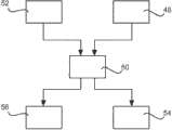
The schematic diagram based on square frame that Fig. 4 is the method according to this invention.
The specific embodiment
Fig. 1 shows according to high-lift system 16 of the present invention, in high-lift system 16, Kr ü ger wing flap 18 can be with respect to the wing 20 of the example as matrix and the reception position 21 from the downside at wing 20 outwards move.The free end 24 of holding element 26 is arranged on the edge 22 of wing flap.This for example can be by being fixedly connected with and realizing with point-like between wing flap 18 at free end 24 in submarginal regional 22.
The 22 position, edge that the obtainable length of restriction holding element 26 can limit wing flap 18.Therefore, wing flap 18 can only be deformed, and makes gap 32 only to be reduced and can not be extended.In addition, the motion at edge 22 can be followed the motion of matrix 20.If can select to have the coiling body as shown in Fig. 1 d 29 of rotation axis 27 diameter, make incomplete rotation that the sufficient length of holding element 26 will enough be provided, arranging of the retainer 31 corresponding with retainer on structure 36 will be easily with the extendible length of restriction holding element 26.
Shown in Fig. 2 and will move in the situation that the significant motion of translation of the wing flap 42 on the upside of wing 20, the opening 44 that is arranged in the upside of wing 20 will be the essential edge 41 with the supporting wing flap.Due to the significant translation of holding element 26 with due to the angle of attack---not drawn on scale/holding element---inhibition of the vibration at wing flap edge 41 is compared with the situation of Kr ü ger wing flap 18 shown in Fig. 1 a will be slightly more inapparent.
Fig. 3 shows the aircraft 46 that is equipped with such high- lift system 16,43.
Finally, Fig. 4 is the schematic diagram based on square frame of the possible order of the method for the high lift characteristic that affects aircraft according to the present invention.In order to start high-lift system, the high lift wing flap 18,42 of aircraft moves to extended position 48 from retracted position.At this on the one hand, high lift wing flap 18,42 has wing flap edge 22,41, and this wing flap edge 22,41 has formed the gap 32 between wing flap edge 22,41 and matrix 20 at extended position and the matrix 20 of high lift wing flap 18,42, as previously described in detail.Simultaneously or subsequently, by holding element 26, the direction along matrix 20 is bent or tractive 50 at wing flap edge 22,41, holding element 26 extends between wing flap edge 22,41 and matrix 20.When high lift wing flap 18,42 extends, holding element 26 can extend 52 by shift equipment, and this extends preferably generation simultaneously.For the high-lift system of stopping using, high lift wing flap 18,42 moves to retracted position 54, and holding element 26 is contracted 56 simultaneously.Retraction process and extension process can be launched to carry out from coiling body by holding element being wound on coiling body and by holding element.
In addition, it should be pointed out that " comprising (comprising) " do not get rid of any other element or step, and " one (one) " or " not indicating odd number or the situation (a/an) of plural number " do not get rid of plural number.It should also be noted that the feature of describing with reference to an embodiment in embodiment above also can be used in combination with other features of above-described other embodiments.Reference numeral in the claims should not be considered to restriction.
List of numerals
16 high-lift systems
18 wing flaps
20 wings
21 reception positions
22 wing flap edges
24 free ends
26 holding elements
27 rotation axiss
28 coiling bodies
30 coiling surfaces
31 retainers
32 gaps
34 torsion springs
36 structures
38 driven ends
40 openings
41 wing flap edges
42 wing flaps
43 systems of flaps
44 openings
46 aircraft
The extension of 48 (high lift) wing flap
Tractive/the bending at 50 wing flap edges
The extension of 52 holding elements
The retraction of 54 (high lift) wing flap
The retraction of 56 holding elements
Claims (14)
1. the high-lift system for aircraft (16,43), comprise
-matrix (20),
-wing flap (18,42), described wing flap (18,42) movably is arranged on described matrix (20) above and has wing flap edge (22,41), and
-holding element (26),
Wherein, the system of flaps (16,43) is arranged between described wing flap edge (22,41) and described matrix (20) and forms gap (32),
Described holding element (26) is arranged in the zone at close described wing flap edge (22,41) of described wing flap (18,42) and extends to limit the distance between described wing flap edge (22,41) and described matrix (20) towards described matrix (20), makes described wing flap edge (22,41) direction along described matrix (20) to be pulled and/or bending by described holding element (26).
2. high-lift system according to claim 1 (16,43), also comprise shift equipment, and described shift equipment is arranged to make described holding element (26) fastening and have and extend the free end that leaves described shift equipment at the first end place.
3. high-lift system according to claim 2 (16,43), wherein, described shift equipment is arranged in described matrix (20).
4. high-lift system according to claim 2 (16,43), wherein, described shift equipment is arranged in described wing flap (18,42).
5. according to the described high-lift system of any one in claim 2 to 4 (16,43), wherein, described holding element (26) is the wire attachment arrangement, and described shift equipment comprises the coiling body of installing in rotatable mode (28,29) for the described holding element (26) of reeling.
6. high-lift system according to claim 5 (16,43), also comprise running gear, and described running gear is attached to described coiling body (28,29) and is arranged to make described coiling body rotation.
7. high-lift system according to claim 6 (16,43), wherein, described running gear is spring element (34).
8. high-lift system according to claim 6 (16,43), wherein, described running gear is actuator.
9. according to high-lift system in any one of the preceding claims wherein (16,43), wherein, described holding element (26) is selected from the group of holding element (26), and described group comprises:
-wire strands;
-there is the fibre composites of the braiding of organic group fiber and inorganic based fiber;
The compound of-wire strands and organic group fiber and inorganic based fiber.
10. according to high-lift system in any one of the preceding claims wherein, wherein, the wing that described matrix (20) is aircraft, and described wing flap (18,42) is the wing flap (18,42) on the leading edge that is arranged in wing.
11. the method for the high lift characteristic that affects aircraft, comprise the steps:
-make the high lift wing flap (18,42) of described aircraft extend to extended position (48) from retracted position, wherein, described high lift wing flap (18,42) has wing flap edge (22,41), and described wing flap edge (22,41) form gap (32) at described extended position and the described matrix (20) of described high lift wing flap (18,42) between described wing flap edge (22,41) and described matrix (20); And
-holding element (26) by extension between described wing flap edge (22,41) and described matrix (20) is along direction tractive and/or the described wing flap of bending (50) edge (22,41) of described matrix (20).
12. method according to claim 11, also comprise the steps:
-when extending, described high lift wing flap (18,42) by shift equipment, described holding element (26) is extended.
13., according to claim 11 or the described method of claim 12, also comprise the steps:
-make described high lift wing flap (18,42) be retracted to retracted position; And
-described holding element (26) is retracted.
14., according to claim 12 or the described method of claim 13, wherein, the described retraction of described holding element (26) or described extension comprise and are wound on the winding element of installing in rotatable mode or launch from the winding element of installing in rotatable mode.
Applications Claiming Priority (5)
| Application Number | Priority Date | Filing Date | Title |
|---|---|---|---|
| US201161479925P | 2011-04-28 | 2011-04-28 | |
| DE102011018906A DE102011018906A1 (en) | 2011-04-28 | 2011-04-28 | High lift system for an aircraft and method for influencing the high lift characteristics of an aircraft |
| DE102011018906.8 | 2011-04-28 | ||
| US61/479,925 | 2011-04-28 | ||
| PCT/EP2012/057758 WO2012146712A1 (en) | 2011-04-28 | 2012-04-27 | High lift system for an aircraft and method for influencing the high lift characteristics of an aircraft |
Publications (2)
| Publication Number | Publication Date |
|---|---|
| CN103502095A true CN103502095A (en) | 2014-01-08 |
| CN103502095B CN103502095B (en) | 2015-11-25 |
Family
ID=47007672
Family Applications (1)
| Application Number | Title | Priority Date | Filing Date |
|---|---|---|---|
| CN201280020819.3A Active CN103502095B (en) | 2011-04-28 | 2012-04-27 | High-lift system for aircraft and the method for the lift characteristics that affects aircraft |
Country Status (5)
| Country | Link |
|---|---|
| US (1) | US9656739B2 (en) |
| EP (1) | EP2701975B1 (en) |
| CN (1) | CN103502095B (en) |
| DE (1) | DE102011018906A1 (en) |
| WO (1) | WO2012146712A1 (en) |
Cited By (1)
| Publication number | Priority date | Publication date | Assignee | Title |
|---|---|---|---|---|
| CN104933259A (en) * | 2015-06-29 | 2015-09-23 | 中国航空工业集团公司西安飞机设计研究所 | Method for load calculation of high lift system of aircraft |
Families Citing this family (7)
| Publication number | Priority date | Publication date | Assignee | Title |
|---|---|---|---|---|
| DE102008050544A1 (en) * | 2008-10-06 | 2010-04-29 | Airbus Deutschland Gmbh | On the wing of an aircraft arranged slat |
| US10538306B2 (en) | 2016-12-21 | 2020-01-21 | The Boeing Company | Wing flap deflection control removal |
| EP3378760A1 (en) * | 2017-03-24 | 2018-09-26 | Airbus Operations GmbH | Wing for an aircraft |
| JP6929809B2 (en) | 2018-03-02 | 2021-09-01 | 三菱重工業株式会社 | High lift device, wings and aircraft |
| EP3594108B1 (en) | 2018-07-12 | 2021-12-08 | Airbus Operations GmbH | System for driving a flap arrangement between a retracted position and an extended position |
| US11332233B2 (en) | 2018-07-16 | 2022-05-17 | Airbus Operations Gmbh | System for driving a flap arrangement between a retracted position and an extended position |
| EP4063257B1 (en) | 2021-03-23 | 2024-11-27 | Airbus Operations GmbH | Wing for an aircraft |
Citations (5)
| Publication number | Priority date | Publication date | Assignee | Title |
|---|---|---|---|---|
| US2172370A (en) * | 1938-01-10 | 1939-09-12 | Delmer S Fahrney | Slot foil aircraft wing |
| EP0045987A1 (en) * | 1980-08-13 | 1982-02-17 | The Boeing Company | Extendible airfoil cable drum track assembly |
| EP0230681A2 (en) * | 1985-12-30 | 1987-08-05 | The Boeing Company | Biased leading edge slat apparatus |
| GB2277305A (en) * | 1993-04-22 | 1994-10-26 | Graham James Walden | Mechanism for moving flap |
| CN101484355A (en) * | 2006-06-30 | 2009-07-15 | 空中客车德国有限公司 | Adjusting device for adjusting a high-lift flap and airfoil wing comprising such an adjusting device |
Family Cites Families (24)
| Publication number | Priority date | Publication date | Assignee | Title |
|---|---|---|---|---|
| US4159089A (en) * | 1977-05-31 | 1979-06-26 | Boeing Commercial Airplane Company | Variable camber flap |
| US4262868A (en) * | 1979-05-29 | 1981-04-21 | The Boeing Company | Three-position variable camber flap |
| EP0052955A1 (en) * | 1980-11-21 | 1982-06-02 | Barry Wainwright | Aerofoil sail |
| US4585192A (en) * | 1983-03-30 | 1986-04-29 | British Aerospace Public Limited Company | Leading edge arrangements for aircraft wings |
| US4650140A (en) * | 1985-12-30 | 1987-03-17 | The Boeing Company | Wind edge movable airfoil having variable camber |
| GB2204538B (en) * | 1987-05-06 | 1990-12-12 | British Aerospace | Wing leading edge arrangements for aircraft |
| US5158252A (en) * | 1991-10-24 | 1992-10-27 | The Boeing Company | Three-position variable camber Krueger leading edge flap |
| FR2695905B1 (en) * | 1992-09-24 | 1994-12-16 | Aerospatiale | Rigid kruger spout, for leading edge of aircraft wings. |
| US5588258A (en) * | 1995-03-01 | 1996-12-31 | General Motors Corporation | Power operator for pivotable vehicle closure element |
| US6508439B1 (en) * | 1999-05-18 | 2003-01-21 | Diversified Technologies, Inc. | Flap actuator system |
| US6375126B1 (en) * | 2000-11-16 | 2002-04-23 | The Boeing Company | Variable camber leading edge for an airfoil |
| US7264206B2 (en) * | 2004-09-30 | 2007-09-04 | The Boeing Company | Leading edge flap apparatuses and associated methods |
| US7249735B2 (en) * | 2005-06-30 | 2007-07-31 | The Boeing Company | Translating conduit apparatus for an airplane or equipment |
| US7578484B2 (en) * | 2006-06-14 | 2009-08-25 | The Boeing Company | Link mechanisms for gapped rigid krueger flaps, and associated systems and methods |
| DE102006053259A1 (en) * | 2006-11-11 | 2008-05-21 | Airbus Deutschland Gmbh | High-lift system on the wing of an aircraft and method for its operation |
| DE102007063583A1 (en) * | 2007-12-28 | 2009-07-16 | Airbus Deutschland Gmbh | High-lift system for an aircraft |
| GB0906952D0 (en) * | 2009-04-23 | 2009-06-03 | Airbus Uk Ltd | Aircraft assembly and spar |
| DE102009057340A1 (en) * | 2009-12-07 | 2011-06-09 | Airbus Operations Gmbh | High lift system for an aircraft, method of moving a lift flap, and aircraft with a high lift system |
| DE102010014792A1 (en) * | 2010-04-13 | 2011-10-13 | Airbus Operations Gmbh | High-lift system for an aircraft |
| GB201011378D0 (en) * | 2010-07-06 | 2010-08-18 | Ultra Electronics Ltd | Linkage for guiding a flexible cable |
| US9242720B2 (en) * | 2010-10-21 | 2016-01-26 | The United States Of America As Represented By The Administrator Of The National Aeronautics And Space Administration | Autonomous slat-cove-filler device for reduction of aeroacoustic noise associated with aircraft systems |
| GB201018176D0 (en) * | 2010-10-28 | 2010-12-08 | Airbus Operations Ltd | Krueger |
| DE102011014687A1 (en) * | 2011-03-22 | 2012-09-27 | Airbus Operations Gmbh | A load introduction element for a movable surface of an aircraft, aircraft with at least one movable surface and at least one load introduction element and method for releasing a movable surface connected to a load introduction element |
| US9016637B2 (en) * | 2012-02-10 | 2015-04-28 | The Boeing Company | High-positioned 3-position variable camber krueger |
-
2011
- 2011-04-28 DE DE102011018906A patent/DE102011018906A1/en not_active Ceased
-
2012
- 2012-04-27 WO PCT/EP2012/057758 patent/WO2012146712A1/en active Application Filing
- 2012-04-27 CN CN201280020819.3A patent/CN103502095B/en active Active
- 2012-04-27 EP EP12717709.5A patent/EP2701975B1/en active Active
-
2013
- 2013-10-25 US US14/063,536 patent/US9656739B2/en active Active
Patent Citations (5)
| Publication number | Priority date | Publication date | Assignee | Title |
|---|---|---|---|---|
| US2172370A (en) * | 1938-01-10 | 1939-09-12 | Delmer S Fahrney | Slot foil aircraft wing |
| EP0045987A1 (en) * | 1980-08-13 | 1982-02-17 | The Boeing Company | Extendible airfoil cable drum track assembly |
| EP0230681A2 (en) * | 1985-12-30 | 1987-08-05 | The Boeing Company | Biased leading edge slat apparatus |
| GB2277305A (en) * | 1993-04-22 | 1994-10-26 | Graham James Walden | Mechanism for moving flap |
| CN101484355A (en) * | 2006-06-30 | 2009-07-15 | 空中客车德国有限公司 | Adjusting device for adjusting a high-lift flap and airfoil wing comprising such an adjusting device |
Cited By (2)
| Publication number | Priority date | Publication date | Assignee | Title |
|---|---|---|---|---|
| CN104933259A (en) * | 2015-06-29 | 2015-09-23 | 中国航空工业集团公司西安飞机设计研究所 | Method for load calculation of high lift system of aircraft |
| CN104933259B (en) * | 2015-06-29 | 2018-04-13 | 中国航空工业集团公司西安飞机设计研究所 | A kind of aircraft high-lift system load calculation method |
Also Published As
| Publication number | Publication date |
|---|---|
| WO2012146712A1 (en) | 2012-11-01 |
| EP2701975A1 (en) | 2014-03-05 |
| CN103502095B (en) | 2015-11-25 |
| DE102011018906A1 (en) | 2012-10-31 |
| US9656739B2 (en) | 2017-05-23 |
| US20140048655A1 (en) | 2014-02-20 |
| EP2701975B1 (en) | 2018-05-30 |
Similar Documents
| Publication | Publication Date | Title |
|---|---|---|
| CN103502095B (en) | High-lift system for aircraft and the method for the lift characteristics that affects aircraft | |
| CN101959754B (en) | High lift system for aircraft | |
| US8499913B2 (en) | Shape memory alloy actuator system and method | |
| EP1786667B1 (en) | Systems and methods for providing differential motion to wing high lift devices | |
| EP2851287B1 (en) | Trailing edge actuator system and associated method | |
| US9174723B2 (en) | Shape memory alloy rods for actuation of continuous surfaces | |
| US8899528B2 (en) | Blade seal | |
| US6505793B2 (en) | Actuation system and method for a load-bearing paraglider | |
| CN112607639B (en) | Rope system driving device for nacelle deformation | |
| CN110626491B (en) | Variable camber system | |
| CN105365719A (en) | Adaptive energy absorber for a vehicle | |
| CN111086623A (en) | Device and method for movably fastening a vehicle system at a main structure of a vehicle | |
| US10000290B2 (en) | Electro-expulsive deicing apparatuses comprising at least one standoff | |
| US20170190413A1 (en) | Aircraft wing with spoiler | |
| US8646729B2 (en) | Deployable aerodynamic devices with reduced actuator loads | |
| US9180961B2 (en) | Control surface for creating variable camber along a wing | |
| KR20230085460A (en) | Morphing wing device | |
| CN110626490A (en) | Variable camber system | |
| US11168645B2 (en) | Device for actuating a thrust reverser with an anti-deployment member | |
| EP3844380B1 (en) | Apparatus for providing an electrical connection | |
| CN119711872A (en) | Cable-winding-and-unwinding-based air-space aircraft cabin door unfolding and folding mechanism and method |
Legal Events
| Date | Code | Title | Description |
|---|---|---|---|
| C06 | Publication | ||
| PB01 | Publication | ||
| C10 | Entry into substantive examination | ||
| SE01 | Entry into force of request for substantive examination | ||
| C14 | Grant of patent or utility model | ||
| GR01 | Patent grant |