CN103440211A - Unmanned aerial vehicle flight data recorder and power failure detection and RAM (Random Access Memory) data protection method - Google Patents
Unmanned aerial vehicle flight data recorder and power failure detection and RAM (Random Access Memory) data protection method Download PDFInfo
- Publication number
- CN103440211A CN103440211A CN2013103241560A CN201310324156A CN103440211A CN 103440211 A CN103440211 A CN 103440211A CN 2013103241560 A CN2013103241560 A CN 2013103241560A CN 201310324156 A CN201310324156 A CN 201310324156A CN 103440211 A CN103440211 A CN 103440211A
- Authority
- CN
- China
- Prior art keywords
- data
- module
- system control
- control module
- block
- Prior art date
- Legal status (The legal status is an assumption and is not a legal conclusion. Google has not performed a legal analysis and makes no representation as to the accuracy of the status listed.)
- Granted
Links
Images


Classifications
-
- Y—GENERAL TAGGING OF NEW TECHNOLOGICAL DEVELOPMENTS; GENERAL TAGGING OF CROSS-SECTIONAL TECHNOLOGIES SPANNING OVER SEVERAL SECTIONS OF THE IPC; TECHNICAL SUBJECTS COVERED BY FORMER USPC CROSS-REFERENCE ART COLLECTIONS [XRACs] AND DIGESTS
- Y02—TECHNOLOGIES OR APPLICATIONS FOR MITIGATION OR ADAPTATION AGAINST CLIMATE CHANGE
- Y02D—CLIMATE CHANGE MITIGATION TECHNOLOGIES IN INFORMATION AND COMMUNICATION TECHNOLOGIES [ICT], I.E. INFORMATION AND COMMUNICATION TECHNOLOGIES AIMING AT THE REDUCTION OF THEIR OWN ENERGY USE
- Y02D10/00—Energy efficient computing, e.g. low power processors, power management or thermal management
Landscapes
- Techniques For Improving Reliability Of Storages (AREA)
Abstract
本发明公开了一种无人机飞行数据记录仪及掉电检测与RAM数据保护方法。本发明通过RS232或RS422串行接口输入飞行数据,其内部记录的数据则可通过USB接口或内部存储器接口高速读出;本发明随无人机运行时,能够记录保存来自无人机飞行控制计算机串行接口的数据,在飞机失控坠毁、供电非正常切断等灾难情况下,能够监测系统掉电信号,及时记录之前接收的所有数据。飞行事故后通过找回随无人机安装的本发明,并读出其保存的数据,能够为无人机飞行事故分析提供有力证据。在常规飞行过程后,本发明所记录的数据亦可作为改善、设计飞行控制率的有力依据。本发明具有体积小、功耗低、质量轻、环境抵抗能力强、数据存储速率高的特性。
The invention discloses an unmanned aerial vehicle flight data recorder and a power-down detection and RAM data protection method. The present invention inputs the flight data through the RS232 or RS422 serial interface, and the data recorded inside can be read out at high speed through the USB interface or the internal memory interface; when the present invention is running with the drone, it can record and save the data from the flight control computer of the drone. The data of the serial interface can monitor the power-off signal of the system and record all the data received before in disaster situations such as an out-of-control crash and abnormal power supply cut-off. After the flight accident, by retrieving the present invention installed with the unmanned aerial vehicle, and reading out the stored data, strong evidence can be provided for the analysis of the unmanned aerial vehicle flight accident. After the routine flight process, the data recorded by the present invention can also be used as a strong basis for improving and designing the flight control rate. The invention has the characteristics of small size, low power consumption, light weight, strong environmental resistance and high data storage rate.
Description
技术领域 technical field
本发明涉及一种数据记录仪,尤其涉及一种针对无人机用的机载数据记录仪以及一种适用于飞行数据记录仪的掉电检测与掉电过程中RAM数据保护的方法。 The invention relates to a data recorder, in particular to an airborne data recorder for unmanned aerial vehicles and a method suitable for power-off detection and power-off process of the flight data recorder and RAM data protection.
背景技术 Background technique
无人机是当代热门研究领域之一,与有人机相比,无人机具有低成本、低风险的优势;在监测监控、电视电影航拍等领域已经取得了可观的价值。无人机作为一种飞行器、其控制率设计、开发具有一定的复杂度,往往需要大量高采样率的试飞数据,而传统意义上的远距离数传链路往往无法满足高采样率引起的高带宽要求;无人机的电力供给、负载能力一般也相当有限;部分无人机的价格高昂,在无人机系统发生致命错误导致其坠毁后,往往希望能够获得以较高速率存储的坠毁前关键数据,用以分析事故原因。若存在一种仪器,其能满足:1、低功耗;2、轻质量;3、高机械强度;4、以简单可靠的接口(如串行接口)接收数据,并将其可靠存储在仪器内部大存储器中;该存储器能够记录足够长时间的飞行数据,如48小时以上;5、能通过PC机将内部数据快速读出;6、发生突然掉电事故时,所有输入数据完整记录不丢失。那么由其采集的飞行数据将对控制率的设计与分析工作或坠机事故后的分析与鉴定工作提供强有力的支持。这必须解决飞行数据记录仪的可靠封装、串行接口至存储器接口转换、存储器接口至USB接口转换、掉电检测与掉电过程中RAM中数据保护的问题。 Unmanned aerial vehicles (UAVs) are one of the hot research fields in the contemporary era. Compared with manned aircrafts, UAVs have the advantages of low cost and low risk; they have achieved considerable value in the fields of monitoring, TV and film aerial photography. As a kind of aircraft, the control rate design and development of unmanned aerial vehicles have a certain complexity, and often require a large amount of high sampling rate flight test data, while the traditional long-distance data transmission links often cannot meet the high sampling rate caused by high Bandwidth requirements; the power supply and load capacity of UAVs are generally quite limited; the price of some UAVs is high, and after a fatal error in the UAV system causes it to crash, it is often hoped to obtain pre-crash data stored at a relatively high rate. Key data to analyze the cause of the accident. If there is an instrument that can meet: 1. Low power consumption; 2. Light weight; 3. High mechanical strength; 4. Receive data with a simple and reliable interface (such as a serial interface) and store it reliably in the instrument In the internal large memory; the memory can record flight data for a long enough time, such as more than 48 hours; 5. The internal data can be quickly read out through the PC; 6. When a sudden power failure occurs, all input data will be completely recorded and will not be lost . Then the flight data collected by it will provide strong support for the design and analysis of the control rate or the analysis and identification work after the crash. This must address the issues of reliable packaging of the flight data recorder, serial interface to memory interface conversion, memory interface to USB interface conversion, power loss detection and data protection in RAM during power loss.
从目前无人机机载相关仪器来看,虽然有基于ARM架构与嵌入式系统的飞行数据记录仪,但由于其采用通用处理器,结构体系过于冗杂,且由于其受到文件系统存储机制限制,断电时刻存储于RAM中的数据往往会因为没能写入Flash中而丢失,无法完全保证飞行数据的完整、可靠记录。 Judging from the relevant instruments onboard UAVs, although there are flight data recorders based on ARM architecture and embedded systems, due to the use of general-purpose processors, the structure system is too complicated, and because it is limited by the file system storage mechanism, The data stored in RAM at the time of power failure is often lost because it cannot be written into Flash, and the complete and reliable recording of flight data cannot be fully guaranteed.
发明内容 Contents of the invention
本发明的目的在于针对现有无人机数据记录需求与现存产品的不足,提供一种针对无人机用的机载数据记录仪与一种适用于飞行数据记录仪的掉电检测与掉电过程中RAM数据保护的方法。 The purpose of the present invention is to provide an airborne data recorder for unmanned aerial vehicles and a power-down detection and power-down detection system suitable for flight data recorders in view of the existing unmanned aerial vehicle data recording requirements and the deficiencies of existing products. Method for in-process RAM data protection.
本发明的目的通过如下技术方案实现:一种无人机飞行数据记录仪,它主要由外壳封装与电路板组成;外壳封装包括铝合金外壳、铝合金上盖、灌封硅胶和串行数据接口及USB接口,电路板固定在由铝合金外壳和铝合金上盖组成的内部空间中,灌封硅胶充满该内部空间并密封电路板,电路板分别与串行数据接口及USB接口相连。 The object of the present invention is achieved through the following technical solutions: a UAV flight data recorder, which is mainly composed of a shell package and a circuit board; the shell package includes an aluminum alloy shell, an aluminum alloy upper cover, potting silica gel and a serial data interface And the USB interface, the circuit board is fixed in the inner space composed of the aluminum alloy shell and the aluminum alloy upper cover, the potting silica gel fills the inner space and seals the circuit board, and the circuit board is respectively connected with the serial data interface and the USB interface.
进一步地,所述电路板主要由串行接口电平转换模块、Flash存储模块、系统控制模块、供电监测模块、USB通讯模块和稳压模块组成;其中,所述串行接口电平转换模块、Flash存储模块、供电监测模块、USB通讯模块和稳压模块均与系统控制模块相连。串行接口电平转换模块与串行数据接口相连,USB通讯模块与USB接口相连。 Further, the circuit board is mainly composed of a serial interface level conversion module, a Flash storage module, a system control module, a power supply monitoring module, a USB communication module and a voltage stabilizing module; wherein, the serial interface level conversion module, The Flash storage module, the power supply monitoring module, the USB communication module and the voltage stabilizing module are all connected with the system control module. The serial interface level conversion module is connected with the serial data interface, and the USB communication module is connected with the USB interface.
上述无人机飞行数据记录仪掉电检测与掉电时的RAM数据保护方法包含以下步骤: The method for protecting RAM data during power-down detection and power-down of the above-mentioned unmanned aerial vehicle flight data recorder comprises the following steps:
(1)无人机飞行数据记录仪工作时,供电监测模块实时将供电电压与内部参考基准电压4.63V进行比较,一旦发生供电电压低于内部参考电压4.63V时,供电监测模块即向系统控制模块发出系统掉电信号; (1) When the UAV flight data recorder is working, the power supply monitoring module compares the power supply voltage with the internal reference voltage 4.63V in real time. Once the power supply voltage is lower than the internal reference voltage 4.63V, the power supply monitoring module will report to the system control The module sends out a system power-down signal;
(2)在系统控制模块工作过程中,以1MHz频率进行掉电信号监测,一旦检测到掉电信号,即使内部SRAM中的接收数据未及4096字节,系统控制模也强制将内部SRAM数据写入Flash中,不足一页的由数据“0”补全; (2) During the working process of the system control module, the power-off signal is monitored at a frequency of 1MHz. Once the power-off signal is detected, even if the received data in the internal SRAM does not reach 4096 bytes, the system control module will force the internal SRAM data to be written Into Flash, less than one page is completed by data "0";
(3)进行上述步骤2的掉电数据保护操作后,系统控制模块停止操作Flash存储模块,并使能Flash存储模块的硬件写保护,以防在电压不足时对Flash芯片的擦除、写入操作损坏Flash内部数据;
(3) After performing the power-down data protection operation in the
(4)整个系统静态地等待系统内部电力耗尽; (4) The entire system waits statically for the internal power of the system to be exhausted;
(5)在供电监测模块发出掉电信号后,如果系统供电恢复正常,供电监测模块向系统控制模块撤销掉电信号; (5) After the power supply monitoring module sends a power-down signal, if the system power supply returns to normal, the power supply monitoring module cancels the power-down signal to the system control module;
(6)系统控制模块一旦发现掉电监测信号被撤销,则表示该掉电信号可能为供电系统不稳或外部强干扰导致,系统将继续正常记录数据。 (6) Once the system control module finds that the power-off monitoring signal is cancelled, it means that the power-off signal may be caused by an unstable power supply system or strong external interference, and the system will continue to record data normally.
本发明的有益效果是,无人机用户在无人机中安装本发明后,可以在飞行后通过本发明提出的无人机飞行数据记录仪获得无人机飞行时存入本发明的飞行数据;在坠机等意外事故发生之后,也可以通过本发明找回事故前的飞行数据。 The beneficial effect of the present invention is that after the UAV user installs the present invention in the UAV, the flight data of the present invention can be stored in the flight data of the present invention when the UAV is obtained by the UAV flight data recorder proposed by the present invention after the flight ; After accidents such as crashes take place, the flight data before the accident can also be retrieved by the present invention.
附图说明 Description of drawings
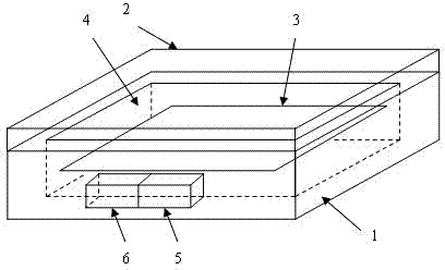
图1是本发明的结构示意图; Fig. 1 is a structural representation of the present invention;
图2是本发明电路部分结构示意图; Fig. 2 is a schematic diagram of the partial structure of the circuit of the present invention;
图3是本发明中系统控制模块的工作流程图; Fig. 3 is the work flowchart of system control module among the present invention;
图4是系统控制模块中的数据记录工作流程图; Fig. 4 is a flow chart of data recording work in the system control module;
图5是系统控制模块中与USB控制模块交互的工作流程图; Fig. 5 is the working flowchart of interacting with USB control module in system control module;
图6是本发明中的掉电检测与掉电过程中RAM数据保护的方法的工作示意图; Fig. 6 is the working schematic diagram of the method for RAM data protection in power-down detection and power-down process in the present invention;
图中,铝合金外壳1、铝合金上盖2、电路板3、灌封硅胶4、串行数据接口5、USB接口6。
In the figure, an aluminum alloy shell 1, an aluminum alloy
具体实施方式 Detailed ways
如图1所示,无人机飞行数据记录仪结构上主要由外壳封装与电路板3组成。外壳封装包括铝合金外壳1、铝合金上盖2、灌封硅胶4、串行数据接口5和USB接口6,电路板3固定在由铝合金外壳1和铝合金上盖2组成的内部空间,灌封硅胶4充满该内部空间并密封电路板3,电路板3与串行数据接口5及USB接口6相连。
As shown in FIG. 1 , the UAV flight data recorder is mainly composed of a casing package and a
铝合金外壳机械结构中,厚壁的铝合金外壳1和铝合金上盖2保证仪器在冲击、振动环境下的机械完整性;由铝合金外壳1和铝合金上盖2构成的完整屏蔽结构可以为内部电路提供优秀的电磁兼容性能。如图1所示,铝合金外壳1内安装电路板3,并充满灌封硅胶4,该灌封硅胶4可采用KENSEER 909型号双组份灌封硅胶,其具有一定弹性与阻尼,吸收无人机飞行、事故时的冲击与振动,保证内部电路结构的可靠性;该灌封胶将内部电路整体密封,提高其在潮湿、霉菌环境下的可靠性。
In the mechanical structure of the aluminum alloy casing, the thick-walled aluminum alloy casing 1 and the aluminum alloy
如图2所示,电路板3主要由串行接口电平转换模块、Flash存储模块、系统控制模块、供电监测模块、USB通讯模块和稳压模块组成。其中,串行接口电平转换模块、Flash存储模块、供电监测模块、USB通讯模块和稳压模块均与系统控制模块相连。串行接口电平转换模块与串行数据接口5相连,USB通讯模块与USB接口6相连。
As shown in FIG. 2 , the
下面详细描述各模块的工作过程。 The working process of each module is described in detail below.
串行接口电平转换模块将RS232或RS422接口电平转换为3.3V数字接口电平,当选用RS232接口电平时,该模块可由MAX3232芯片实现;当选用RS422接口电平时,该模块可以由MAX3490芯片实现。 The serial interface level conversion module converts the RS232 or RS422 interface level to 3.3V digital interface level. When the RS232 interface level is selected, the module can be realized by the MAX3232 chip; when the RS422 interface level is selected, the module can be realized by the MAX3490 chip accomplish.
Flash存储模块为系统提供足够大的存储容量,考虑到成本与可靠性,本发明中该模块选用1G字节SLC NAND Flash芯片实现。 The Flash storage module provides a large enough storage capacity for the system. In consideration of cost and reliability, the module is implemented with a 1G byte SLC NAND Flash chip in the present invention.
USB通讯模块实现与PC机的数据传输功能,如图5,其工作时使用USB终端接收来自PC机的指令,指令分为两种:数据传输指令与数据删除指令。当该模块接收到数据传输指令后,该模块通过与系统控制模块相连的8位数据线传输“读取Flash数据”指令,并以Slash FIFO模式打开USB终2的块传输接收模式,等待系统控制模块将数据传入USB终端。该模块可使用USB控制器CY7C68013实现。
The USB communication module realizes the data transmission function with the PC, as shown in Figure 5, when it works, it uses the USB terminal to receive instructions from the PC, and the instructions are divided into two types: data transmission instructions and data deletion instructions. When the module receives the data transmission command, the module transmits the "read Flash data" command through the 8-bit data line connected to the system control module, and opens the block transmission and reception mode of the
系统控制模块负责系统工作模式调度、NAND Flash控制、与USB通讯模块交互等功能,该控制模块可由FPGA芯片XC3S50AN实现。 The system control module is responsible for system work mode scheduling, NAND Flash control, interaction with USB communication module and other functions. This control module can be realized by FPGA chip XC3S50AN.
供电监测模块负责比较实际供电电压与额定工作电压的偏离,在实际供电电压过低时向系统控制模块发出掉电信号。该模块可由MAX811L实现,其通过监测系统电源输入端的电压,当该电压低于4.63V时,将给出系统掉电信号,此时系统内部的电容器内存储的电量仍能够位置系统工作100ms左右。系统控制模块的工作流程如图3所示: The power supply monitoring module is responsible for comparing the deviation between the actual power supply voltage and the rated working voltage, and sends a power-off signal to the system control module when the actual power supply voltage is too low. This module can be implemented by MAX811L, which monitors the voltage of the input terminal of the system power supply. When the voltage is lower than 4.63V, it will give a system power-off signal. At this time, the power stored in the capacitor inside the system can still work for about 100ms. The workflow of the system control module is shown in Figure 3:
当系统上电后,系统控制模块检测USB接口Vbus电压信号,若Vbus为0,那么认为USB接口没有连接至计算机,那么系统工作为数据记录状态;如果系统控制模块检测到Vbus信号,那么系统已经通过USB口连接至计算机,系统工作为数据传输或数据删除状态。当系统工作为数据传输或数据删除状态时,系统等待来自USB通讯模块的数据传输或数据删除指令,如果接收到数据删除指令,系统控制模块执行数据删除流程将Flash芯片内数据清除;如果接受到数据传输指令,系统控制模块执行Flash芯片读取流程,将Flash芯片内数据传入USB通讯模块。 After the system is powered on, the system control module detects the Vbus voltage signal of the USB interface. If the Vbus is 0, it is considered that the USB interface is not connected to the computer, and the system works as a data recording state; if the system control module detects the Vbus signal, the system has been Connect to the computer through the USB port, and the system works in the state of data transmission or data deletion. When the system is in the state of data transmission or data deletion, the system waits for the data transmission or data deletion command from the USB communication module. If the data deletion command is received, the system control module executes the data deletion process to clear the data in the Flash chip; Data transmission command, the system control module executes the process of reading the Flash chip, and transmits the data in the Flash chip to the USB communication module.
当系统控制模块工作在数据记录状态时,系统控制模块的数据记录工作流程如图4所示:系统控制模块首先扫描Flash芯片以寻找标号最小的空白块作为开始写入的地址。空白块的标记作用在Flash芯片每块的第0页备用区中,如果该块不是空白块,则该块的第0页备用区全为“0”;空白块的第0页备用区则全为“1”。如果上述过程未找到空白块,则表示系统存储空间已满,那么格式化第0块与第1块,并将第0块作为起始写入地址。系统控制模块能检测并读取串行接口数据,并将这些数据暂时存储在系统控制模块内部的SRAM中,当该SRAM中的数据达到4096字节时,系统控制模块一次性将这4096字节数据写入Flash芯片的一个空白页中;如果上述写入的空白页是该块中的最有一页,那么下一次写入地址块号跳转到下一个有效块中,下一次写入地址页号跳转到0。如果上述写入的空白页不是该块中的最有一页,那么下一次写入地址页号加1。Flash芯片的无效块在本飞行数据记录仪生产时扫描并写入FPGA程序中,并在跳转到下一个有效块号操作时进行判断,如果下一块号恰好是无效块,那么再跳转到下下块号作为下次写入地址。在系统控制模块工作正常,且Flash记录地址正常条件下,系统控制模块将通过串行接口向无人机的飞行控制计算机发送飞行数据记录仪状态帧。 When the system control module is working in the data recording state, the data recording workflow of the system control module is shown in Figure 4: the system control module first scans the Flash chip to find the blank block with the smallest label as the address to start writing. The mark of the blank block acts on the spare area of page 0 of each block of the Flash chip. If the block is not a blank block, the spare area of page 0 of the block is all "0"; the spare area of page 0 of the blank block is all "0". to "1". If the above process does not find a blank block, it means that the system storage space is full, then format the 0th block and the 1st block, and use the 0th block as the initial write address. The system control module can detect and read serial interface data, and temporarily store these data in the SRAM inside the system control module, when the data in the SRAM reaches 4096 bytes, the system control module will save the 4096 bytes Data is written into a blank page of the Flash chip; if the blank page written above is the last page in the block, then the next write address block number jumps to the next valid block, and the next write address page Number jumps to 0. If the blank page written above is not the last page in the block, add 1 to the next write address page number. The invalid block of the Flash chip is scanned and written into the FPGA program when the flight data recorder is produced, and judged when jumping to the next valid block number operation. If the next block number happens to be an invalid block, then jump to The next block number is used as the next write address. When the system control module works normally and the Flash record address is normal, the system control module will send the flight data recorder status frame to the flight control computer of the UAV through the serial interface.
考虑无人机的数据记录帧长度,串行接口的波特率设定在115200~256000比较合理。 Considering the data recording frame length of the UAV, it is more reasonable to set the baud rate of the serial interface at 115200~256000.
本发明的掉电检测与掉电时的RAM数据保护方法包含以下步骤,由图6所示: The RAM data protection method during power-down detection and power-down of the present invention comprises the following steps, as shown in Figure 6:
1、系统工作时,供电监测模块就开始实时将供电电压与内部参考基准电压4.63V进行比较,一旦发生供电电压低于内部参考电压4.63V时,供电监测模块即向系统控制模块发出系统掉电信号; 1. When the system is working, the power supply monitoring module will start to compare the power supply voltage with the internal reference voltage 4.63V in real time. Once the power supply voltage is lower than the internal reference voltage 4.63V, the power supply monitoring module will send a system power-off signal to the system control module. Signal;
2、在系统控制模块工作过程中,以1MHz频率进行掉电信号监测,一旦检测到掉电信号,即使内部SRAM中的接收数据未及4096字节,系统控制模也强制将内部SRAM数据写入Flash中,不足一页的由数据“0”补全; 2. During the working process of the system control module, the power-off signal is monitored at a frequency of 1MHz. Once the power-off signal is detected, even if the received data in the internal SRAM is less than 4096 bytes, the system control module will force the internal SRAM data to be written In Flash, less than one page is completed by data "0";
3、进行上述掉电数据保护操作后,系统控制模块停止操作Flash存储模块,并使能Flash存储模块的硬件写保护,以防在电压不足时对Flash芯片的擦除、写入操作损坏Flash内部数据; 3. After the above-mentioned power-down data protection operation is performed, the system control module stops operating the Flash storage module, and enables the hardware write protection of the Flash storage module, so as to prevent the Flash chip from being damaged by erasing and writing operations when the voltage is insufficient. data;
4、整个系统静态地等待系统内部电力耗尽; 4. The whole system waits statically for the internal power of the system to be exhausted;
5、在供电监测模块发出掉电信号后,如果系统供电恢复正常,供电监测模块向系统控制模块撤销掉电信号; 5. After the power supply monitoring module sends a power-down signal, if the system power supply returns to normal, the power supply monitoring module cancels the power-down signal to the system control module;
6、系统控制模块一旦发现掉电监测信号被撤销,则表示该掉电信号可能为供电系统不稳或外部强干扰导致,系统将继续正常记录数据。 6. Once the system control module finds that the power-off monitoring signal is cancelled, it means that the power-off signal may be caused by an unstable power supply system or strong external interference, and the system will continue to record data normally.
Claims (4)
Priority Applications (1)
| Application Number | Priority Date | Filing Date | Title |
|---|---|---|---|
| CN201310324156.0A CN103440211B (en) | 2013-07-28 | 2013-07-28 | Unmanned plane during flying datalogger and detection of power loss and RAM data guard method |
Applications Claiming Priority (1)
| Application Number | Priority Date | Filing Date | Title |
|---|---|---|---|
| CN201310324156.0A CN103440211B (en) | 2013-07-28 | 2013-07-28 | Unmanned plane during flying datalogger and detection of power loss and RAM data guard method |
Publications (2)
| Publication Number | Publication Date |
|---|---|
| CN103440211A true CN103440211A (en) | 2013-12-11 |
| CN103440211B CN103440211B (en) | 2016-04-20 |
Family
ID=49693902
Family Applications (1)
| Application Number | Title | Priority Date | Filing Date |
|---|---|---|---|
| CN201310324156.0A Expired - Fee Related CN103440211B (en) | 2013-07-28 | 2013-07-28 | Unmanned plane during flying datalogger and detection of power loss and RAM data guard method |
Country Status (1)
| Country | Link |
|---|---|
| CN (1) | CN103440211B (en) |
Cited By (22)
| Publication number | Priority date | Publication date | Assignee | Title |
|---|---|---|---|---|
| CN104391809A (en) * | 2014-11-28 | 2015-03-04 | 成都中远信电子科技有限公司 | Micro airborne data recording device |
| CN104391811A (en) * | 2014-11-28 | 2015-03-04 | 成都中远信电子科技有限公司 | A miniature airborne data recording device and its data recording and unloading method |
| CN105427406A (en) * | 2015-12-02 | 2016-03-23 | 北京七维航测科技股份有限公司 | Aeronautical data recording equipment |
| CN106062650A (en) * | 2014-09-30 | 2016-10-26 | 深圳市大疆创新科技有限公司 | System and method for data recording and analysis |
| CN106354429A (en) * | 2016-08-26 | 2017-01-25 | 杨百川 | Data storage module for UAV flight control system and storage method thereof |
| CN106373216A (en) * | 2016-08-29 | 2017-02-01 | 上海航盛实业有限公司 | Vehicular video monitoring terminal |
| CN106468911A (en) * | 2015-08-20 | 2017-03-01 | 陕西千山航空电子有限责任公司 | A kind of fault message backup method for fault diagnosis |
| CN106605180A (en) * | 2015-03-31 | 2017-04-26 | 深圳市大疆创新科技有限公司 | System and method for monitoring flight |
| CN107197380A (en) * | 2017-01-26 | 2017-09-22 | 青岛海信电器股份有限公司 | Intelligent television and its under-voltage protection fault-tolerance approach |
| CN108052289A (en) * | 2017-12-12 | 2018-05-18 | 深圳市创维软件有限公司 | Method, set-top box and the storage medium of data processing |
| CN109279041A (en) * | 2018-11-29 | 2019-01-29 | 山东宇航航空科技有限公司 | A kind of multi-functional unmanned plane during flying platform |
| CN109597402A (en) * | 2018-12-07 | 2019-04-09 | 中国航发南方工业有限公司 | The data storage and management device and engine of engine |
| CN109616150A (en) * | 2018-12-07 | 2019-04-12 | 中国航发南方工业有限公司 | The data storage and management device and its power-off protection method of engine |
| CN109741485A (en) * | 2018-12-26 | 2019-05-10 | 西安现代控制技术研究所 | An aircraft data recorder |
| CN110832737A (en) * | 2018-11-30 | 2020-02-21 | 深圳市大疆创新科技有限公司 | Control method, drone, and computer-readable storage medium |
| CN111163116A (en) * | 2020-04-08 | 2020-05-15 | 成都新动力软件有限公司 | A device for extracting network data parameters of large traffic |
| CN113687710A (en) * | 2021-10-26 | 2021-11-23 | 西安羚控电子科技有限公司 | Power failure processing method and system for flight control management computer of fixed-wing unmanned aerial vehicle |
| CN114051318A (en) * | 2021-11-15 | 2022-02-15 | 四川航天烽火伺服控制技术有限公司 | Steering engine, ultralow-temperature steering engine controller and small-space asymmetric PCB structure thereof |
| CN114117546A (en) * | 2021-11-08 | 2022-03-01 | 陕西千山航空电子有限责任公司 | Integrity test verification method for flying parameter data of throwing recorder |
| CN115469802A (en) * | 2022-08-31 | 2022-12-13 | 北京奕斯伟计算技术股份有限公司 | data storage device |
| CN116124189A (en) * | 2023-02-06 | 2023-05-16 | 湖南艾科诺维科技有限公司 | Recorder with overload impact resistance and preparation method thereof |
| CN116301601A (en) * | 2023-02-16 | 2023-06-23 | 上海东软载波微电子有限公司 | Embedded system built-in Flash emulation EEPROM data storage method and device |
Citations (2)
| Publication number | Priority date | Publication date | Assignee | Title |
|---|---|---|---|---|
| CN201820275U (en) * | 2010-10-29 | 2011-05-04 | 浙江大学 | Manufacturing recording instrument |
| CN102074055A (en) * | 2011-01-04 | 2011-05-25 | 浙江大学 | Multi-machine collaboration framework based fast recorder and self-calibration and multi-machine collaboration method |
-
2013
- 2013-07-28 CN CN201310324156.0A patent/CN103440211B/en not_active Expired - Fee Related
Patent Citations (2)
| Publication number | Priority date | Publication date | Assignee | Title |
|---|---|---|---|---|
| CN201820275U (en) * | 2010-10-29 | 2011-05-04 | 浙江大学 | Manufacturing recording instrument |
| CN102074055A (en) * | 2011-01-04 | 2011-05-25 | 浙江大学 | Multi-machine collaboration framework based fast recorder and self-calibration and multi-machine collaboration method |
Non-Patent Citations (2)
| Title |
|---|
| 张波等: "低成本无人机机载记录仪设计与应用", 《航空计算技术》 * |
| 韩勇豪: "一种大容量无人机飞行数据记录仪的研制", 《国优秀硕士学位论文全文数据库》 * |
Cited By (35)
| Publication number | Priority date | Publication date | Assignee | Title |
|---|---|---|---|---|
| CN106062650B (en) * | 2014-09-30 | 2020-12-22 | 深圳市大疆创新科技有限公司 | System and method for data recording and analysis |
| US9652904B2 (en) | 2014-09-30 | 2017-05-16 | SZ DJI Technology Co., Ltd. | System and method for data recording and analysis |
| US10580230B2 (en) | 2014-09-30 | 2020-03-03 | SZ DJI Technology Co., Ltd. | System and method for data recording and analysis |
| CN106062650A (en) * | 2014-09-30 | 2016-10-26 | 深圳市大疆创新科技有限公司 | System and method for data recording and analysis |
| US9905060B2 (en) | 2014-09-30 | 2018-02-27 | SZ DJI Technology Co., Ltd. | System and method for data recording and analysis |
| US11205311B2 (en) | 2014-09-30 | 2021-12-21 | SZ DJI Technology Co., Ltd. | System and method for data recording and analysis |
| CN104391809A (en) * | 2014-11-28 | 2015-03-04 | 成都中远信电子科技有限公司 | Micro airborne data recording device |
| CN104391811A (en) * | 2014-11-28 | 2015-03-04 | 成都中远信电子科技有限公司 | A miniature airborne data recording device and its data recording and unloading method |
| CN106605180A (en) * | 2015-03-31 | 2017-04-26 | 深圳市大疆创新科技有限公司 | System and method for monitoring flight |
| US10692311B2 (en) | 2015-03-31 | 2020-06-23 | SZ DJI Technology Co., Ltd. | Systems and methods for monitoring flight |
| CN106468911A (en) * | 2015-08-20 | 2017-03-01 | 陕西千山航空电子有限责任公司 | A kind of fault message backup method for fault diagnosis |
| CN105427406B (en) * | 2015-12-02 | 2018-04-17 | 北京七维航测科技股份有限公司 | Aeronautical data recording equipment |
| CN105427406A (en) * | 2015-12-02 | 2016-03-23 | 北京七维航测科技股份有限公司 | Aeronautical data recording equipment |
| CN106354429A (en) * | 2016-08-26 | 2017-01-25 | 杨百川 | Data storage module for UAV flight control system and storage method thereof |
| CN106373216A (en) * | 2016-08-29 | 2017-02-01 | 上海航盛实业有限公司 | Vehicular video monitoring terminal |
| CN107197380B (en) * | 2017-01-26 | 2019-12-06 | 青岛海信电器股份有限公司 | Intelligent television and undervoltage protection fault-tolerant method thereof |
| CN107197380A (en) * | 2017-01-26 | 2017-09-22 | 青岛海信电器股份有限公司 | Intelligent television and its under-voltage protection fault-tolerance approach |
| CN108052289A (en) * | 2017-12-12 | 2018-05-18 | 深圳市创维软件有限公司 | Method, set-top box and the storage medium of data processing |
| CN109279041A (en) * | 2018-11-29 | 2019-01-29 | 山东宇航航空科技有限公司 | A kind of multi-functional unmanned plane during flying platform |
| CN109279041B (en) * | 2018-11-29 | 2024-05-31 | 山东宇航航空科技有限公司 | Multifunctional unmanned aerial vehicle flight platform |
| CN110832737A (en) * | 2018-11-30 | 2020-02-21 | 深圳市大疆创新科技有限公司 | Control method, drone, and computer-readable storage medium |
| CN109597402A (en) * | 2018-12-07 | 2019-04-09 | 中国航发南方工业有限公司 | The data storage and management device and engine of engine |
| CN109616150A (en) * | 2018-12-07 | 2019-04-12 | 中国航发南方工业有限公司 | The data storage and management device and its power-off protection method of engine |
| CN109597402B (en) * | 2018-12-07 | 2020-11-27 | 中国航发南方工业有限公司 | Data storage and management device of engine and engine |
| CN109741485A (en) * | 2018-12-26 | 2019-05-10 | 西安现代控制技术研究所 | An aircraft data recorder |
| CN111163116A (en) * | 2020-04-08 | 2020-05-15 | 成都新动力软件有限公司 | A device for extracting network data parameters of large traffic |
| CN111163116B (en) * | 2020-04-08 | 2020-07-10 | 成都新动力软件有限公司 | A device for extracting network data parameters of large traffic |
| CN113687710A (en) * | 2021-10-26 | 2021-11-23 | 西安羚控电子科技有限公司 | Power failure processing method and system for flight control management computer of fixed-wing unmanned aerial vehicle |
| CN113687710B (en) * | 2021-10-26 | 2022-03-22 | 西安羚控电子科技有限公司 | Power failure processing method and system for flight control management computer of fixed-wing unmanned aerial vehicle |
| CN114117546A (en) * | 2021-11-08 | 2022-03-01 | 陕西千山航空电子有限责任公司 | Integrity test verification method for flying parameter data of throwing recorder |
| CN114117546B (en) * | 2021-11-08 | 2025-01-10 | 陕西千山航空电子有限责任公司 | A method for integrity testing and verification of flight parameter data of a jettisonable recorder |
| CN114051318A (en) * | 2021-11-15 | 2022-02-15 | 四川航天烽火伺服控制技术有限公司 | Steering engine, ultralow-temperature steering engine controller and small-space asymmetric PCB structure thereof |
| CN115469802A (en) * | 2022-08-31 | 2022-12-13 | 北京奕斯伟计算技术股份有限公司 | data storage device |
| CN116124189A (en) * | 2023-02-06 | 2023-05-16 | 湖南艾科诺维科技有限公司 | Recorder with overload impact resistance and preparation method thereof |
| CN116301601A (en) * | 2023-02-16 | 2023-06-23 | 上海东软载波微电子有限公司 | Embedded system built-in Flash emulation EEPROM data storage method and device |
Also Published As
| Publication number | Publication date |
|---|---|
| CN103440211B (en) | 2016-04-20 |
Similar Documents
| Publication | Publication Date | Title |
|---|---|---|
| CN103440211B (en) | Unmanned plane during flying datalogger and detection of power loss and RAM data guard method | |
| CN102449610B (en) | Method and device for providing release management of storage system logical block addresses | |
| CN104951395A (en) | Debugging information processing method and device for embedded system | |
| CN103625647B (en) | A kind of airborne integrated data loads transmitting device | |
| CN112530475B (en) | Mechanical hard disk shockproof device, method and system, electronic equipment and storage medium | |
| CN103246280A (en) | Electric automobile diagnostic system | |
| CN103632411A (en) | Storage method and device for vehicle-carried data | |
| CN114636875A (en) | Fault recording method and device, storage medium and energy storage converter | |
| CN202414169U (en) | Configurable universal comprehensive avionics system | |
| CN201910080U (en) | Dynamic data collecting system of railway train | |
| CN111199142A (en) | QAR data processing method, device and system | |
| CN107168919A (en) | A kind of missile-borne platform data acquisition and memory system and method | |
| CN103617008B (en) | Double SD card multimedia file storage system of Vehicular video monitoring terminal and method | |
| CN116776398A (en) | Data recording system with self-destruction function | |
| CN103679850A (en) | Bus recorder | |
| CN103106160A (en) | Airborne environment serial advanced technology attachment (STAT) bus storage control system and control method thereof | |
| CN103136160A (en) | Cache continue transmission method and system for data transmission discontinuity points among railway vehicle devices | |
| CN103259998A (en) | Recording system and method for aerial survey image data | |
| US20170160961A1 (en) | Memory management method, memory control circuit unit, and memory storage apparatus | |
| CN105427406B (en) | Aeronautical data recording equipment | |
| CN106815126B (en) | General file system log recording method and device | |
| CN205388780U (en) | Machine carries data record appearance | |
| CN108132871B (en) | Airborne computer interface fault recording method | |
| CN114443339B (en) | Error logging method based on double timestamp circular queue | |
| CN111638886B (en) | Remote storage unloading equipment based on Fiber Channel |
Legal Events
| Date | Code | Title | Description |
|---|---|---|---|
| C06 | Publication | ||
| PB01 | Publication | ||
| C10 | Entry into substantive examination | ||
| SE01 | Entry into force of request for substantive examination | ||
| C14 | Grant of patent or utility model | ||
| GR01 | Patent grant | ||
| CF01 | Termination of patent right due to non-payment of annual fee |
Granted publication date: 20160420 |
|
| CF01 | Termination of patent right due to non-payment of annual fee |