CN103375831A - Range hood and rotary air curtain generation device for oil smoke purification device - Google Patents
Range hood and rotary air curtain generation device for oil smoke purification device Download PDFInfo
- Publication number
- CN103375831A CN103375831A CN 201210122092 CN201210122092A CN103375831A CN 103375831 A CN103375831 A CN 103375831A CN 201210122092 CN201210122092 CN 201210122092 CN 201210122092 A CN201210122092 A CN 201210122092A CN 103375831 A CN103375831 A CN 103375831A
- Authority
- CN
- China
- Prior art keywords
- oil smoke
- wind screen
- rotary wind
- generation device
- screen generation
- Prior art date
- Legal status (The legal status is an assumption and is not a legal conclusion. Google has not performed a legal analysis and makes no representation as to the accuracy of the status listed.)
- Pending
Links
- 239000000779 smoke Substances 0.000 title claims abstract description 139
- 238000000746 purification Methods 0.000 title abstract 3
- 239000003517 fume Substances 0.000 claims description 18
- 230000000694 effects Effects 0.000 description 12
- 238000010586 diagram Methods 0.000 description 6
- 238000010521 absorption reaction Methods 0.000 description 4
- 230000004888 barrier function Effects 0.000 description 3
- 238000010411 cooking Methods 0.000 description 3
- 230000004048 modification Effects 0.000 description 2
- 238000012986 modification Methods 0.000 description 2
- 230000009286 beneficial effect Effects 0.000 description 1
- 239000007789 gas Substances 0.000 description 1
- 238000004519 manufacturing process Methods 0.000 description 1
- 238000000034 method Methods 0.000 description 1
Images


Classifications
-
- F—MECHANICAL ENGINEERING; LIGHTING; HEATING; WEAPONS; BLASTING
- F24—HEATING; RANGES; VENTILATING
- F24C—DOMESTIC STOVES OR RANGES ; DETAILS OF DOMESTIC STOVES OR RANGES, OF GENERAL APPLICATION
- F24C15/00—Details
- F24C15/20—Removing cooking fumes
-
- F—MECHANICAL ENGINEERING; LIGHTING; HEATING; WEAPONS; BLASTING
- F24—HEATING; RANGES; VENTILATING
- F24C—DOMESTIC STOVES OR RANGES ; DETAILS OF DOMESTIC STOVES OR RANGES, OF GENERAL APPLICATION
- F24C15/00—Details
- F24C15/20—Removing cooking fumes
- F24C15/2028—Removing cooking fumes using an air curtain
Landscapes
- Engineering & Computer Science (AREA)
- Chemical & Material Sciences (AREA)
- Combustion & Propulsion (AREA)
- Mechanical Engineering (AREA)
- General Engineering & Computer Science (AREA)
- Ventilation (AREA)
- Structures Of Non-Positive Displacement Pumps (AREA)
- Separating Particles In Gases By Inertia (AREA)
Abstract
The invention provides a rotary air curtain generation device for an oil smoke purification device. The rotary air curtain generation device is used for generating a rotary air curtain encircling an oil smoke path and/or an oil smoke source. Therefore, on one hand, in the presence of the air curtain, escaping of oil smoke can be remarkably reduced; on the other hand, the air curtain is rotary, so that the suction for oil smoke of the oil smoke purification device can be improved.
Description
[technical field]
The present invention relates to the fume purifying field, relate in particular to smoke exhaust ventilator.
[background technology]
Range hood claims again smoke exhaust ventilator, is a kind of kitchen appliance that purifies kitchen environment.It is installed in the top of cooking stove in the kitchen, the harmful oil smoke that produces in the refuse of cooking stove burning and the cooking process can be taken away rapidly, discharges outdoorly, and the minimizing indoor pollution purifies the air of a room, and gas defence, explosion-proof safety guarantee effect are arranged.
How to reduce fumes escaping, and then promote oil smoke absorption effect, all be the wide concerned technical barrier in this area all the time, and it directly concerns the smoke exhaust ventilator competitiveness of product in market.For above-mentioned technical barrier, various solutions have appearred in the prior art: as, install the curtain that stops fumes escaping additional; For another example, improve blower fan system power etc.But these existing solutions or effect are undesirable, or can bring the new problems such as noise strengthens, power consumption increase, all can't solve preferably above-mentioned technical barrier.
Unless sufficient evidence support is arranged, otherwise prior art described here and do not mean that and admit that these prior aries those of ordinary skill for the field that the invention relates to before the application's the applying date is known.
[summary of the invention]
Main purpose of the present invention is to propose a kind ofly can significantly reduce fumes escaping, and then promotes the smoke exhaust ventilator technical solution that oil smoke is absorbed effect.
Particularly, the present invention proposes a kind of rotary wind screen generation device for fume purifier of fume, and described rotary wind screen generation device is for generation of the rotary wind screen that surrounds oil smoke path and/or oil smoke source.Like this, on the one hand, because the existence of air curtain can significantly reduce fumes escaping; On the other hand, because air curtain rotates, it also helps to promote fume purifier of fume to the suction of oil smoke.
Optionally, this rotary wind screen generation device comprises the housing of drive division and hollow; Described housing comprises the outlet of oil smoke entrance and oil smoke, surrounds on the edge of described oil smoke entrance and is provided with blade; Described drive division is used for driving described housing rotary, and then drives described blade and produce described rotary wind screen.Such rotary wind screen generation device, low cost of manufacture, and the rotary wind screen that produces is effective.
Optionally, the edge that surrounds described oil smoke entrance is annular, and the diameter of the cylindrical of this annulus is b; 80mm≤b≤480mm.Find through a large amount of tests, when adopting this technical characterictic, can obtain better result of use.
Optionally, the edge that surrounds described oil smoke outlet is annular, and the diameter of the cylindrical of this annulus is a; 50mm≤a≤200mm.Find through a large amount of tests, when adopting this technical characterictic, can obtain better result of use.
Optionally, the area of described oil smoke entrance is greater than the area of described oil smoke outlet.Find through a large amount of tests, when adopting this technical characterictic, can obtain better result of use.
Optionally, the area of described oil smoke entrance is 1.618 times of area of described oil smoke outlet.Find through a large amount of tests, when the corresponding relation of the area of the area of described oil smoke entrance and the outlet of described oil smoke adopts this technical characterictic, can obtain splendid result of use.
Optionally, the quantity of described blade is at least two; Described each blade is obliquely installed equably on the edge that surrounds described oil smoke entrance, and described each blade is all horizontal by the α angle.Find through a large amount of tests, when adopting this technical characterictic, can obtain better result of use.
Optionally, 15 °≤α≤85 °.Find through a large amount of tests, when the corresponding relation of the area of the area of described oil smoke entrance and the outlet of described oil smoke adopts this technical characterictic, can obtain splendid result of use.
Optionally, described rotary wind screen integral body is truncated cone-shaped.Find through a large amount of tests, when adopting this technical characterictic, can obtain better result of use.
Optionally, the projecting direction of described rotary wind screen is opposite with the flow direction of oil smoke.Like this, can produce the cyclone effect, namely oil smoke flows to described fume purifier of fume with the form of cyclone.
The present invention also proposes a kind of smoke exhaust ventilator, and it is provided with such as above each described rotary wind screen generation device.Like this, on the one hand, because the existence of air curtain can significantly reduce fumes escaping; On the other hand, because air curtain rotates, it also helps to promote smoke exhaust ventilator to the suction of oil smoke.
Optionally, described smoke exhaust ventilator is provided with blast pipe; Described oil smoke outlet is connected with described blast pipe; Described blast pipe is connected with negative pressure generating device.
Optionally, described smoke exhaust ventilator is provided with motor and impeller; Described motor also is used for driving described housing rotary.That is, this motor is described drive division.
Optionally, described impeller is the multiple wing type centrifugal impeller; Described oil smoke outlet is connected in the air inlet place of described multiple wing type centrifugal impeller.Like this, under the acting in conjunction of described rotary wind screen generation device and multiple wing type centrifugal impeller, can produce the cyclone effect, namely oil smoke flows to described fume purifier of fume with the form of cyclone.
Optionally, the wind speed that produces of described multiple wing type centrifugal impeller is 1.5 to 3 times of the wind speed that produces of described rotary wind screen generation device.Find through a large amount of tests, when adopting this technical characterictic, can obtain better result of use.
Foregoing invention content of the present invention is not be used to describing all possible embodiments of the present invention.In the whole application, many places provide guidance by enumerating example, and these examples can be used for various feasible combinations.
[description of drawings]
The following drawings is only done the present invention and is schematically illustrated and explain, not delimit the scope of the invention, wherein:
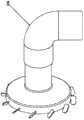
Fig. 1 is the structural representation of rotary wind screen generation device embodiment 1 of the present invention;
Fig. 2 is another structural representation of rotary wind screen generation device embodiment 1 of the present invention;
Fig. 3 is the cutaway view along B-B line among Fig. 2;
Fig. 4 is the application state schematic diagram of rotary wind screen generation device embodiment 1 of the present invention;
Fig. 5 is the cutaway view of structure shown in Figure 4;
Fig. 6 is the application state schematic diagram of rotary wind screen generation device embodiment 2 of the present invention;
Fig. 7 is the another application state schematic diagram of rotary wind screen generation device embodiment 2 of the present invention;
Fig. 8 is the again application state schematic diagram of rotary wind screen generation device embodiment 2 of the present invention;
Fig. 9 is the cutaway view along A-A line among Fig. 8;
Figure 10 is the application state schematic diagram of rotary wind screen generation device embodiment 3 of the present invention;
Figure 11 is the another application state schematic diagram of rotary wind screen generation device embodiment 3 of the present invention;
Figure 12 is the cutaway view along B-B line among Figure 11.
Explanation about Reference numeral among the figure:
1-rotary wind screen generation device, 2-housing, 3-oil smoke entrance, the outlet of 4-oil smoke, 5-blade, 6-blast pipe, 7-impeller.
[specific embodiment]
For making purpose of the present invention, scheme and beneficial effect more cheer and bright, the invention will be further described below in conjunction with accompanying drawing and preferred embodiment.What at first need to be explained is that in the specific descriptions to preferred embodiment, identical or similar feature has identical Reference numeral below.In addition, indivedual accompanying drawings may be accurate not, in such cases, should be as the criterion with text description.
Embodiment 1
The first that the present invention proposes is used for rotary wind screen generation device 1 embodiment of smoke exhaust ventilator, shown in Fig. 1 to 5.This rotary wind screen generation device 1 comprises the housing 2 of hollow, and this housing 2 comprises oil smoke entrance 3 and oil smoke outlet 4.Surround on the edge of oil smoke entrance 3 and evenly be provided with 12 blades 5.The shape of each blade 5 is identical, all in the form of sheets.Each blade 5 all is obliquely installed on the edge that surrounds oil smoke entrance 3, and each blade 5 is all horizontal by the α angle, α=60 °.The edge that surrounds oil smoke entrance 3 is annular, and the diameter of the cylindrical of this annulus is b=330mm.The edge that surrounds oil smoke outlet 4 also is annular, and the diameter of the cylindrical of this annulus is a=120mm.
This rotary wind screen generation device 1 also is provided with the drive division (not shown), is used for driving housing 2 rotations.Housing 2 rotates, and then produces the rotary wind screen that surrounds oil smoke paths and oil smoke source with moving vane 5." oil smoke path ", refer to oil smoke from the oil smoke source and course path to smoke exhaust ventilator.The projecting direction of rotary wind screen opposite with the flow direction of oil smoke (unintelligible is opposite accurately on the mathematical meaning, but opposite on the general direction).The flow direction of oil smoke, refer to oil smoke from the oil smoke source and course direction to smoke exhaust ventilator." projecting direction of rotary wind screen " refers to the direction from the end of blade 5 these rotary wind screens of sensing.Rotary wind screen integral body is truncated cone-shaped, and blade 5 places are corresponding to the upper bottom surface of this round platform.Need to be pointed out that why be referred to as " rotary wind screen ", be because consist of the air-flow of air curtain, except the projecting direction at air curtain moves, upwards also moves in the week of air curtain." circumferentially ", refer to the direction around the axis of described round platform.
Shown in Figure 4 and 5, this smoke exhaust ventilator is provided with blast pipe 6.The oil smoke of rotary wind screen generation device 1 outlet 4 be connected with blast pipe 6 (belong to and being flexibly connected, when housing 2 rotates, blast pipe 6 transfixions).In addition, blast pipe 6 also is connected with negative pressure generating device.Negative pressure generating device is used in blast pipe 6 interior generation negative pressure, and then makes oil smoke from the oil smoke source and course to blast pipe 6.Particularly, negative pressure generating device can be blower fan, such as axial flow blower or centrifugal blower; Negative pressure generating device can also be that other can be applied to the existing device that can produce negative pressure in the present embodiment.Acting in conjunction just because of negative pressure generating device and rotary wind screen generation device 1 can produce the cyclone effect, and namely oil smoke flows to blast pipe 6 with the form of cyclone, and then significantly promotes oil smoke absorption effect.
Below only be the preferred embodiments of the present invention, some technical characterictic is made amendment or replaced the embodiment that can also obtain other.As, blade also can adopt other the feasible shapes except sheet.For another example, the projecting direction of rotary wind screen is identical with the flow direction of oil smoke also to be feasible, and just in this case, concrete structure and the present embodiment of rotary wind screen generation device are different.
The second that the present invention proposes is used for rotary wind screen generation device 1 embodiment of smoke exhaust ventilator, shown in Fig. 6 to 9.This rotary wind screen generation device 1 comprises the housing 2 of hollow, and this housing 2 comprises oil smoke entrance 3 and oil smoke outlet 4.Surround on the edge of oil smoke entrance 3 and evenly be provided with ten blades 5.The shape of each blade 5 is identical, all in the form of sheets.Each blade 5 all is obliquely installed on the edge that surrounds oil smoke entrance 3, and each blade 5 is all horizontal by the α angle, α=45 °.The edge that surrounds oil smoke entrance 3 is annular, and the diameter of the cylindrical of this annulus is b=242.7mm.The edge that surrounds oil smoke outlet 4 also is annular, and the diameter of the cylindrical of this annulus is a=150mm.
This smoke exhaust ventilator is provided with motor and multiple wing type centrifugal impeller 7.The oil smoke of housing 2 exports 4 places and is provided with flange portion, and this flange portion is connected by screw the air inlet place that is arranged at multiple wing type centrifugal impeller 7, as shown in Figure 6.Described motor is used for driving this multiple wing type centrifugal impeller 7 rotations, and then drives housing 2 rotations.7 rotations of multiple wing type centrifugal impeller produce negative pressure, and then make oil smoke from the oil smoke source and course to this multiple wing type centrifugal impeller 7.Housing 2 rotates, and then produces the rotary wind screen that surrounds oil smoke paths and oil smoke source with moving vane 5." oil smoke path ", refer to oil smoke from the oil smoke source and course path to smoke exhaust ventilator.The projecting direction of rotary wind screen opposite with the flow direction of oil smoke (unintelligible is opposite accurately on the mathematical meaning, but opposite on the general direction).The flow direction of oil smoke, refer to oil smoke from the oil smoke source and course direction to smoke exhaust ventilator." projecting direction of rotary wind screen " refers to the direction from the end of blade 5 these rotary wind screens of sensing.Rotary wind screen integral body is truncated cone-shaped, and blade 5 places are corresponding to the upper bottom surface of this round platform.Need to be pointed out that why be referred to as " rotary wind screen ", be because consist of the air-flow of air curtain, except the projecting direction at air curtain moves, upwards also moves in the week of air curtain." circumferentially ", refer to the direction around the axis of described round platform.Acting in conjunction just because of multiple wing type centrifugal impeller 7 and rotary wind screen generation device 1 can produce the cyclone effect, and namely oil smoke flows to blast pipe 6 with the form of cyclone, and then significantly promotes oil smoke absorption effect.
With regard to present embodiment, the wind speed that multiple wing type centrifugal impeller 7 produces is 2.5 times of the wind speed that produces of described rotary wind screen generation device 1.
The third rotary wind screen generation device 1 embodiment for smoke exhaust ventilator that the present invention proposes is shown in Figure 10 to 12.This rotary wind screen generation device 1 comprises the housing 2 of hollow, and this housing 2 comprises oil smoke entrance 3 and oil smoke outlet 4.Surround on the edge of oil smoke entrance 3 and evenly be provided with 12 blades 5.The shape of each blade 5 is identical, all in the form of sheets.Each blade 5 all is obliquely installed on the edge that surrounds oil smoke entrance 3, and each blade 5 is all horizontal by the α angle, α=75 °.The edge that surrounds oil smoke entrance 3 is annular, and the diameter of the cylindrical of this annulus is b=450mm.The edge that surrounds oil smoke outlet 4 also is annular, and the diameter of the cylindrical of this annulus is a=180mm.
This smoke exhaust ventilator is provided with motor and impeller 7.The oil smoke outlet 4 of housing 2 is connected in the air inlet place of impeller 7.Motor is used for impeller 7 rotations, and then drives housing 2 rotations.Impeller 7 rotations produce negative pressure, and then make oil smoke from the oil smoke source and course to this impeller 7.Housing 2 rotates, and then produces the rotary wind screen that surrounds oil smoke paths and oil smoke source with moving vane 5." oil smoke path ", refer to oil smoke from the oil smoke source and course path to smoke exhaust ventilator.The projecting direction of rotary wind screen opposite with the flow direction of oil smoke (unintelligible is opposite accurately on the mathematical meaning, but opposite on the general direction).The flow direction of oil smoke, refer to oil smoke from the oil smoke source and course direction to smoke exhaust ventilator." projecting direction of rotary wind screen " refers to the direction from the end of blade 5 these rotary wind screens of sensing.Rotary wind screen integral body is truncated cone-shaped, and blade 5 places are corresponding to the upper bottom surface of this round platform.Need to be pointed out that why be referred to as " rotary wind screen ", be because consist of the air-flow of air curtain, except the projecting direction at air curtain moves, upwards also moves in the week of air curtain." circumferentially ", refer to the direction around the axis of described round platform.Acting in conjunction just because of impeller 7 and rotary wind screen generation device 1 can produce the cyclone effect, and namely oil smoke flows to blast pipe 6 with the form of cyclone, and then significantly promotes oil smoke absorption effect.
Need annotatedly to be, the present invention should not be understood to only limit to embodiment described above, but should be understood to cover claim of the present invention in conjunction with the specification disclosure definite all possible performance.Therefore, every content that does not break away from technical solution of the present invention to any simple modification, equivalent variations and modification that above embodiment does, all belongs to the protection domain of technical solution of the present invention according to technical spirit of the present invention.Special needs to be pointed out is, based on any bad application that changes of the present invention, still belong to the protection domain of technical solution of the present invention.
Claims (15)
1. rotary wind screen generation device (1) that is used for fume purifier of fume is characterized in that:
Described rotary wind screen generation device (1) is for generation of the rotary wind screen that surrounds oil smoke path and/or oil smoke source.
2. rotary wind screen generation device according to claim 1 (1) is characterized in that:
This rotary wind screen generation device (1) comprises the housing (2) of drive division and hollow;
Described housing (2) comprises oil smoke entrance (3) and oil smoke outlet (4), surrounds on the edge of described oil smoke entrance (3) and is provided with blade (5);
Described drive division is used for driving described housing (2) rotation, and then drives described blade (5) and produce described rotary wind screen.
3. rotary wind screen generation device according to claim 2 (1) is characterized in that:
The edge that surrounds described oil smoke entrance (3) is annular, and the diameter of the cylindrical of this annulus is b;
80mm≤b≤480mm。
4. rotary wind screen generation device according to claim 3 (1) is characterized in that:
The edge that surrounds described oil smoke outlet (4) is annular, and the diameter of the cylindrical of this annulus is a;
50mm≤a≤200mm。
5. rotary wind screen generation device according to claim 2 (1) is characterized in that:
The area of described oil smoke entrance (3) exports the area of (4) greater than described oil smoke.
6. rotary wind screen generation device according to claim 5 (1) is characterized in that:
The area of described oil smoke entrance (3) is 1.618 times of area of described oil smoke outlet (4).
7. rotary wind screen generation device according to claim 2 (1) is characterized in that:
The quantity of described blade (5) is at least two;
Described each blade (5) is obliquely installed equably on the edge that surrounds described oil smoke entrance (3), and described each blade (5) is all horizontal by the α angle.
8. rotary wind screen generation device according to claim 7 (1) is characterized in that:
15°≤α≤85°。
9. rotary wind screen generation device according to claim 1 (1) is characterized in that:
Described rotary wind screen integral body is truncated cone-shaped.
10. rotary wind screen generation device according to claim 1 (1) is characterized in that:
The projecting direction of described rotary wind screen is opposite with the flow direction of oil smoke.
11. a smoke exhaust ventilator, it is provided with such as the described rotary wind screen generation device of above each claim (1).
12. smoke exhaust ventilator according to claim 11 is characterized in that:
Described smoke exhaust ventilator is provided with blast pipe (6);
Described oil smoke outlet (4) is connected with described blast pipe (6);
Described blast pipe (6) is connected with negative pressure generating device.
13. smoke exhaust ventilator according to claim 11 is characterized in that:
Described smoke exhaust ventilator is provided with motor and impeller (7);
Described motor also is used for driving described housing (2) rotation.
14. smoke exhaust ventilator according to claim 13 is characterized in that:
Described impeller (7) is multiple wing type centrifugal impeller (7);
Described oil smoke outlet (4) is connected in the air inlet place of described multiple wing type centrifugal impeller (7).
15. smoke exhaust ventilator according to claim 14 is characterized in that:
The wind speed that described multiple wing type centrifugal impeller (7) produces is 1.5 to 3 times of the wind speed that produces of described rotary wind screen generation device (1).
Priority Applications (3)
| Application Number | Priority Date | Filing Date | Title |
|---|---|---|---|
| CN 201210122092 CN103375831A (en) | 2012-04-20 | 2012-04-20 | Range hood and rotary air curtain generation device for oil smoke purification device |
| EP13720276.8A EP2839217A1 (en) | 2012-04-20 | 2013-04-11 | Rotary air curtain generating device used in a fume purification device, and range hood comprising such device |
| PCT/EP2013/057525 WO2013156372A1 (en) | 2012-04-20 | 2013-04-11 | Rotary air curtain generating device used in a fume purification device, and range hood comprising such device |
Applications Claiming Priority (1)
| Application Number | Priority Date | Filing Date | Title |
|---|---|---|---|
| CN 201210122092 CN103375831A (en) | 2012-04-20 | 2012-04-20 | Range hood and rotary air curtain generation device for oil smoke purification device |
Publications (1)
| Publication Number | Publication Date |
|---|---|
| CN103375831A true CN103375831A (en) | 2013-10-30 |
Family
ID=48289058
Family Applications (1)
| Application Number | Title | Priority Date | Filing Date |
|---|---|---|---|
| CN 201210122092 Pending CN103375831A (en) | 2012-04-20 | 2012-04-20 | Range hood and rotary air curtain generation device for oil smoke purification device |
Country Status (3)
| Country | Link |
|---|---|
| EP (1) | EP2839217A1 (en) |
| CN (1) | CN103375831A (en) |
| WO (1) | WO2013156372A1 (en) |
Cited By (5)
| Publication number | Priority date | Publication date | Assignee | Title |
|---|---|---|---|---|
| CN105465850A (en) * | 2014-06-13 | 2016-04-06 | 博西华电器(江苏)有限公司 | Oil fume exhaust ventilator |
| CN105972662A (en) * | 2016-06-29 | 2016-09-28 | 广东万和新电气股份有限公司 | Rotary flow guiding devices and range hood using the same |
| CN107421050A (en) * | 2017-07-21 | 2017-12-01 | 艾宴清 | Penetration type slows down gas phase diffusion equipment |
| CN110779062A (en) * | 2019-11-14 | 2020-02-11 | 珠海格力电器股份有限公司 | Air conditioner adjusting device |
| CN112128827A (en) * | 2020-10-19 | 2020-12-25 | 珠海格力电器股份有限公司 | Range hood and control method thereof |
Families Citing this family (4)
| Publication number | Priority date | Publication date | Assignee | Title |
|---|---|---|---|---|
| CN104879808A (en) * | 2015-04-27 | 2015-09-02 | 杭州奥普博朗尼厨卫科技有限公司 | Concentric-double-square-shaped vortex fume exhaust system used on air exhaust and oil fume exhaust product |
| CN110793081A (en) * | 2019-10-31 | 2020-02-14 | 杨富云 | Tornado type suction nozzle and range hood thereof |
| CN113446648A (en) * | 2021-08-10 | 2021-09-28 | 杭州老板电器股份有限公司 | Retaining ring, blowing prewhirl device and range hood |
| CN115046260B (en) * | 2022-06-24 | 2024-09-24 | 珠海格力电器股份有限公司 | Cigarette machine structure and air conditioner cigarette machine |
Family Cites Families (5)
| Publication number | Priority date | Publication date | Assignee | Title |
|---|---|---|---|---|
| KR100529002B1 (en) * | 2003-12-31 | 2005-11-15 | 학교법인 포항공과대학교 | Local exhaust ventilation system with covered rotating swirler |
| KR100821295B1 (en) * | 2007-04-20 | 2008-04-11 | 포항공과대학교 산학협력단 | Vortex Type Local Exhaust System |
| KR100955727B1 (en) * | 2009-02-24 | 2010-05-03 | (주)지텍 | Local ventilator device |
| WO2011021760A1 (en) * | 2009-08-21 | 2011-02-24 | 유한회사 대동 | Range cooker hood employing a swirler |
| KR101170160B1 (en) * | 2012-02-17 | 2012-07-31 | 이일란 | Local ventilator with swirler |
-
2012
- 2012-04-20 CN CN 201210122092 patent/CN103375831A/en active Pending
-
2013
- 2013-04-11 WO PCT/EP2013/057525 patent/WO2013156372A1/en active Application Filing
- 2013-04-11 EP EP13720276.8A patent/EP2839217A1/en not_active Withdrawn
Cited By (8)
| Publication number | Priority date | Publication date | Assignee | Title |
|---|---|---|---|---|
| CN105465850A (en) * | 2014-06-13 | 2016-04-06 | 博西华电器(江苏)有限公司 | Oil fume exhaust ventilator |
| CN105465850B (en) * | 2014-06-13 | 2019-01-01 | 博西华电器(江苏)有限公司 | Smoke exhaust ventilator |
| CN105972662A (en) * | 2016-06-29 | 2016-09-28 | 广东万和新电气股份有限公司 | Rotary flow guiding devices and range hood using the same |
| CN107421050A (en) * | 2017-07-21 | 2017-12-01 | 艾宴清 | Penetration type slows down gas phase diffusion equipment |
| CN107421050B (en) * | 2017-07-21 | 2020-06-02 | 艾宴清 | Penetration type gas phase diffusion retarding device |
| CN110779062A (en) * | 2019-11-14 | 2020-02-11 | 珠海格力电器股份有限公司 | Air conditioner adjusting device |
| CN110779062B (en) * | 2019-11-14 | 2020-11-10 | 珠海格力电器股份有限公司 | Air conditioner adjusting device |
| CN112128827A (en) * | 2020-10-19 | 2020-12-25 | 珠海格力电器股份有限公司 | Range hood and control method thereof |
Also Published As
| Publication number | Publication date |
|---|---|
| EP2839217A1 (en) | 2015-02-25 |
| WO2013156372A1 (en) | 2013-10-24 |
Similar Documents
| Publication | Publication Date | Title |
|---|---|---|
| CN103375831A (en) | Range hood and rotary air curtain generation device for oil smoke purification device | |
| CN104815490B (en) | A kind of air cleaner | |
| CN102705885B (en) | Oily fume purifying device | |
| CN103990347A (en) | Water-filter type air purifying device | |
| CN207936203U (en) | Mend air-valve and central cooking fume control equipment | |
| CN104822999A (en) | Air purification apparatus | |
| CN103785229A (en) | Efficient and dynamic lampblack intercepting and purifying device | |
| CN108114542B (en) | Purification device unit and purification device | |
| CN105545803A (en) | Multi-blade centrifugal impeller and fan for exhaust hood, exhaust hood and blade | |
| CN205227448U (en) | Range hood | |
| CN202835512U (en) | Air return prevention device of oil smoke purification machine | |
| CN104764064A (en) | A dynamic oil smoke protective cover for a draught fan | |
| CN108224529A (en) | Mend air-valve and central cooking fume control equipment | |
| CN205227449U (en) | Range hood | |
| CN202973271U (en) | Disassembly-free oil cup range hood | |
| CN207507202U (en) | A kind of water curtain centrifugal dust-removing system | |
| CN209781256U (en) | Multifunctional combustion-supporting fan for industrial boiler | |
| CN205448045U (en) | Centrifugal cooling wind cabinet is prepared to medicine | |
| CN102477999A (en) | Draught fan of fume cupboard | |
| CN103836694A (en) | Bionic smoke purifier | |
| CN206830476U (en) | A kind of special blower fan of range hood | |
| CN206037166U (en) | Centrifugal purification ware | |
| CN205606680U (en) | Catering trade is oil smoke waste reason shielding purifier for smoke ventilator | |
| CN220920358U (en) | Mechanism and danger gas treatment facility are collected in waste gas steady voltage | |
| CN105465850A (en) | Oil fume exhaust ventilator |
Legal Events
| Date | Code | Title | Description |
|---|---|---|---|
| C06 | Publication | ||
| PB01 | Publication | ||
| C10 | Entry into substantive examination | ||
| SE01 | Entry into force of request for substantive examination | ||
| RJ01 | Rejection of invention patent application after publication |
Application publication date: 20131030 |
|
| RJ01 | Rejection of invention patent application after publication |