CN103298316A - Fan louver - Google Patents
Fan louver Download PDFInfo
- Publication number
- CN103298316A CN103298316A CN201210055011.0A CN201210055011A CN103298316A CN 103298316 A CN103298316 A CN 103298316A CN 201210055011 A CN201210055011 A CN 201210055011A CN 103298316 A CN103298316 A CN 103298316A
- Authority
- CN
- China
- Prior art keywords
- fixing
- plate
- fixed
- positioning
- ring
- Prior art date
- Legal status (The legal status is an assumption and is not a legal conclusion. Google has not performed a legal analysis and makes no representation as to the accuracy of the status listed.)
- Pending
Links
Images


Classifications
-
- F—MECHANICAL ENGINEERING; LIGHTING; HEATING; WEAPONS; BLASTING
- F24—HEATING; RANGES; VENTILATING
- F24F—AIR-CONDITIONING; AIR-HUMIDIFICATION; VENTILATION; USE OF AIR CURRENTS FOR SCREENING
- F24F13/00—Details common to, or for air-conditioning, air-humidification, ventilation or use of air currents for screening
- F24F13/08—Air-flow control members, e.g. louvres, grilles, flaps or guide plates
- F24F13/10—Air-flow control members, e.g. louvres, grilles, flaps or guide plates movable, e.g. dampers
- F24F13/14—Air-flow control members, e.g. louvres, grilles, flaps or guide plates movable, e.g. dampers built up of tilting members, e.g. louvre
- F24F13/1413—Air-flow control members, e.g. louvres, grilles, flaps or guide plates movable, e.g. dampers built up of tilting members, e.g. louvre using more than one tilting member, e.g. with several pivoting blades
-
- F—MECHANICAL ENGINEERING; LIGHTING; HEATING; WEAPONS; BLASTING
- F24—HEATING; RANGES; VENTILATING
- F24F—AIR-CONDITIONING; AIR-HUMIDIFICATION; VENTILATION; USE OF AIR CURRENTS FOR SCREENING
- F24F13/00—Details common to, or for air-conditioning, air-humidification, ventilation or use of air currents for screening
- F24F13/08—Air-flow control members, e.g. louvres, grilles, flaps or guide plates
- F24F13/082—Grilles, registers or guards
-
- G—PHYSICS
- G06—COMPUTING OR CALCULATING; COUNTING
- G06F—ELECTRIC DIGITAL DATA PROCESSING
- G06F1/00—Details not covered by groups G06F3/00 - G06F13/00 and G06F21/00
- G06F1/16—Constructional details or arrangements
- G06F1/20—Cooling means
Landscapes
- Engineering & Computer Science (AREA)
- General Engineering & Computer Science (AREA)
- Theoretical Computer Science (AREA)
- Chemical & Material Sciences (AREA)
- Combustion & Propulsion (AREA)
- Mechanical Engineering (AREA)
- Human Computer Interaction (AREA)
- Physics & Mathematics (AREA)
- General Physics & Mathematics (AREA)
- Structures Of Non-Positive Displacement Pumps (AREA)
- Air-Flow Control Members (AREA)
Abstract
一种风扇百叶窗,包括有前板、叶片组合及固定架,所述叶片组合固定在所述固定架上,所述叶片组合包括若干可绕枢转轴相对所述固定架转动的叶片,所述风扇百叶窗还包括有重块,所述重块固定在所述固定架上,所述前板设有一安装口,所述固定架可转动地安装于所述安装口中,所述固定架可在所述重块重力的作用下在所述安装口中相对所述固定架转动而调整所述叶片组合的位置。
A fan shutter, comprising a front plate, a blade assembly and a fixing frame, the blade assembly is fixed on the fixing frame, the blade assembly includes several blades that can rotate around a pivot axis relative to the fixing frame, the fan The shutter also includes a weight, the weight is fixed on the fixed frame, the front plate is provided with an installation opening, the fixed frame is rotatably installed in the installation opening, and the fixed frame can be mounted on the Under the action of the gravity of the weight, the position of the vane assembly is adjusted by rotating relative to the fixed frame in the installation opening.
Description
技术领域 technical field
本发明涉及一种风扇百叶窗,特别是指一种应用于电脑或服务器等电子装置机箱中的风扇百叶窗。 The invention relates to a fan louver, in particular to a fan louver used in electronic device casings such as computers or servers.
背景技术 Background technique
在目前的服务器设计中出现了即可水平放置作为机架式服务器使用又可垂直放置作为塔式服务器使用的机箱。然而,在水平放置和垂直放置机箱的变换中,传统的风扇百叶窗需要手动打开机箱,来重新调整方向,才能保证风扇百叶窗的正常使用。 In the current server design, there is a case that can be placed horizontally as a rack server and can be placed vertically as a tower server. However, in the case of horizontally placed and vertically placed chassis, traditional fan shutters need to be manually opened to re-adjust the direction in order to ensure the normal use of the fan shutters.
发明内容 Contents of the invention
鉴于以上内容,有必要提供一种可自动进行调整的风扇百叶窗。 In view of the above, it is necessary to provide a fan shutter that can be adjusted automatically.
一种风扇百叶窗,包括有前板、叶片组合及固定架,所述叶片组合固定在所述固定架上,所述叶片组合包括若干可绕枢转轴相对所述固定架转动的叶片,所述风扇百叶窗还包括有重块,所述重块固定在所述固定架上,所述前板设有一安装口,所述固定架可转动地安装于所述安装口中,所述固定架可在所述重块重力的作用下在所述安装口中相对所述固定架转动而调整所述叶片组合的位置。 A fan shutter, comprising a front plate, a blade assembly and a fixing frame, the blade assembly is fixed on the fixing frame, the blade assembly includes a plurality of blades that can rotate around a pivot axis relative to the fixing frame, the fan The shutter also includes a weight, the weight is fixed on the fixed frame, the front plate is provided with a mounting opening, the fixed frame is rotatably installed in the mounting port, and the fixed frame can be mounted on the Under the action of the gravity of the weight, the position of the vane assembly is adjusted by rotating relative to the fixed frame in the installation opening.
一实施方式中,所述风扇百叶窗还包括有定位件,所述叶片组合转动固定在所述固定架及所述定位件之间,所述固定架包括有固定板及自所述固定板延伸的固定环及固定部,所述定位件包括有定位板及自所述定位板延伸的定位环,所述定位板大致平行所述固定板,所述固定环与所述定位环位于所述定位板及所述固定板之间。 In one embodiment, the fan louver further includes a positioning member, and the blade combination is rotatably fixed between the fixing frame and the positioning member, and the fixing frame includes a fixing plate and a blade extending from the fixing plate. A fixing ring and a fixing part, the positioning member includes a positioning plate and a positioning ring extending from the positioning plate, the positioning plate is roughly parallel to the fixing plate, the fixing ring and the positioning ring are located on the positioning plate and between the fixed plates.
一实施方式中,所述风扇百叶窗还包括有滚珠,所述固定环设有第一收容槽,所述定位环设有第二收容槽,所述第一收容槽对齐所述第二收容槽,且所述滚珠转动收容在所述第一收容槽及所述第二收容槽之间。 In one embodiment, the fan shutter further includes balls, the fixing ring is provided with a first receiving groove, the positioning ring is provided with a second receiving groove, the first receiving groove is aligned with the second receiving groove, And the ball is rotatably accommodated between the first receiving groove and the second receiving groove.
一实施方式中,所述滚珠与所述安装环的内壁接触,且可沿所述安装环的内壁滑动。 In one embodiment, the balls are in contact with the inner wall of the installation ring and can slide along the inner wall of the installation ring.
一实施方式中,所述叶片组合还包括有若干枢转轴,所述叶片固定在所述枢转轴上,所述固定部包括有两第一固定片及两第二固定片,两所述第一固定片大致平行,两所述第二固定片设有固定槽,所述枢转轴转动收容在所述固定槽中。 In one embodiment, the blade combination further includes several pivot shafts, the blades are fixed on the pivot shafts, the fixing part includes two first fixing pieces and two second fixing pieces, and the two first fixing pieces The fixing pieces are substantially parallel, and the two second fixing pieces are provided with fixing grooves, and the pivot shaft is rotatably accommodated in the fixing grooves.
一实施方式中,所述固定板上设有两固定柱,两所述固定柱分别开设有固定孔,所述定位板设有定位孔,所述固定孔及所述定位孔用以固定所述固定架及所述定位件,两所述固定柱位于所述第一固定片与固定环之间。 In one embodiment, the fixing plate is provided with two fixing columns, and the two fixing columns are provided with fixing holes respectively, and the positioning plate is provided with positioning holes, and the fixing holes and the positioning holes are used to fix the The fixing frame, the positioning member, and the two fixing columns are located between the first fixing piece and the fixing ring.
一实施方式中,所述固定环环绕所述固定部,所述重块固定在两所述固定柱之间,并位于所述固定板及所述定位板之间。 In one embodiment, the fixing ring surrounds the fixing part, and the weight is fixed between the two fixing posts, and is located between the fixing plate and the positioning plate.
一实施方式中,所述风扇百叶窗还包括有后板,所述后板固定在所述前板上,所述前板及所述后板可绕一转轴相对所述固定架转动,所述转轴大致垂直所述枢转轴。 In one embodiment, the fan louver further includes a rear plate, the rear plate is fixed on the front plate, the front plate and the rear plate can rotate around a rotating shaft relative to the fixed frame, and the rotating shaft substantially perpendicular to the pivot axis.
一实施方式中,所述前板设有第一板体及自所述第一板体延伸的第一折边,所述后板包括有第二板体及自所述第二板体延伸的第二折边,所述第一板体大致平行所述第二板体,所述固定板抵靠所述第一板体,所述定位板抵靠所述第二板体,且所述第一板体及所述第二板体位于所述固定板及所述定位板之间。 In one embodiment, the front panel is provided with a first panel body and a first flange extending from the first panel body, and the rear panel includes a second panel body and a first flange extending from the second panel body. The second edge is folded, the first plate is substantially parallel to the second plate, the fixing plate is against the first plate, the positioning plate is against the second plate, and the first plate is against the second plate. A plate body and the second plate body are located between the fixing plate and the positioning plate.
一实施方式中,所述前板包括有自所述第一板体延伸的安装环,所述前板开设有安装口,所述安装环自所述安装口的边缘延伸,所述固定部及所述固定环位于所述安装环之间,且所述滚珠位于所述固定部及所述安装环之间。 In one embodiment, the front plate includes a mounting ring extending from the first plate body, the front plate is provided with a mounting opening, the mounting ring extends from the edge of the mounting opening, the fixing part and The fixing ring is located between the installation rings, and the ball is located between the fixing part and the installation ring.
相较于现有技术,在上述风扇百叶窗中,使用时,将该风扇百叶窗固定在一机壳的面板上,当机壳绕平行所述转轴的轴转动而变换位置时,所述前板会随着所述机壳转动。所述固定架及所述叶片组合在所述重块的重力作用下相对所述固定架转动,从而保持原来的位置不变。这样,所述风扇百叶窗的叶片组合就能自动调整自身的位置,就不需要再手动打开机壳去调整了。 Compared with the prior art, in the above-mentioned fan louver, when in use, the fan louver is fixed on a panel of a casing, and when the casing rotates around an axis parallel to the rotating shaft to change positions, the front plate will As the casing rotates. The fixed frame and the combination of blades rotate relative to the fixed frame under the gravity of the weight, so as to keep the original position unchanged. In this way, the blade assembly of the fan shutter can automatically adjust its position, and there is no need to manually open the casing for adjustment.
附图说明 Description of drawings
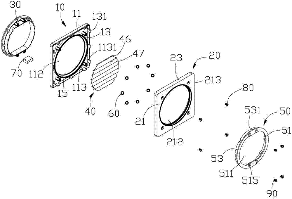
图1是本发明风扇百叶窗一较佳实施例的立体分解图。 Fig. 1 is an exploded perspective view of a preferred embodiment of the fan shutter of the present invention.
图2是图1的另一视角图。 FIG. 2 is another perspective view of FIG. 1 .
图3是图1的一局部放大图。 FIG. 3 is a partially enlarged view of FIG. 1 .
图4是图1的一局部组装图。 FIG. 4 is a partial assembly view of FIG. 1 .
图5是图1的一立体组装图。 FIG. 5 is a perspective assembly view of FIG. 1 .
图6是本发明风扇百叶窗一较佳实施例中与一机壳的面板的一立体组装图。 Fig. 6 is a three-dimensional assembly view of a preferred embodiment of the fan louver of the present invention and a panel of a casing.
图7是图6中所述机壳的面板旋转一角度后与本发明风扇百叶窗的一立体组装图。 FIG. 7 is a three-dimensional assembly view of the fan louver of the present invention after the panel of the casing in FIG. 6 is rotated at an angle.
主要元件符号说明 Description of main component symbols
如下具体实施方式将结合上述附图进一步说明本发明。 The following specific embodiments will further illustrate the present invention in conjunction with the above-mentioned drawings.
具体实施方式 Detailed ways
请参阅图1和图2,在本发明的一较佳实施例中,一风扇百叶窗包括一前板10、一后板20、一固定架30、一定位件50及一叶片组合40。
Please refer to FIG. 1 and FIG. 2 , in a preferred embodiment of the present invention, a fan louver includes a
所述前板10包括一第一板体11及自所述第一板体11的四边缘分别延伸的第一折边13。所述第一板体11大致为方形,且在中央开设一圆形的第一安装口112。一安装环15自所述第一安装口112的边缘延伸。所述第一板体11的四角处分别凸设一安装柱113。每一安装柱113开设一安装孔1131。每一第一折边13设有若干弹性卡钩131。
The
所述后板20包括一第二板体21及自所述第二板体21的边缘分别延伸的第二折边23。所述第二板体21大致为方形,且在中央开设一圆形的第二安装口212。所述第二板体21的四角处分别开设一锁孔213。每一第二折边23开设若干卡槽231,用以卡扣所述卡钩131。
The
请同时参阅图3,所述固定架30包括一固定板31、自所述固定板31延伸的固定环32及固定部35。所述固定板31开设一第一固定口311。所述固定部35沿所述第一固定口311的边缘延伸形成,且包括两相对的第一固定片351及两相对的第二固定片352。在一实施方式中,所述第一固定片351相互平行,所述第二固定片352为弧形片体。所述固定环32围绕所述固定部35,且沿所述固定部35方向设有若干第一收容槽321。在一实施方式中,每两相邻的第一收容槽321之间的距离相等。所述固定板31在每一第一固定片351与所述固定环32之间凸设两固定柱315。每一固定柱315开设一固定孔3151。两所述第二固定片352在对应的位置开设若干对固定槽3521。所述固定槽3521可用以安装所述叶片组合40。
Please also refer to FIG. 3 , the
所述定位件50包括一定位板51及自所述定位板51延伸的定位环53。所述定位板51开设一第二固定口511。所述第二固定口511的形状与所述第一固定口311大致相同。所述定位板51对应所述固定柱315设有若干定位孔515。所述定位环53向内凹设若干第二收容槽531。在一实施方式中,每两相邻的第二收容槽531之间的距离相等。
The
所述叶片组合40包括若干叶片47、及固定在所述叶片47上枢转轴46。每一叶片47分别包括一固定部471和一自由部473,所述固定部471固定在枢转轴46上。每一叶片47可与相应的枢转轴46一起转动。
The
所述风扇百叶窗还包括有若干滚珠60及一重块70。所述滚珠60可用以收容在所述第一收容槽321及所述第二收容槽531之间。所述重块70可用以收容在位于一所述第一固定片351一侧的两固定柱315之间而固定到所述固定板31上。
The fan shutter also includes
请参阅图4及图5,安装时,将所述固定架30靠近所述前板10。移动所述固定架30,使所述固定部35、所述固定柱315及所述固定环32穿过所述前板10的第一安装口112,且位于所述安装环15之间。所述固定板31抵靠在所述第一板体11上。将所述固定架30及所述前板10水平放置在一安装面(图未示)上,且所述固定板31及所述第一板体11大致平行所述安装面。将所述滚珠60放置在所述第一收容槽321中,且位于所述安装环15及所述固定部35之间。将所述叶片47的枢转轴46放置在每对所述固定槽3521中。在上下相邻的两叶片47中,上方叶片47的自由部473的内侧压在下方叶片47的固定部471的外侧上。将所述重块70放置在所述固定架30一端的两固定柱315之间而固定到所述前板固定板31上。所述重块70位于所述第一固定片351及所述固定环32之间。将所述后板20沿靠近所述前板10方向移动。所述后板20驱使所述前板10的卡钩131弹性形变。当所述卡钩131对齐所述后板20的卡槽231,所述卡钩131弹性回复,从而卡扣在所述卡槽231中。此时,所述锁孔213对齐所述安装柱113的安装孔1131。利用若干第一锁固件80,如螺丝等旋入所述安装孔1131及所述固定孔3151,将所述后板20固定在所述前板10上。将所述定位件50沿靠近所述后板20方向移动,所述定位环53对齐所述第二安装口212,所述第二收容槽531对齐所述第一收容槽321,且所述定位孔515对齐所述固定柱315的固定孔3151。移动所述定位件50,直到所述定位板51抵靠在所述第二板体21的外表面上。利用若干第二锁固件90,如螺丝等穿过所述定位孔515及所述固定孔3151,从而将所述定位件50固定在所述固定架30上,则所述固定架30、所述叶片组合40、和所述定位件50固定在一起,并容置于所述前板10的第一安装口112和所述后板20的第二安装口212中,且由于所述滚珠60与所述安装环15的内壁接触,且可沿着所述安装环15的内壁滑动,则所述固定架30、所述叶片组合40、和所述定位件50可在所述第一安装口112和所述第二安装口212中转动。所述定位板51大致平行所述固定板31,且所述固定环32与所述定位环53位于所述定位板51及所述固定板31之间。此时,所述叶片组合40转动固定在所述定位件50与所述固定架30之间,且所述叶片47可绕所述枢转轴46转动,所述重块70位于在所述定位板51及所述第一板体11之间,所述定位环53与所述固定环32相抵靠,且所述滚珠60滑动收容在所述第一收容槽321及所述第二收容槽531之间。所述前板10及所述后板20在所述滚珠60的在作用下相对所述固定架30及所述定位件50绕一转轴(图未示)转动。所述转轴大致垂直所述枢转轴46。
Referring to FIG. 4 and FIG. 5 , during installation, the fixing
请参阅图6和图7,使用时,所述风扇百叶窗的后板20通过一固定架(图未示)固定一机壳的面板100上。当转动所述机壳时,所述面板100沿方向A或方向B转动。所述前板10及所述后板20相应地沿方向A或方向B转动。在所述重块70及所述滚珠60的作用下,所述固定架30及所述定位件50不会随所述前板10及所述后板20转动。从而,所述固定架30及所述定位件50的位置不变。所述叶片组合40的位置也不会改变。这样,就不需要手动来调整所述叶片组合40的位置。
Please refer to FIG. 6 and FIG. 7 , when in use, the
Claims (10)
Priority Applications (3)
| Application Number | Priority Date | Filing Date | Title |
|---|---|---|---|
| CN201210055011.0A CN103298316A (en) | 2012-03-05 | 2012-03-05 | Fan louver |
| TW101107599A TW201337109A (en) | 2012-03-05 | 2012-03-07 | Fan shutter |
| US13/688,435 US20130231041A1 (en) | 2012-03-05 | 2012-11-29 | Air guiding apparatus |
Applications Claiming Priority (1)
| Application Number | Priority Date | Filing Date | Title |
|---|---|---|---|
| CN201210055011.0A CN103298316A (en) | 2012-03-05 | 2012-03-05 | Fan louver |
Publications (1)
| Publication Number | Publication Date |
|---|---|
| CN103298316A true CN103298316A (en) | 2013-09-11 |
Family
ID=49043103
Family Applications (1)
| Application Number | Title | Priority Date | Filing Date |
|---|---|---|---|
| CN201210055011.0A Pending CN103298316A (en) | 2012-03-05 | 2012-03-05 | Fan louver |
Country Status (3)
| Country | Link |
|---|---|
| US (1) | US20130231041A1 (en) |
| CN (1) | CN103298316A (en) |
| TW (1) | TW201337109A (en) |
Families Citing this family (6)
| Publication number | Priority date | Publication date | Assignee | Title |
|---|---|---|---|---|
| WO2015193384A2 (en) | 2014-06-17 | 2015-12-23 | Tyco Electronics Raychem Bvba | Cable distribution system |
| CN104405686B (en) * | 2014-12-06 | 2016-08-24 | 漳州永裕隆精密五金有限公司 | A kind of negative-pressure air fan |
| US10637220B2 (en) | 2016-01-28 | 2020-04-28 | CommScope Connectivity Belgium BVBA | Modular hybrid closure |
| US10383256B2 (en) * | 2016-03-02 | 2019-08-13 | Dell Products L.P. | Systems and methods for preventing airflow recirculation in an information handling system |
| KR102615769B1 (en) * | 2018-05-18 | 2023-12-20 | 삼성전자주식회사 | Memory device |
| USD925029S1 (en) * | 2019-03-28 | 2021-07-13 | Airmaster A/S | Air vents |
Family Cites Families (2)
| Publication number | Priority date | Publication date | Assignee | Title |
|---|---|---|---|---|
| GB2284474A (en) * | 1993-11-02 | 1995-06-07 | Hunter Technical Dev Ltd | Heating ventilating and air conditioning systems |
| TWI349072B (en) * | 2008-07-04 | 2011-09-21 | Inventec Corp | Wind guiding cover |
-
2012
- 2012-03-05 CN CN201210055011.0A patent/CN103298316A/en active Pending
- 2012-03-07 TW TW101107599A patent/TW201337109A/en unknown
- 2012-11-29 US US13/688,435 patent/US20130231041A1/en not_active Abandoned
Also Published As
| Publication number | Publication date |
|---|---|
| TW201337109A (en) | 2013-09-16 |
| US20130231041A1 (en) | 2013-09-05 |
Similar Documents
| Publication | Publication Date | Title |
|---|---|---|
| CN103298316A (en) | Fan louver | |
| US8451605B2 (en) | Enclosure of electronic apparatus | |
| US20130277512A1 (en) | Mounting apparatus for data storage device | |
| CN103105910A (en) | Electronic device shell | |
| CN103079380A (en) | Fan module and cabinet provided with same | |
| CN103369915A (en) | Wind resistance device and electronic product with wind resistance device | |
| CN103458651B (en) | Fan fixer | |
| US8596472B2 (en) | Electronic device enclosure | |
| US20140154067A1 (en) | Electronic device assembly with fan | |
| CN101625583A (en) | Wind scooper | |
| CN106550568A (en) | Case of electronic device | |
| TW201302029A (en) | Stand for electronic device | |
| TW201405956A (en) | Catching device for motherboard | |
| CN103425186A (en) | Fan louver | |
| CN200997303Y (en) | Pivoting positioning structure of magnetic retainer | |
| CN103885553A (en) | Data memory fixing device | |
| CN103186189A (en) | Mainboard fixing device | |
| CN102562624A (en) | Fan combination | |
| TWI543698B (en) | Fixture for electronic device | |
| CN102109890B (en) | Computer case | |
| CN109917878A (en) | Air guide mechanism, case and electronic device using the same | |
| US20120267508A1 (en) | Mounting apparatus for fan | |
| TW201448719A (en) | Air duct module and electronic device with air duct module | |
| CN104582336B (en) | cabinet | |
| CN102346516A (en) | Computer cabinet |
Legal Events
| Date | Code | Title | Description |
|---|---|---|---|
| C06 | Publication | ||
| PB01 | Publication | ||
| C02 | Deemed withdrawal of patent application after publication (patent law 2001) | ||
| WD01 | Invention patent application deemed withdrawn after publication |
Application publication date: 20130911 |