CN103282304A - Apparatuses, systems and methods for efficient solubilization of carbon dioxide in water using high energy impact - Google Patents
Apparatuses, systems and methods for efficient solubilization of carbon dioxide in water using high energy impact Download PDFInfo
- Publication number
- CN103282304A CN103282304A CN201180033123XA CN201180033123A CN103282304A CN 103282304 A CN103282304 A CN 103282304A CN 201180033123X A CN201180033123X A CN 201180033123XA CN 201180033123 A CN201180033123 A CN 201180033123A CN 103282304 A CN103282304 A CN 103282304A
- Authority
- CN
- China
- Prior art keywords
- water
- carbonic acid
- acid gas
- carbon dioxide
- conduit
- Prior art date
- Legal status (The legal status is an assumption and is not a legal conclusion. Google has not performed a legal analysis and makes no representation as to the accuracy of the status listed.)
- Pending
Links
Images


Classifications
-
- B—PERFORMING OPERATIONS; TRANSPORTING
- B01—PHYSICAL OR CHEMICAL PROCESSES OR APPARATUS IN GENERAL
- B01F—MIXING, e.g. DISSOLVING, EMULSIFYING OR DISPERSING
- B01F23/00—Mixing according to the phases to be mixed, e.g. dispersing or emulsifying
- B01F23/20—Mixing gases with liquids
- B01F23/23—Mixing gases with liquids by introducing gases into liquid media, e.g. for producing aerated liquids
- B01F23/236—Mixing gases with liquids by introducing gases into liquid media, e.g. for producing aerated liquids specially adapted for aerating or carbonating beverages
- B01F23/2362—Mixing gases with liquids by introducing gases into liquid media, e.g. for producing aerated liquids specially adapted for aerating or carbonating beverages for aerating or carbonating within receptacles or tanks, e.g. distribution machines
-
- A—HUMAN NECESSITIES
- A23—FOODS OR FOODSTUFFS; TREATMENT THEREOF, NOT COVERED BY OTHER CLASSES
- A23L—FOODS, FOODSTUFFS OR NON-ALCOHOLIC BEVERAGES, NOT OTHERWISE PROVIDED FOR; PREPARATION OR TREATMENT THEREOF
- A23L2/00—Non-alcoholic beverages; Dry compositions or concentrates therefor; Preparation or treatment thereof
- A23L2/52—Adding ingredients
- A23L2/54—Mixing with gases
-
- B—PERFORMING OPERATIONS; TRANSPORTING
- B01—PHYSICAL OR CHEMICAL PROCESSES OR APPARATUS IN GENERAL
- B01F—MIXING, e.g. DISSOLVING, EMULSIFYING OR DISPERSING
- B01F21/00—Dissolving
-
- A—HUMAN NECESSITIES
- A47—FURNITURE; DOMESTIC ARTICLES OR APPLIANCES; COFFEE MILLS; SPICE MILLS; SUCTION CLEANERS IN GENERAL
- A47J—KITCHEN EQUIPMENT; COFFEE MILLS; SPICE MILLS; APPARATUS FOR MAKING BEVERAGES
- A47J31/00—Apparatus for making beverages
-
- B—PERFORMING OPERATIONS; TRANSPORTING
- B01—PHYSICAL OR CHEMICAL PROCESSES OR APPARATUS IN GENERAL
- B01F—MIXING, e.g. DISSOLVING, EMULSIFYING OR DISPERSING
- B01F23/00—Mixing according to the phases to be mixed, e.g. dispersing or emulsifying
- B01F23/20—Mixing gases with liquids
-
- B—PERFORMING OPERATIONS; TRANSPORTING
- B01—PHYSICAL OR CHEMICAL PROCESSES OR APPARATUS IN GENERAL
- B01F—MIXING, e.g. DISSOLVING, EMULSIFYING OR DISPERSING
- B01F23/00—Mixing according to the phases to be mixed, e.g. dispersing or emulsifying
- B01F23/20—Mixing gases with liquids
- B01F23/23—Mixing gases with liquids by introducing gases into liquid media, e.g. for producing aerated liquids
- B01F23/232—Mixing gases with liquids by introducing gases into liquid media, e.g. for producing aerated liquids using flow-mixing means for introducing the gases, e.g. baffles
- B01F23/2323—Mixing gases with liquids by introducing gases into liquid media, e.g. for producing aerated liquids using flow-mixing means for introducing the gases, e.g. baffles by circulating the flow in guiding constructions or conduits
-
- B—PERFORMING OPERATIONS; TRANSPORTING
- B01—PHYSICAL OR CHEMICAL PROCESSES OR APPARATUS IN GENERAL
- B01F—MIXING, e.g. DISSOLVING, EMULSIFYING OR DISPERSING
- B01F23/00—Mixing according to the phases to be mixed, e.g. dispersing or emulsifying
- B01F23/20—Mixing gases with liquids
- B01F23/23—Mixing gases with liquids by introducing gases into liquid media, e.g. for producing aerated liquids
- B01F23/236—Mixing gases with liquids by introducing gases into liquid media, e.g. for producing aerated liquids specially adapted for aerating or carbonating beverages
-
- B—PERFORMING OPERATIONS; TRANSPORTING
- B01—PHYSICAL OR CHEMICAL PROCESSES OR APPARATUS IN GENERAL
- B01F—MIXING, e.g. DISSOLVING, EMULSIFYING OR DISPERSING
- B01F23/00—Mixing according to the phases to be mixed, e.g. dispersing or emulsifying
- B01F23/20—Mixing gases with liquids
- B01F23/29—Mixing systems, i.e. flow charts or diagrams
-
- B—PERFORMING OPERATIONS; TRANSPORTING
- B01—PHYSICAL OR CHEMICAL PROCESSES OR APPARATUS IN GENERAL
- B01F—MIXING, e.g. DISSOLVING, EMULSIFYING OR DISPERSING
- B01F25/00—Flow mixers; Mixers for falling materials, e.g. solid particles
- B01F25/20—Jet mixers, i.e. mixers using high-speed fluid streams
-
- B—PERFORMING OPERATIONS; TRANSPORTING
- B01—PHYSICAL OR CHEMICAL PROCESSES OR APPARATUS IN GENERAL
- B01F—MIXING, e.g. DISSOLVING, EMULSIFYING OR DISPERSING
- B01F25/00—Flow mixers; Mixers for falling materials, e.g. solid particles
- B01F25/30—Injector mixers
-
- B—PERFORMING OPERATIONS; TRANSPORTING
- B01—PHYSICAL OR CHEMICAL PROCESSES OR APPARATUS IN GENERAL
- B01F—MIXING, e.g. DISSOLVING, EMULSIFYING OR DISPERSING
- B01F25/00—Flow mixers; Mixers for falling materials, e.g. solid particles
- B01F25/40—Static mixers
-
- B—PERFORMING OPERATIONS; TRANSPORTING
- B01—PHYSICAL OR CHEMICAL PROCESSES OR APPARATUS IN GENERAL
- B01F—MIXING, e.g. DISSOLVING, EMULSIFYING OR DISPERSING
- B01F25/00—Flow mixers; Mixers for falling materials, e.g. solid particles
- B01F25/40—Static mixers
- B01F25/42—Static mixers in which the mixing is affected by moving the components jointly in changing directions, e.g. in tubes provided with baffles or obstructions
- B01F25/43—Mixing tubes, e.g. wherein the material is moved in a radial or partly reversed direction
- B01F25/431—Straight mixing tubes with baffles or obstructions that do not cause substantial pressure drop; Baffles therefor
- B01F25/4314—Straight mixing tubes with baffles or obstructions that do not cause substantial pressure drop; Baffles therefor with helical baffles
- B01F25/43141—Straight mixing tubes with baffles or obstructions that do not cause substantial pressure drop; Baffles therefor with helical baffles composed of consecutive sections of helical formed elements
-
- B—PERFORMING OPERATIONS; TRANSPORTING
- B01—PHYSICAL OR CHEMICAL PROCESSES OR APPARATUS IN GENERAL
- B01F—MIXING, e.g. DISSOLVING, EMULSIFYING OR DISPERSING
- B01F25/00—Flow mixers; Mixers for falling materials, e.g. solid particles
- B01F25/40—Static mixers
- B01F25/42—Static mixers in which the mixing is affected by moving the components jointly in changing directions, e.g. in tubes provided with baffles or obstructions
- B01F25/43—Mixing tubes, e.g. wherein the material is moved in a radial or partly reversed direction
- B01F25/432—Mixing tubes, e.g. wherein the material is moved in a radial or partly reversed direction with means for dividing the material flow into separate sub-flows and for repositioning and recombining these sub-flows; Cross-mixing, e.g. conducting the outer layer of the material nearer to the axis of the tube or vice-versa
- B01F25/4321—Mixing tubes, e.g. wherein the material is moved in a radial or partly reversed direction with means for dividing the material flow into separate sub-flows and for repositioning and recombining these sub-flows; Cross-mixing, e.g. conducting the outer layer of the material nearer to the axis of the tube or vice-versa the subflows consisting of at least two flat layers which are recombined, e.g. using means having restriction or expansion zones
-
- B—PERFORMING OPERATIONS; TRANSPORTING
- B01—PHYSICAL OR CHEMICAL PROCESSES OR APPARATUS IN GENERAL
- B01F—MIXING, e.g. DISSOLVING, EMULSIFYING OR DISPERSING
- B01F25/00—Flow mixers; Mixers for falling materials, e.g. solid particles
- B01F25/40—Static mixers
- B01F25/45—Mixers in which the materials to be mixed are pressed together through orifices or interstitial spaces, e.g. between beads
- B01F25/452—Mixers in which the materials to be mixed are pressed together through orifices or interstitial spaces, e.g. between beads characterised by elements provided with orifices or interstitial spaces
- B01F25/4521—Mixers in which the materials to be mixed are pressed together through orifices or interstitial spaces, e.g. between beads characterised by elements provided with orifices or interstitial spaces the components being pressed through orifices in elements, e.g. flat plates or cylinders, which obstruct the whole diameter of the tube
-
- B—PERFORMING OPERATIONS; TRANSPORTING
- B01—PHYSICAL OR CHEMICAL PROCESSES OR APPARATUS IN GENERAL
- B01F—MIXING, e.g. DISSOLVING, EMULSIFYING OR DISPERSING
- B01F31/00—Mixers with shaking, oscillating, or vibrating mechanisms
- B01F31/80—Mixing by means of high-frequency vibrations above one kHz, e.g. ultrasonic vibrations
- B01F31/81—Mixing by means of high-frequency vibrations above one kHz, e.g. ultrasonic vibrations by vibrations generated inside a mixing device not coming from an external drive, e.g. by the flow of material causing a knife to vibrate or by vibrating nozzles
-
- A—HUMAN NECESSITIES
- A23—FOODS OR FOODSTUFFS; TREATMENT THEREOF, NOT COVERED BY OTHER CLASSES
- A23V—INDEXING SCHEME RELATING TO FOODS, FOODSTUFFS OR NON-ALCOHOLIC BEVERAGES AND LACTIC OR PROPIONIC ACID BACTERIA USED IN FOODSTUFFS OR FOOD PREPARATION
- A23V2002/00—Food compositions, function of food ingredients or processes for food or foodstuffs
-
- B—PERFORMING OPERATIONS; TRANSPORTING
- B01—PHYSICAL OR CHEMICAL PROCESSES OR APPARATUS IN GENERAL
- B01F—MIXING, e.g. DISSOLVING, EMULSIFYING OR DISPERSING
- B01F2101/00—Mixing characterised by the nature of the mixed materials or by the application field
- B01F2101/06—Mixing of food ingredients
- B01F2101/14—Mixing of ingredients for non-alcoholic beverages; Dissolving sugar in water
-
- B—PERFORMING OPERATIONS; TRANSPORTING
- B01—PHYSICAL OR CHEMICAL PROCESSES OR APPARATUS IN GENERAL
- B01F—MIXING, e.g. DISSOLVING, EMULSIFYING OR DISPERSING
- B01F2215/00—Auxiliary or complementary information in relation with mixing
- B01F2215/04—Technical information in relation with mixing
- B01F2215/0413—Numerical information
- B01F2215/0436—Operational information
- B01F2215/045—Numerical flow-rate values
-
- B—PERFORMING OPERATIONS; TRANSPORTING
- B01—PHYSICAL OR CHEMICAL PROCESSES OR APPARATUS IN GENERAL
- B01F—MIXING, e.g. DISSOLVING, EMULSIFYING OR DISPERSING
- B01F2215/00—Auxiliary or complementary information in relation with mixing
- B01F2215/04—Technical information in relation with mixing
- B01F2215/0413—Numerical information
- B01F2215/0436—Operational information
- B01F2215/0468—Numerical pressure values
-
- Y—GENERAL TAGGING OF NEW TECHNOLOGICAL DEVELOPMENTS; GENERAL TAGGING OF CROSS-SECTIONAL TECHNOLOGIES SPANNING OVER SEVERAL SECTIONS OF THE IPC; TECHNICAL SUBJECTS COVERED BY FORMER USPC CROSS-REFERENCE ART COLLECTIONS [XRACs] AND DIGESTS
- Y02—TECHNOLOGIES OR APPLICATIONS FOR MITIGATION OR ADAPTATION AGAINST CLIMATE CHANGE
- Y02C—CAPTURE, STORAGE, SEQUESTRATION OR DISPOSAL OF GREENHOUSE GASES [GHG]
- Y02C20/00—Capture or disposal of greenhouse gases
- Y02C20/40—Capture or disposal of greenhouse gases of CO2
Landscapes
- Chemical & Material Sciences (AREA)
- Chemical Kinetics & Catalysis (AREA)
- Dispersion Chemistry (AREA)
- Engineering & Computer Science (AREA)
- Food Science & Technology (AREA)
- Health & Medical Sciences (AREA)
- Nutrition Science (AREA)
- Life Sciences & Earth Sciences (AREA)
- Polymers & Plastics (AREA)
- Accessories For Mixers (AREA)
- Non-Alcoholic Beverages (AREA)
Abstract
Description
技术领域technical field
本发明涉及用以将气体溶解在液体中的装置、系统和方法,尤其是用于生产供人消费的碳酸饮料。The present invention relates to apparatus, systems and methods for dissolving gases in liquids, especially for producing carbonated beverages for human consumption.
背景技术Background technique
在通常的环境条件,即,室温和大气压力下,水和二氧化碳一般不相溶。通过创造使得二氧化碳可溶于水的条件来制备碳酸水的装置和方法是公知的。一般而言,当压力增大且温度降低时,二氧化碳在水中溶解度增大。Water and carbon dioxide are generally immiscible under normal ambient conditions, ie, room temperature and atmospheric pressure. Apparatus and methods for producing carbonated water by creating conditions such that carbon dioxide is soluble in water are known. In general, the solubility of carbon dioxide in water increases as the pressure increases and the temperature decreases.
大部分用于碳酸化水的商业化装置使用喷射到水容器中的二氧化碳:这种方法得到的结果非常不好,并且水的碳酸化微弱,且不能维持很长时间。而另外,用于在水分配单元制备和分配碳酸饮料的装置,一般使用被称作饱和器的碳酸储槽、以及高压水泵。通过用二氧化碳对饱和器储槽加压并用冷冻水充满储槽来制备碳酸水。由于饱和器储槽中的高压(一般在大约70psi),需要相对昂贵的高压水泵将水注射到储槽中。此外,在饱和器储槽中的条件下,需要花费时间来使得二氧化碳溶解在水中并实现可口的碳酸化水平。因此,饱和器一般足够大以保持碳酸水的预备供应以供分配,并且不能根据需要即时地制造新的碳酸水。为了维持供应,使用两个或更多个传感器以及相关的电子控制器,以在饱和器中的碳酸水的水位下降到设定的临界值时,启动高压泵并将水注射到饱和器中,并当储槽被充满到适当水位时,停止水的注射。Most commercial units for carbonating water use carbon dioxide sprayed into the water container: this method gives very poor results, and the water is weakly carbonated and does not last very long. Yet further, devices for preparing and dispensing carbonated beverages in water dispensing units generally use a carbonation storage tank called a saturator, and a high pressure water pump. Carbonated water is produced by pressurizing the saturator reservoir with carbon dioxide and filling the reservoir with chilled water. Due to the high pressure in the saturator sump (typically around 70 psi), relatively expensive high pressure water pumps are required to inject water into the sump. Furthermore, under the conditions in the saturator tank, it takes time for the carbon dioxide to dissolve in the water and achieve a palatable level of carbonation. Thus, saturators are generally large enough to maintain a ready supply of carbonated water for dispensing, and cannot make new carbonated water on-the-fly as needed. To maintain the supply, two or more sensors and associated electronic controllers are used to activate the high-pressure pump and inject water into the saturator when the level of carbonated water in the saturator drops below a set threshold, And when the storage tank is filled to the proper water level, the injection of water is stopped.
这些典型的碳化装置相对而言占据很大的空间,且需要昂贵复杂的电子和液力控制系统。由于这种复杂结构,这些装置噪音很大,耗能非常高,并且需要频繁的维护。These typical carbonization units take up a relatively large amount of space and require expensive and complex electronic and hydraulic control systems. Due to this complex structure, these devices are noisy, consume a lot of energy and require frequent maintenance.
发明内容Contents of the invention
本发明公开的实施例教导了二氧化碳在水中溶解的高效且价廉的方法、装置和系统。The disclosed embodiments of the present invention teach efficient and inexpensive methods, devices and systems for the dissolution of carbon dioxide in water.
根据本发明的一个例示性实施例,公开了一种使二氧化碳溶解在水中的方法。在该方法中,首先将水和二氧化碳注射到腔室中。使二氧化碳和水混合以在腔室中形成环形分散流。然后这种分散流被加速并被引导以碰撞坚硬表面,从而产生足以使二氧化碳溶解在水中的压力。然后对所得到的碳酸水加以收集以便分配。According to an exemplary embodiment of the present invention, a method of dissolving carbon dioxide in water is disclosed. In this method, water and carbon dioxide are first injected into the chamber. Carbon dioxide and water are mixed to form an annular dispersed flow in the chamber. This dispersed flow is then accelerated and directed to hit a hard surface, creating pressure sufficient to dissolve the carbon dioxide in the water. The resulting carbonated water is then collected for distribution.
根据本发明的另一个例示性实施例,公开了一种可被放置在水管线路径上以制造供分配的碳酸水的装置。有利地,该装置通过进口路径接纳二氧化碳和水。由此,二氧化碳和水的流通过布置在导管中的一个或更多个分散元件,以形成分散流。然后分散流通过导管中的被动加速器,从而极大地增大系统的动能。加速流被导向以撞击在被动加速器紧下游的坚硬表面。这种撞击产生足以使二氧化碳溶解在水中的压力。在装置的出口处设有滞留机构,用以收集并调节碳酸水流。According to another exemplary embodiment of the present invention, an apparatus that may be placed on a water line path to produce carbonated water for dispensing is disclosed. Advantageously, the device receives carbon dioxide and water through an inlet path. Thereby, the flow of carbon dioxide and water passes through one or more dispersing elements arranged in the conduit to form a dispersing flow. The dispersed flow is then passed through a passive accelerator in the conduit, greatly increasing the kinetic energy of the system. The accelerated flow is directed to impinge on a hard surface immediately downstream of the passive accelerator. This impact creates enough pressure to dissolve the carbon dioxide in the water. A stagnation mechanism is provided at the outlet of the device to collect and regulate the flow of carbonated water.
在详细公开中描述包括所公开方法、装置和系统的有利方面的更多实施例。在这里所有的公开都仅仅是例示性的,并且本领域技术人员可以在不脱离所公开和所主张的本发明的精神和范围的情况下,容易地做出适当调整。Further embodiments including advantageous aspects of the disclosed methods, apparatuses and systems are described in the detailed disclosure. All disclosures herein are exemplary only, and appropriate modifications can be readily made by those skilled in the art without departing from the spirit and scope of the invention disclosed and claimed.
附图说明Description of drawings
附图阐明了根据本发明的各种非限制性的、有代表性的、有创造性的方面:The accompanying drawings illustrate various non-limiting, representative, inventive aspects according to the invention:
图1A示出了所公开的方法、系统和装置的一个方面的概念图。Figure 1A shows a conceptual diagram of one aspect of the disclosed methods, systems and apparatus.
图1B示出了所公开的方法、系统和装置的一个方面。Figure IB illustrates one aspect of the disclosed methods, systems and apparatus.
图2A和2B示出了所公开的方法、系统和装置的一个方面的概念图。2A and 2B illustrate conceptual diagrams of one aspect of the disclosed methods, systems and apparatus.
图3示出了根据公开的方法和装置所使用的系统的一个实施例。Figure 3 illustrates one embodiment of a system used in accordance with the disclosed methods and apparatus.
图4是根据公开的系统和方法所使用的装置的一个实施例。Figure 4 is one embodiment of a device used in accordance with the disclosed systems and methods.
图5A和5B示出了所公开的方法、系统和装置的一个方面的概念图。5A and 5B illustrate conceptual diagrams of one aspect of the disclosed methods, systems and apparatus.
图6是所公开的系统和方法所使用的装置的一个实施例。Figure 6 is one embodiment of an apparatus used by the disclosed systems and methods.
图7是所公开的系统和方法所使用的装置的一个实施例。Figure 7 is one embodiment of an apparatus used by the disclosed systems and methods.
图8是所公开的系统和方法所使用的装置的一个实施例。Figure 8 is one embodiment of an apparatus used by the disclosed systems and methods.
图9是所公开的系统和方法所使用的装置的一个实施例。Figure 9 is one embodiment of an apparatus used by the disclosed systems and methods.
具体实施方式Detailed ways
在这里公开了使二氧化碳在水中快速并高效溶解的装置、系统和方法。具体地说,通过将动能瞬时地转化为局部压力波,以产生带有足以使二氧化碳溶解在水中的能量密度的区域,来制备碳酸水。这可以通过使用与水供应器成一直线以制造一个连续的碳酸水流的装置而实现。Disclosed herein are devices, systems and methods for the rapid and efficient dissolution of carbon dioxide in water. Specifically, carbonated water is produced by instantaneously converting kinetic energy into localized pressure waves to create a region with an energy density sufficient to dissolve carbon dioxide in water. This can be accomplished by using a device in line with the water supply to create a continuous stream of carbonated water.
所公开的方法的一个特别有利的方面是通过二氧化碳/水的流束与坚硬表面的碰撞而使二氧化碳溶解在水中。图1A示出了根据本发明的一个示范性碰撞中所发生的相互作用的概念图。A particularly advantageous aspect of the disclosed method is the dissolution of carbon dioxide in water by the impingement of a stream of carbon dioxide/water against a hard surface. FIG. 1A shows a conceptual diagram of the interactions that occur in an exemplary collision according to the present invention.
如图1A中所示,将二氧化碳/水的流束2引导至一个坚硬表面,例如壁1。在与壁碰撞下流束2的动量突然变为零,从而产生能量密度高并且局部压力非常大的区域3。由碰撞结果形成的巨大压力使二氧化碳溶解在水中。As shown in FIG. 1A , a stream 2 of carbon dioxide/water is directed to a hard surface, such as a
在压力区域3,在以下各者之间制造发生溶解的大量的瞬间碰撞:二氧化碳/水的混合物和坚硬表面;流入的流束和由坚硬表面反弹的二氧化碳和水滴(即,散射混合物);以及散射混合物和运送流束的导管侧壁。In pressure zone 3, a large number of momentary collisions where dissolution occurs is created between: the carbon dioxide/water mixture and the hard surface; the incoming stream and the carbon dioxide and water droplets bouncing off the hard surface (i.e., the scattering mixture); and Scatter the mixture and the sidewall of the conduit that carries the stream.
当二氧化碳/水的流束与坚硬表面碰撞时发生的动量改变导致了施加在流束上的作用力。像所有动量改变一样,用于产生改变的力是改变发生的时间的函数。因为当二氧化碳/水流与坚硬壁碰撞时动量的改变近乎是瞬时性的,所以力是在非常短的时间内施加的,因而相当大。The change in momentum that occurs when the CO2/water stream collides with a hard surface results in the force exerted on the stream. Like all momentum changes, the force used to produce the change is a function of the time at which the change occurs. Because the change in momentum is near-instantaneous when the CO2/water stream collides with a hard wall, the force is applied in a very short time and is therefore quite large.
必须在高效地溶解的区域内获得的、在压力区域产生的最优的力或者压力能量密度必须在-40至5英尺-磅/cm3范围内。图1B是示出了压力能量密度随着二氧化碳/水流束速率变化的图。当二氧化碳/水流束速率增大时,压力能量密度减小以补偿动能密度的增大。然后这种压力能量密度的下降被倒转,以增大坚硬壁1和压力区域3中气体/液体界面的碰撞力。The optimum force or pressure energy density generated in the pressure region must be in the range of -40 to 5 foot-pounds/cm 3 , which must be achieved in the region of efficient dissolution. Figure IB is a graph showing pressure energy density as a function of carbon dioxide/water stream rate. When the CO2/water flow rate increases, the pressure energy density decreases to compensate for the increase in kinetic energy density. This drop in pressure energy density is then reversed to increase the collision force of the
当二氧化碳/水的混合流束与坚硬壁碰撞时,产生的撞击力是瞬时的(时间=0)。当时间连续地推进(时间=t1......tn)时,在进入的二氧化碳和水分子与已溶解的具有不同的方向速度的二氧化碳和水分子之间产生进一步的碰撞力。积累的链反应是在一个给定的时间段里施加在流体的每一段上的力作为持续以及瞬间的动量转化而将两个阶段彼此进一步合并,由此,制造出二氧化碳已彻底地完全地溶解的碳酸水。When the mixed stream of carbon dioxide/water collides with a hard wall, the resulting impact force is instantaneous (time = 0). As time progresses continuously (time = t 1 . . . t n ), further collision forces are generated between incoming carbon dioxide and water molecules and dissolved carbon dioxide and water molecules having different directional velocities. The cumulative chain reaction is the force exerted on each segment of the fluid for a given period of time as a continuous as well as a momentary conversion of momentum to further merge the two phases into each other, thereby producing carbon dioxide that has been thoroughly and completely dissolved carbonated water.
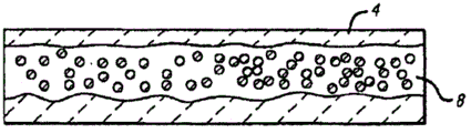
构造水/二氧化碳流束可以进一步增强二氧化碳在碰撞点的溶解。不构造水/二氧化碳流束将会趋向形成分层配置,其中二氧化碳和水在实质上离散的水层4和二氧化碳层7层中流动,如图2A所示。这些层抑制最佳的溶解,因为它们在二氧化碳和水之间提供有限量的表面区域。这种有限的表面接触区域,降低了二氧化碳溶解在水中的机会。构造水/二氧化碳流束以阻止大致层状流,修正了这种问题。Constructing the water/CO2 stream can further enhance CO2 dissolution at the collision point. Not configuring the water/carbon dioxide stream will tend to form a stratified configuration in which the carbon dioxide and water flow in substantially discrete layers of water 4 and carbon dioxide 7, as shown in Figure 2A. These layers inhibit optimal dissolution because they provide a limited amount of surface area between carbon dioxide and water. This limited surface contact area reduces the chance of carbon dioxide dissolving in the water. Constructing the water/CO2 stream to stop the roughly laminar flow corrects this problem.
构造的一般目的是,制造与二氧化碳流束均匀混合的水滴分散流,以增大两种物质之间的总接触表面积。实际上,流动形式从未变得完全分散,并且产生了一个水4以及分散的水和二氧化碳8的环形分散形式,如图2B中概念性地所示。如图所示,得到的流型(flow)一般具有包含分散的水滴的二氧化碳核心,该核心被沿着管道壁的相当薄的水层包围。The general purpose of the configuration is to create a dispersed stream of water droplets that is uniformly mixed with the carbon dioxide stream to increase the total contact surface area between the two species. In fact, the flow pattern never becomes fully dispersed, and a ring-shaped dispersed pattern of water 4 and dispersed water and carbon dioxide 8 is produced, as conceptually shown in Figure 2B. As shown, the resulting flow generally has a carbon dioxide core containing dispersed water droplets surrounded by a relatively thin layer of water along the pipe wall.
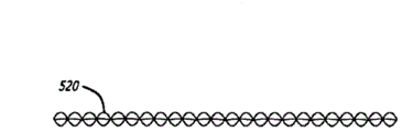
任何本技术领域中已知的制备环形分散流的机制,都可适用于所公开的方法。例如,这种类型的流型可通过在流动路径上的静止混合元件来产生,例如从管道壁伸出的翅片或在流动路径中沿轴向排列的螺旋结构。Any mechanism known in the art for producing annular dispersed flow can be adapted for use in the disclosed method. For example, this type of flow pattern can be created by static mixing elements in the flow path, such as fins protruding from the pipe walls or helical structures arranged axially in the flow path.
二氧化碳在水中的溶解可通过在其与坚硬壁碰撞之前加速二氧化碳/水流束而被进一步增强。优选地,加速通过使流体流经加速器而实现。如本技术领域中已知的那样,由于质量守恒定理,使一个液体流通过限流部件,将导致得到的加速流。这可通过一个简单的孔得到,或通过更复杂的机械结构得到,例如文丘里管。The dissolution of carbon dioxide in water can be further enhanced by accelerating the carbon dioxide/water jet before it collides with a hard wall. Preferably, acceleration is achieved by passing fluid through an accelerator. As is known in the art, passing a flow of liquid through a flow restriction will result in a resulting accelerated flow due to the principle of conservation of mass. This can be achieved with a simple hole, or with a more complex mechanical structure such as a venturi.
加速器用于在碰撞前容易地提高二氧化碳/水流束的动能。因此,对于给定的进口速度和压力,二氧化碳/水流的能量将被提高,且并不需要昂贵的抽吸装置。提高的动能增大了在压力区域实现的压力,由于消耗更多的动能,此情形导致在碰撞点处的溶解得到改善。Accelerators are used to easily increase the kinetic energy of the CO2/water stream prior to collision. Thus, for a given inlet velocity and pressure, the energy of the CO2/water flow will be increased without the need for expensive pumping equipment. The increased kinetic energy increases the pressure achieved in the pressure region, which leads to improved dissolution at the point of collision due to the greater kinetic energy expended.
当分散流被加速时,用限流器加速是特别有利的。分散流通过限流部件有助于保证二氧化碳和水被均一地加速,由此增强了与坚硬表面碰撞时发生的溶解。Acceleration with flow restrictors is particularly advantageous when the dispersed flow is accelerated. Dispersive flow through the restrictor helps to ensure that the carbon dioxide and water are accelerated uniformly, thereby enhancing dissolution upon impact with hard surfaces.
当与坚硬表面碰撞后,可通过在坚硬壁和分配器出口之间使用一个滞留机构(retention network)以在分配之前对流加以调节,而进一步提升二氧化碳的溶解水平。滞留机构允许碳酸水被设定在用以分配的可接受压力下,例如10psi至40psi。滞留机构使通过坚硬表面的高压混乱流体被收集为用于分配的常规连续流体。After impact with a hard surface, CO2 dissolution levels can be further enhanced by using a retention network between the hard wall and the dispenser outlet to convect the flow prior to dispensing. The retention mechanism allows the carbonated water to be set at an acceptable pressure for dispensing, eg, 10 psi to 40 psi. The retention mechanism allows high pressure chaotic fluid passing over hard surfaces to be collected as a regular continuous fluid for dispensing.
除了形成用以供分配的适当流束之外,滞留机构还改善了碳化过程。将滞留机构充满流体有助于保持碰撞区域出口的压力。此情形又导致在压力区域内部更高的压力。相反,在碰撞区域出口相对低的压力(例如大气压力),将允许累积于压力区域中的压力通过碰撞区域的出口迅速释放。In addition to creating a proper stream for distribution, the retention mechanism improves the carbonization process. Filling the retention mechanism with fluid helps maintain pressure at the exit of the impact zone. This situation in turn leads to a higher pressure inside the pressure zone. Conversely, a relatively low pressure (eg, atmospheric pressure) at the outlet of the impingement region will allow pressure built up in the pressure region to be released rapidly through the outlet of the impingement region.
滞留机构允许在碰撞区域出口保持相对高的压力,其可以被逐渐降低至用于分配饮料的合适压力,例如,10psi。The retention mechanism allows a relatively high pressure to be maintained at the impingement zone outlet, which can be gradually reduced to a suitable pressure for dispensing the beverage, eg, 10 psi.
通过滞留机构的压降,依赖于系统的长度、宽度和结构。例如,假定直径恒定,滞留机构长度的增大将会增大通过滞留机构的压降。保持滞留机构的直径恒定在3/16英寸(0.1875英寸),约10英寸长的滞留机构将会造成大约120psi的压降,假定启动压力为大约160psi。The pressure drop across the retention mechanism depends on the length, width and configuration of the system. For example, assuming a constant diameter, increasing the length of the retention mechanism will increase the pressure drop across the retention mechanism. Keeping the diameter of the retention mechanism constant at 3/16 inch (0.1875 inches), a retention mechanism approximately 10 inches long would cause a pressure drop of approximately 120 psi, assuming an activation pressure of approximately 160 psi.
虽然上文所述的高能壁冲击所描述的方法单独地足以制造碳酸饮料,但在碰撞之后,对于(i)流分散、(ii)加速器以及(iii)滞留机构的结合使用,在串联地安装在一起时会产生协同作用。换句话说,增加每一步骤都会进一步改善方法以及输出产品的效果。使用这些附加步骤中的一种或更多种,优选使用全部,能够获得二氧化碳在水混合物中的良好溶解。While the method described above for high-energy wall impact alone is sufficient to produce carbonated beverages, after impact, for the combined use of (i) flow dispersion, (ii) accelerators, and (iii) retention mechanisms, installations in series When together there is synergy. In other words, adding each step further improves the method and the output product. Using one or more, preferably all, of these additional steps, a good dissolution of carbon dioxide in the water mixture can be obtained.
可以通过引入冷却器,例如,冰箱或类似物以降低水的温度,而进一步优化所公开的生产碳酸水的方法。优选在水进入流动促进器、碰撞壁和滞留机构的系统前,冷却器工作以将水冷却,但其可在任一或所有这些位置实施冷却。The disclosed method of producing carbonated water can be further optimized by introducing a cooler, such as a refrigerator or the like, to reduce the temperature of the water. The cooler preferably operates to cool the water before it enters the system of flow promoters, impingement walls and retention mechanisms, but it may effect cooling at any or all of these locations.
也可通过增大系统中水的流动压力,而进一步优化所公开的方法,例如通过使用在流动路径中的泵或来自升高的水供应器的重力自流进料。泵或其它压力增强装置优选在水通过流动促进器与二氧化碳混合之前被设置。泵在意欲安装于任何位置的商用实施例中特别有用,这是因为水压,特别是来自市政水管线的水压可能在各个地点都不相同。为了修正这一点,泵可以在系统中提供恒定的压力。虽然可选地可以使用泵,这里公开的方法可以不需要泵而完成。The disclosed method can also be further optimized by increasing the flow pressure of the water in the system, for example by using a pump in the flow path or gravity feed from an elevated water supply. A pump or other pressure enhancing device is preferably provided before the water is mixed with the carbon dioxide through the flow promoter. Pumps are particularly useful in commercial embodiments intended to be installed in any location because water pressure, especially from municipal water lines, may vary from location to location. To correct for this, a pump can provide a constant pressure in the system. The methods disclosed herein can be performed without pumps, although pumps may optionally be used.
用于实施所公开的方法的一种例示性系统在图3中概念性地示出。二氧化碳供应器10和水供应器20同时供给到直列式溶解器50。直列式溶解器50通向滞留机构60,而滞留机构60又通向分配器70。One exemplary system for implementing the disclosed method is shown conceptually in FIG. 3 . The
二氧化碳供应器10可通过任何已知的供气方式体现。优选使用商业上可得到的CO2罐。二氧化碳供应器一般可通过调节器15连接,该调节器可以向直列式溶解器50提供可控制的供应压力。The
通过水供应器20进一步向系统供给。这种供应器可由简单的市政或井水进料器组成。优选地,水供应器20包括冷却器以便冷却水,因为二氧化碳在较冷的水中更容易溶解。The system is further supplied by a
水供应系统20也可选地包括泵以提供恒定的水压。如上所述,普通家庭或商业水龙头的压力,在各个地点或各个时间都不相同。泵可以保证装置接收恒定的压力,而无论当地供应压力是多少。这种提供恒定供应压力的目的,可在不脱离本发明范围的情况下通过其他已知技术被实现。例如,升高的蓄水池可用重力和适当尺寸的水管提供恒定的水供应压力。The
碰撞腔室的一个例示性实施例如图4所示。借助于具有两个进口(一个进口供应二氧化碳,另一个进口供应水)的Y形进口歧管400,使二氧化碳和水相接触。在这个实施例中,两个进口是同样的且是可互换的。用于将二氧化碳和水引入到碰撞腔室中的歧管可以具有任何其他适当配置形式,例如,T形或F形。在另一个实例中,可以通过在管结构中的同心管而提供这些供应器。Y形或者其它形状的歧管,根据其需要的不同,也可以包括初始分配器,以阻止一种流体流入另外一种供料的进口。此外,也可以在各进口内或各进口的上游使用标准的回流禁止装置。此外,也可以通过在歧管进口处的阀或调节器来控制水流和二氧化碳流。An exemplary embodiment of a collision chamber is shown in FIG. 4 . The carbon dioxide and water phases are brought into contact by means of a Y-shaped
进入的水压力影响通过系统其余部分的流体和压力。最小的压力10psi足以获得满意的流量和碳化。业已发现,在0.1gpm至1.5gpm范围内的流量是特别有利的,但更高的流量也是可接受的。The incoming water pressure affects the fluid and pressure through the rest of the system. A minimum pressure of 10 psi is sufficient for satisfactory flow and carbonation. Flow rates in the range of 0.1 gpm to 1.5 gpm have been found to be particularly advantageous, although higher flows are also acceptable.
二氧化碳在45psi至125psi压力下被提供,优选地,在Y形进口歧管中提供的二氧化碳压力被保持为,与在Y形进口歧管中提供的水压力接近。Carbon dioxide is provided at a pressure of 45psi to 125psi, preferably the carbon dioxide provided in the Y-shaped inlet manifold is maintained at a pressure close to the water pressure provided in the Y-shaped inlet manifold.
在图4的实施例中,流动促进器420设置在流动路径内,在歧管进口后方。流动促进器用于阻止分层的或者层状的二氧化碳/水流。可替代地,流动促进器形成充分分散的流,一般是环形分散流(annular-dispersedflow)。图4的实施例使用包括螺旋形部件520的被动流动促进器,该螺旋形部件在图5A中以多个视角详细地示出。其它可分散二氧化碳和水流的被动定向混合器也是适用的,例如从导管壁伸出的突起。可替代地,可使用主动混合器,例如旋转叶片。如图4中所示,可以串联地配置若干流动促进元件420,以实现所需的分散水平。可以结合不同类型(包括被动元件和主动元件),类似地对这些流动促进元件加以组合使用。In the embodiment of FIG. 4, a
随后,借助于迫使二氧化碳/水分散流通过限制器/加速器430而使其加速。如在本技术领域中已知的那样,使流体流(fluid flow)通过限制件会形成加速流,其基于质量守恒定律产生。限制器/加速器用于在碰撞前简易地增大二氧化碳/水流的动能。因而,对于指定的进口速度和压力,流出限制器/加速器的二氧化碳/水流的能量将会增大而无需昂贵的抽吸装置。The carbon dioxide/water dispersed flow is then accelerated by forcing it through a restrictor/
这种增大的动能,导致与碰撞表面450碰撞后随即造成较高的动量改变,因此增大在压力区域获得的压力,此情形可导致改善在碰撞点的溶解。限制器/加速器430是一个简单的孔。然而,更复杂的机械结构,例如文丘里管,也可以被使用。This increased kinetic energy, resulting in a higher change in momentum immediately after impact with the
对于具有管道横截面积A1以及限制件横截面积A2的结构,总动量、能量和质量是守恒的,且二氧化碳/水流的守恒方程式可以写作:For a structure with a pipe cross-sectional area A1 and a restrictor cross-sectional area A2, the total momentum, energy, and mass are conserved, and the conservation equation for carbon dioxide/water flow can be written as:
质量:quality:
动量:momentum:
能量:energy:
已经观察到,当小的限制器/加速器被设计成可使进入的二氧化碳/水流束通过小的通道而使其从初始速度加速至一倍直到100倍时,能实现良好的碳化水平。It has been observed that good carbonation levels are achieved when small restrictors/accelerators are designed to accelerate the incoming carbon dioxide/water stream from doubling up to 100 times its initial velocity through small channels.
对于这种装置,圆形几何形状的平均速度可被推导为:For such a device, the average velocity for a circular geometry can be derived as:
在上述等式中:In the above equation:
mtot=二氧化碳/水混合物的总质量m tot = total mass of carbon dioxide/water mixture
Ptot=二氧化碳/水混合物的总动量P tot = total momentum of the carbon dioxide/water mixture
Ktot=二氧化碳/水混合物的总动能K tot = total kinetic energy of the carbon dioxide/water mixture
Ztot=二氧化碳/水混合物的总势能Z tot = total potential energy of the carbon dioxide/water mixture
Htot=二氧化碳/水混合物的总赫尔姆霍茨能(自由能)H tot = total Helmholtz energy (free energy) of the carbon dioxide/water mixture
ρ=密度ρ = density
A=横截面A = cross section
R=半径R = radius
-F=代表混合物上固体表面的净力和碰撞力的矢量- F = vector representing the net and impact forces on the solid surface on the mixture
P=压力P = pressure
G=Gibbs自由能G = Gibbs free energy
W=系统执行机械功的速率W = rate at which the system performs mechanical work
EV=能量损失E V = energy loss
当二氧化碳/水流束通过限制器(例如孔)时,具有一定量的能量损失(Ev)。假定在准稳流的情况下,能量损失可推导为:There is a certain amount of energy lost (E v ) when the carbon dioxide/water stream passes through a restrictor (eg a hole). Assuming a quasi-steady flow, the energy loss can be derived as:
在上述等式中,eV是损失系数,其是雷诺数的函数,与从上游到限制流区域的平滑过渡流的功率有关。本领域技术人员可以得到很多制表数据以估算不同几何因素的损失系数。对于突然收缩或集聚的限制件,损失系数可如下计算:In the above equation, e V is the loss coefficient, which is a function of Reynolds number, related to the power of the smooth transition flow from upstream to the restricted flow region. Numerous tabulations are available to those skilled in the art to estimate loss coefficients for different geometries. For restraints that shrink or gather suddenly, the loss factor may be calculated as follows:
ev=0.45(1-β)e v =0.45(1-β)
对于锐利边缘的孔:For holes with sharp edges:
其中β=限制区域与限制件之前的区域的比率where β = the ratio of the restricted area to the area before the restriction
已经观察到,用被设计具有在0.1至0.44之间、优选约0.41的损失系数的突然的收缩或集聚的限制件,实现了根据本发明的可接受的溶解。对于锐利边缘的孔,例如图4中的限制器/加速器430,当损失系数大于10,优选60时,发生可接受的溶解。It has been observed that acceptable dissolution according to the present invention is achieved with abrupt shrinkage or constriction restrictions designed to have a loss coefficient between 0.1 and 0.44, preferably about 0.41. For sharp-edged holes, such as the restrictor/
另外,限制件的尺寸可以变化以得到高质量的碳酸水。进口半径与收缩区域半径的比最佳地被设计为在1(无限制)至20(最大限制)之间的范围内。Additionally, the size of the restriction can be varied to obtain high quality carbonated water. The ratio of inlet radius to constriction radius is optimally designed in the range between 1 (no restriction) and 20 (maximum restriction).
在由通过限制件的水包围的二氧化碳的移动流线的邻近区域中,每一流束都获得了一定量的动量和相应的动能。这些流线又将它们的一部分动量传递到邻近的溶液层中,以使其在流动方向上保持运动并进一步加速。在此情况下,动量通量是在负的速度梯度的方向上。换句话说,动量趋向于在速度降低的方向上进行。由此速度梯度可被认为是动量输送的推动力。In the vicinity of the moving streamlines of carbon dioxide surrounded by water passing through the restriction, each stream acquires a certain amount of momentum and corresponding kinetic energy. These streamlines in turn transfer some of their momentum into the adjacent solution layer, keeping it moving in the direction of flow and accelerating it further. In this case, the momentum flux is in the direction of the negative velocity gradient. In other words, momentum tends to go in the direction of decreasing velocity. The velocity gradient can thus be considered as the driving force for momentum transport.
当二氧化碳/水混合物流经与表面平行的窄通道(例如:孔)时,在流动方向上的混合物速度在接近表面时降低。在二氧化碳和水的邻近层之间的这种速度差异导致了速度梯度。通过在较快运动分子层和较慢邻近层之间发生的分子随机扩散,动量在窄通道内横向方向上从较快运动层向较慢运动层转移。When the carbon dioxide/water mixture flows through narrow channels (eg pores) parallel to the surface, the velocity of the mixture in the direction of flow decreases as it approaches the surface. This difference in velocity between adjacent layers of carbon dioxide and water results in a velocity gradient. Momentum is transferred in a lateral direction within the narrow channel from the faster moving layer to the slower moving layer by random diffusion of molecules that occurs between the layer of faster moving molecules and the slower adjacent layer.
在离开限制器/加速器430之后,已经获得了更高动能的二氧化碳/水混合物的加速流与静止的实心壁450相碰撞。实心壁450可以是任何形状或结构,优选与二氧化碳/水流束垂直地放置。壁可被放置在离限制器/加速器足够近处,以使得已增大的动能不会由于在到达壁450之前的摩擦力而产生可观损失。已经发现,如果实心壁450被放置在距离限制器/加速器大约0.1英寸至2.0英寸,优选0.5英寸,可以实现可接受的结果。After leaving the restrictor/
已经发现,经由与壁碰撞而产生的净力,即,压力区域中的压力能量密度(“PED”),在-40英尺-磅/cm3至5英尺-磅/cm3范围内,已经产生了可接受的溶解。可通过对于限制器/加速器、管道的几何形状、所获得的混合物水平以及在进口的二氧化碳和水流束的启动压力的相对关系加以调整,而产生这些力。It has been found that the net force, i.e., the pressure energy density ("PED") in the pressure region, in the range of -40 ft-lbs/ cm3 to 5 ft-lbs/ cm3 , has been generated acceptable dissolution. These forces can be generated by adjusting the relative relationship of the restrictor/accelerator, the geometry of the pipe, the mixture level obtained and the start pressure of the carbon dioxide and water streams at the inlet.
在如图4中所示的实施例中,流量为0.5gpm,进口半径为0.365英寸,孔面积为0.04英寸(收缩率为8.63),其中5.15in/s的进口速度被加速74倍,达到382.97in/s,相应地作为进口水/CO2压力的函数的相应PED值如下表所示:In the example shown in Figure 4, with a flow rate of 0.5 gpm, an inlet radius of 0.365 inches, and an orifice area of 0.04 inches (shrinkage of 8.63), the inlet velocity of 5.15 in/s is accelerated by a factor of 74 to 382.97 in/s, the corresponding PED values as a function of inlet water/ CO2 pressure are shown in the table below:

此外,PED可以根据二氧化碳/水流束的流量而变化。通过保持最佳的进口压力,恒定在100psi,并且如下表所示使上述实例的收缩率变为二倍。在表中可以看出,PED是流量的强函数。In addition, the PED can be varied according to the flow rate of the CO2/water stream. The shrinkage of the above example was doubled by maintaining the optimum inlet pressure, constant at 100 psi, and as shown in the table below. As can be seen in the table, PED is a strong function of flow.

壁450还具有出口通道455以允许进一步流经系统。如图4所示,此壁还连接到滞留机构460的进口。滞留机构可以简单地是普通管道。图4的滞留机构460包括静止螺旋混合器465。也可以使用其他类型的包装材料,例如拉西(rasching)环。此外,任何被描述为适于制造分散流的静止或主动混合元件都可被用在滞留机构中,以进一步增强CO2在水中的接触和溶解。
可以更改滞留机构的长度和构造以及滞留机构中包装材料的尺寸,以获得不同水平的碳化以分配具有不同溶解水平的碳酸水。一般而言,较长的滞留机构,优选大于10英寸,通过允许在流体流束中二氧化碳和水之间更长时间的混合接触,而提升碳化水平。较长的滞留机构也提高了碰撞腔室455的出口通道的压力,从而提升了碰撞腔室内的压力,并且稳定了整体流量。The length and configuration of the retention mechanism and the size of the packaging material in the retention mechanism can be varied to achieve different levels of carbonation to dispense carbonated water with different levels of dissolution. In general, longer retention structures, preferably greater than 10 inches, increase carbonation levels by allowing longer mixing contact between carbon dioxide and water in the fluid stream. The longer retention mechanism also increases the pressure in the exit channel of the
滞留机构的长度和组成也可被用于在优选连接到饮料分配龙头的滞留机构出口处获得目标压力。对于包括螺旋静止混合器的滞留机构而言,压降可被计算为:The length and composition of the retention mechanism can also be used to achieve a target pressure at the retention mechanism outlet, preferably connected to the beverage dispensing tap. For a retention mechanism including a helical static mixer, the pressure drop can be calculated as:
其中:in:
kOL′和kOL是雷诺数相依常数(Re),其一般分别在0.02-0.1和3-12之间的范围内,其具体值可从可得到的雷诺数预制图表中对应得到k OL ′ and k OL are Reynolds number dependence constants (Re), which are generally in the range of 0.02-0.1 and 3-12 respectively, and their specific values can be obtained from the available Reynolds number prefabricated charts
L=螺旋混合器的长度L = the length of the spiral mixer
D=直径D = diameter
Re=雷诺数Re = Reynolds number
从上述等式可以看出,通过滞留机构得到的压降与长度和直径的比率(“L/D”)成正比。因此,可以通过改变滞留机构的长度或直径、或对这两者都加以改变,而获得相似的压降、流动和混合特征。包装材料也影响所得到的压降。一般而言,较小尺寸的包装材料和较长的滞留机构增大压降。From the above equation it can be seen that the pressure drop across the retention mechanism is proportional to the length to diameter ratio ("L/D"). Thus, similar pressure drop, flow and mixing characteristics can be obtained by varying the length or diameter of the retention mechanism, or both. Packaging materials also affect the resulting pressure drop. In general, smaller sized packaging materials and longer retention mechanisms increase pressure drop.
图6示出了一个可替代的实施例,其具有进口歧管600,该歧管有两个进口,一个用于二氧化碳供应,另外一个用于水供应。进口腔室优选的尺寸为345(提供的数值给出了不同部件的相对尺寸,因此没有给出单位)。定向混合器620的两个阶段用作流动促进器,以形成环形分散流,可替代的各种流动促进器在图5B中示出。限制器/加速器630是尺寸为4的一个简单的孔。限制器/加速器的出口通向碰撞腔室635,其长度为250。碰撞腔室的后壁是碰撞表面650,其具有出口655。出口655通向滞留机构660的起始端,其包含螺旋静止混合器665。Figure 6 shows an alternative embodiment having an inlet manifold 600 with two inlets, one for the carbon dioxide supply and one for the water supply. The preferred size of the inlet chamber is 345 (values provided give relative sizes of the various components and therefore no units are given). The two stages of the directional mixer 620 are used as flow enhancers to form the annular dispersed flow, alternative flow enhancers are shown in Figure 5B. The limiter/accelerator 630 is a simple hole of size 4. The exit of the restrictor/accelerator leads to the collision chamber 635 , which has a length of 250 . The rear wall of the collision chamber is a collision surface 650 with an outlet 655 . The outlet 655 leads to the beginning of the retention mechanism 660 , which contains a helical static mixer 665 .
图7示出了另一个具有两个进口的进口歧管700的实施例,一个进口用于二氧化碳供应,另一个进口用于水供应。流动促进和加速通过两个阶段的沙漏状的限制器/加速器735和736实现。如图所示,限制器/加速器735使用两个沙漏状喷嘴。另外的与此类似的喷嘴可被用于其它实施例中,如果空间允许的话甚至可以使用更多的喷嘴。离开喷嘴735的流束被引导到喷嘴736入口附近的坚硬表面上。因此,这种结构制造了第一水平的基于碰撞的溶解。通过喷嘴736进一步加速,流束撞击在具有出口755的碰撞表面750上。在这个实施例中完成的多重阶段的加速和碰撞,也可被应用在其它实施例中。碰撞表面750具有出口755。Figure 7 shows another embodiment of an
图8示出了一个可替代的实施例,其具有进口歧管800,它有两个进口,一个进口用于二氧化碳供应,另一个进口用于水供应。流动促进和加速通过两个阶段的流动促进限制器/加速器835和836完成。如图所示,流动促进限制器/加速器835的前壁具有侧通道,每个侧通道都通向一个沙漏状加速器喷嘴。从这些喷嘴流出的流束撞击具有相同形状并且相似地具有两个壁的流动促进限制器/加速器836的前壁。流出这些喷嘴的流束被引导到喷嘴837入口附近的坚硬表面上,由此通过在具有出口855的碰撞表面850上的再一次撞击,而加速流束。Figure 8 shows an alternative embodiment having an
图9示出了一个可替代的实施例,其具有进口歧管900,它有两个进口,一个进口用于二氧化碳供应,另一个用于水供应。两个阶段的螺旋静止混合器920用作流动促进器。限制器/加速器930是一个简单的孔。限制器/加速器的出口引入碰撞腔室935中,其中流束与一个刀状叶片950碰撞。刀状叶片950使得各流束发生碰撞,这些流束旋转离开叶片,形成漩涡和气穴,从而产生了溶解所需的高压力区域。叶片可以是固定的,或者优选地,可被活动地设计,以与碰撞共振,由此在共振焦点处形成密集的压力点。Figure 9 shows an alternative embodiment having an
整个发明(包括封面、题目、标题、领域、背景、概要、附图简述、详细描述、权利要求、摘要、附图和其它部分)通过说明而展示了可供实施所主张的发明的多个实施例。本发明的优点和特点仅仅是各个实施例的代表性例示,且并不是穷举式的和/或排他式的。它们仅用来帮助理解和教导所主张的原理。应该理解的是,它们并非是权利要求划定的全部发明的代表。因而,本发明的一些方面在这里没有论述。可替代的实施例可能未作为本发明中一个特殊的部分呈现,或者可能用于一部分的进一步的可替代的实施例未被描述,都不应被认为是放弃那些可替代的实施例的权利。The entire invention (including cover, title, headings, field, background, summary, drawing brief, detailed description, claims, abstract, drawings and other parts) presents by way of illustration a number of aspects that may be practiced in the claimed invention. Example. The advantages and features of the present invention are merely representative illustrations of various embodiments, and are not exhaustive and/or exclusive. They are provided solely to aid in understanding and to teach the principles claimed. It should be understood that they are not representative of all of the inventions delineated by the claims. Accordingly, some aspects of the invention are not discussed here. The fact that alternative embodiments may not be presented as a particular part of the invention, or that further alternative embodiments may be used for a part not described, should not be construed as a waiver of rights to those alternative embodiments.
可以看出,使用本发明相同原理的未描述的很多实施例是等同的。因此,可以理解,其它实施例可以被利用,并且在不脱离本发明范围和/或精神的前提下可以进行功能、逻辑、组织,结构修改。因而,所有的示例和/或实施例在本发明中都被认为是非限制性的。而且,相对于在这里所讨论的那些实施例而言那些没有在这里讨论的实施例,其目的仅仅是为了减少篇幅和重复。It can be seen that many non-described embodiments are equivalent using the same principles of the invention. Accordingly, it is to be understood that other embodiments may be utilized and functional, logical, organizational, structural changes may be made without departing from the scope and/or spirit of the present invention. Accordingly, all examples and/or embodiments are to be considered as non-limiting in the present invention. Moreover, embodiments that are not discussed here relative to those discussed here are merely for the purpose of reducing space and repetition.
另外,本发明包括其它没有在此未写入权利要求书的发明。申请人保留对于所有那些在此未写入权利要求书的发明的权利,包括将这样的发明写入权利要求书、递交附加申请、继续申请、部分连续申请,分案和/或类似权利。因而,可以理解,本发明的优点、实施例、示例、功能特点和/或其它方面也不应认为是对由权利要求定义的本发明的限制、或对于权利要求的等同物的限制。In addition, the present invention includes other inventions that are not described in the claims herein. Applicants reserve the right to all those inventions not claimed herein, including claiming such inventions, filing additional applications, continuations, continuation-in-parts, divisions, and/or the like. Accordingly, it is to be understood that the advantages, embodiments, examples, functional features and/or other aspects of the present invention are also not to be considered as limitations on the invention defined by the claims, or limitations on the equivalents of the claims.
Claims (26)
Applications Claiming Priority (3)
| Application Number | Priority Date | Filing Date | Title |
|---|---|---|---|
| US12/772,641 US8567767B2 (en) | 2010-05-03 | 2010-05-03 | Apparatuses, systems and methods for efficient solubilization of carbon dioxide in water using high energy impact |
| US12/772,641 | 2010-05-03 | ||
| PCT/US2011/033709 WO2011139614A2 (en) | 2010-05-03 | 2011-04-24 | Apparatuses, systems and methods for efficient solubilization of carbon dioxide in water using high energy impact |
Publications (1)
| Publication Number | Publication Date |
|---|---|
| CN103282304A true CN103282304A (en) | 2013-09-04 |
Family
ID=44858439
Family Applications (1)
| Application Number | Title | Priority Date | Filing Date |
|---|---|---|---|
| CN201180033123XA Pending CN103282304A (en) | 2010-05-03 | 2011-04-24 | Apparatuses, systems and methods for efficient solubilization of carbon dioxide in water using high energy impact |
Country Status (12)
| Country | Link |
|---|---|
| US (4) | US8567767B2 (en) |
| EP (1) | EP2566811A4 (en) |
| JP (1) | JP5932775B2 (en) |
| KR (1) | KR101836541B1 (en) |
| CN (1) | CN103282304A (en) |
| AR (1) | AR081003A1 (en) |
| BR (1) | BR112012028330B1 (en) |
| CA (1) | CA2834977C (en) |
| IL (1) | IL222838A (en) |
| MX (1) | MX2012012838A (en) |
| TW (1) | TWI548447B (en) |
| WO (1) | WO2011139614A2 (en) |
Cited By (11)
| Publication number | Priority date | Publication date | Assignee | Title |
|---|---|---|---|---|
| CN104941472A (en) * | 2014-03-24 | 2015-09-30 | 安东尼奥·梅里诺 | Static mixers for fluid phases with different densities |
| CN105992636A (en) * | 2014-02-05 | 2016-10-05 | 三菱丽阳可菱水株式会社 | Gas-liquid mixing device and gas-liquid mixing system |
| CN106457174A (en) * | 2014-08-27 | 2017-02-22 | 开商有限公司 | Gas mixing device |
| WO2018023713A1 (en) * | 2016-08-05 | 2018-02-08 | Cornelius, Inc. | Apparatuses for mixing gases into liquids |
| CN108236059A (en) * | 2017-08-10 | 2018-07-03 | 深圳市西啡科技有限公司 | Carbonated water synthesizer and carbonated water preparation system |
| CN109368988A (en) * | 2018-11-13 | 2019-02-22 | 信义光伏产业(安徽)控股有限公司 | Streamlined card neck water packet |
| US10477883B2 (en) | 2015-08-25 | 2019-11-19 | Cornelius, Inc. | Gas injection assemblies for batch beverages having spargers |
| CN110997121A (en) * | 2017-07-10 | 2020-04-10 | 流量控制有限责任公司 | Dispensing tap with integral filling |
| US10785996B2 (en) | 2015-08-25 | 2020-09-29 | Cornelius, Inc. | Apparatuses, systems, and methods for inline injection of gases into liquids |
| US11040314B2 (en) | 2019-01-08 | 2021-06-22 | Marmon Foodservice Technologies, Inc. | Apparatuses, systems, and methods for injecting gasses into beverages |
| TWI842483B (en) * | 2022-04-20 | 2024-05-11 | 呂正雄 | Self-sufficient systems for carbon dioxide removal and sequestration and method thereof |
Families Citing this family (34)
| Publication number | Priority date | Publication date | Assignee | Title |
|---|---|---|---|---|
| US7664993B2 (en) | 2007-02-27 | 2010-02-16 | Microsoft Corporation | Automation of testing in remote sessions |
| US8567767B2 (en) * | 2010-05-03 | 2013-10-29 | Apiqe Inc | Apparatuses, systems and methods for efficient solubilization of carbon dioxide in water using high energy impact |
| US9309103B2 (en) * | 2010-05-03 | 2016-04-12 | Cgp Water Systems, Llc | Water dispenser system |
| WO2012178179A2 (en) | 2011-06-23 | 2012-12-27 | Apiqe Inc. | Disposable filter cartridge for water dispenser |
| WO2012177977A2 (en) | 2011-06-23 | 2012-12-27 | Apiqe Inc. | Flow compensator |
| WO2013068049A1 (en) * | 2011-11-11 | 2013-05-16 | Electrolux Home Products Corporation N.V. | Mixing device carbonator appliance comprising a carbonator and method of producing a carbonated beverage |
| US9878293B2 (en) * | 2012-02-17 | 2018-01-30 | SoftOx Solutions AS | Mixing device |
| US9242846B2 (en) | 2012-04-13 | 2016-01-26 | Rooftop Research, Llc | Vee manifold |
| US20140332478A1 (en) | 2012-05-13 | 2014-11-13 | Aquasana, Inc. | Pitchers, filtration units, and filtration systems and methods |
| JP6068195B2 (en) * | 2013-03-01 | 2017-01-25 | スチールプランテック株式会社 | Wet melting device for powder transported by gas |
| US9150400B2 (en) | 2013-03-15 | 2015-10-06 | Whirlpool Corporation | Beverage system icemaker and ice and water reservoir |
| US9272892B2 (en) | 2013-07-29 | 2016-03-01 | Whirpool Corporation | Enhanced heat transfer to water |
| LU92380B1 (en) * | 2014-02-19 | 2015-08-20 | Luxembourg Patent Co Sa | In-line carbonation of water-base beverages |
| WO2015168133A1 (en) | 2014-04-28 | 2015-11-05 | Blueingreen Llc | Systems and methods for dissolving a gas into a liquid |
| CL2015000329A1 (en) * | 2015-02-11 | 2015-06-05 | Greve Waldo Enrique Moraga | An ejector to reduce the pH of aqueous solutions by incorporating co2 comprises three stages in the co2-fluid mixing process, the first stage initially has a convergent section, an intermediate section, and a forced co2 mixing stage. and the fluid. |
| JP6993626B2 (en) * | 2015-04-10 | 2022-01-13 | タカラベルモント株式会社 | Carbonated water generator |
| NL2016790B1 (en) | 2016-05-17 | 2017-11-21 | Apiqe Holdings Llc | system and disposable cartridge for the preparation of a liquid product |
| JP6143395B1 (en) * | 2016-05-24 | 2017-06-07 | 錦滄 巫 | Hydrogen water machine |
| JP6455824B2 (en) * | 2016-08-22 | 2019-01-23 | パナソニックIpマネジメント株式会社 | Mixer unit and hand blender |
| ES2978169T3 (en) | 2016-09-12 | 2024-09-06 | Drinkstation Inc | Procedure and apparatus for instant carbonation of water in line by electrostatic charging |
| IL248295B (en) * | 2016-10-10 | 2018-02-28 | Strauss Water Ltd | Carbonation unit, system and method |
| NL2017940B1 (en) | 2016-12-06 | 2018-06-19 | Apiqe Holdings Llc | Water dispensers for dispensing carbonized water |
| EP3609346B1 (en) * | 2017-04-12 | 2023-08-02 | Gaia USA Inc. | Apparatus and method for generating and mixing ultrafine gas bubbles into a high gas concentration aqueous solution |
| CN107495839A (en) * | 2017-08-10 | 2017-12-22 | 深圳西诺咖啡机制造有限公司 | A kind of device that water and carbon dioxide are mixed to generation carbonated water immediately |
| AU2019278900B2 (en) * | 2018-06-01 | 2025-01-02 | Aquadei, Llc | Apparatus in the form of a unitary, single-piece structure configured to generate and mix ultra-fine gas bubbles into a high gas concentration aqueous solution |
| US11352247B2 (en) | 2018-08-24 | 2022-06-07 | Rooftop Research, Llc | Manifold and fluid dispensing systems |
| CN109316989A (en) * | 2018-10-19 | 2019-02-12 | 江门市崖门新财富环保工业有限公司 | A kind of generating device generating mesoporous bubble |
| CN109173764B (en) * | 2018-10-30 | 2021-08-31 | 湖南农业大学 | Drug-mixing device and drug-mixing method based on single-point injection |
| CN109253297A (en) * | 2018-11-29 | 2019-01-22 | 深圳康诚博信科技有限公司 | A kind of air-water mixing storehouse on dissolved air water faucet |
| CN109253298A (en) * | 2018-11-29 | 2019-01-22 | 深圳康诚博信科技有限公司 | A kind of air-water mixing storehouse on dissolved air water is leading |
| US20210114943A1 (en) * | 2019-10-16 | 2021-04-22 | Saudi Arabian Oil Company | Curing Cementitious Products |
| CN114630706B (en) | 2019-11-08 | 2024-11-12 | 弗里奇奥股份公司 | Method and apparatus for producing carbonated beverages |
| LU500315B1 (en) * | 2021-06-22 | 2022-12-22 | Rotarex Solutions S A | Carbonator with insulating housing |
| GB2642318A (en) * | 2024-07-02 | 2026-01-07 | Diageo Great Britain Ltd | A gas infusion device for a beverage dispense system |
Citations (2)
| Publication number | Priority date | Publication date | Assignee | Title |
|---|---|---|---|---|
| CN1277594A (en) * | 1997-10-29 | 2000-12-20 | Fsi国际公司 | Method and system to increase the quantity of dissolved gas in a liquid and to maintain this increased quantity until utilized |
| CN1914123A (en) * | 2004-02-03 | 2007-02-14 | 松江土建株式会社 | Gas-liquid dissolution apparatus |
Family Cites Families (139)
| Publication number | Priority date | Publication date | Assignee | Title |
|---|---|---|---|---|
| US2899170A (en) | 1959-08-11 | Liquid dispensing apparatus | ||
| US2924238A (en) | 1960-02-09 | Foam control device in liquid dispensing apparatus | ||
| US1029236A (en) | 1911-07-26 | 1912-06-11 | Nat Carbonated Liquid Co | Carbonator. |
| US2162842A (en) | 1937-02-09 | 1939-06-20 | Oil Heating Devices Inc | Beverage dispenser |
| US2173979A (en) | 1937-11-26 | 1939-09-26 | Economy Faucet Co | Combined flow regulator and faucet |
| NL48062C (en) * | 1938-03-11 | 1939-10-16 | ||
| US2391110A (en) | 1944-07-03 | 1945-12-18 | Standard Oil Dev Co | Mixing device |
| US3361412A (en) | 1964-05-06 | 1968-01-02 | Austin Cole | Foam mixing head |
| US3502111A (en) | 1965-10-14 | 1970-03-24 | Hansen Mfg | Dispensing device |
| US3526391A (en) | 1967-01-03 | 1970-09-01 | Wyandotte Chemicals Corp | Homogenizer |
| JPS5211221B1 (en) * | 1969-03-17 | 1977-03-29 | ||
| IT942173B (en) * | 1970-09-19 | 1973-03-20 | Alfa Laval Gmbh | PROCEDURE AND DEVICE FOR THE HOMOGENIZATION OF IMMISCIBLE LIQUIDS |
| GB1368023A (en) | 1971-02-24 | 1974-09-25 | Zanussi A Spa Industrie | Device for the production of carbonated beverages |
| BE783859A (en) | 1971-06-18 | 1972-09-18 | Petzholdt J S | MIXING, HOMOGENEIZATION AND EMULSIONING DEVICE |
| US3761066A (en) * | 1971-09-08 | 1973-09-25 | C Wheeler | Inline water carbonator |
| US3856270A (en) | 1973-10-09 | 1974-12-24 | Fmc Corp | Static fluid mixing apparatus |
| US4068830A (en) | 1974-01-04 | 1978-01-17 | E. I. Du Pont De Nemours And Company | Mixing method and system |
| US3926342A (en) | 1974-08-01 | 1975-12-16 | All State Vending Equipment In | Carbonated water producing apparatus |
| NL7601131A (en) | 1975-03-07 | 1976-09-09 | Cornelius App | FAUCET. |
| US4081863A (en) * | 1975-07-23 | 1978-03-28 | Gaulin Corporation | Method and valve apparatus for homogenizing fluid emulsions and dispersions and controlling homogenizing efficiency and uniformity of processed particles |
| US4087862A (en) * | 1975-12-11 | 1978-05-02 | Exxon Research & Engineering Co. | Bladeless mixer and system |
| JPS52151676A (en) | 1976-06-11 | 1977-12-16 | Fuji Photo Film Co Ltd | Method and equipment for dispersing |
| JPS5337952A (en) | 1976-09-20 | 1978-04-07 | Kawasaki Heavy Ind Ltd | Method of and apparatus for agitating fluid |
| DE2851182C2 (en) | 1978-11-27 | 1981-01-29 | Carl Meinhard 4030 Ratingen Becker | Tap for dispensing beverages |
| US4441823A (en) | 1982-07-19 | 1984-04-10 | Power Harold H | Static line mixer |
| US4482509A (en) | 1983-03-04 | 1984-11-13 | Gerlach Industries, Inc. | Carbonating apparatus |
| US4474477A (en) | 1983-06-24 | 1984-10-02 | Barrett, Haentjens & Co. | Mixing apparatus |
| US4560284A (en) | 1983-11-21 | 1985-12-24 | Chen Hwang C | Continuous type of fluid mixing and feeding device |
| US4629589A (en) | 1984-06-22 | 1986-12-16 | The Coca-Cola Company | Beverage dispenser system suitable for use in outer space |
| DK279985A (en) | 1984-06-25 | 1985-12-26 | Isoworth Ltd | METHOD AND APPARATUS FOR CARBONIZATION |
| US4695378A (en) | 1984-11-07 | 1987-09-22 | The United States Of America As Represented By The Secretary Of The Interior | Acid mine water aeration and treatment system |
| EP0191453A3 (en) * | 1985-02-14 | 1989-01-04 | Siemens Aktiengesellschaft | Device for preventing scale formation in flow spaces for reaction resins |
| US4948505A (en) | 1986-01-27 | 1990-08-14 | Cuno, Inc. | Quick-change filter cartridge and head therefor |
| US4982876A (en) | 1986-02-10 | 1991-01-08 | Isoworth Limited | Carbonation apparatus |
| US4647212A (en) | 1986-03-11 | 1987-03-03 | Act Laboratories, Inc. | Continuous, static mixing apparatus |
| US4708827A (en) | 1986-03-17 | 1987-11-24 | The Cornelius Company | Method of and apparatus for making and dispensing carbonated water with a double diaphragm pneumatic water pump |
| US4781309A (en) | 1987-02-19 | 1988-11-01 | The Cornelius Company | Dispenser with improved carbonated water manifold |
| US4753535A (en) * | 1987-03-16 | 1988-06-28 | Komax Systems, Inc. | Motionless mixer |
| US4859376A (en) | 1987-06-26 | 1989-08-22 | Aquatec | Gas-driven carbonator and method |
| US4940164A (en) | 1987-06-26 | 1990-07-10 | Aquatec | Drink dispenser and method of preparation |
| US5033651A (en) | 1989-02-06 | 1991-07-23 | The Coca-Cola Company | Nozzle for postmix beverage dispenser |
| US5050806A (en) | 1989-12-14 | 1991-09-24 | Golden Technologies Company, Inc. | Flow control apparatus |
| DE4016727A1 (en) | 1990-05-24 | 1991-11-28 | Apv Rosista Gmbh | DEVICE FOR MIXING A FLUID AND A LIQUID, ESPECIALLY FOR CONTRIBUTING CARBON DIOXIDE IN A WATER-BASED BEVERAGE |
| US5473909A (en) | 1990-08-06 | 1995-12-12 | The Kateman Family Limited Partnership | Method and apparatus for producing and dispensing aerated or blended fluid products |
| US5064097A (en) | 1990-10-10 | 1991-11-12 | Water Center International Ltd. | Compact water purification and beverage dispensing apparatus |
| US5178799A (en) | 1991-01-07 | 1993-01-12 | Wilshire Partners | Carbonated beverage dispensing apparatus |
| US5152935A (en) | 1991-02-21 | 1992-10-06 | Robertson Colin T | Carbonation system |
| US5192513A (en) | 1991-07-26 | 1993-03-09 | William C. Stumphauzer | High speed process and apparatus for carbonating water |
| US5538028A (en) | 1992-03-24 | 1996-07-23 | Lombardo; Samuel N. | Throttling and diffusing dispensing valve |
| DE4228771A1 (en) | 1992-08-28 | 1994-03-03 | Bosch Siemens Hausgeraete | Device for enriching water with CO¶2¶ gas to produce carbonated water |
| DE4228772A1 (en) | 1992-08-28 | 1994-03-03 | Bosch Siemens Hausgeraete | Device for enriching water with CO¶2¶ gas to produce carbonated water |
| US5460449A (en) | 1994-01-27 | 1995-10-24 | Kent; J. Howard | In-line mixer for dispersions |
| US5417147A (en) | 1994-02-02 | 1995-05-23 | Mason; Thomas | Apparatus for carbonating liquids at municipal water pressure |
| US5720551A (en) | 1994-10-28 | 1998-02-24 | Shechter; Tal | Forming emulsions |
| US5676173A (en) | 1994-11-04 | 1997-10-14 | T I Properties, Inc. | In-line venturi |
| US5510060A (en) | 1995-03-14 | 1996-04-23 | Knoll; George W. | Inline carbonator |
| KR100199313B1 (en) * | 1995-05-30 | 1999-06-15 | 다카노 야스아키 | Carbonated water production equipment |
| DE19614754C1 (en) | 1996-04-16 | 1997-06-05 | Duesseldorf Stadtwerke | Continuous cooling, compression and enrichment of potable water with carbon dioxide |
| US5842600A (en) * | 1996-07-11 | 1998-12-01 | Standex International Corporation | Tankless beverage water carbonation process and apparatus |
| US6041970A (en) | 1996-08-30 | 2000-03-28 | Imi Cornelius Inc. | Pre-mix beverage dispensing system and components thereof |
| US5855296A (en) | 1996-11-07 | 1999-01-05 | Mccann; Gerald P. | Combined carbonator and water pressure booster apparatus |
| DE19742301A1 (en) | 1997-05-06 | 1998-11-12 | Hans Asal | Assembly to prepare gas-enriched especially carbonated or oxygenated water |
| WO2000007707A1 (en) | 1998-08-03 | 2000-02-17 | Lancer Partnership, Ltd. | Beverage dispenser including an in-line carbonation system |
| GB9824110D0 (en) | 1998-11-04 | 1998-12-30 | Imi Cornelius Uk Ltd | Carbonation |
| US6196418B1 (en) | 1999-02-19 | 2001-03-06 | Mccann's Engineering & Mfg., Co. | Carbonated and non-carbonated water source and water pressure booster |
| US6120685A (en) | 1999-02-26 | 2000-09-19 | Maytag Corporation | Water filtering system with replaceable cartridge for a refrigerator |
| JP2000272698A (en) | 1999-03-19 | 2000-10-03 | Fuji Electric Co Ltd | Syrup beverage supply nozzle device |
| US6669238B1 (en) | 1999-10-01 | 2003-12-30 | Lancer Partnership, Ltd | Locking apparatus for a beverage dispenser |
| JP3287349B2 (en) * | 2000-01-05 | 2002-06-04 | 野村電子工業株式会社 | Steam mixer |
| FR2807335B1 (en) | 2000-04-11 | 2003-01-03 | Carboxyque Francaise | INSTALLATION FOR TRANSFERRING A GAS IN A LIQUID |
| DE10019759C2 (en) * | 2000-04-20 | 2003-04-30 | Tracto Technik | Static mixing system |
| US6949189B2 (en) | 2000-04-20 | 2005-09-27 | Cuno Incorporated | Keyed filter assembly |
| JP4556289B2 (en) * | 2000-05-31 | 2010-10-06 | 旭硝子株式会社 | Method for producing chlorohydrin |
| MXPA02012199A (en) | 2000-06-13 | 2003-06-04 | Pepsico Inc | Carbonated beverage dispenser. |
| US6447158B1 (en) | 2000-08-29 | 2002-09-10 | Frank E. Farkas | Apertured-disk mixer |
| AU2002212726A1 (en) | 2000-11-08 | 2002-05-21 | Tsukasa Industry Co., Ltd | Inline shifter |
| CZ20032681A3 (en) | 2001-04-06 | 2004-03-17 | Scott Nicol | Apparatus for carbonation and water carbonation process |
| US6574981B2 (en) | 2001-09-24 | 2003-06-10 | Lancer Partnership, Ltd. | Beverage dispensing with cold carbonation |
| US6758462B2 (en) | 2001-10-17 | 2004-07-06 | Pepsico, Inc. | Carbonation system and method |
| US6730214B2 (en) | 2001-10-26 | 2004-05-04 | Angelo L. Mazzei | System and apparatus for accelerating mass transfer of a gas into a liquid |
| US6712342B2 (en) | 2001-10-26 | 2004-03-30 | Lancer Partnership, Ltd. | Hollow fiber carbonation |
| US6767009B2 (en) | 2001-12-17 | 2004-07-27 | The Coca-Cola Company | Carbonator with targeted carbonation level |
| ITMI20021045A1 (en) | 2002-05-16 | 2003-11-17 | Whirlpool Co | REFRIGERATOR WITH SPARKLING WATER DISPENSER |
| JP4252841B2 (en) | 2002-07-08 | 2009-04-08 | 三菱レイヨン株式会社 | Carbonated water production apparatus and carbonated water production method using the same |
| CN101723296B (en) | 2002-10-04 | 2013-03-20 | 岚瑟股份有限公司 | Multiple brand ice beverage dispenser |
| US20050161394A1 (en) | 2002-11-20 | 2005-07-28 | Karl Fritze | Freeze resistant water filter |
| US6981387B1 (en) | 2002-11-22 | 2006-01-03 | Morgan Louis A | Apparatus for delivering carbonated liquid at a temperature near or below the freezing point of water |
| EP1460029B1 (en) | 2003-02-21 | 2008-07-09 | The Coca-Cola Company | Liquid dispensing device |
| DE602004003491T2 (en) * | 2003-05-19 | 2007-03-29 | Shell Internationale Research Maatschappij B.V. | COMPACT MIXER FOR FLUID FLOW HOMOGENIZATION |
| US20040251566A1 (en) | 2003-06-13 | 2004-12-16 | Kozyuk Oleg V. | Device and method for generating microbubbles in a liquid using hydrodynamic cavitation |
| US7267247B1 (en) | 2003-09-25 | 2007-09-11 | Crunkleton Iii James T | Portable beverage dispensing system |
| US7059591B2 (en) | 2003-10-10 | 2006-06-13 | Bortkevitch Sergey V | Method and apparatus for enhanced oil recovery by injection of a micro-dispersed gas-liquid mixture into the oil-bearing formation |
| US7445133B2 (en) | 2003-10-12 | 2008-11-04 | Daniel Ludovissie | Multiple beverage and flavor additive beverage dispenser |
| US7175164B2 (en) | 2004-02-12 | 2007-02-13 | Lancer Partnership, Ltd | Method and apparatus for an oval carbonator |
| DE102004007727A1 (en) | 2004-02-16 | 2005-09-01 | Margret Spiegel | Conventional carbonator systems or impregnation systems in addition at least one hollow body inline impregnator filled with bulk material to nachkarbonisieren or impregnate already carbonated or impregnated liquids |
| KR20050095340A (en) | 2004-03-26 | 2005-09-29 | 주식회사 대우일렉트로닉스 | A refrigeragtor with a soda water dispenser |
| JP2005288052A (en) * | 2004-04-06 | 2005-10-20 | Matsushita Electric Ind Co Ltd | Carbonated bath equipment |
| US20050269360A1 (en) | 2004-05-14 | 2005-12-08 | Pepsico Inc. | Multi-flavor valve |
| JP4869922B2 (en) * | 2004-05-31 | 2012-02-08 | 三洋設備産業株式会社 | Fine bubble generator |
| KR100637044B1 (en) | 2004-07-05 | 2006-10-20 | 주식회사 피코그램 | One-touch removable single and multi adapters, filter assemblies attached to and detached from them, and water purification systems employing these elements |
| GB2416755B (en) | 2004-07-30 | 2007-01-03 | Scottish & Newcastle Plc | Beverage dispensing tap |
| DE102004038563A1 (en) | 2004-08-05 | 2006-03-16 | Margret Spiegel | Method and arrangement for carbonating liquid with CO2 within a pump housing |
| US20060051448A1 (en) * | 2004-09-03 | 2006-03-09 | Charles Schryver | Extruded tubing for mixing reagents |
| CA2839738C (en) * | 2004-09-10 | 2015-07-21 | M-I L.L.C. | Apparatus and method for homogenizing two or more fluids of different densities |
| KR100634782B1 (en) | 2004-10-01 | 2006-10-17 | 삼성전자주식회사 | Water Purifier |
| US7097160B2 (en) * | 2004-10-13 | 2006-08-29 | Ozone Safe Food, Incorporated | Apparatus for treating a liquid with a gas |
| US20060138170A1 (en) | 2004-11-18 | 2006-06-29 | Eric Brim | Systems and methods for dispensing fluid |
| KR100712266B1 (en) | 2005-03-24 | 2007-05-17 | 주식회사 피코그램 | Water filter easily replaced using a connector, and water purification device using the same |
| JP4989062B2 (en) * | 2005-04-28 | 2012-08-01 | バブコック日立株式会社 | Fluid mixing device |
| US20060280027A1 (en) | 2005-06-10 | 2006-12-14 | Battelle Memorial Institute | Method and apparatus for mixing fluids |
| US20060288874A1 (en) | 2005-06-24 | 2006-12-28 | The Coca-Cola Compay | In-Line, Instantaneous Carbonation System |
| WO2007028390A1 (en) | 2005-09-07 | 2007-03-15 | Micro Matic A/S | Device for automatic regulation of flow |
| JP4736672B2 (en) * | 2005-09-27 | 2011-07-27 | パナソニック電工株式会社 | Shower equipment |
| US7600911B2 (en) * | 2006-01-13 | 2009-10-13 | Bechtold Gerald L | Water-mixing device, sand trap and method of using same |
| US8960500B2 (en) | 2006-03-06 | 2015-02-24 | The Coca-Cola Company | Dispenser for beverages including juices |
| US7537707B2 (en) | 2006-03-10 | 2009-05-26 | Criswell Gary J | Gas injector and method therefor |
| DE102006048456B4 (en) | 2006-10-11 | 2009-12-10 | Carbotek Holding Gmbh | Imprägnierer inlet |
| MX2008012313A (en) | 2006-03-29 | 2008-12-12 | Carbotek Holding Gmbh | Impregnator. |
| AU2007201231A1 (en) | 2006-03-30 | 2007-10-18 | Scotsman Beverage Systems Limited | Beverage Dispense Valve |
| US20080075655A1 (en) * | 2006-09-21 | 2008-03-27 | Lev Davydov | Gas mixing device and methods of use |
| US20080093384A1 (en) | 2006-10-20 | 2008-04-24 | Fire David J | Self-contained beverage dispenser |
| GB2447024A (en) | 2007-02-27 | 2008-09-03 | Kraft Foods R & D Inc | A dispensing machine for hot or cold drinks |
| EP1974802A1 (en) | 2007-03-29 | 2008-10-01 | Electrolux Home Products Corporation N.V. | Cool drink dispenser for home use, and refrigerator equipped with such a dispenser |
| KR100884802B1 (en) | 2007-05-15 | 2009-02-20 | 가부시키 가이샤 키쿠치 에코아스 | Microbubble Nozzle |
| JP2008289990A (en) * | 2007-05-23 | 2008-12-04 | Toshio Miyashita | Discharge nozzle of microbubble-carbonate spring generator |
| DE502007005007D1 (en) | 2007-07-26 | 2010-10-21 | Wmf Wuerttemberg Metallwaren | Device for mixing water and gas |
| BRPI0703807A2 (en) | 2007-09-11 | 2009-04-28 | Whirlpool Sa | Water dispensing device at different temperatures |
| GB2468792B (en) | 2007-10-01 | 2012-02-01 | Schroeder Ind Llc | A bar gun assembly |
| EP2070587B1 (en) | 2007-12-11 | 2013-05-29 | Electrolux Home Products Corporation N.V. | Refrigerator comprising a beverage dispenser, and method for dispensing a refrigerated beverage |
| ES2425757T3 (en) | 2007-12-11 | 2013-10-17 | Electrolux Home Products Corporation N.V. | Refrigerator and related method for dispensing a drink |
| US8091737B2 (en) | 2008-03-13 | 2012-01-10 | Lancer Partnership, Ltd | Method and apparatus for a multiple flavor beverage mixing nozzle |
| US20090236277A1 (en) | 2008-03-21 | 2009-09-24 | Pentair Filtration, Inc. | Modular Drinking Water Filtration System with Internal Sealing Between Valve Spindle and Head |
| WO2010017280A1 (en) | 2008-08-05 | 2010-02-11 | Techni-Blend, Inc. | Blending system |
| KR100900275B1 (en) * | 2008-08-22 | 2009-05-29 | 임찬호 | Micro Bubble Generator |
| US8177197B1 (en) * | 2009-04-29 | 2012-05-15 | Natura Water, Inc. | Continuous carbonation apparatus and method |
| US9309103B2 (en) * | 2010-05-03 | 2016-04-12 | Cgp Water Systems, Llc | Water dispenser system |
| US8567767B2 (en) * | 2010-05-03 | 2013-10-29 | Apiqe Inc | Apparatuses, systems and methods for efficient solubilization of carbon dioxide in water using high energy impact |
| RU2012157633A (en) | 2010-06-29 | 2014-08-10 | Айэмай Корнелиус Инк. | SATURATION DEVICE AND METHOD FOR PRODUCING CARBON BEVERAGE |
| WO2012177977A2 (en) * | 2011-06-23 | 2012-12-27 | Apiqe Inc. | Flow compensator |
-
2010
- 2010-05-03 US US12/772,641 patent/US8567767B2/en active Active
-
2011
- 2011-04-24 BR BR112012028330-8A patent/BR112012028330B1/en active IP Right Grant
- 2011-04-24 MX MX2012012838A patent/MX2012012838A/en active IP Right Grant
- 2011-04-24 CN CN201180033123XA patent/CN103282304A/en active Pending
- 2011-04-24 WO PCT/US2011/033709 patent/WO2011139614A2/en not_active Ceased
- 2011-04-24 KR KR1020127031660A patent/KR101836541B1/en active Active
- 2011-04-24 EP EP11777860.5A patent/EP2566811A4/en active Pending
- 2011-04-24 JP JP2013509106A patent/JP5932775B2/en active Active
- 2011-04-24 CA CA2834977A patent/CA2834977C/en active Active
- 2011-04-25 TW TW100114244A patent/TWI548447B/en active
- 2011-05-02 AR ARP110101508A patent/AR081003A1/en not_active Application Discontinuation
-
2012
- 2012-11-04 IL IL222838A patent/IL222838A/en active IP Right Grant
-
2013
- 2013-02-28 US US13/780,977 patent/US8636268B2/en active Active
-
2014
- 2014-01-23 US US14/162,343 patent/US20140284822A1/en not_active Abandoned
-
2016
- 2016-05-02 US US15/144,443 patent/US10150089B2/en active Active
Patent Citations (2)
| Publication number | Priority date | Publication date | Assignee | Title |
|---|---|---|---|---|
| CN1277594A (en) * | 1997-10-29 | 2000-12-20 | Fsi国际公司 | Method and system to increase the quantity of dissolved gas in a liquid and to maintain this increased quantity until utilized |
| CN1914123A (en) * | 2004-02-03 | 2007-02-14 | 松江土建株式会社 | Gas-liquid dissolution apparatus |
Cited By (22)
| Publication number | Priority date | Publication date | Assignee | Title |
|---|---|---|---|---|
| CN105992636A (en) * | 2014-02-05 | 2016-10-05 | 三菱丽阳可菱水株式会社 | Gas-liquid mixing device and gas-liquid mixing system |
| TWI584873B (en) * | 2014-02-05 | 2017-06-01 | 三菱麗陽可菱水有限公司 | Gas-liquid mixing apparatus,gas-liquid mixing system and gas-liquid mixture producing method |
| CN105992636B (en) * | 2014-02-05 | 2018-05-22 | 三菱丽阳可菱水株式会社 | Liqiud-gas mixing device and gas-fluid mixing systems |
| CN104941472A (en) * | 2014-03-24 | 2015-09-30 | 安东尼奥·梅里诺 | Static mixers for fluid phases with different densities |
| CN106457174B (en) * | 2014-08-27 | 2018-08-07 | 开商有限公司 | Gas mixer |
| CN106457174A (en) * | 2014-08-27 | 2017-02-22 | 开商有限公司 | Gas mixing device |
| US10477883B2 (en) | 2015-08-25 | 2019-11-19 | Cornelius, Inc. | Gas injection assemblies for batch beverages having spargers |
| US10785996B2 (en) | 2015-08-25 | 2020-09-29 | Cornelius, Inc. | Apparatuses, systems, and methods for inline injection of gases into liquids |
| US11013247B2 (en) | 2015-08-25 | 2021-05-25 | Marmon Foodservice Technologies, Inc. | Apparatuses, systems, and methods for inline injection of gases into liquids |
| WO2018023713A1 (en) * | 2016-08-05 | 2018-02-08 | Cornelius, Inc. | Apparatuses for mixing gases into liquids |
| CN109562333A (en) * | 2016-08-05 | 2019-04-02 | 康富公司 | Equipment for mixing gas into liquid |
| CN109562333B (en) * | 2016-08-05 | 2022-05-24 | 康富公司 | Device for mixing a gas into a liquid |
| CN115055070A (en) * | 2016-08-05 | 2022-09-16 | 玛蒙餐饮技术有限公司 | Device for mixing a gas into a liquid |
| US11612864B2 (en) | 2016-08-05 | 2023-03-28 | Marmon Foodservice Technologies, Inc. | Apparatuses for mixing gases into liquids |
| CN115055070B (en) * | 2016-08-05 | 2026-01-09 | 玛蒙餐饮技术有限公司 | Device for mixing gas into liquid |
| CN110997121A (en) * | 2017-07-10 | 2020-04-10 | 流量控制有限责任公司 | Dispensing tap with integral filling |
| CN110997121B (en) * | 2017-07-10 | 2022-07-15 | 流量控制有限责任公司 | Dispense tap with integral injection |
| CN108236059A (en) * | 2017-08-10 | 2018-07-03 | 深圳市西啡科技有限公司 | Carbonated water synthesizer and carbonated water preparation system |
| CN109368988A (en) * | 2018-11-13 | 2019-02-22 | 信义光伏产业(安徽)控股有限公司 | Streamlined card neck water packet |
| CN109368988B (en) * | 2018-11-13 | 2023-11-28 | 信义光伏产业(安徽)控股有限公司 | Streamline neck-clamping water drum |
| US11040314B2 (en) | 2019-01-08 | 2021-06-22 | Marmon Foodservice Technologies, Inc. | Apparatuses, systems, and methods for injecting gasses into beverages |
| TWI842483B (en) * | 2022-04-20 | 2024-05-11 | 呂正雄 | Self-sufficient systems for carbon dioxide removal and sequestration and method thereof |
Also Published As
| Publication number | Publication date |
|---|---|
| TWI548447B (en) | 2016-09-11 |
| US8636268B2 (en) | 2014-01-28 |
| IL222838A (en) | 2016-03-31 |
| US20160296895A1 (en) | 2016-10-13 |
| JP2013529130A (en) | 2013-07-18 |
| US20130171297A1 (en) | 2013-07-04 |
| US8567767B2 (en) | 2013-10-29 |
| EP2566811A4 (en) | 2017-08-09 |
| JP5932775B2 (en) | 2016-06-08 |
| IL222838A0 (en) | 2012-12-31 |
| US10150089B2 (en) | 2018-12-11 |
| WO2011139614A3 (en) | 2011-12-29 |
| EP2566811A2 (en) | 2013-03-13 |
| KR20130127905A (en) | 2013-11-25 |
| BR112012028330B1 (en) | 2020-11-10 |
| AR081003A1 (en) | 2012-05-30 |
| CA2834977A1 (en) | 2011-11-10 |
| MX2012012838A (en) | 2013-05-20 |
| WO2011139614A2 (en) | 2011-11-10 |
| US20140284822A1 (en) | 2014-09-25 |
| KR101836541B1 (en) | 2018-03-08 |
| CA2834977C (en) | 2018-09-25 |
| US20110268845A1 (en) | 2011-11-03 |
| TW201204458A (en) | 2012-02-01 |
Similar Documents
| Publication | Publication Date | Title |
|---|---|---|
| CN103282304A (en) | Apparatuses, systems and methods for efficient solubilization of carbon dioxide in water using high energy impact | |
| US9004744B1 (en) | Fluid mixer using countercurrent injection | |
| EP2946829B1 (en) | Method for generating high density micro-bubble liquid and device for generating high density micro-bubble liquid | |
| US6042089A (en) | Foam generating device | |
| US5842600A (en) | Tankless beverage water carbonation process and apparatus | |
| CN110248890B (en) | Water dispenser and method for dispensing carbonated water | |
| CN101491749B (en) | Micro bubble generation device | |
| CN107530650A (en) | Micro Bubble Generator | |
| RU2207449C2 (en) | Device for acting onto flow of fluid medium | |
| US10744468B2 (en) | System and method for feeding gas into liquid | |
| CN101557869B (en) | Gas dissolution apparatus | |
| US20170259091A1 (en) | Fire-fighting system | |
| JP2010172786A (en) | Apparatus and method for washing piping to be washed | |
| JPH1094722A (en) | Fine bubble feeder | |
| JP2003245533A (en) | Ultrafine air bubble generator | |
| US20240308836A1 (en) | Diffuser nozzle for improved carbonation dispensing | |
| US20240207796A1 (en) | Module for continuously generating high-level carbonated water and method for continuously dispensing high-level carbonated water using the same | |
| JP2818734B2 (en) | Device for mixing powder into liquid | |
| CN120712024A (en) | A method and device for saturating a liquid with carbon dioxide | |
| EP4014752A1 (en) | Method and device for saturating a product with carbon dioxide | |
| JP2015529554A (en) | Cross-flow type bubble generator and method for generating the same |
Legal Events
| Date | Code | Title | Description |
|---|---|---|---|
| C06 | Publication | ||
| PB01 | Publication | ||
| C10 | Entry into substantive examination | ||
| SE01 | Entry into force of request for substantive examination | ||
| C02 | Deemed withdrawal of patent application after publication (patent law 2001) | ||
| WD01 | Invention patent application deemed withdrawn after publication |
Application publication date: 20130904 |