CN103270243A - Controlling Vibration in Drilling Systems - Google Patents
Controlling Vibration in Drilling Systems Download PDFInfo
- Publication number
- CN103270243A CN103270243A CN2011800616643A CN201180061664A CN103270243A CN 103270243 A CN103270243 A CN 103270243A CN 2011800616643 A CN2011800616643 A CN 2011800616643A CN 201180061664 A CN201180061664 A CN 201180061664A CN 103270243 A CN103270243 A CN 103270243A
- Authority
- CN
- China
- Prior art keywords
- parameter
- torque
- model
- downhole
- wellhead
- Prior art date
- Legal status (The legal status is an assumption and is not a legal conclusion. Google has not performed a legal analysis and makes no representation as to the accuracy of the status listed.)
- Granted
Links
Images


Classifications
-
- E—FIXED CONSTRUCTIONS
- E21—EARTH OR ROCK DRILLING; MINING
- E21B—EARTH OR ROCK DRILLING; OBTAINING OIL, GAS, WATER, SOLUBLE OR MELTABLE MATERIALS OR A SLURRY OF MINERALS FROM WELLS
- E21B44/00—Automatic control systems specially adapted for drilling operations, i.e. self-operating systems which function to carry out or modify a drilling operation without intervention of a human operator, e.g. computer-controlled drilling systems; Systems specially adapted for monitoring a plurality of drilling variables or conditions
Landscapes
- Life Sciences & Earth Sciences (AREA)
- Engineering & Computer Science (AREA)
- Geology (AREA)
- Mining & Mineral Resources (AREA)
- Physics & Mathematics (AREA)
- Environmental & Geological Engineering (AREA)
- Fluid Mechanics (AREA)
- General Life Sciences & Earth Sciences (AREA)
- Geochemistry & Mineralogy (AREA)
- Earth Drilling (AREA)
- Feedback Control In General (AREA)
Abstract
A method for controlling vibrations in a drilling system, the drilling system including an elongate body extending from surface into a borehole formed in an earth formation, and an associated drive system for driving the elongate body, the drive system comprising a torque controller, the method comprising obtaining a model of the drilling system; obtaining at least one input parameter for the model that relates to an uphole parameter of the drilling system; operating the drive system to provide a drive torque to the elongated body; obtaining at least one output parameter from applying the model using the at least one input parameter, the at least one output parameter including at least one modelled downhole parameter of rotational motion; using the modelled downhole parameter of rotational motion in the torque controller for determining an adjustment to the drive torque, so as to control vibrations; as well as a drilling system comprising a torque controller, which torque controller is adapted to use the modelled downhole parameter of rotational motion for determining an adjustment to the drive torque.
Description
Technical field
The present invention relates to a kind of well system and relate to a kind of method for the vibration of controlling well system.
Background technology
For example under the situation of drilling well from subsurface formations or production hydrocarbon, in slender bodies, can produce many vibrations, all rigs that enters into the earth that is used in this way in the well of described slender bodies.
Typically get out oil well and/or gas well by rotary drilling, thereby produce well, the part (for example horizontal part section) that this well can have vertical part and/or drift out from vertical part.
In rotary drilling, typically, use drill string, this drill string comprises drill bit at its downhole end place, wherein the major section of this drill string is formed by the multistage drilling rod that is threaded togather.Drill string is rotated by drive system (for example, top drive or rotating disk), thus the place, ground or near provide torque to drill string.Drill string is delivered to drill bit with this rotation, meanwhile typically also provides the pressure of the drill and drilling fluid by drill string, thereby wellhole is extended.Drive system can for example be top drive or rotating disk.
Drill string can be that several kms are long, for example up to 10km, 20km or even more, thereby than its diameter, drill string is the slender bodies of growing very much.During drilling well, drill string will twist some circles.During drilling well, (for example may cause different vibrations by following manner, rotate, reverse, laterally and/or vertically (axially) vibration): hocket by sticking-sliding (stick-slip) of drill string on the borehole wall next door moved, by the interaction force of change drill bit-rock, and by the pressure pulse in the drilling fluid that is produced by slush pump.
In model description, may often drill string be seen as and have the behavior of rocking part, namely the top of drill string rotates with a certain angular velocity, and drill bit is rotated with the angular velocity that changes.The angular velocity of this variation can have the twisting vibration part of constant portion and stack.Under extreme case, drill bit periodically reaches fully and stops.Keep drill string to gather torque in the rotation at place, ground, and finally make drill bit typically begin rotation with the much higher angular velocity of angular velocity than the place, ground at first again suddenly.Speed is weakened again, and can repeat this process, to cause the swing behavior.Sticking-cunning that this phenomenon is called.
Such as in order to reduce the oscillating load on the equipment of being carried in, excessive bit wear, too early tool failures and poor drilling speed, expect to prevent these vibrations.The peak speed that during sliding phase, produces can cause the picture limit shaft to the side effect of horizontal acceleration and active force.
In order to suppress sticking-sliding phenomenon, used the control method and the system that are used for the speed of control-driven system in the art, thereby suppressed or prevented the rotary speed variation of drill bit.
Disclose a kind of such method and system in EP-B-443689, wherein, the energy stream that flows through the drive system of drilling well assembly is controlled between the selected limit, and this energy stream can be restricted to horizontal variable and connect the product (product) of variable.Velocity perturbation can be minimized by measuring at least one in these variablees and adjusting another variable in response to this measurement result.
In EP-B-1114240, it has pointed out can to represent by the combination of rotation spring and the rotary damper that is associated with drive system from the control system that EP-B-443689 is known.In order to obtain optimal damping, the spring constant of spring and the damping constant of damper will be adjusted to optimal value, and the rotational stiffness of drill string is being played the part of important role aspect these optimal values adjusting to.For auxiliary this adjustment, therefore EP-B-1114240 discloses a kind of method and system of rotational stiffness of the drill string that is identified for getting out wellhole in the stratum.
WO2010/063982 disclose a kind of sticking be used to weakening-sliding method of operating and system, wherein rotary speed is to use the PI controller to control, this controller is adjusted to sticking-sliding frequency place or near the amount of torsional energy that make that drilling well mechanism has absorbed.This method also can comprise the step of estimating bit speed, and this bit speed is the instantaneous rotary speed of DHA.Bit speed shows at driller's graphical interfaces place, and is considered to help the driller to find that the down-hole is just at the useful optional feature of what's going on.
Be used for the basic controlling theory of rough mechanical system at A.Doris, output-feedback design for non-smooth mechanical system:Control synthesis and experiments(is used for the output Feedback Design of rough mechanical system: the control Comprehensive Experiment), Ph.D.thesis, Eindhoven University of Technology, after this September2007(is called as the Doris publication) in description is arranged.
Known method and system has adopted the CF of sticking-sliding vibration (vibration), and adjusts control system to this effect.This control strategy can or lose efficacy when having a plurality of vibration frequency that can change along with operating condition under the situation that sticking-sliding vibration takes place with the different frequency that is different from expected frequency.
The control method that needs a kind of more durable (robust) for the vibration that suppresses well system.
Summary of the invention
The invention provides a kind of method for the vibration of controlling well system, this well system comprises slender bodies and the drive system that is associated, this slender bodies extends to the wellhole that is formed in the stratum from ground, this drive system is used for driving slender bodies, this drive system comprises torque controller, said method comprising the steps of:
-operation of drive system is to offer slender bodies with driving torque;
The model of-acquisition well system;
-acquisition is used at least one input parameter of model, the well head parameter correlation of described at least one input parameter and well system;
-by application model and use at least one input parameter to obtain at least one output parameter, described at least one output parameter comprises at least one the modelling downhole parameters that rotatablely moves;
-modelling the downhole parameters that rotatablely moves is used in the torque controller, being used for determining the adjustment for driving torque, thus the vibration of control slender bodies.
The present invention is based on the opinion that obtained by the applicant: in order to prevent vibration, especially twisting vibration, such as sticking-sliding vibration, more durable control is to obtain when being used in the driving torque control at the downhole parameters that rotatablely moves (such as, down-hole rotary speed).Known method makes control only based on the well head parameter of direct acquisition, such as well head rotary speed and/or well head torque.The applicant has also further realized: can obtain be used to the downhole parameters that rotatablely moves by the model of using drill string.At least one parameter of the well head parameter correlation of use and well system is as the input of model, described at least one parameter for example is well head parameter determined, measured, estimated, that know or that calculate, or derives, represents another well head parameter or the parameter directly related with another well head parameter from another well head parameter.
In one embodiment, at least one input parameter comprises at least one parameter relevant with the well head torque.An example of the parameter relevant with the well head torque can be the torque parameter that the rotating driver by the well head end that is connected to slender bodies provides, and for example can obtain from modern top drive.Alternately or additionally, the parameter relevant with the well head torque can be torque parameter, such as the torque of measuring in the pithead position place of slender bodies.
In one embodiment, at least one input parameter is or comprises at least one the well head parameter that rotatablely moves, especially represents the parameter of well head angular velocity.This at least one well head parameter that rotatablely moves also can be used in the torque controller, to be used for definite adjustment for driving torque.
In one embodiment, this method comprises the step that obtains for the second relevant input parameter of the estimated value with position, angle, a down-hole of model.
In one embodiment, at least one the modelling downhole parameters that rotatablely moves comprises the modelling down-hole angular velocity of slender bodies.
In one embodiment, this at least one modelling downhole parameters comprises the position, angle, modelling down-hole of slender bodies.
In one embodiment, this at least one output parameter comprises the position, modelling well head angle of slender bodies.
In one embodiment, this model is used for determining the modelling torque, and this method comprises the step of verifying this model by the difference of determining modelling torque and well head torque less than predetermined value.
In one embodiment, described modelling downhole parameters is to determine at the downhole end place of slender bodies or near down well placement.This downhole end can for example be drill bit or bottom hole assemblies.
In one embodiment, this at least one well head parameter that rotatablely moves is to determine at place, ground or near pithead position.
Expression is for example in 200m, especially in 100m near with respect to downhole end.For example, any position in the bottom hole assemblies is considered to be near the downhole end of slender bodies.Big ground surface can be the seabed of offshore well.For example in the 200m, this rig can be the offshore drilling rig at water surface place with respect near the big ground surface of expression distance of big ground surface and any position between the drilling well rig.
In one embodiment, slender bodies comprises drill string, and this drill string has drill bit at its downhole end place.
The present invention also provides a kind of well system, and this well system comprises:
-drill string, described drill string has drill bit at place, well head end;
-drive system, described drive system is connected to the downhole end of drill string, and is suitable for driving torque is offered drill string;
-computer installation, described computer installation is used for by the model of using drill string and uses at least one input parameter that is used for model to obtain at least one output parameter, described at least one input parameter comprises the parameter with the well head parameter correlation of slender bodies, wherein, described at least one output parameter comprises at least one the modelling downhole parameters that rotatablely moves
Wherein, described drive system comprises torque controller, and described torque controller is suitable for using the modelling downhole parameters that rotatablely moves to determine adjustment to driving torque.
Drive system can also comprise measurement mechanism, and described measurement mechanism is for example to the well head torque and/or to measuring with the well head relevant parameter that rotatablely moves.
Description of drawings
Come by way of example to describe the present invention in more detail now with reference to accompanying drawing, in the accompanying drawing:
Fig. 1 has schematically shown according to control principle figure of the present invention;
Fig. 2 has schematically shown the modelling boring method;
Fig. 3,4a, 4b, 5a, 5b show from an example of well system and model thereof the result for different parameters.
The specific embodiment
Referring now to Fig. 1, schematically shown an embodiment according to vibration isolation principle of the present invention.Control model 1 is a kind of cascade configuration.In the argumentation of this figure, use following parameters:
T
m: the driving torque that is offered slender bodies by drive system (for example top drive or rotating disk);
V: the voltage that is input to the motor of drive system;
U: correction (update) value that is used for the control driving torque;
Be respectively slender bodies in the position, angle at pithead position place with in the position, angle at down well placement place;

Be respectively slender bodies at the acceleration at pithead position place with at the acceleration at down well placement place;

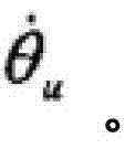
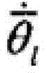
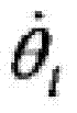
The modelling downhole parameters that rotatablely moves namely, is respectively that slender bodies is in the modelling estimated value of position, angle, angular velocity and the acceleration at down well placement place.
Usually, mark " u " (" on ") refers to pithead position, preferably the earth surface or near, and mark " l " refers to down well placement, preferably the downhole end place of slender bodies or near.Whippletree on the symbol refers to the modelling parameter.Point on the symbol refers to the time first derivative, and just, single-point is represented speed, and two point is represented acceleration.Subscript eq will be used for representing equilibrium valve, just, be used for the value of the non-vibrating state of system.
Angular velocity is also referred to as rotary speed.
In Fig. 1, the DRILL-STRING SYSTEM 10 with slender body extends downwardly into the wellhole from pithead position (such as big ground surface), and it is via 15 by drive system (motor 30) and driven, thereby has produced the driving torque T that is used for driving drill string
mThis motor 30 is controlled by controller 50 via 35.
Drive system generally includes rotating disk or top drive, and drill string typically comprises the bottom part (that is, bottom hole assemblies (BHA)) of having gained in weight, and it provides necessary the pressure of the drill during drilling well.
By top drive mean drive system thereon end (that is, near drill string from the suspended position of drilling well rig) drive drill string rotating.
The well head parameter of DRILL-STRING SYSTEM is determined such as locating on ground, and is used in the control strategy.
A well head parameter is relevant with the well head torque.Actual well head torque in the top part of drill string is T.In practice of the present invention, usually can obtain to be applied to the torque T in the modern driver (it is top drive normally)
mPerhaps with T
mDirectly related parameter is used as digital parameters.For the top drive that is directly connected to the drill string upper end, T and T
mVery big difference is not typically arranged, but at first can be thought identical haply.Small quantity variance can produce owing to the friction in the driver self and the high frequency that does not transmit between driver and drill string effect.In the rotating disk driver, can there be the difference that causes owing to transmission loss.Under any circumstance, well head torque T or the parameter directly related with this torque can by for example by the place, ground or near the residing torque sensor in field measure and determine.
Other well head parameters can be measured by suitable sensor.In this embodiment, well head speed
 The parameter that perhaps represents well head speed also by the place, ground or near sensor measurement.For example be a swing circle at pithead position place with the relevant parameter of well head speed.Swing circle and representation speed directly related with speed.
Control strategy also can adopt the modeling to well system.This model is represented with 70 in Fig. 1, and is typically implemented in the computer system of operating software (for example software of writing with Matlab).Known in the artly how to make up for given drill string and be used for the model of wellhole drill string.This model can be simple two-freedom (DOF) model, for example is similar to employed model in the 6.2.2 joint of Doris publication.This model can also be more complicated multiple degrees of freedom model.Also possible is to use original known Model Simplification Method to lead from many-DOF model and bear the 2-DOF model.Those skilled in the art know how to make up by the enough eigen modes that comprise well system the kinetic description of specific well system are got enough accurately to satisfy the model of controller needs.
Model 7 is via one or more well head parameters of 45 reception well systems or slender bodies.In this embodiment,
 In this embodiment as with
 Be input to the input parameter of the model of DRILL-STRING SYSTEM together.
 Be that controller begins to operate the estimated value of the position, angle of bottom hole assemblies constantly.Torque parameter also can be used as the input in the model, for example, and via 55 T that transmit
m
Be that controller begins to operate the estimated value of the position, angle of bottom hole assemblies constantly.Torque parameter also can be used as the input in the model, for example, and via 55 T that transmit
m
The model of DRILL-STRING SYSTEM can calculate the downhole parameters that rotatablely moves, for example
And/or
 And further calculate well head parameter and the downhole parameters of well system alternatively, such as, rotatablely move
 In these parameters some or all can be sent to controller 7 via 75, and at the controller place, they can be processed, for example has the multiplication routine (multiplication routine) of controller gain.In one embodiment,
 Be used as via 25 inputs for controller.This controller gain is can be for example determined in the 6.3.3 joint as the Doris publication.Based on the input that receives from
 controller 5, motor changes T with differential value-u
m, and it is supplied to DRILL-STRING SYSTEM 1, to suppress vibration.
Suitably, model also is used to determine the modelling torque
 This modelling torque is sent to
 comparator 90 via 82, it receives via 84 with the torque T(that is confirmed as the well head parameter at the comparator place) compare.If difference is less, prove that then well head torque T is lower by 10% than model, otherwise it is updated (represented by 86), till finding better uniformity.
Example
With reference to Fig. 2, discussed the 2-DOF model of well system 100.This system comprises two inertia (J
u, J
l), the flexible k of spring
θ, two friction torque (T
u, T
l) and from the driving torque of drive system, this drive system typically comprises electric notor (T
m).J
uBe the inertia of the top part of drive system (for example top drive) and drill string, J
lBe the inertia of the remainder of DHA (BHA) and drill string.k
θBe drilling rod rigidity, T
uTorque drag (electrostatic force in the motor, the friction in the ball bearing etc.) in the twist motion of drill string top part has been described, and T
lThe interaction of the drilling mud in BHA and stratum and drill string and the wellhole is on every side described.
Consider to describe the dynamic (dynamical) two groups of different equatioies of reversing of native system.
Equation (1)-(8) are considered to represent exactly DRILL-STRING SYSTEM, and are considered to the real system in this example.Model departs from real system usually.Therefore, in equation (9)-(10), some interference are added to k
θ, J
lAnd T
l, with the inaccuracy of simulation modelization.This interference value is usually less than 10% of a reference value.
The kinetics of the well system shown in Fig. 2 has been described in following equation (1)-(8).
As the modelling simulation of the well system shown in Fig. 2, following equation (9) and (10) are used for substituting (1) and (2).
Parameter in these equatioies (9,10) is in principle as equation (3)-8) in.T
LmHave and T
lIdentical structure that is to say, describe by equation (6)-(8), and in these equatioies T
ClmSubstituted T
ClAnd b
LmSubstituted b
l
When such as known from the ground survey result
 The time, people can with
 In equation (9) and (10), be replaced by
 Therefore, equation (9) can have following form:
In addition, because well head torque T is known or the measured fact
T=k
θ·(θ
u-θ
l) (13)
It can be compared with the torque that model calculates
So that whether the proof model can fully accurately describe the kinetics of DRILL-STRING SYSTEM.If
 And the difference between the T is greater than predetermined value, and for example greater than 10% of T, then model parameter is suitably further optimized, till between the model value that is used for well system and the actual value better matching being arranged.
Use Matlab software to calculate solve equation.In form 1, provide the parameter value of DRILL-STRING SYSTEM and model thereof.
Fig. 3 shows for well head torque T(301) and the torque of modelling well head
 (302) respectively as the result of the example of the function of time.This figure shows: when using in model
 The time, T with
 Mate very goodly.
In addition, depict θ at Fig. 4 (a) with 4(b)
u-θ
l(401),
 (402),
 (451) and
 (452) time curve.These accompanying drawings show θ
u-θ
lWith
(452) time curve.These accompanying drawings show θ
u-θ
lWith
 And
And
 With
With
 Mate very goodly.Glue-slide to clearly visible.In the reality, down-hole angular velocity
 Normally unavailable.What discuss and illustrate at this only is the ability of reversing dynamic (dynamical) model fully of verification model reconstruct DRILL-STRING SYSTEM, and does not need actual enforcement the present invention.
According to the present invention, be applied in to be used for carrying out torque control for the adjustment of driving torque, thus the control vibration.This adjustment can be taked the following form in this example:
Wherein, subscript eq referred to herein as the equilibrium valve of model and DRILL-STRING SYSTEM.This adjustment u is to use the modelling downhole parameters that rotatablely moves to calculate.
 With
With
 Equate, and they are DRILL-STRING SYSTEM desired values when drilling well, because when they equate, do not glue-slide vibration.In order to calculate
We have abandoned the component of acceleration in the equation (11) (12), we with
Equate, and they are DRILL-STRING SYSTEM desired values when drilling well, because when they equate, do not glue-slide vibration.In order to calculate
We have abandoned the component of acceleration in the equation (11) (12), we with
 Substitute, and we have found the solution equation (11) and (12) again.k
1, k
2, k
3The constant that is to use model (11), (12) to calculate according to the control theory of
Substitute, and we have found the solution equation (11) and (12) again.k
1, k
2, k
3The constant that is to use model (11), (12) to calculate according to the control theory of Doris publication.In form 1, provide their value.The total torque that is applied to DRILL-STRING SYSTEM is:
T
total=T
m-u (16)
Replace T
mBe that this torque is used in (1).
In Fig. 5 a and 5b, listed
 (501) and
 (551) closed loop result that is to say, in the time of in controller is comprised in according to the calculating of equation 14.This figure control loop of demonstrating out can be eliminated the sticking-sliding BHA vibration of DRILL-STRING SYSTEM.What note is that controller can be eliminated for very low RPM(revolutions per minute) sticking-sliding vibration, with respect to known sticking-sliding inhibition method, this is advantage, and has a great deal of practical meanings for the oil drilling system.
The present invention is not limited to its embodiment described above, wherein, can expect many modifications within the scope of the appended claims.The feature of corresponding embodiment for example can combine.


Claims (15)
Applications Claiming Priority (3)
| Application Number | Priority Date | Filing Date | Title |
|---|---|---|---|
| EP10196478 | 2010-12-22 | ||
| EP10196478.1 | 2010-12-22 | ||
| PCT/EP2011/073325 WO2012084886A1 (en) | 2010-12-22 | 2011-12-20 | Controlling vibrations in a drilling system |
Publications (2)
| Publication Number | Publication Date |
|---|---|
| CN103270243A true CN103270243A (en) | 2013-08-28 |
| CN103270243B CN103270243B (en) | 2016-07-06 |
Family
ID=44260410
Family Applications (1)
| Application Number | Title | Priority Date | Filing Date |
|---|---|---|---|
| CN201180061664.3A Expired - Fee Related CN103270243B (en) | 2010-12-22 | 2011-12-20 | Controlling Vibration in Drilling Systems |
Country Status (6)
| Country | Link |
|---|---|
| US (1) | US9482083B2 (en) |
| EP (1) | EP2655796A1 (en) |
| CN (1) | CN103270243B (en) |
| AU (2) | AU2011347490A1 (en) |
| CA (1) | CA2822344A1 (en) |
| WO (1) | WO2012084886A1 (en) |
Cited By (2)
| Publication number | Priority date | Publication date | Assignee | Title |
|---|---|---|---|---|
| CN106545327A (en) * | 2016-12-09 | 2017-03-29 | 北京四利通控制技术股份有限公司 | Intelligent driller's control system of rig |
| CN110067550A (en) * | 2019-01-23 | 2019-07-30 | 中国地质大学(武汉) | It is a kind of with multiple degrees of freedom-variable element DRILL-STRING SYSTEM rotary motion modeling method |
Families Citing this family (19)
| Publication number | Priority date | Publication date | Assignee | Title |
|---|---|---|---|---|
| BR112014009085A2 (en) * | 2011-10-14 | 2017-05-09 | Precision Energy Services Inc | drill string dynamics analysis using an angular rate sensor |
| NL2007656C2 (en) * | 2011-10-25 | 2013-05-01 | Cofely Experts B V | A method of and a device and an electronic controller for mitigating stick-slip oscillations in borehole equipment. |
| US20140318865A1 (en) * | 2011-11-25 | 2014-10-30 | Shell Internationale Research Maatschappij B.V. | Method and system for controlling vibrations in a drilling system |
| EP2976496B1 (en) | 2013-03-20 | 2017-06-28 | Schlumberger Technology B.V. | Drilling system control |
| US9650880B2 (en) * | 2013-04-12 | 2017-05-16 | Tesco Corporation | Waveform anti-stick slip system and method |
| US9657523B2 (en) * | 2013-05-17 | 2017-05-23 | Baker Hughes Incorporated | Bottomhole assembly design method to reduce rotational loads |
| US20170122092A1 (en) | 2015-11-04 | 2017-05-04 | Schlumberger Technology Corporation | Characterizing responses in a drilling system |
| US10100580B2 (en) | 2016-04-06 | 2018-10-16 | Baker Hughes, A Ge Company, Llc | Lateral motion control of drill strings |
| NL2016859B1 (en) * | 2016-05-30 | 2017-12-11 | Engie Electroproject B V | A method of and a device for estimating down hole speed and down hole torque of borehole drilling equipment while drilling, borehole equipment and a computer program product. |
| US11422999B2 (en) | 2017-07-17 | 2022-08-23 | Schlumberger Technology Corporation | System and method for using data with operation context |
| US10907463B2 (en) | 2017-09-12 | 2021-02-02 | Schlumberger Technology Corporation | Well construction control system |
| AR114505A1 (en) | 2018-01-05 | 2020-09-16 | Conocophillips Co | SYSTEM AND METHOD FOR ATTENUATING VIBRATION DUE TO BLOCKING AND SLIPPING |
| US11098573B2 (en) * | 2018-03-13 | 2021-08-24 | Nabors Drilling Technologies Usa, Inc. | Systems and methods for estimating drill bit rotational velocity using top drive torque and rotational velocity |
| US10890060B2 (en) | 2018-12-07 | 2021-01-12 | Schlumberger Technology Corporation | Zone management system and equipment interlocks |
| US10907466B2 (en) | 2018-12-07 | 2021-02-02 | Schlumberger Technology Corporation | Zone management system and equipment interlocks |
| US11655701B2 (en) | 2020-05-01 | 2023-05-23 | Baker Hughes Oilfield Operations Llc | Autonomous torque and drag monitoring |
| CN113638728B (en) * | 2021-08-05 | 2023-08-15 | 西南石油大学 | Super-deep well drilling column stick-slip vibration suppression method |
| CN113638729B (en) * | 2021-08-06 | 2023-08-04 | 西南石油大学 | Drill string stick-slip vibration suppression method considering torsion impactor |
| CN113738343B (en) * | 2021-09-16 | 2023-11-07 | 零空间(北京)科技有限公司 | VR underground drilling machine state detection method, system, device and equipment |
Citations (5)
| Publication number | Priority date | Publication date | Assignee | Title |
|---|---|---|---|---|
| CN1077774A (en) * | 1992-04-23 | 1993-10-27 | 长沙矿山研究院 | Microcomputer control system of rotary drill |
| CN2732995Y (en) * | 2004-09-16 | 2005-10-12 | 佛山市顺德区力源液压机械有限公司 | Automatic control system for hydraulic following screw pile |
| US20090229882A1 (en) * | 2008-03-17 | 2009-09-17 | Baker Hughes Incorporated | Distributed sensors-controller for active vibration damping from surface |
| CN101711304A (en) * | 2007-04-16 | 2010-05-19 | 海运控制公司 | System and method for testing a drilling control system |
| WO2010063982A1 (en) * | 2008-12-02 | 2010-06-10 | National Oilwell Varco, L.P. | Method and apparatus for reducing stick-slip |
Family Cites Families (7)
| Publication number | Priority date | Publication date | Assignee | Title |
|---|---|---|---|---|
| US4760735A (en) * | 1986-10-07 | 1988-08-02 | Anadrill, Inc. | Method and apparatus for investigating drag and torque loss in the drilling process |
| GB9003759D0 (en) | 1990-02-20 | 1990-04-18 | Shell Int Research | Method and system for controlling vibrations in borehole equipment |
| US6327539B1 (en) | 1998-09-09 | 2001-12-04 | Shell Oil Company | Method of determining drill string stiffness |
| US7748474B2 (en) * | 2006-06-20 | 2010-07-06 | Baker Hughes Incorporated | Active vibration control for subterranean drilling operations |
| US7775297B2 (en) * | 2006-12-06 | 2010-08-17 | Omron Oilfield & Marine, Inc. | Multiple input scaling autodriller |
| US8256534B2 (en) * | 2008-05-02 | 2012-09-04 | Baker Hughes Incorporated | Adaptive drilling control system |
| EP2549055B2 (en) * | 2008-12-02 | 2022-04-13 | National Oilwell Varco, L.P. | Method and apparatus for reducing stick-slip |
-
2011
- 2011-12-20 CA CA2822344A patent/CA2822344A1/en not_active Abandoned
- 2011-12-20 AU AU2011347490A patent/AU2011347490A1/en active Pending
- 2011-12-20 EP EP11802384.5A patent/EP2655796A1/en not_active Withdrawn
- 2011-12-20 AU AU2011101765A patent/AU2011101765A4/en not_active Ceased
- 2011-12-20 CN CN201180061664.3A patent/CN103270243B/en not_active Expired - Fee Related
- 2011-12-20 WO PCT/EP2011/073325 patent/WO2012084886A1/en not_active Ceased
- 2011-12-20 US US13/996,463 patent/US9482083B2/en not_active Expired - Fee Related
Patent Citations (5)
| Publication number | Priority date | Publication date | Assignee | Title |
|---|---|---|---|---|
| CN1077774A (en) * | 1992-04-23 | 1993-10-27 | 长沙矿山研究院 | Microcomputer control system of rotary drill |
| CN2732995Y (en) * | 2004-09-16 | 2005-10-12 | 佛山市顺德区力源液压机械有限公司 | Automatic control system for hydraulic following screw pile |
| CN101711304A (en) * | 2007-04-16 | 2010-05-19 | 海运控制公司 | System and method for testing a drilling control system |
| US20090229882A1 (en) * | 2008-03-17 | 2009-09-17 | Baker Hughes Incorporated | Distributed sensors-controller for active vibration damping from surface |
| WO2010063982A1 (en) * | 2008-12-02 | 2010-06-10 | National Oilwell Varco, L.P. | Method and apparatus for reducing stick-slip |
Cited By (4)
| Publication number | Priority date | Publication date | Assignee | Title |
|---|---|---|---|---|
| CN106545327A (en) * | 2016-12-09 | 2017-03-29 | 北京四利通控制技术股份有限公司 | Intelligent driller's control system of rig |
| CN106545327B (en) * | 2016-12-09 | 2017-11-28 | 北京四利通控制技术股份有限公司 | Intelligent driller's control system of rig |
| CN110067550A (en) * | 2019-01-23 | 2019-07-30 | 中国地质大学(武汉) | It is a kind of with multiple degrees of freedom-variable element DRILL-STRING SYSTEM rotary motion modeling method |
| CN110067550B (en) * | 2019-01-23 | 2020-05-01 | 中国地质大学(武汉) | Rotary motion modeling method of drill column system with multiple degrees of freedom and variable parameters |
Also Published As
| Publication number | Publication date |
|---|---|
| AU2011347490A1 (en) | 2013-06-20 |
| WO2012084886A1 (en) | 2012-06-28 |
| CA2822344A1 (en) | 2012-06-28 |
| EP2655796A1 (en) | 2013-10-30 |
| AU2011347490A2 (en) | 2015-12-10 |
| US9482083B2 (en) | 2016-11-01 |
| US20130277110A1 (en) | 2013-10-24 |
| CN103270243B (en) | 2016-07-06 |
| AU2011101765A4 (en) | 2016-02-25 |
Similar Documents
| Publication | Publication Date | Title |
|---|---|---|
| CN103270243A (en) | Controlling Vibration in Drilling Systems | |
| US10900288B2 (en) | Slide drilling system and method | |
| US8469117B2 (en) | Drill bits and methods of drilling curved boreholes | |
| US10724358B2 (en) | Anti-stick-slip systems and methods | |
| US10858927B2 (en) | Systems and methods for estimating forces on a drill bit | |
| US20140318865A1 (en) | Method and system for controlling vibrations in a drilling system | |
| WO2017132254A1 (en) | Model based testing of rotating borehole components | |
| Menand | Borehole tortuosity effect on maximum horizontal drilling length based on advanced buckling modeling | |
| Shor et al. | Drillstring vibration observation, modeling and prevention in the oil and gas industry | |
| US20180245403A1 (en) | Downhole turbine with an adjustable shroud | |
| CA2949671C (en) | System and method for controlled slip connection | |
| Nour et al. | Picking the optimum directional drilling technology (RSS vs PDM): A machine learning-based model | |
| Wang et al. | Theoretical study of tool-face disorientation mechanisms during slide drilling and correction by surface-rotation pulses | |
| CN116151101B (en) | A method for establishing a horizontal well drilling parameter optimization chart | |
| US11725499B2 (en) | Methods relating to tool face orientation | |
| Tikhonov et al. | Numerical simulation of well trajectory while drilling isotropic and anisotropic formations | |
| Sarker | Modeling and simulation of vibration in deviated wells | |
| Halafawi et al. | Complex BHA Mechanics and Performance Analysis for Horizontal Wells. | |
| Chewaroungroaj et al. | Well plan parameter guideline for directional drilling in the gulf of Thailand | |
| Zhang | Nonlinear drillstring dynamics: modeling, vibration analysis, and control | |
| Leonard | A first-principles directional drilling simulator for control design | |
| Sarker | Adaptive observer-based optimum tracking control design for the suppression of stick-slip and bit-bounce oscillations in drilling systems |
Legal Events
| Date | Code | Title | Description |
|---|---|---|---|
| C06 | Publication | ||
| PB01 | Publication | ||
| C10 | Entry into substantive examination | ||
| SE01 | Entry into force of request for substantive examination | ||
| C14 | Grant of patent or utility model | ||
| GR01 | Patent grant | ||
| CF01 | Termination of patent right due to non-payment of annual fee | ||
| CF01 | Termination of patent right due to non-payment of annual fee |
Granted publication date: 20160706 Termination date: 20211220 |