CN103168232A - Ultrasonic flaw detection device, ultrasonic transducer, and ultrasonic flaw detection method - Google Patents
Ultrasonic flaw detection device, ultrasonic transducer, and ultrasonic flaw detection method Download PDFInfo
- Publication number
- CN103168232A CN103168232A CN2011800503753A CN201180050375A CN103168232A CN 103168232 A CN103168232 A CN 103168232A CN 2011800503753 A CN2011800503753 A CN 2011800503753A CN 201180050375 A CN201180050375 A CN 201180050375A CN 103168232 A CN103168232 A CN 103168232A
- Authority
- CN
- China
- Prior art keywords
- laminated member
- oscillator
- ultrasonic
- transducer
- bend
- Prior art date
- Legal status (The legal status is an assumption and is not a legal conclusion. Google has not performed a legal analysis and makes no representation as to the accuracy of the status listed.)
- Granted
Links
Images


Classifications
-
- G—PHYSICS
- G01—MEASURING; TESTING
- G01N—INVESTIGATING OR ANALYSING MATERIALS BY DETERMINING THEIR CHEMICAL OR PHYSICAL PROPERTIES
- G01N29/00—Investigating or analysing materials by the use of ultrasonic, sonic or infrasonic waves; Visualisation of the interior of objects by transmitting ultrasonic or sonic waves through the object
- G01N29/22—Details, e.g. general constructional or apparatus details
- G01N29/225—Supports, positioning or alignment in moving situation
-
- G—PHYSICS
- G01—MEASURING; TESTING
- G01N—INVESTIGATING OR ANALYSING MATERIALS BY DETERMINING THEIR CHEMICAL OR PHYSICAL PROPERTIES
- G01N29/00—Investigating or analysing materials by the use of ultrasonic, sonic or infrasonic waves; Visualisation of the interior of objects by transmitting ultrasonic or sonic waves through the object
- G01N29/04—Analysing solids
- G01N29/043—Analysing solids in the interior, e.g. by shear waves
-
- G—PHYSICS
- G01—MEASURING; TESTING
- G01N—INVESTIGATING OR ANALYSING MATERIALS BY DETERMINING THEIR CHEMICAL OR PHYSICAL PROPERTIES
- G01N29/00—Investigating or analysing materials by the use of ultrasonic, sonic or infrasonic waves; Visualisation of the interior of objects by transmitting ultrasonic or sonic waves through the object
- G01N29/04—Analysing solids
- G01N29/06—Visualisation of the interior, e.g. acoustic microscopy
- G01N29/0654—Imaging
- G01N29/069—Defect imaging, localisation and sizing using, e.g. time of flight diffraction [TOFD], synthetic aperture focusing technique [SAFT], Amplituden-Laufzeit-Ortskurven [ALOK] technique
-
- G—PHYSICS
- G01—MEASURING; TESTING
- G01N—INVESTIGATING OR ANALYSING MATERIALS BY DETERMINING THEIR CHEMICAL OR PHYSICAL PROPERTIES
- G01N29/00—Investigating or analysing materials by the use of ultrasonic, sonic or infrasonic waves; Visualisation of the interior of objects by transmitting ultrasonic or sonic waves through the object
- G01N29/04—Analysing solids
- G01N29/07—Analysing solids by measuring propagation velocity or propagation time of acoustic waves
-
- G—PHYSICS
- G01—MEASURING; TESTING
- G01N—INVESTIGATING OR ANALYSING MATERIALS BY DETERMINING THEIR CHEMICAL OR PHYSICAL PROPERTIES
- G01N29/00—Investigating or analysing materials by the use of ultrasonic, sonic or infrasonic waves; Visualisation of the interior of objects by transmitting ultrasonic or sonic waves through the object
- G01N29/22—Details, e.g. general constructional or apparatus details
- G01N29/223—Supports, positioning or alignment in fixed situation
-
- G—PHYSICS
- G01—MEASURING; TESTING
- G01N—INVESTIGATING OR ANALYSING MATERIALS BY DETERMINING THEIR CHEMICAL OR PHYSICAL PROPERTIES
- G01N29/00—Investigating or analysing materials by the use of ultrasonic, sonic or infrasonic waves; Visualisation of the interior of objects by transmitting ultrasonic or sonic waves through the object
- G01N29/22—Details, e.g. general constructional or apparatus details
- G01N29/24—Probes
- G01N29/2456—Focusing probes
-
- G—PHYSICS
- G01—MEASURING; TESTING
- G01N—INVESTIGATING OR ANALYSING MATERIALS BY DETERMINING THEIR CHEMICAL OR PHYSICAL PROPERTIES
- G01N29/00—Investigating or analysing materials by the use of ultrasonic, sonic or infrasonic waves; Visualisation of the interior of objects by transmitting ultrasonic or sonic waves through the object
- G01N29/22—Details, e.g. general constructional or apparatus details
- G01N29/26—Arrangements for orientation or scanning by relative movement of the head and the sensor
- G01N29/262—Arrangements for orientation or scanning by relative movement of the head and the sensor by electronic orientation or focusing, e.g. with phased arrays
-
- G—PHYSICS
- G01—MEASURING; TESTING
- G01N—INVESTIGATING OR ANALYSING MATERIALS BY DETERMINING THEIR CHEMICAL OR PHYSICAL PROPERTIES
- G01N2291/00—Indexing codes associated with group G01N29/00
- G01N2291/02—Indexing codes associated with the analysed material
- G01N2291/023—Solids
- G01N2291/0231—Composite or layered materials
-
- G—PHYSICS
- G01—MEASURING; TESTING
- G01N—INVESTIGATING OR ANALYSING MATERIALS BY DETERMINING THEIR CHEMICAL OR PHYSICAL PROPERTIES
- G01N2291/00—Indexing codes associated with group G01N29/00
- G01N2291/10—Number of transducers
- G01N2291/106—Number of transducers one or more transducer arrays
-
- G—PHYSICS
- G01—MEASURING; TESTING
- G01N—INVESTIGATING OR ANALYSING MATERIALS BY DETERMINING THEIR CHEMICAL OR PHYSICAL PROPERTIES
- G01N2291/00—Indexing codes associated with group G01N29/00
- G01N2291/26—Scanned objects
- G01N2291/263—Surfaces
- G01N2291/2638—Complex surfaces
-
- G—PHYSICS
- G01—MEASURING; TESTING
- G01N—INVESTIGATING OR ANALYSING MATERIALS BY DETERMINING THEIR CHEMICAL OR PHYSICAL PROPERTIES
- G01N2291/00—Indexing codes associated with group G01N29/00
- G01N2291/26—Scanned objects
- G01N2291/269—Various geometry objects
- G01N2291/2694—Wings or other aircraft parts
Landscapes
- Physics & Mathematics (AREA)
- Health & Medical Sciences (AREA)
- Life Sciences & Earth Sciences (AREA)
- Chemical & Material Sciences (AREA)
- Analytical Chemistry (AREA)
- Biochemistry (AREA)
- General Health & Medical Sciences (AREA)
- General Physics & Mathematics (AREA)
- Immunology (AREA)
- Pathology (AREA)
- Acoustics & Sound (AREA)
- Investigating Or Analyzing Materials By The Use Of Ultrasonic Waves (AREA)
Abstract
Description
技术领域technical field
本发明涉及检查由复合材料形成的层叠部件的弯曲部的内部缺陷的状态的超声波探伤装置以及作为超声波探伤装置的主要构成要素的超声波换能器等。The present invention relates to an ultrasonic flaw detection device for inspecting the state of internal defects in a bent portion of a laminated member made of a composite material, an ultrasonic transducer as a main component of the ultrasonic flaw detection device, and the like.
背景技术Background technique
在检查由纤维强化复合材料(FRP)等复合材料形成的层叠部件的弯曲部中的内部缺陷的状态时,通常使用收发超声波的超声波换能器等。When inspecting the state of internal defects in bent portions of laminated parts made of composite materials such as fiber-reinforced composite materials (FRP), ultrasonic transducers or the like that transmit and receive ultrasonic waves are generally used.
超声波换能器具有换能器本体,该换能器本体在前端侧具有与在层叠部件的弯曲部的大径侧的曲面或小径侧的曲面对应的侧视弯曲形状的振动面。此外,在换能器本体的振动面上,沿着换能器本体的振动面的弯曲方面配置了多个振子,各振子向层叠部件的弯曲部侧发送超声波或者接收来自层叠部件的弯曲部侧的超声波,与控制单元电连接。The ultrasonic transducer has a transducer body having a vibrating surface having a curved surface in side view corresponding to a curved surface on a large-diameter side or a curved surface on a small-diameter side of a curved portion of a laminated member on the tip side. In addition, on the vibration surface of the transducer body, a plurality of vibrators are arranged along the curvature of the vibration surface of the transducer body. The ultrasonic wave is electrically connected with the control unit.
因此,在检查层叠部件的弯曲部中的内部缺陷的状态时,首先,使超声波换能器对于层叠部件相对移动,由此使换能器本体的振动面面向在层叠部件的弯曲部的大径侧的曲面或小径侧的曲面。然后,使从多个振子发送的超声波入射到层叠部件的弯曲部侧,通过多个振子从层叠部件的弯曲部侧接收反射波。由此,通过控制单元从多个振子根据接收信号(来自超声波换能器的探伤信号)能够非破坏性地检查层叠部件的弯曲部中的内部缺陷的状态。Therefore, when inspecting the state of the internal defect in the bent portion of the laminated component, first, the ultrasonic transducer is relatively moved with respect to the laminated component, whereby the vibrating surface of the transducer body faces the large diameter of the bent portion of the laminated component. The surface on the side or the surface on the side of the trail. Then, ultrasonic waves transmitted from the plurality of transducers are made incident on the bent portion side of the laminated member, and reflected waves are received from the bent portion side of the laminated member by the plurality of transducers. This makes it possible to non-destructively inspect the state of internal defects in the bent portion of the laminated member based on received signals (flaw detection signals from the ultrasonic transducer) from the plurality of vibrators by the control unit.
作为与本发明相关的现有技术等,例如存在日本专利公开公报特开2003-90829号以及特开平6-18488号。As prior art related to the present invention, there are, for example, Japanese Patent Laid-Open Publication Nos. 2003-90829 and 6-18488.
发明内容Contents of the invention
本发明要解决的课题Problems to be solved by the present invention
但是,当层叠部件的层数增加,层叠部件的弯曲部的厚度变厚时,反射波的超声波强度变小,通过超声波换能器难以充分地检查层叠部件的弯曲部中的内部缺陷的反射波。另一方面,当提高振子接收反射波的检测灵敏度时,噪音回波增大,从超声波换能器探伤信号(来自振子的接收信号)的SN比(缺陷回波的强度与噪音回波的强度比)降低。However, when the number of layers of the laminated part increases and the thickness of the bent part of the laminated part becomes thicker, the ultrasonic intensity of the reflected wave becomes smaller, and it is difficult to sufficiently inspect the reflected wave of an internal defect in the bent part of the laminated part by an ultrasonic transducer. . On the other hand, when the detection sensitivity of the vibrator to receive the reflected wave is increased, the noise echo increases, and the SN ratio (strength of the defect echo to the strength of the noise echo) of the ultrasonic transducer flaw detection signal (received signal from the vibrator) is increased. ratio) lower.
因此,当层叠部件的层数增加,层叠部件的弯曲部的厚度变厚时,存在难以提高层叠部件的弯曲部中的内部缺陷的检查精度的问题。Therefore, when the number of layers of the laminated member increases and the thickness of the bent portion of the laminated member becomes thicker, there is a problem that it is difficult to improve the inspection accuracy of internal defects in the bent portion of the laminated member.
根据本发明,可以提供SN比高探伤精度提高的超声波探伤装置以及超声波换能器等。According to the present invention, it is possible to provide an ultrasonic flaw detection device, an ultrasonic transducer, and the like with a high SN ratio and improved flaw detection accuracy.
用于解决课题的手段means to solve the problem
根据本发明的第一特征,检查由复合材料形成的层叠部件的弯曲部中的内部缺陷的状态的超声波探伤装置,具备:收发超声波的超声波换能器;以及根据来自所述超声波换能器的探伤信号(接收信号),进行所述层叠部件的所述弯曲部的所述内部缺陷的状态的检查处理的控制单元。更详细地说,所述超声波换能器具备:在前端侧具有与所述层叠部件的所述弯曲部中的大径侧的曲面或小径侧的曲面对应的侧视弯曲形状的振动面的换能器本体;以及在所述换能器本体的所述振动面上,在所述换能器本体的所述振动面的弯曲方向以及所述换能器本体的宽度方向上(换句话说,与所述触点本体的侧面正交的方向)矩阵状地配置的、向所述层叠部件的所述弯曲部侧发送超声波或者从所述层叠部件的所述弯曲部侧接收反射波的多个振子。所述控制单元在由在所述宽度方向上并排的多个所述振子构成的各振子组中,在根据预先设定的收发模式沿所述宽度方向切换发送用的所述振子以及接收用的所述振子的同时,根据来自接收用的所述振子的接收信号依次进行基于开口合成法的处理(接收信号的重合处理)。According to the first aspect of the present invention, an ultrasonic flaw detection device for inspecting the state of an internal defect in a bent portion of a laminated member formed of a composite material includes: an ultrasonic transducer for transmitting and receiving ultrasonic waves; A flaw detection signal (reception signal), a control unit that performs inspection processing of the state of the internal defect of the bent portion of the laminated component. More specifically, the ultrasonic transducer includes: a vibrating surface having a curved surface in side view corresponding to a curved surface on a large diameter side or a curved surface on a small diameter side in the curved portion of the laminated member on the distal end side. and on the vibrating surface of the transducer body, in the bending direction of the vibrating surface of the transducer body and in the width direction of the transducer body (in other words, a direction perpendicular to the side surface of the contact body) arranged in a matrix, and transmit ultrasonic waves to the side of the bent portion of the laminated member or receive reflected waves from the side of the bent portion of the laminated member Vibrator. The control unit switches the vibrator for transmission and the vibrator for reception in the width direction according to a preset transmission and reception pattern in each vibrator group composed of a plurality of vibrators arranged side by side in the width direction. Simultaneously with the transducers, processing based on the aperture synthesis method (superimposition processing of received signals) is sequentially performed on the basis of the reception signals from the reception transducers.
在此,在本发明的说明书以及权利要求书的记载中,“内部缺陷的状态”是包含内部缺陷的有无、内部缺陷的大小、内部缺陷的位置等的含义,“与曲面对应的侧视弯曲形状”是包含沿曲面的侧视弯曲形状、沿使曲面反转后的面的形状的含义。此外,“发送用所述振子”是为了发送超声波而选择的所述振子,“接收用的所述振子”是为了接收反射波而选择的所述振子。Here, in the specification and claims of the present invention, "the state of the internal defect" has the meaning including the presence or absence of the internal defect, the size of the internal defect, the position of the internal defect, etc., and "the side view corresponding to the curved surface The term "curved shape" includes a curved shape in side view along a curved surface and a shape along a reversed surface of the curved surface. In addition, "the transducer for transmission" is the transducer selected for transmitting ultrasonic waves, and the "transmitter for reception" is the transducer selected for receiving reflected waves.
根据本发明的第二特征,一种超声波换能器,其在检查由复合材料形成的层叠部件的弯曲部中的内部缺陷的状态时使用,收发超声波,该超声波换能器的特征在于,具备:在前端侧具有与所述层叠部件的所述弯曲部中的大径侧的曲面或小径侧的曲面对应的侧视弯曲形状的振动面的换能器本体;以及在所述换能器本体的所述振动面上,在所述换能器本体的所述振动面的弯曲方向以及所述换能器本体的宽度方向即与所述触点本体的侧面正交的方向上矩阵状地配置的、向所述层叠部件的所述弯曲部侧发送超声波或者从所述层叠部件的所述弯曲部侧接收反射波的多个振子。According to the second characteristic of the present invention, an ultrasonic transducer is used when inspecting the state of internal defects in a bent portion of a laminated component formed of a composite material, and transmits and receives ultrasonic waves, and the ultrasonic transducer is characterized in that it includes : a transducer body having a side-view curved vibrating surface corresponding to a curved surface on a large-diameter side or a curved surface on a small-diameter side of the curved portion of the laminated member at the front end; and the transducer body The vibration surface of the transducer body is arranged in a matrix in the bending direction of the vibration surface of the transducer body and the width direction of the transducer body, that is, the direction perpendicular to the side surface of the contact body a plurality of transducers for transmitting ultrasonic waves to the bent portion side of the laminated member or receiving reflected waves from the bent portion side of the laminated member.
根据本发明的第三特征,一种超声波探伤方法,其使用第二特征的超声波换能器,检查由复合材料形成的层叠部件的弯曲部中的内部缺陷的状态,所述超声波探伤方法的特征在于,包含以下步骤:使所述超声波换能器对于所述层叠部件相对移动,由此使所述换能器本体的所述振动面面向所述层叠部件的所述弯曲部中的大径侧的曲面或小径侧的曲面;在使音响介质介于所述层叠部件的所述弯曲部和所述超声波换能器之间的状态下,在由在所述宽度方向并排的多个所述振子构成的任意一个所述振子组中,在根据预先设定的收发模式沿着所述宽度方向切换发送用的所述振子以及接收用的所述振子的同时,使从发送用的所述振子发送的超声波射入所述层叠部件的所述弯曲部,通过接收用的所述振子从所述层叠部件的所述弯曲部侧接收反射波,从接收用的所述振子根据接收信号进行基于开口合成法的处理;在其他全部的所述振子组中,也沿所述宽度方向切换发送用的所述振子以及接收用的所述振子的同时,从接收用的所述振子根据接收信号依次进行基于开口合成法的处理,由此来检查所述层叠部件的所述弯曲部中的所述内部缺陷的状态。According to a third feature of the present invention, an ultrasonic flaw detection method for inspecting a state of an internal defect in a bent portion of a laminated member formed of a composite material using the ultrasonic transducer of the second feature, the ultrasonic flaw detection method is characterized in that wherein the method includes the step of relatively moving the ultrasonic transducer with respect to the laminated member so that the vibrating surface of the transducer body faces the large-diameter side of the curved portion of the laminated member. curved surface or a curved surface on the small diameter side; with the acoustic medium interposed between the curved portion of the laminated member and the ultrasonic transducer, a plurality of the vibrators arranged side by side in the width direction In any one of the vibrator groups configured, while switching the vibrator for transmission and the vibrator for reception along the width direction according to a preset transmission and reception mode, the slave vibrator for transmission transmits The ultrasonic wave is incident on the curved part of the laminated part, the reflected wave is received from the curved part side of the laminated part by the vibrator for reception, and aperture-based synthesis is performed from the received signal by the vibrator for reception. In all other groups of vibrators, the vibrator for transmission and the vibrator for reception are also switched along the width direction, and the vibrator for reception is sequentially performed based on the received signal. The processing of the opening synthesis method thereby inspects the state of the internal defect in the bent portion of the laminated component.
附图说明Description of drawings
图1是本发明实施方式的超声波探伤装置的控制框图。FIG. 1 is a control block diagram of an ultrasonic flaw detection device according to an embodiment of the present invention.
图2是本发明实施方式的超声波换能器的放大侧视图。Fig. 2 is an enlarged side view of the ultrasonic transducer according to the embodiment of the present invention.
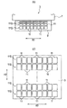
图3(a)是沿着图4(b)中的IIIB-IIIB线的图,图3(b)是将本发明实施方式的超声波换能器中的换能器本体的振动面展开为平面的图。Fig. 3(a) is a diagram along the line IIIB-IIIB in Fig. 4(b), and Fig. 3(b) expands the vibration surface of the transducer body in the ultrasonic transducer according to the embodiment of the present invention into a plane diagram.
图4(a)是本发明实施方式的超声波换能器的主视图,图4(b)是本发明实施方式的超声波换能器的侧视图。FIG. 4( a ) is a front view of the ultrasonic transducer according to the embodiment of the present invention, and FIG. 4( b ) is a side view of the ultrasonic transducer according to the embodiment of the present invention.
图5说明基于第1收发模式的发送用的压电振子以及接收用的压电振子的切换。FIG. 5 illustrates switching between the piezoelectric vibrator for transmission and the piezoelectric vibrator for reception based on the first transmission and reception mode.
图6说明基于第2收发模式的发送用的压电振子以及接收用的压电振子的切换。FIG. 6 illustrates switching of the piezoelectric vibrator for transmission and the piezoelectric vibrator for reception based on the second transmission and reception mode.
图7是表示本发明实施方式的超声波探伤装置的概要结构的立体图。7 is a perspective view showing a schematic configuration of an ultrasonic flaw detection device according to an embodiment of the present invention.
具体实施方式Detailed ways
参照图1至图7说明本发明的实施方式。Embodiments of the present invention will be described with reference to FIGS. 1 to 7 .
如图7所示,本发明的实施方式的超声波探伤装置1是检查由复合材料形成的层叠部件W的弯曲部Wc中的内部缺陷的状态的装置,具备:经由音响介质收发超声波S(参照图2)的超声波换能器3、根据来自该超声波换能器3的探伤信号,进行层叠部件W的弯曲部Wc的内部缺陷的状态的检查处理的控制单元5。在此,在本发明的实施方式中,层叠部件W是由纤维强化复合材料(FRP)构成的作为航空器部件的框体,层叠部件W的弯曲部Wc是框体的带有法兰的根部,音响介质M是水等液体或固体。As shown in FIG. 7 , an ultrasonic
本发明实施方式的超声波换能器3的具体结构如下那样。The specific structure of the
即,如图1至图4所示,超声波换能器3具备换能器本体7,该换能器本体7在前端侧具有沿着层叠部件W的弯曲部Wc中的大径侧的曲面的侧视弯曲形状的振动面9。换能器本体7还可以是与层叠部件W的弯曲部Wc中的小径侧的曲面对应的形状,来取代具有沿着层叠部件W的弯曲部Wc中的大径侧的曲面的侧视弯曲形状的振动面9。That is, as shown in FIGS. 1 to 4 , the
换能器本体7的振动面9上,在换能器本体7的振动面9的弯曲方向AD以及换能器本体7的宽度方向即与换能器本体7的侧面垂直的方向BD上矩阵状地配置多个(在本发明的实施方式中,为8×8个)压电振子11。各压电振子11向层叠部件W的弯曲部Wc侧发送超声波S,或者从层叠部件W的弯曲部Wc侧接收反射波S。此外,各压电振子11由复合材料或陶瓷材料构成,并与控制单元5连接。在本发明的实施方式中,通过在宽度方向BD上并排的8个压电振子11构成一个压电振子组11G,压电振子组11G的组数为8。On the vibrating
在换能器本体7内部,设置有吸收多个压电振子11的多余的振动的减振器(省略图示)。Inside the transducer
本发明实施方式的控制单元5的具体结构如下所述。The specific structure of the
如图1所示,控制单元5具有:向压电振子11供给驱动信号(发送信号)的信号生成部13以及对来自压电振子11的接收信号(来自超声波换能器3的探伤信号)进行放大的接收器15。并且,信号生成部13以及上述的多个压电振子11与切换电路17连接,该切换电路17能够将选择的压电振子11和信号生成部13切换为连接状态和切断状态。此外。接收器15以及上述多个压电振子11与信号检测电路19连接,该信号检测电路19能够把选择出的压电振子11和接收器15切换为连接状态和切断状态。As shown in FIG. 1 , the
具体地说,如图5所示,切换电路17根据预先设定的第一收发模式,沿宽度方向BD将各压电振子组11G中的发送用(T)的压电振子11划分为8阶段来进行切换。同样,信号检测电路19根据第一收发模式,沿宽度方向BD,将各压电振子组11G中的接收用(R)的压电振子11划分为8个阶段来进行切换。Specifically, as shown in FIG. 5 , the
此外,还可以取代基于第一收发模式,如图6所示,根据预先设定的第二收发模式,沿宽度方向BD把各压电振子组11G中的收发用的压电振子11(发送用的压电振子11以及接收用的压电振子11)划分为8个阶段来进行切换。在基于第二收发模式时,使发送用的压电振子11位于换能器本体7的振动面9中的宽度方向BD的中间区域内,接收用(R)的压电振子11从宽度方向BD的两侧间隔发送用(T)的压电振子11。In addition, instead of being based on the first transmitting and receiving mode, as shown in FIG. 6 , according to a preset second transmitting and receiving mode, the
在接收器15上连接信号处理部21,该信号处理部21在各压电振子组11G中,根据对接收用的压电振子11接收到的信号进行放大后的接收信号,依次进行基于开口合成法的处理(接收信号的重合处理)。此外,在基于开口合成法的处理时,使用超声波换能器3和层叠部件W的弯曲部Wc的位置关系、超声波换能器3的探伤频率、层叠部件W以及音响介质M中的音速等系统信息。并且,在信号处理部21上连接有结合显示信号处理部21的处理结果(开口合成图像等)和超声波换能器3的位置信息的显示部(省略图示)。The
包含作用在内说明本发明实施方式的超声波探伤方法。The ultrasonic flaw detection method according to the embodiment of the present invention will be described including its function.
使超声波换能器3相对于层叠部件W移动,由此使换能器本体7的振动面9面向层叠部件W的弯曲部Wc中的大径侧的曲面。然后,在使音响介质M介于层叠部件W的弯曲部Wc和超声波换能器3之间的状态下,使从发送用的压电振子11发送的超声波S射入层叠部件W的弯曲部Wc,通过接收用的压电振子11接收反射波S。更详细地说,通过切换电路17以及信号检测电路19根据第一收发模式或第二收发模式,沿着宽度方向BD把任意一个压电振子组11G中的收发用的压电振子11切换为8阶段或4阶段(参照图5以及图6)。在各阶段,使从发送用的压电振子11发送的超声波S射入层叠部件W的弯曲部Wc,通过接收用的压电振子11从层叠部件W的弯曲部Wc侧接收反射波S(参照图2)。然后,通过信号处理部21从任意一个压电振子组11G中的接收用的压电振子11,根据接收信号进行基于开口合成法的处理。By moving the
同样地,在其他全部的压电振子组11G中,也通过切换电路17以及信号检测电路19基于第一收发模式或第二收发模式,沿宽度方向BD将发送用的压电振子11切换为8阶段或4阶段的同时,通过信号处理部21从接收用的压电振子11根据接收信号依次进行基于开口合成法的处理。由此,对于层叠部件W的弯曲部Wc中的圆周方向的一部分区域,通过控制单元5能够进行内部缺陷的状态(内部缺陷的有无、内部缺陷的大小、内部缺陷的位置等)的检查处理(探伤处理),换句话说,能够检查(探伤)内部缺陷的状态。Similarly, in all the other
关于层叠部件W的弯曲部Wc中的圆周方向的一部分的检查区域,在检查到内部缺陷的状态后,使超声波换能器3相对于层叠部件W向圆周方向相对地移动,同时继续进行上述的处理,由此能够关于层叠部件W的弯曲部Wc中的圆周方向的全部区域,检查内部缺陷的状态。With regard to a part of the inspection area in the circumferential direction of the curved portion Wc of the laminated member W, after the state of internal defects is detected, the
简要地说,因为在换能器本体7的振动面9上在弯曲方向AD以及宽度方向BD上矩阵状地配置了多个压电振子11,所以能够在通过切换电路17以及信号检测电路19沿宽度方向BD切换各压电振子组11G中的收发用的压电振子11的同时,通过信号处理部21根据来自各压电振子组11G中的接收用的压电振子11的接收信号,进行基于开口合成法的处理。由此,即使层叠部件W的层数增加,层叠部件W的弯曲部Wc的厚度变厚,也不需要提高设定通过接收用的压电振子11接收的反射波S的检测灵敏度,可以通过超声波换能器3充分并且切实地检测层叠部件W的弯曲部Wc中的内部缺陷的反射波S。Briefly, since a plurality of
因此,根据本实施方式,即使层叠部件W的层数增加,层叠部件W的弯曲部Wc的厚度变厚,也可以降低噪音回波,提高来自超声波换能器3的探伤信号(来自接收用的压电振子11的接收信号)的SN比,提高层叠部件W的弯曲部Wc中的内部缺陷的状态的检查精度(探伤精度)。Therefore, according to this embodiment, even if the number of layers of the laminated member W increases and the thickness of the bent portion Wc of the laminated member W becomes thicker, noise echoes can be reduced and the flaw detection signal from the ultrasonic transducer 3 (from the receiving signal) can be improved. The S/N ratio of the received signal of the
特别是如图6所示,在基于第二收发模式时,可以限定超声波换能器3的检查范围(探伤范围),根据来自用于接收反射波S的接收用的压电振子11的接收信号,进行基于开口合成法的处理,能够进一步提高层叠部件W的弯曲部Wc中的内部缺陷的状态的检查精度。In particular, as shown in FIG. 6, when based on the second transmission and reception mode, the inspection range (flaw detection range) of the
如上所述,根据第一以及第二特征,使超声波换能器相对于层叠部件移动,由此使换能器本体的振动面面向层叠部件的弯曲部中的大径侧的曲面或小径侧的曲面。然后,在通过控制单元根据收发模式沿着所述超声波换能器的宽度方向切换任意一个振子组中的发送用的振子以及接收用的振子的同时,使从发送用的振子发送的超声波射入所述层叠部件的所述弯曲部,通过接收用的所述振子从所述层叠部件的所述弯曲部侧接收反射波。然后,通过所述控制单元从任意一个的所述振子组中的接收用的所述振子根据接收信号进行基于开口合成法的处理。同样地,在其他全部的所述振子组中,也在通过控制单元沿所述宽度方向切换发送用的所述振子以及接收用的所述振子的同时,从接收用的所述振子根据接收信号依次进行基于开口合成法的处理。由此能够通过控制单元进行所述层叠部件的所述弯曲部中的所述内部缺陷的状态的检查处理,换句话说,能够检查所述层叠部件的所述弯曲部中的所述内部缺陷的状态。As described above, according to the first and second features, the ultrasonic transducer is moved relative to the laminated member so that the vibrating surface of the transducer body faces the large-diameter curved surface or the small-diameter curved surface of the curved portion of the laminated member. surface. Then, while switching the transmitting transducer and the receiving transducer in any one of the transducer groups along the width direction of the ultrasonic transducer according to the transmitting and receiving mode, the ultrasonic wave transmitted from the transmitting transducer is injected. The bent portion of the laminated member receives reflected waves from the bent portion side of the laminated member through the vibrator for reception. Then, the receiving oscillator in any one of the oscillator groups performs processing based on the aperture synthesis method according to the received signal through the control unit. Similarly, in all other groups of transducers, the transducers for transmission and the transducers for reception are switched along the width direction by the control unit, and the transducers for reception receive signals from the transducers for reception. The processing based on the opening synthesis method is performed sequentially. Thereby, the inspection process of the state of the internal defect in the bent portion of the laminated member can be performed by the control unit, in other words, the state of the internal defect in the bent portion of the laminated member can be inspected. state.
简要地说,在上述超声波换能器中,在所述换能器本体的所述振动面上在所述弯曲方向以及所述宽度方向上矩阵状地配置了多个所述振子,所以能够在通过所述控制单元根据所述收发模式沿所述宽度方向切换各振子组中的收发用的所述振子以及接收用的所述振子的同时,从接收用的所述振子根据接收信号,依次进行基于开口合成法的处理。由此,即使所述层叠部件的层数增加,所述层叠部件的弯曲部的厚度变厚,也不需要提高设定通过接收用的所述振子接收的反射波的检测灵敏度,可以通过所述超声波换能器充分并且切实地检测到所述层叠部件的所述弯曲部中的所述内部缺陷引起的反射波。Briefly, in the above-mentioned ultrasonic transducer, a plurality of the vibrators are arranged in a matrix in the bending direction and the width direction on the vibrating surface of the transducer body, so it is possible to While the control unit switches the vibrator for transmitting and receiving and the vibrator for receiving in each vibrator group along the width direction according to the transceiving mode, the vibrator for receiving is sequentially performed according to the received signal. Processing based on opening synthesis. Therefore, even if the number of layers of the laminated member increases and the thickness of the bent portion of the laminated member becomes thicker, it is not necessary to increase the detection sensitivity of the reflected wave received by the receiving vibrator, and the The ultrasonic transducer sufficiently and reliably detects reflected waves caused by the internal defect in the bent portion of the laminated member.
根据本发明的第三特征是超声波换能器,因为在所述换能器本体的所述振动面上在所述弯曲方向以及所述宽度方向上矩阵状地设置了多个所述振子,所以如上所述,能够在通过所述控制单元根据所述收发模式沿所述宽度方向切换各振子组中的收发用的所述振子以及接收用的所述振子的同时,从接收用的所述振子根据接收信号,进行基于开口合成法的处理。由此,即使所述层叠部件的层数增加,所述层叠部件的弯曲部的厚度变厚,也不需要提高设定通过接收用的所述振子接收的反射波的检测灵敏度,可以通过所述超声波换能器充分并且切实地检测所述层叠部件的所述弯曲部中的所述内部缺陷的反射波。According to a third feature of the present invention, in the ultrasonic transducer, since a plurality of the vibrators are arranged in a matrix in the bending direction and the width direction on the vibrating surface of the transducer body, As described above, it is possible to switch from the receiving oscillator to the receiving oscillator while switching the transmitting and receiving oscillator and the receiving oscillator in each oscillator group in the width direction according to the transmitting and receiving mode. Based on the received signal, processing based on the aperture combining method is performed. Therefore, even if the number of layers of the laminated member increases and the thickness of the bent portion of the laminated member becomes thicker, it is not necessary to increase the detection sensitivity of the reflected wave received by the receiving vibrator, and the The ultrasonic transducer sufficiently and reliably detects the reflected wave of the internal defect in the bent portion of the laminated member.
根据本发明,即使所述层叠部件的层数增加,所述层叠部件的弯曲部的厚度变厚,也可以通过所述超声波换能器充分并且切实地检测所述层叠部件的所述弯曲部中的所述内部缺陷的反射波,所以能够降低噪音回波,提高来自所述超声波换能器的探伤信号的SN比,提高所述层叠部件的所述弯曲部中的所述内部缺陷的状态的检查精度。According to the present invention, even if the number of layers of the laminated member increases and the thickness of the bent portion of the laminated member becomes thicker, the ultrasonic transducer can sufficiently and reliably detect the thickness of the curved portion of the laminated member. Reflected waves of the internal defect, so noise echo can be reduced, the S/N ratio of the flaw detection signal from the ultrasonic transducer can be improved, and the state of the internal defect in the bent portion of the laminated member can be improved. Check the precision.
本发明不限于上述实施方式的说明,能够通过各种方式来实施。本发明包含的权利要求范围不限于这些实施方式。The present invention is not limited to the description of the above-mentioned embodiments, and can be implemented in various forms. The scope of claims encompassed by the present invention is not limited to these embodiments.
(美国指定)(US designation)
本国际申请针对美国指定,关于在2010年10月22日申请的日本专利申请No.2010-237649号(2010年10月22日申请),基于美国专利法第119条(a)享受基于优先权的好处;其全部内容被收容于本申请中,以资参考。This international application is designated for the United States, and enjoys priority based on Section 119(a) of the U.S. Patent Law regarding Japanese Patent Application No. 2010-237649 (filed on October 22, 2010) filed on October 22, 2010 benefits; its entire contents are incorporated in this application by reference.
Claims (8)
Applications Claiming Priority (3)
| Application Number | Priority Date | Filing Date | Title |
|---|---|---|---|
| JP2010-237649 | 2010-10-22 | ||
| JP2010237649A JP5986709B2 (en) | 2010-10-22 | 2010-10-22 | Ultrasonic flaw detection apparatus and ultrasonic flaw detection method |
| PCT/JP2011/074303 WO2012053639A1 (en) | 2010-10-22 | 2011-10-21 | Ultrasonic flaw detection device, ultrasonic transducer, and ultrasonic flaw detection method |
Publications (2)
| Publication Number | Publication Date |
|---|---|
| CN103168232A true CN103168232A (en) | 2013-06-19 |
| CN103168232B CN103168232B (en) | 2015-05-27 |
Family
ID=45975346
Family Applications (1)
| Application Number | Title | Priority Date | Filing Date |
|---|---|---|---|
| CN201180050375.3A Expired - Fee Related CN103168232B (en) | 2010-10-22 | 2011-10-21 | Ultrasonic flaw detection device, ultrasonic transducer, and ultrasonic flaw detection method |
Country Status (7)
| Country | Link |
|---|---|
| US (1) | US9719966B2 (en) |
| EP (1) | EP2631641B1 (en) |
| JP (1) | JP5986709B2 (en) |
| CN (1) | CN103168232B (en) |
| CA (1) | CA2814939C (en) |
| RU (1) | RU2539806C2 (en) |
| WO (1) | WO2012053639A1 (en) |
Cited By (2)
| Publication number | Priority date | Publication date | Assignee | Title |
|---|---|---|---|---|
| CN103977949A (en) * | 2014-05-30 | 2014-08-13 | 北京理工大学 | Flexible comb-shaped guided wave phased array transducer |
| CN103990592A (en) * | 2014-05-30 | 2014-08-20 | 北京理工大学 | Flexible comb-shaped wave guiding transducer suitable for curved plate tubing part detecting |
Families Citing this family (8)
| Publication number | Priority date | Publication date | Assignee | Title |
|---|---|---|---|---|
| US9395335B2 (en) * | 2013-07-15 | 2016-07-19 | The Boeing Company | Ultrasonic inspection system for non-planar surfaces |
| JP2015075360A (en) * | 2013-10-07 | 2015-04-20 | 三菱重工業株式会社 | Probe, ultrasonic flaw detection device and ultrasonic flaw detection control method |
| JP2015190955A (en) * | 2014-03-28 | 2015-11-02 | 出光興産株式会社 | FRP intensity diagnostic apparatus and FRP intensity diagnostic method using the same |
| US10126122B2 (en) * | 2016-04-14 | 2018-11-13 | The Boeing Company | Ultrasonic inspection of wrinkles in composite objects |
| RU2650711C1 (en) * | 2017-05-23 | 2018-04-17 | Акционерное общество "Центральный научно-исследовательский институт специального машиностроения" (АО "ЦНИИСМ") | Method for determining depth of defects in products from composite materials |
| RU175588U1 (en) * | 2017-06-16 | 2017-12-11 | Закрытое акционерное общество "Ультракрафт" | Modular ultrasonic transducer for non-destructive testing |
| JP7145799B2 (en) * | 2019-03-19 | 2022-10-03 | 株式会社東芝 | ultrasonic inspection equipment |
| JP7495725B2 (en) * | 2020-08-06 | 2024-06-05 | 国立大学法人愛媛大学 | Apparatus, method, and program for ultrasonic imaging inside road pavement |
Citations (8)
| Publication number | Priority date | Publication date | Assignee | Title |
|---|---|---|---|---|
| JPS5775640A (en) * | 1980-10-29 | 1982-05-12 | Hitachi Ltd | Ultrasonic shotographing apparatus |
| JPH0618488A (en) * | 1992-07-06 | 1994-01-25 | Mitsubishi Heavy Ind Ltd | Ultrasonic inspecting method for composite material |
| JP2003090829A (en) * | 2001-09-18 | 2003-03-28 | Mitsubishi Heavy Ind Ltd | Non-destructive inspection method of composite material |
| CN1809748A (en) * | 2003-06-17 | 2006-07-26 | 株式会社东芝 | 3-dimensional ultrasonographic device |
| JP2007192649A (en) * | 2006-01-19 | 2007-08-02 | Toshiba Corp | 3D ultrasonic inspection equipment |
| CN101352354A (en) * | 2007-07-27 | 2009-01-28 | 株式会社东芝 | Ultrasonic diagnostic device |
| EP2182352A2 (en) * | 2008-10-29 | 2010-05-05 | Hitachi Ltd. | Apparatus and method for ultrasonic testing |
| CN101852773A (en) * | 2009-03-30 | 2010-10-06 | 株式会社东芝 | Ultrasonic imaging apparatus |
Family Cites Families (19)
| Publication number | Priority date | Publication date | Assignee | Title |
|---|---|---|---|---|
| DE2349294A1 (en) | 1972-10-04 | 1974-04-11 | Brulfert | STEAM OR HOT WATER GENERATOR WITH CATALYTIC BURNING OF HYDROCARBONS |
| SU896545A1 (en) * | 1977-08-08 | 1982-01-07 | Предприятие П/Я А-3724 | Ultrasonic detector |
| JPS5817361A (en) * | 1981-07-24 | 1983-02-01 | Aloka Co Ltd | Ultrasonic probe |
| JPH0618488B2 (en) | 1984-01-31 | 1994-03-16 | 井関農機株式会社 | Combine with seeding device |
| JPS6196454A (en) * | 1984-10-17 | 1986-05-15 | Toshiba Corp | Ultrasonic video device |
| US5269309A (en) * | 1991-12-11 | 1993-12-14 | Fort J Robert | Synthetic aperture ultrasound imaging system |
| JPH06339479A (en) * | 1993-06-01 | 1994-12-13 | Hitachi Medical Corp | Ultrasonic diagnostic device |
| JPH09154844A (en) * | 1995-12-12 | 1997-06-17 | Hitachi Medical Corp | Ultrasonic diagnostic device |
| JP3664826B2 (en) * | 1996-11-08 | 2005-06-29 | 三菱電機株式会社 | Ultrasonic flaw detector |
| AU3208299A (en) * | 1998-03-26 | 1999-10-18 | Exogen, Inc. | Arrays made from flexible transducer elements |
| US6813950B2 (en) * | 2002-07-25 | 2004-11-09 | R/D Tech Inc. | Phased array ultrasonic NDT system for tubes and pipes |
| JP4322620B2 (en) * | 2003-06-17 | 2009-09-02 | 株式会社東芝 | 3D ultrasonic imaging device |
| JP4426478B2 (en) * | 2005-02-18 | 2010-03-03 | アロカ株式会社 | Ultrasonic diagnostic equipment |
| DE102006010010A1 (en) * | 2006-03-04 | 2007-09-06 | Intelligendt Systems & Services Gmbh & Co Kg | Method for ultrasonic testing of a workpiece in a curved area of its surface and suitable test arrangement for carrying out the method |
| US7836768B2 (en) * | 2008-02-27 | 2010-11-23 | The Boeing Company | Ultrasonic testing of corner radii having different angles and sizes |
| US8250928B2 (en) * | 2008-07-09 | 2012-08-28 | The Boeing Company | Measurement of strain in an adhesively bonded joint including magnetostrictive material |
| JP5183422B2 (en) * | 2008-10-29 | 2013-04-17 | 株式会社日立製作所 | Three-dimensional ultrasonic imaging method and apparatus |
| JP5333261B2 (en) | 2009-03-11 | 2013-11-06 | Jsr株式会社 | Polarization diffraction element |
| US8408065B2 (en) * | 2009-03-18 | 2013-04-02 | Bp Corporation North America Inc. | Dry-coupled permanently installed ultrasonic sensor linear array |
-
2010
- 2010-10-22 JP JP2010237649A patent/JP5986709B2/en active Active
-
2011
- 2011-10-21 CN CN201180050375.3A patent/CN103168232B/en not_active Expired - Fee Related
- 2011-10-21 RU RU2013122839/28A patent/RU2539806C2/en active
- 2011-10-21 CA CA2814939A patent/CA2814939C/en active Active
- 2011-10-21 WO PCT/JP2011/074303 patent/WO2012053639A1/en not_active Ceased
- 2011-10-21 EP EP11834478.7A patent/EP2631641B1/en active Active
-
2013
- 2013-11-29 US US14/093,166 patent/US9719966B2/en active Active
Patent Citations (8)
| Publication number | Priority date | Publication date | Assignee | Title |
|---|---|---|---|---|
| JPS5775640A (en) * | 1980-10-29 | 1982-05-12 | Hitachi Ltd | Ultrasonic shotographing apparatus |
| JPH0618488A (en) * | 1992-07-06 | 1994-01-25 | Mitsubishi Heavy Ind Ltd | Ultrasonic inspecting method for composite material |
| JP2003090829A (en) * | 2001-09-18 | 2003-03-28 | Mitsubishi Heavy Ind Ltd | Non-destructive inspection method of composite material |
| CN1809748A (en) * | 2003-06-17 | 2006-07-26 | 株式会社东芝 | 3-dimensional ultrasonographic device |
| JP2007192649A (en) * | 2006-01-19 | 2007-08-02 | Toshiba Corp | 3D ultrasonic inspection equipment |
| CN101352354A (en) * | 2007-07-27 | 2009-01-28 | 株式会社东芝 | Ultrasonic diagnostic device |
| EP2182352A2 (en) * | 2008-10-29 | 2010-05-05 | Hitachi Ltd. | Apparatus and method for ultrasonic testing |
| CN101852773A (en) * | 2009-03-30 | 2010-10-06 | 株式会社东芝 | Ultrasonic imaging apparatus |
Cited By (2)
| Publication number | Priority date | Publication date | Assignee | Title |
|---|---|---|---|---|
| CN103977949A (en) * | 2014-05-30 | 2014-08-13 | 北京理工大学 | Flexible comb-shaped guided wave phased array transducer |
| CN103990592A (en) * | 2014-05-30 | 2014-08-20 | 北京理工大学 | Flexible comb-shaped wave guiding transducer suitable for curved plate tubing part detecting |
Also Published As
| Publication number | Publication date |
|---|---|
| US9719966B2 (en) | 2017-08-01 |
| JP2012088282A (en) | 2012-05-10 |
| EP2631641B1 (en) | 2020-02-19 |
| CA2814939A1 (en) | 2012-04-26 |
| RU2013122839A (en) | 2014-12-10 |
| CA2814939C (en) | 2017-10-24 |
| US20140083193A1 (en) | 2014-03-27 |
| WO2012053639A1 (en) | 2012-04-26 |
| JP5986709B2 (en) | 2016-09-06 |
| RU2539806C2 (en) | 2015-01-27 |
| EP2631641A4 (en) | 2016-06-22 |
| EP2631641A1 (en) | 2013-08-28 |
| CN103168232B (en) | 2015-05-27 |
Similar Documents
| Publication | Publication Date | Title |
|---|---|---|
| CN103168232B (en) | Ultrasonic flaw detection device, ultrasonic transducer, and ultrasonic flaw detection method | |
| US9310339B2 (en) | Hybrid inspection system and method employing both air-coupled and liquid-coupled transducers | |
| EP3070467B1 (en) | Ultrasonic test system, ultrasonic test method and method of manufacturing aircraft part | |
| EP3405782B1 (en) | Inspection devices and related systems and methods | |
| EP0878691A1 (en) | A device for ultrasonic inspection of a multi-layer metal workpiece | |
| WO2007113907A1 (en) | Ultrasonic probe, ultrasonic flaw detection method and ultrasonic flaw detection device | |
| CN107735680B (en) | The removing inspection method and removing check device of laminated body | |
| CN106990172A (en) | A kind of ultrasound detection and imaging method and its system | |
| HK1245403A1 (en) | Laminated body peeling examination method and peeling examination device | |
| CN113874721B (en) | A method and device for non-destructive testing of plate materials | |
| JP2007192649A (en) | 3D ultrasonic inspection equipment | |
| US20110126628A1 (en) | Non-destructive ultrasound inspection with coupling check | |
| KR20130080084A (en) | An polymer material based flexible phased array ultrasonic transducer for ultrasonic nondestructive testing of material with uneven surface | |
| EP3722802B1 (en) | Multi-functional ultrasonic phased array imaging device | |
| Vladišauskas et al. | Contact ultrasonic transducers for mechanical scanning systems | |
| WO2019150953A1 (en) | Ultrasonic probe | |
| KR101558921B1 (en) | Dual type ultrasonic sensor for adjusting focal length | |
| Hillger et al. | Impact Detection in a Composite Tail Boom Structure with Ultrasonic Imaging and Guided Waves Techniques | |
| JP2008510977A (en) | System for forming ultrasound images by transmission using at least one piezoelectric film | |
| Bellan et al. | REVIEW OF NON DESTRUCTIVE TESTING TECHNIQUES FOR COMPOSITES MATERIALS AND NEW APPLICATIONS OF PIEZO-POLYMER INTERDIGITAL TRANSDUCERS | |
| Chandrasekaran | Air-Coupled Ultrasonic Testing of Composite Materials | |
| JP2008070189A (en) | Ultrasonic flaw detection method and ultrasonic flaw detection apparatus |
Legal Events
| Date | Code | Title | Description |
|---|---|---|---|
| C06 | Publication | ||
| PB01 | Publication | ||
| C10 | Entry into substantive examination | ||
| SE01 | Entry into force of request for substantive examination | ||
| C14 | Grant of patent or utility model | ||
| GR01 | Patent grant | ||
| CF01 | Termination of patent right due to non-payment of annual fee | ||
| CF01 | Termination of patent right due to non-payment of annual fee |
Granted publication date: 20150527 |