CN103158631A - Switch module built in steering wheel - Google Patents
Switch module built in steering wheel Download PDFInfo
- Publication number
- CN103158631A CN103158631A CN2012102232428A CN201210223242A CN103158631A CN 103158631 A CN103158631 A CN 103158631A CN 2012102232428 A CN2012102232428 A CN 2012102232428A CN 201210223242 A CN201210223242 A CN 201210223242A CN 103158631 A CN103158631 A CN 103158631A
- Authority
- CN
- China
- Prior art keywords
- switch module
- fixed block
- removable
- input
- module
- Prior art date
- Legal status (The legal status is an assumption and is not a legal conclusion. Google has not performed a legal analysis and makes no representation as to the accuracy of the status listed.)
- Granted
Links
- 230000033001 locomotion Effects 0.000 claims abstract description 7
- 239000000463 material Substances 0.000 claims description 5
- 238000001816 cooling Methods 0.000 claims 1
- 238000010438 heat treatment Methods 0.000 claims 1
- 230000006870 function Effects 0.000 description 8
- 230000008878 coupling Effects 0.000 description 3
- 238000010168 coupling process Methods 0.000 description 3
- 238000005859 coupling reaction Methods 0.000 description 3
- 238000010586 diagram Methods 0.000 description 2
- 239000000446 fuel Substances 0.000 description 2
- 230000035807 sensation Effects 0.000 description 2
- 230000005540 biological transmission Effects 0.000 description 1
- 230000002950 deficient Effects 0.000 description 1
- 230000000694 effects Effects 0.000 description 1
- 238000005516 engineering process Methods 0.000 description 1
- 238000009434 installation Methods 0.000 description 1
- 230000001737 promoting effect Effects 0.000 description 1
- 239000007858 starting material Substances 0.000 description 1
- 239000000126 substance Substances 0.000 description 1
Images


Classifications
-
- H—ELECTRICITY
- H01—ELECTRIC ELEMENTS
- H01H—ELECTRIC SWITCHES; RELAYS; SELECTORS; EMERGENCY PROTECTIVE DEVICES
- H01H25/00—Switches with compound movement of handle or other operating part
-
- B—PERFORMING OPERATIONS; TRANSPORTING
- B60—VEHICLES IN GENERAL
- B60R—VEHICLES, VEHICLE FITTINGS, OR VEHICLE PARTS, NOT OTHERWISE PROVIDED FOR
- B60R16/00—Electric or fluid circuits specially adapted for vehicles and not otherwise provided for; Arrangement of elements of electric or fluid circuits specially adapted for vehicles and not otherwise provided for
- B60R16/02—Electric or fluid circuits specially adapted for vehicles and not otherwise provided for; Arrangement of elements of electric or fluid circuits specially adapted for vehicles and not otherwise provided for electric constitutive elements
-
- B—PERFORMING OPERATIONS; TRANSPORTING
- B62—LAND VEHICLES FOR TRAVELLING OTHERWISE THAN ON RAILS
- B62D—MOTOR VEHICLES; TRAILERS
- B62D1/00—Steering controls, i.e. means for initiating a change of direction of the vehicle
- B62D1/02—Steering controls, i.e. means for initiating a change of direction of the vehicle vehicle-mounted
- B62D1/04—Hand wheels
-
- H—ELECTRICITY
- H01—ELECTRIC ELEMENTS
- H01H—ELECTRIC SWITCHES; RELAYS; SELECTORS; EMERGENCY PROTECTIVE DEVICES
- H01H3/00—Mechanisms for operating contacts
- H01H2003/008—Mechanisms for operating contacts with a haptic or a tactile feedback controlled by electrical means, e.g. a motor or magnetofriction
-
- H—ELECTRICITY
- H01—ELECTRIC ELEMENTS
- H01H—ELECTRIC SWITCHES; RELAYS; SELECTORS; EMERGENCY PROTECTIVE DEVICES
- H01H2215/00—Tactile feedback
- H01H2215/03—Sound
Landscapes
- Engineering & Computer Science (AREA)
- Mechanical Engineering (AREA)
- Chemical & Material Sciences (AREA)
- Combustion & Propulsion (AREA)
- Transportation (AREA)
- Steering Controls (AREA)
- Mechanical Control Devices (AREA)
- Push-Button Switches (AREA)
Abstract
The invention relates to a switch module located within a steering wheel of a vehicle, which includes an input switch module, a feedback module, and a controller. The input switch module allows a driver to conduct a variety of switching operations by, for example, pressing the left, right, front, or back of the steering wheel, or by making a leftward or rightward torsional motion or a leftward or rightward diagonal motion with respect to the steering wheel. The switch module controller receives inputs from the input switch module that correlate to these switching operations, and outputs a signal to a vehicle device such as, for example, a head up display, and also to a feedback module, which provides a feedback response to the driver confirming the switching operation. The present invention allows the driver to control vehicle devices and systems while maintaining contact with the steering wheel, thereby improving vehicle safety.
Description
Technical field
The present invention relates to a kind of switch module that is arranged in bearing circle.More particularly, the present invention relates to a kind of like this switch module, wherein input switch module and feedback module are combined and be arranged in bearing circle, make the driver can carry out switching manipulation when holding bearing circle.
Background technology
Bearing circle is designed to control the direction of vehicle, generally include toroidal assurance section, be installed on the air bag module in the inside diameter of assurance section, and loudspeaker.Various switches are installed around assurance section or the air bag module of bearing circle usually, to carry out various vehicle functions, and for example audio frequency, video and navigation (AVN), head-up display (HUD), etc.
The switch of prior art usually less and with more complicated mode be arranged in bearing circle assurance section around; Therefore have very large defective, the assurance section that namely needs the driver to unclamp bearing circle comes operating switch, thereby produces dangerous, unsafe driving condition.In addition, the switch of prior art is disadvantageous, because its small size and complicated layout have increased the possibility that the driver is not intended to touch wrong switch.
In view of the above problems, clearly need a kind of switch, when it allows the driver that the assurance section of hand and bearing circle is kept stable the contact, vehicles such as AVN, HUD of permission driver control function.
Summary of the invention
The invention provides a kind of switch module that is arranged in bearing circle.This switch module comprises input switch module and feedback module.The input switch module comprises power/torque sensor, works by receiving from torque operation power such as driver's grip or torsion.Feedback module is by providing feedback-induced (for example aud. snl. or vibration) to work to the driver, thereby allows the driver to confirm that switching function starts.In the time of in switch module is installed in bearing circle, the switching manipulation of input switch module can be performed by driver's various motion, for example, when contacting between the hand that keeps the driver and bearing circle, press forward or backward bearing circle or twist to the left or to the right bearing circle.
An aspect, the invention provides a kind of switch module that is installed in bearing circle assurance section, it comprises the input switch module, it has by the power/torque sensor of 7 kinds of motion action totally, and these actions comprise: push away or pull work, of short duration action, the twisting action and at the jackknife action of left or right diagonal to the left or to the right pressed.In addition, this switch module comprises feedback module, and being used for provides feedback-induced (for example aud. snl. or vibration) to the driver.
In an illustrative embodiments, the switch module that is arranged in bearing circle assurance section according to the present invention also comprises controller, and it comes the operational feedback module by detecting the output signal relevant to the operation of input switch module.
In another illustrative embodiments, the input switch module comprises: the first fixed block that is fixed in the first cross-sectional plane of bearing circle assurance section; Removable, reverse ground, be installed on the first fixed block movably; Be fixed in the second fixed block of the second cross-sectional plane of bearing circle assurance section; Six axle power/torque sensors, removable with the second fixed block between and be connected with them; And a plurality of input links, be connected in the outside face of removable and the second fixed block, be used for providing power or moment of torsion to six axle power/torque sensors.First, second transversal section is across internal diameter and the external diameter of (span) bearing circle, and separate with the first and second fixed blocks between distance corresponding circumferential distance roughly.
In another illustrative embodiments, the conjugant (bonding substance) with flexible material is sandwiched between the first fixed block and removable.
In another illustrative embodiments, input link can comprise a pair of articulated element and an elastic component, and wherein this first end to articulated element is pivotally connected in the groove that the outside face that is formed at removable forms; And this second end to articulated element is pivotally connected to the first end in elastic component, and the second end of elastic component is fixed in the outside face of the second fixed block.
In an illustrative embodiments that also has, removable of the input switch module and the second fixed block are connected to each other integratedly by contiguous block, and feedback module is installed in contiguous block.
In another illustrative embodiments, feedback module is packed in position near the bearing circle assurance section of input switch module individually.
In another illustrative embodiments, feedback module is utilized into vibrating motor, is vibrated when receiving the operation signal of self-controller.
According to the present invention, input switch module with power/torque sensor and feedback module can be installed in bearing circle, make the operation of the input switch module of installing to be carried out by a plurality of drivers' action, for example, press forward or backward bearing circle, perhaps torsional direction dish to the left or to the right.Therefore, the present invention makes driver's easy operating input switch module when the assurance section with bearing circle keeps in touch, thereby makes the driver keep safety control to vehicle.In addition, due to a plurality of switches (for example, AVN, HUD etc.) can be installed in an input switch module, therefore the present invention can be easy to and operate safely all switches, pass through simultaneously to remove typically great quantity of small and the switch of arrangement torpidly in prior art, and clean and tidy outward appearance is provided.
In addition, should be appreciated that, because after switching manipulation has been imported into the input switch module, just carry out from the vibration of feedback module output, so the driver can the search switch operation completes.
Description of drawings
Next, describe above-mentioned and further feature of the present invention in detail with reference to the specific implementations shown in accompanying drawing, the effect of explaination is only played in these explanations, therefore is not limited to the present invention, wherein:
Fig. 1 is the block diagram that illustrates according to input switch module of the present invention;
Fig. 2 is the schematic diagram that the input switch module is positioned at an exemplary installation site of bearing circle according to the present invention;
Fig. 3 is the section drawing that the input switch module is positioned at an illustrative embodiments of bearing circle according to the present invention; And
Figure 4 and 5 are the section drawings that are arranged on the operation embodiment of the switch module in bearing circle according to the present invention.
The specific embodiment
Hereinafter will describe some embodiments of the present invention in detail, explain its example at accompanying drawing with in hereinafter describing.Although will describe the present invention in conjunction with the specific embodiment, be understandable that, this specification sheets and being not used in limits the present invention in these specific embodiment.On the contrary, the present invention not only covers these embodiments, but also cover a plurality ofly substitute, revise, of equal value and other embodiment, it is included in as defined by the appended claims in the spirit and scope of the present invention.
Be understandable that, term " vehicle " or " vehicle " or other similar term comprise power actuated vehicle as used herein, for example: comprise the person-carrying vehicle of sport utility vehicle (SUV), bus, multiple commercial vehicle, the ship that comprises multiple ship and warship, aircraft and similar, and comprise motor vehicle driven by mixed power, elec. vehicle, plug-in hybrid electric vehicles, hydrogen-powered vehicle and other alternative fuel vehicle (fuel that for example, obtains from oil resource in addition).As mentioned herein, motor vehicle driven by mixed power is the vehicle with two or more power resources, for example by gasoline and the common vehicle that drives of electric power.
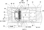
As shown in Figure 1, input switch module 20 comprises the first fixed block 21, removable 23, six axle power/torque sensors 24, contiguous block 28 and the second fixed block 22.The first fixed block 21 and the second fixed block 22 be fastening is positioned at the two ends of the input switch module 20 of bearing circle inside.Reverse ground for removable 23, be installed on the first fixed block 21 movably.Conjugant 26 can be sandwiched between the first fixed block 21 and removable 23.By at six axle power/torque sensors 24 between removable 23 and contiguous block 28, be connected to contiguous block 28 with removable 23.Contiguous block 28 is connected to the second fixed block 22.A plurality of input links 25 are connected in the outside face of removable 23 and the second fixed block 22, and being used for provides power or moment of torsion to six axle power/torque sensors 24.Each input link 25 comprises a pair of articulated element 25-1 and an elastic component 25-2.The first end 25-1-1 of this paired articulated element 25-1 is engaged in the groove 27 of the outside face that is formed on removable 23 pivotally, and the second end 25-1-2 of this paired articulated element 25-1 is engaged in the first end 25-2-1 of elastic component 25-2 pivotally, and the second end 25-2-2 of elastic component 25-2 is fixed in the outside face of the second fixed block 22 simultaneously.Shown in illustrative embodiments in, have four input links 25: (these directions refer to that bearing circle is with respect to driver's position for front input link 25a, rear input link 25b, left input link 25c and right input link 25d, for example, bearing circle is counted as the front in the face of driver's surface).
As shown in Figure 2, the present invention is topmost is characterised in that the input switch module 20 with six axle power/torque sensors 24 is installed in the assurance section 12 of bearing circle 10, simultaneously, be used for to the driver provide the feedback module 30 of switching manipulation sensation also be positioned at wherein (referring to, for example accompanying drawing 4).Therefore, to the input of input switch module 20 (for example depend on the driver, press forward, press backward, press left, press to the right, the twisting action of assurance section, etc.), generation is positioned at the switch output of the input switch module 20 of assurance section 12, thereby start feedback module 30 and provide feedback-induced (for example aud. snl. or vibration) to the driver, confirm that input switch module 20 is activated.
In other words, the output of the switch of the input switch module 20 in assurance section 12 for example can start by seven actions (seven motions), and the feedback that the driver can export as switch by for example experiencing vibration be confirmed switching manipulation.For example, seven actions can comprise: the power that pushing action produces when keeping assurance section (pressing when promoting the front surface of assurance section), the power (pressing when pulling the rear surface of assurance section) that is keeping pulling in assurance section power to produce, the of short duration power that presses generation by the whole assurance of firm grasping section; The power that produces by the twisting action to left handed twist assurance section; The power that produces by the twisting action of reversing assurance section to the right; The power that produces by the twisting action of reversing assurance section along left diagonal (anticlockwise direction) in folding (wrapping) assurance section; And the power that produces by the twisting action of reversing assurance section along right diagonal (clockwise direction) when folding assurance section.
The structure of the input switch module 20 in the assurance section 12 that is arranged on bearing circle is hereinafter described with reference to Fig. 2 and Fig. 3.
As shown in Figure 3, the first fixed block 21 of input switch module 20 is installed on first cross-sectional plane " line a " of assurance section 12, and simultaneously, the second fixed block 22 is installed on second cross-sectional plane " line b " of assurance section 12.In an illustrative embodiments, removable 23 inner surface that can reverse ground by the conjugant 26 with flexible material, be arranged on movably the first fixed block 21.
In other words, because the conjugant 26 with flexible material is bonded to the first fixed block 21 and the boundary section of removable 23, therefore can obtain the twisting of removable 23 on respect to the cw of the first fixed block 21 or anticlockwise direction.The inner surface of removable 23 is fixed in a side surface of six axle power/torque sensors 24 integratedly, hollow type contiguous block 28 is arranged on the inner surface of the second fixed block 22 integratedly, and the inner surface of contiguous block 28 is anchored on the opposite side surface of six axle power/torque sensors 24 integratedly.
Six axle power/torque sensors 24 use the routine six axle power/torque sensors with a plurality of elastic (not shown), the inner surface that it is connected in the inner surface of removable 23 and synchronously is connected in contiguous block 28.Each elastic of six axle power/torque sensors 24 has the mechanically deform characteristic, and for example, when any power or moment of torsion were applied thereto, elastic reversed because of elastic restoring force.
In another embodiment, feedback module 30 can be installed in the inboard of the assurance section 12 that separates with input switch module 20.For example, feedback module 30 can be arranged in assurance section 12, promptly to transmit the feedback-induced of switching manipulation to driver's hand dividually near the first fixed block 21 or the second fixed block 22.
In illustrative embodiments of the present invention as shown in Figure 4, the keystone configuration that is used for operating input switch module 20 of the present invention comprises a plurality of (for example four) input link 25, and these input links 25 are connected between the outside face of removable 23 and the second fixed block 22 with uniform distances.Input link 25 is given six axle power/torque sensors 24 for power or transmission of torque that will be consistent with driver's operating effort.Input link 25 comprises a pair of articulated element 25-1, it has first end 25-1-1 and the second end 25-1-2, first end 25-1-1 is bonded on the coupling end 29 of the external diameter surface that is formed on removable 23 pivotly by the link pin in the groove 27 of coupling end 29, the second end 25-1-2 is bonded on the first end 25-2-1 of elastic component 25-2 pivotly, and the second end 25-2-2 of elastic component is fixed in the external diameter surface of the second fixed block 22.
When the first end 25-2-1 of the elastic component 25-2 that is connected with the second end 25-1-2 pivotable of articulated element 25-1 is pressed, the first end 25-2-1 of elastic component 25-2 is along pressing direction about attachment point, the the second end 25-2-2 that for example is installed on the second fixed block 22 reverses, and gathers elastic restoring force at this.Simultaneously, the input side that six axle power/torque sensors 24 are connected in controller 40 is with to its output signal, and is connected in the outgoing side of controller 40 as the vibrating motor of feedback module 30.
Next the operation that is arranged on the switch module in bearing circle of the present invention that consists of as mentioned above will be described.
With reference to figure 4, if the driver presses by the front surface that promotes assurance section 12 when holding the assurance section 12 of bearing circle 10, the front surface (towards driver's surface) of assurance section 12 is pressed, and it provides pressure to the front input link 25a in four exemplary input links 25.
Therefore, the elastic component 25-2 of front input link 25-1 is pressed because of the elastic force that wherein gathers, and simultaneously articulated element 25-1 is promoted towards the first fixed block 21.Simultaneously, articulated element 25-1 be in along the groove 27 that is formed on the coupling end 29 of removable 23, towards the first fixed block 21 by the state of translation.At this moment, be connected in the six axle power/torque sensors 24 of removable 23, detect the power that is produced during by translation at articulated element 25-1, and to controller 40 output signals.
And controller 40 operation signal to be to start some function of this device, and such as AVN, HUD etc. sends operation signal to the vibrating motor as feedback module 30 simultaneously.Vibrating motor produces vibration subsequently and the driver can utilize this feedback to vibrate to experience the sensation of switching manipulation.
As shown in Figure 4, when the driver carries out push action by the rear surface that pulls assurance section 12 when holding the assurance section 12 of bearing circle 10, the rear surface of assurance section 12 is pressed, and it is exerted pressure to the rear input link 25b in four exemplary input links 25.Therefore, carry out and the identical operation of carrying out when front input link 25a is extruded, to start the other function of this device, for example AVN, HUD, etc.
Simultaneously, if the driver reverses assurance section 12 simultaneously to the left or to the right in the assurance section 12 of holding bearing circle 10, namely produce twisting by reversing to the left or to the right assurance section 12, pressure puts on respectively left input link 25c or the right input link 25d in four exemplary input links 25.Therefore, carry out operation identical when being pressed with front input link 25a, to start the other function of this device, for example AVN, HUD etc.
With reference to figure 5, in the assurance section 12 of driver at folding (wrap) bearing circle 10, by reversing assurance section 12 along left diagonal (cw) or right diagonal (conter clockwise) to produce twisting, a moment of torsion imposes on the articulated element 25-1 of each input link 25, a moment of torsion synchronously passes to removable 23 that is connected in articulated element 25-1, so that acquisition is in the left side of the conjugant 26 of relative flexibility material or the twisting of removable 23 on right.Be connected in the six axle power/torque sensors 24 of removable 23, detect the twisting of removable 23 and signal is exported to controller 40, the other specific function of its starter gear, such as AVN (audio frequency, video, navigation), head-up display (HUD), etc.
In addition, if the driver produces of short duration pressing by firmly holding whole assurance section 12 in the assurance section 12 of holding bearing circle 10, pressure is applied simultaneously to four input link 25a, 25b, 25c and 25d, and its other that starts this device needs the switching manipulation function.
The above describes the present invention in detail with reference to illustrative embodiments of the present invention.Yet, it will be understood by those skilled in the art that can also change these embodiments in the situation that do not depart from principle of the present invention and spirit, scope of the present invention is limited by appended claim and their equivalent form of value.
Claims (19)
1. switch module comprises:
The input switch module;
Feedback module, and
Controller, it is configured to receive the signal from described input switch module, and exports signal to device and described feedback module.
2. switch module as claimed in claim 1, wherein said input switch module comprises:
The first fixed block with first end and second end;
Have first end, the second end and circumferential part removable, the first end of wherein said removable reverses ground, is installed on movably described second end of described the first fixed block;
Contiguous block with first end and second end, the described first end of wherein said contiguous block are connected in described second end of described removable, and clamping has six axle power/torque sensors between described removable and described contiguous block;
The second fixed block with first end, the second end and circumferential part, the described first end of wherein said the second fixed block are installed on described second end of described contiguous block; And
A plurality of input links, the circumferential part of described removable is connected to the described circumferential part of described the second fixed block, wherein said input link, and is configured to apply power and/or moment of torsion to described six axle power/torque sensors equally spaced from opening around the circumferential surface of described removable and the second fixed block.
3. switch module as claimed in claim 2, the described first end of wherein said removable reverses ground, is installed on movably described second end of described the first fixed block by conjugant.
4. switch module as claimed in claim 3, wherein said conjugant is flexible material.
5. switch module as claimed in claim 2, each input link in wherein said a plurality of input links comprises:
Have a pair of articulated element of first end and the second end, wherein said first end is engaged in the circumferential surface of described removable pivotally; And
Elastic component with first end and second end, wherein said first end are pivotally connected to described the second end in described a pair of articulated element, and described the second end is installed on the circumferential surface of described the second fixed block regularly.
6. switch module as claimed in claim 5, the described first end of wherein said a pair of articulated element is engaged in the circumferential surface of described removable pivotally by the lug with groove.
7. switch module as claimed in claim 5, described second end of wherein said elastic component directly is installed on the described circumferential surface of described the second fixed block regularly.
8. switch module as claimed in claim 5, described second end of wherein said elastic component is installed on the described circumferential surface of described the second fixed block regularly by erecting frame.
9. switch module as claimed in claim 1, it is configured to be arranged in bearing circle.
10. switch module as claimed in claim 2, the described first end of wherein said the first fixed block is installed on the first inside face of bearing circle, and described second end of described the second fixed block is installed on the second inside face of described bearing circle.
11. switch module as claimed in claim 1, wherein said feedback module are positioned at described input switch module.
12. switch module as claimed in claim 1, wherein said feedback module are positioned at the position adjacent with described input switch module.
13. switch module as claimed in claim 2, wherein said feedback module is positioned at described contiguous block.
14. switch module as claimed in claim 1, wherein said feedback module involving vibrations motor, described vibrating motor are configured to produce vibration when receiving the output signal of self-controller.
15. switch module as claimed in claim 1, wherein said device are selected from audio system, video system, navigationsystem, heating system, cooling system, head-up display, turn signal lamp, head light, cruise control, interior light and seat position controller.
16. switch module as claimed in claim 1, wherein said device are head-up display.
17. switch module as claimed in claim 2, wherein said input switch module are configured to send the different signal relevant from driver's different motion action to described controller.
18. switch module as claimed in claim 17, wherein said motion action are selected from promotion, pull, press, twisting left, twisting to the right, along the jackknife action of left diagonal and along the jackknife action of right diagonal.
19. a switch module comprises:
The input switch module comprises:
The first fixed block with first end and second end;
Have first end, the second end and circumferential part removable, the described first end of wherein said removable is reversed ground, is installed on movably described second end of described the first fixed block;
Contiguous block with first end and second end, the described first end of wherein said contiguous block are connected in described second end of described removable, and clamping has six axle power/torque sensors between described removable and described contiguous block;
The second fixed block with first end, the second end and circumferential part, the described first end of wherein said the second fixed block are installed on described second end of described contiguous block; And
A plurality of input links, the circumferential part of described removable is connected to the described circumferential part of described the second fixed block, wherein said input link, and is configured to apply power and/or moment of torsion to described six axle power/torque sensors equally spaced from opening around the circumferential surface of described removable and the second fixed block;
Feedback module, and
Controller, it is configured to receive the signal from described input switch module, and exports signal to device and described feedback module.
Applications Claiming Priority (2)
| Application Number | Priority Date | Filing Date | Title |
|---|---|---|---|
| KR10-2011-0131713 | 2011-12-09 | ||
| KR1020110131713A KR101350177B1 (en) | 2011-12-09 | 2011-12-09 | Switch module mounted in the inner space of steering wheel |
Publications (2)
| Publication Number | Publication Date |
|---|---|
| CN103158631A true CN103158631A (en) | 2013-06-19 |
| CN103158631B CN103158631B (en) | 2017-03-01 |
Family
ID=48464854
Family Applications (1)
| Application Number | Title | Priority Date | Filing Date |
|---|---|---|---|
| CN201210223242.8A Active CN103158631B (en) | 2011-12-09 | 2012-05-21 | It is arranged on the switch module in steering wheel |
Country Status (5)
| Country | Link |
|---|---|
| US (1) | US9136075B2 (en) |
| JP (1) | JP6063147B2 (en) |
| KR (1) | KR101350177B1 (en) |
| CN (1) | CN103158631B (en) |
| DE (1) | DE102012207945B4 (en) |
Cited By (1)
| Publication number | Priority date | Publication date | Assignee | Title |
|---|---|---|---|---|
| CN107444463A (en) * | 2016-05-25 | 2017-12-08 | 高田株式会社 | Steering wheel |
Families Citing this family (8)
| Publication number | Priority date | Publication date | Assignee | Title |
|---|---|---|---|---|
| US20130277136A1 (en) * | 2011-01-03 | 2013-10-24 | Douglas Michael Young | Method for unobtrusive adaptation to enable power steering in vintage cars |
| US10067567B2 (en) | 2013-05-30 | 2018-09-04 | Joyson Safety Systems Acquistion LLC | Multi-dimensional trackpad |
| US10180723B2 (en) | 2013-10-08 | 2019-01-15 | Joyson Safety Systems Acquisition Llc | Force sensor with haptic feedback |
| KR101477589B1 (en) * | 2013-10-31 | 2014-12-31 | 김묘진 | Handle for generating control signal and vehicle having the same |
| US10466826B2 (en) | 2014-10-08 | 2019-11-05 | Joyson Safety Systems Acquisition Llc | Systems and methods for illuminating a track pad system |
| JP6930472B2 (en) * | 2018-03-28 | 2021-09-01 | 豊田合成株式会社 | Steering wheel |
| WO2021138077A1 (en) | 2019-12-30 | 2021-07-08 | Joyson Safety Systems Acquisition Llc | Systems and methods for intelligent waveform interruption |
| CN113460069B (en) * | 2021-06-29 | 2022-12-30 | 均胜均安汽车电子(上海)有限公司 | Steering wheel touch switch system and automobile with same |
Citations (6)
| Publication number | Priority date | Publication date | Assignee | Title |
|---|---|---|---|---|
| US6256558B1 (en) * | 1998-01-19 | 2001-07-03 | Denso Corporation | Vehicle display system with drive enforcement control |
| US20050280250A1 (en) * | 2004-06-17 | 2005-12-22 | Trw Automotive Safety Systems Gmbh | Vehicle steering wheel |
| KR100600164B1 (en) * | 2003-12-17 | 2006-07-12 | 기아자동차주식회사 | Turn indicator switch attached to the steering wheel and its operation method |
| JP2006298241A (en) * | 2005-04-22 | 2006-11-02 | Toyota Motor Corp | Vehicle display device |
| US20110172541A1 (en) * | 2009-12-18 | 2011-07-14 | Anthony Brian W | Handheld force-controlled ultrasound probe |
| US20110241850A1 (en) * | 2010-03-31 | 2011-10-06 | Tk Holdings Inc. | Steering wheel sensors |
Family Cites Families (14)
| Publication number | Priority date | Publication date | Assignee | Title |
|---|---|---|---|---|
| JP2000168468A (en) | 1998-12-04 | 2000-06-20 | Calsonic Corp | Information transmitting device for vehicle |
| US8364342B2 (en) | 2001-07-31 | 2013-01-29 | Immersion Corporation | Control wheel with haptic feedback |
| DE602005006674D1 (en) | 2004-07-29 | 2008-06-26 | Aphrodite Agencies Ltd | Steering control for automotive vehicles |
| JP4814594B2 (en) | 2005-09-14 | 2011-11-16 | 日立オートモティブシステムズ株式会社 | In-vehicle equipment operation device |
| JP2008041370A (en) | 2006-08-03 | 2008-02-21 | Toyota Motor Corp | Vehicle control device |
| JP4676408B2 (en) | 2006-09-29 | 2011-04-27 | 株式会社デンソーアイティーラボラトリ | Information input device |
| JP2008168840A (en) | 2007-01-15 | 2008-07-24 | Honda Motor Co Ltd | Vehicle steering device |
| JP4475288B2 (en) | 2007-04-20 | 2010-06-09 | 横浜ゴム株式会社 | Steering force detection device |
| DE102007024141B4 (en) | 2007-05-23 | 2014-11-13 | TAKATA Aktiengesellschaft | Sensor system for a component of a vehicle |
| JP2008301959A (en) | 2007-06-06 | 2008-12-18 | Tokai Rika Co Ltd | Steering wheel structure |
| ATE533567T1 (en) | 2008-05-21 | 2011-12-15 | Fiat Ricerche | HANDLE ELEMENT WITH HAPTIC FEEDBACK |
| JP2010228046A (en) * | 2009-03-27 | 2010-10-14 | Hitachi-Ge Nuclear Energy Ltd | Bending mechanism and control device and control method therefor |
| KR101386244B1 (en) | 2009-12-18 | 2014-04-17 | 한국전자통신연구원 | apparatus of movement input applied to steering apparatus and mobile control system using the same |
| WO2012094308A1 (en) * | 2011-01-03 | 2012-07-12 | Massachusetts Institute Of Technology | Quantitative elastography |
-
2011
- 2011-12-09 KR KR1020110131713A patent/KR101350177B1/en active Active
-
2012
- 2012-05-08 US US13/466,599 patent/US9136075B2/en active Active
- 2012-05-09 JP JP2012107873A patent/JP6063147B2/en active Active
- 2012-05-11 DE DE102012207945.9A patent/DE102012207945B4/en not_active Expired - Fee Related
- 2012-05-21 CN CN201210223242.8A patent/CN103158631B/en active Active
Patent Citations (6)
| Publication number | Priority date | Publication date | Assignee | Title |
|---|---|---|---|---|
| US6256558B1 (en) * | 1998-01-19 | 2001-07-03 | Denso Corporation | Vehicle display system with drive enforcement control |
| KR100600164B1 (en) * | 2003-12-17 | 2006-07-12 | 기아자동차주식회사 | Turn indicator switch attached to the steering wheel and its operation method |
| US20050280250A1 (en) * | 2004-06-17 | 2005-12-22 | Trw Automotive Safety Systems Gmbh | Vehicle steering wheel |
| JP2006298241A (en) * | 2005-04-22 | 2006-11-02 | Toyota Motor Corp | Vehicle display device |
| US20110172541A1 (en) * | 2009-12-18 | 2011-07-14 | Anthony Brian W | Handheld force-controlled ultrasound probe |
| US20110241850A1 (en) * | 2010-03-31 | 2011-10-06 | Tk Holdings Inc. | Steering wheel sensors |
Cited By (2)
| Publication number | Priority date | Publication date | Assignee | Title |
|---|---|---|---|---|
| CN107444463A (en) * | 2016-05-25 | 2017-12-08 | 高田株式会社 | Steering wheel |
| CN107444463B (en) * | 2016-05-25 | 2021-05-14 | 均胜安全系统日本株式会社 | steering wheel |
Also Published As
| Publication number | Publication date |
|---|---|
| DE102012207945A1 (en) | 2013-06-13 |
| JP6063147B2 (en) | 2017-01-18 |
| DE102012207945B4 (en) | 2021-09-30 |
| KR20130065032A (en) | 2013-06-19 |
| US9136075B2 (en) | 2015-09-15 |
| KR101350177B1 (en) | 2014-01-16 |
| CN103158631B (en) | 2017-03-01 |
| US20130147284A1 (en) | 2013-06-13 |
| JP2013121814A (en) | 2013-06-20 |
Similar Documents
| Publication | Publication Date | Title |
|---|---|---|
| CN103158631A (en) | Switch module built in steering wheel | |
| US9518620B2 (en) | Disconnector-type clutch for rear wheel-driving device in four-wheel driving electric vehicle | |
| WO2014145515A3 (en) | Hybrid axle assembly for a motor vehicle | |
| TW201200401A (en) | Bicycle electrical system | |
| JP2014058286A5 (en) | ||
| CN102963362A (en) | Motor vehicle, in particular automobile, and method for controlling a motor vehicle, in particular an automobile | |
| WO2012063399A1 (en) | Cable arrangement structure for vehicle | |
| JP2013510040A5 (en) | ||
| KR20160140743A (en) | Automobile steering system | |
| JP2016003002A (en) | Hybrid powertrain unit for motor vehicles with auxiliary device | |
| WO2007017719A3 (en) | Hybrid traction system | |
| JP2014168356A (en) | Case support member | |
| CN103085911A (en) | Handle switch | |
| WO2012087083A3 (en) | Turning control apparatus for a hybrid construction machine | |
| KR20130128170A (en) | Driving device for rear wheels of 4 wheel driving electric vehicle | |
| WO2009050402A3 (en) | Method and system for controlling a power unit with power bypass | |
| JP3031272U (en) | Electrical connection device for components that are spatially separated from each other | |
| CN201951246U (en) | Electric control transfer case device of automobile | |
| KR101467106B1 (en) | Testing apparatus for tracked vehicle steering system | |
| TW202504816A (en) | First electric device, second electric device, and control system of human-powered vehicle | |
| KR20130033834A (en) | Direction guiding device for vehicle | |
| TWI751405B (en) | Device and control system for wireless communication | |
| KR100783512B1 (en) | Vibration Reduction Device for Vehicle Steering Wheel | |
| JP2004175327A (en) | Twin bicycle with interlocking type rear wheel brake | |
| JP2011255763A (en) | Parallel hybrid vehicle |
Legal Events
| Date | Code | Title | Description |
|---|---|---|---|
| C06 | Publication | ||
| PB01 | Publication | ||
| C10 | Entry into substantive examination | ||
| SE01 | Entry into force of request for substantive examination | ||
| GR01 | Patent grant | ||
| GR01 | Patent grant |