CN1031376C - Electronic game device capable of producing pseudo-stereo sound - Google Patents
Electronic game device capable of producing pseudo-stereo sound Download PDFInfo
- Publication number
- CN1031376C CN1031376C CN 90100211 CN90100211A CN1031376C CN 1031376 C CN1031376 C CN 1031376C CN 90100211 CN90100211 CN 90100211 CN 90100211 A CN90100211 A CN 90100211A CN 1031376 C CN1031376 C CN 1031376C
- Authority
- CN
- China
- Prior art keywords
- sound
- output
- signal
- data
- audio
- Prior art date
- Legal status (The legal status is an assumption and is not a legal conclusion. Google has not performed a legal analysis and makes no representation as to the accuracy of the status listed.)
- Expired - Fee Related
Links
Images


Landscapes
- Electrophonic Musical Instruments (AREA)
Abstract
Description
本发明涉及电子游戏装置,更准确地说,涉及具有二维图形显示的微处理器控制的电子游戏装置。更具体地说,本发明涉及在这种电子游戏装置中伪立体声音乐和声响效果的产生。再具体地说,本发明涉及在使用外部存储器卡盒的游戏装置(例如,电子电视游戏装置或便携式手持电子液晶显示型的游戏装置)中用于产生音乐、声响效果和其它声音的伪立体声产生装置和方法。This invention relates to electronic gaming devices, and more particularly to microprocessor controlled electronic gaming devices having two-dimensional graphical displays. More particularly, the present invention relates to the generation of pseudo-stereo music and sound effects in such electronic game devices. More particularly, the present invention relates to pseudo-stereo sound generation for producing music, sound effects, and other sounds in gaming devices using external memory cartridges, such as electronic television gaming devices or portable handheld electronic liquid crystal display type gaming devices. Apparatus and methods.
常规电子电视和其它游戏装置根据存储装置中存储的表示声音的数字数据而产生诸如音乐、声响,等等。然而,在过去,这样产生的声音信号由于种种原因,都是单声道的而不是立体声的。Conventional electronic televisions and other gaming devices produce, for example, music, sounds, etc. based on digital data representing sounds stored in a memory device. However, in the past, the sound signal thus produced was mono rather than stereo for various reasons.
众所周知,“立体”声通常有两个独立的(但相关的)声频通道(例如“左”声道和“右”声道)。每个声频通道包括独立的声频(及其它)信号处理电路。由独立的立体声声频通道所产生的信号通常由空间上分开的若干声频换能器所重放(例如,“左”和“右”扬声器或耳机换能器)。As we all know, "stereo" sound usually has two separate (but related) audio channels (eg "left" and "right" channels). Each audio channel includes independent audio (and other) signal processing circuitry. The signals produced by separate stereo audio channels are typically reproduced by several spatially separated audio transducers (eg "left" and "right" speaker or headphone transducers).
在录音行业,通常将不同的立体声通道独立地进行录制和/或混合,使得在重放时这两个通道中所存在的声频信号是有差别然而相关的。由于在不同通道中同时(或几乎同时)产生的相关声音间的相位和其它信号的关系,听众感觉出音质是二维空间的。由于听众感觉到他沉浸于从多个空间上分开的声源幅射出的声音包络线之中,这种立体声产生较为令人愉快的收听感受。这种效果在通过立体声耳机来收听立体声时尤为增强。In the recording industry, it is common for different stereo channels to be recorded and/or mixed independently so that upon playback the audio signals present in the two channels are distinct but related. Audiences perceive sound quality as two-dimensional due to phase and other signal relationships between related sounds produced simultaneously (or nearly simultaneously) in different channels. Stereo produces a more pleasing listening experience, since the listener feels immersed in the envelope of sound radiating from multiple spatially separated sources. This effect is especially enhanced when listening to stereo sound through stereo headphones.
众所周知,利用常规计算机技术,通过产生分别由存储在数字存储器中的左声道和右声道数据所控制的左、右通道的声源来合成立体声是可能的。但是,和只产生单声效果的场合相比,产生这种立体声所需的存储器通常要增加一倍。而且,还必须提供用于左声道和右声道的分开的声音合成电路(“声源”),从而增加了合成电路结构的复杂性和成本。As is well known, using conventional computer technology, it is possible to synthesize stereophonic sound by generating sound sources for left and right channels respectively controlled by left and right channel data stored in digital memory. However, the memory required to produce this stereophonic sound is usually doubled compared to the occasion where only the monophonic effect is produced. Furthermore, separate sound synthesis circuits ("sound sources") must be provided for the left and right channels, thereby increasing the complexity and cost of the synthesis circuit structure.
在日本实用新型公开公报66800/1983号中公开了伪立体声发生装置。该参考文件公开了用AM广播接收机(调谐器)来接收AM广播信号并增强所接收到的AM信号(单声道的),以产生伪立体声的效果。该文献并未谈及在存储器资源有限的游戏装置中形成立体声的问题。A pseudo-stereo generator is disclosed in Japanese Utility Model Publication No. 66800/1983. This reference discloses the use of an AM broadcast receiver (tuner) to receive an AM broadcast signal and enhance the received AM signal (mono) to produce a pseudo-stereo effect. This document does not address the problem of creating stereo sound in gaming devices with limited memory resources.
本发明提供了用便宜而比较简单的实际上减少存储器要求的电路来产生伪立体声的立体声产生装置及方法。The present invention provides a stereophonic generating apparatus and method for producing pseudo-stereophonic sound with inexpensive and relatively simple circuitry that substantially reduces memory requirements.
本发明还提供了可用于带有伪立体声产生电路的电视游戏装置中的新颖的存储器卡盒。The present invention also provides a novel memory cartridge usable in a video game device with a pseudo-stereo sound generating circuit.
本发明进一步提供了包括伪立体声发生器的新颖手持式电视游戏装置。The present invention further provides a novel handheld video game device including a pseudo-stereo generator.
本发明提供的另一重要的优越特性是,在手持式游戏装置中可通过立体声耳机产生立体声的声响效果。Another important superior feature provided by the present invention is that stereo sound effect can be produced through stereo earphones in the handheld game device.
根据本发明的一个方法,提供多个独立的声音合成电路。有些声音合成电路可用于产生左声道输出信号,而另一些声音合成电路可用产生右声道输出信号,还有一些声音合成电路用于产生加到左右两声频输出通道的声频信号。然而,在本发明的最佳实施例中,没有将声音合成电路永久地指派为声频输出通道。而是在声音合成电路的输出端设置声频开关电路,用来有选择地将各种合成电路的输出信号送向所要求的左或右声频输出通道。可在程序控制下改变模拟开关电路的状态,从而改变由特定声音合成电路所产生的信号所指向的声频输出通道。According to one method of the present invention, a plurality of independent sound synthesis circuits are provided. Some sound synthesizing circuits can be used to generate a left channel output signal, while other sound synthesizing circuits can be used to generate a right channel output signal, and still other sound synthesizing circuits can be used to generate audio signals that are applied to both left and right audio output channels. However, in the preferred embodiment of the present invention, the sound synthesis circuit is not permanently assigned as an audio output channel. Instead, an audio switching circuit is provided at the output end of the sound synthesis circuit to selectively send the output signals of various synthesis circuits to the required left or right audio output channel. The state of the analog switch circuit can be changed under program control, thereby changing the audio output channel to which the signal generated by the specific sound synthesis circuit is directed.
例如,按照本发明的特征,配备有左声道声频信号总线和右声道声频信号总线。左声道声频信号总线将左声道声频信号提供给左声道声频信号放大器及相关联的声音换能器(例如,立体声耳机的左声道换能器)。同样地,右声道声频信号将右声道声频信号加至右声道声频放大器及相关联的声音换能器(例如,同一立体声耳机的右声道换能器)。还配备了多个声音合成电路(声源)。最佳实施例中的声源在程序控制下独立地产生各种声频信号(例如,音高,声响效果,等等)。多个声源的每一(任一)输出信号可通过左声道模拟开关耦合到左声道声频信号总线和/或通过右声道模拟开关耦合到右声道声频信号总线。该模拟开关的状态由程序指令控制,从而可按所要求那样动态地加以改变。For example, according to a feature of the present invention, a left channel audio signal bus and a right channel audio signal bus are provided. The left channel audio signal bus provides the left channel audio signal to a left channel audio signal amplifier and an associated sound transducer (eg, the left channel transducer of a stereo headset). Likewise, the right channel audio signal applies the right channel audio signal to a right channel audio amplifier and associated sound transducer (eg, the right channel transducer of the same stereo headphone). Also equipped with multiple sound synthesis circuits (sound sources). The sound sources in the preferred embodiment independently generate various audio signals (eg, pitch, sound effects, etc.) under program control. Each (any) output signal of the plurality of sound sources may be coupled to a left channel audio signal bus via a left channel analog switch and/or coupled to a right channel audio signal bus via a right channel analog switch. The state of the analog switch is controlled by program instructions so that it can be changed dynamically as required.
这样,可通过简单地选择与特定声源的输出端相连的模拟开关的状态,来将该特定声源的输出信号仅加到左声道声频信号总线、仅加到右声道声频信号总线,或者加到左、右声频信号的两条总线(而这些状态是可以在程序控制下按要求改变的)。通过同时地或有选择地打开或关闭和特定声源相关联的左声道或右声道模拟开关,可将声音信号送向一个、另一个或两个声频输出声道。In this way, the output signal of a specific sound source can be added only to the left channel audio signal bus and only to the right channel audio signal bus by simply selecting the state of the analog switch connected to the output terminal of the specific sound source, Or add to the two buses of the left and right audio signals (and these states can be changed as required under program control). Audio signals may be routed to one, the other, or both audio output channels by simultaneously or selectively opening or closing left or right channel analog switches associated with particular sound sources.
由于按照本发明有可能对特定声源的输出信号选择其所加的声道,所以无需存储对应于两个立体声音乐节目的声音发生数据的完全不同的集合(左声道和右声道)。也就是说,只需存储用于在特定时间内控制待激活的多个发声源的不同的声音发生数据。用于选择将各种声源的输出信号加到声频通道的附加数据只需要很少的附加存储空间,只要加少许的附加存储量便可提供伪立体声。由于对特定声源信号准备加到哪一通道有可能选择,所以存储器需求基上没有增加(这与将左、右声道信号分开存储在存储器中的情况大不相同,该情况通常需要存储单声道的声频信息所需存储量的两倍)。此外,本发明提供更多用途而且不太复杂的电路结构,使其尤其适于在小型化的便携式电视游戏装置中产生声响效果。Since it is possible according to the invention to select the channel to which the output signal of a particular sound source is added, there is no need to store completely different sets of sound generation data (left and right channels) corresponding to two stereophonic music programs. That is, it is only necessary to store different sound generation data for controlling a plurality of sound generation sources to be activated within a certain time. The additional data used to selectively add the output signals of various sound sources to the audio channel requires only a small amount of additional storage space, and pseudo stereophonic sound can be provided with only a small amount of additional storage. Since it is possible to select which channel a particular sound source signal is to be applied to, there is essentially no increase in memory requirements (this is very different from storing the left and right channel signals separately in memory, which usually requires a single twice the amount of storage required for the audio information of the channel). Furthermore, the present invention provides a more versatile and less complex circuit configuration, making it particularly suitable for producing sound effects in miniaturized portable video game devices.
在以上所述电视游戏装置中,由声源信号发生装置所产生的声源信号于是通过由模拟开关装置执行的切换动作而有选择地输出到第一和第二(例如,左和右)声音信号通道,以产生伪立体声。In the above-mentioned video game device, the sound source signal generated by the sound source signal generating means is then selectively output to the first and second (for example, left and right) sound sources through the switching action performed by the analog switch means. signal channel to produce pseudo-stereo sound.
本发明还提供与电视游戏装置可拆卸接合的存储器卡盒,用于产生立体声控制信号。电视游戏装置包括声源信号发生装置,用来按照由存储器卡盒所提供数据产生声音信号。开关装置可将声音信号发生装置的输出连接到第一和第二声音输出通道中的一个或两者,并有选择地将声源信号发生装置的输出加到第一和/或第二声音信号输出通道。对产生音乐来讲,该存储器卡盒最好存储代表音符或休止符的持续时间(时间长度)的数据、与音高相关联的数据,以及说明按规定的音高和音长所产生的声音送向哪一个声频输出通道的“方向”数据。The present invention also provides a memory cartridge removably engageable with a video game apparatus for generating stereo control signals. The video game apparatus includes sound source signal generating means for generating sound signals in accordance with data supplied from the memory cartridge. The switch means can connect the output of the sound signal generating means to one or both of the first and second sound output channels and selectively add the output of the sound source signal generating means to the first and/or second sound signal output channel. For music production, the memory cartridge preferably stores data representing the duration (length of time) of a note or rest, data associated with a pitch, and a description of the direction in which the sound produced at the specified pitch and duration is directed. Which audio output channel's "direction" data.
存储器卡盒存储和音乐或声响信号(即音符和休止符)的顺序相对应的数据集合序列,并且,在最佳实施例中以所述序列的次序(对序列中不同数据集的存取在时间分开的情况下)存取数据集,以便描述音乐或声响信号的序列。在最佳实施例中,存储器卡盒可存储与音乐声响信号序列中给定时刻相应的多个数据集合,这样可对多个声源提供同步控制。The memory cartridge stores a sequence of data sets corresponding to the sequence of the musical or acoustic signal (i.e., notes and rests), and, in the preferred embodiment, in the order of the sequence (access to the different data sets in the sequence in time separate case) to access data sets for describing sequences of music or sound signals. In a preferred embodiment, the memory cartridge stores multiple data sets corresponding to a given moment in the musical sound signal sequence, thus providing simultaneous control of multiple sound sources.
最佳实施例中的存储器卡盒还存储用于分别读出表示预定计时的声音数据的程序控制指令,从而提供将音长(持续时间)相关数据、音高相关数据和左/右通道区分符(“方向”)数据按照从所述存储器卡盒所读出的程序控制指令送至电视游戏装置中去的机制。The memory cartridge in the preferred embodiment also stores program control instructions for separately reading out sound data representing predetermined timings, thereby providing length (duration) related data, pitch related data, and left/right channel specifiers ("Direction") The mechanism by which data is sent to the video game device according to program control instructions read from the memory cartridge.
本发明的最佳实施例中的存储器卡盒最好存储表示待产生声音不同方面的多种数据结构。尤其是,该卡盒最好存储用于表示通常由活页乐谱所表示信息的乐谱数据表(例如,音符和休止符序列中的音符的音高和音长,以及休止时间)。这种乐谱数据表最好依次提供到持续时间数据结构的偏移地址,将乐谱表中存储的不同音符及休止符的持续时间映象为适合的声音发生电路的计时控制信号,以及提供到频率数据结构的偏移地址,将不同音高映象为适合的声音发生电路的音高控制信号。The memory cartridge in the preferred embodiment of the present invention preferably stores multiple data structures representing different aspects of the sound to be produced. In particular, the cartridge preferably stores a score data table for representing information typically represented by sheet music (eg, pitch and duration of notes in a sequence of notes and rests, and rest times). Such a score data table preferably in turn provides offset addresses to the duration data structure, maps the durations of the different notes and rests stored in the score table to timing control signals for appropriate sound generation circuits, and provides frequency data The offset address of the structure maps the different pitches to the appropriate pitch control signal for the sound generation circuit.
随着该存储器卡盒中所存储计算机程序的进行,按预定时序从乐谱表中读出音长相关数据、音高相关数据和说明左/右通道方向的数据(这些时序是由程序流另外确定的)。所产生的声音的音高是按音高相关数据确定的,而该音高的维持的时间周期(即,音长或持续时间)是按照音长(持续时间)相关数据确定的。如上所述的输出多路转换操作是按照说明左/右通道方向的数据执行的,以获得所要求的右通道声音输出或左通道声音输出。这样,便可以按伪立体声形式产生存储在乐谱表中的音符序列。由于将左或右通道数据存储在存储器卡盒里,以及左/右通道选择数据说明了由任一特定音高和音长数据所表示的声频准备指向哪一通道,所以,有可能非常容易地产生或形成诸如音乐或声响的伪立体声。Along with the carrying out of the stored computer program in this memory card box, read out sound length relevant data, pitch relevant data and the data of explanation left/right channel direction (these timings are determined by program flow in addition) of). The pitch of the generated sound is determined according to the pitch-related data, and the time period (ie, sound length or duration) for which the pitch is maintained is determined according to the sound length (duration) related data. The output multiplexing operation as described above is performed according to the data specifying the left/right channel direction to obtain the desired right-channel sound output or left-channel sound output. In this way, the sequence of notes stored in the score sheet can be produced in pseudo-stereo form. It is possible to generate Or form a pseudo-stereo like music or sound.
按照本发明的另一特征,将立体声/单声道变换电路连接到从中独立地输出左和右通道声音信号的立体声源。立体声/单声道变换电路最好包括可接纳通用型立体声音频插头的耳机插座。耳机插座至少包括一个开关触点以及左和右通道声频触点。左通道声频触点将左通道声频信号导向耳机左通道声频换能器,而右通道声频触点类似地将右通道声频信号导向耳机右通道声频换能器。此外,还配置了单声道声频换能器(例如,电视游戏装置内的扬声器)。According to another feature of the present invention, the stereo/mono conversion circuit is connected to a stereo source from which left and right channel sound signals are independently output. The stereo/mono conversion circuit preferably includes a headphone jack which accepts a universal stereo audio plug. The headphone jack includes at least one switch contact and left and right channel audio contacts. The left channel audio contact directs the left channel audio signal to the earphone left channel audio transducer, while the right channel audio contact similarly directs the right channel audio signal to the earphone right channel audio transducer. In addition, a mono audio transducer (eg, a speaker in a video game console) is also provided.
当没有耳机插头插入该耳机插座时,该开关触点产生自动地给与耳机插座左、右通道输出端相连的独立的左、右通道声频信号通路去激励并自动地激活将左、右通道声频信号一起组合成单声道信号的组合(“混合”)电路的控制信号。该组合电路将组合后的单声道信号加到电视游戏装置的内部扬声器。另一方面,耳机插座中耳机插头的插入,改变了由耳机插座开并触点所产生的控制信号的状态,即,给组合电路去激励(并由此自动地给内部扬声器去激励)而取代以完全独立的到耳机插座左、右通道触点的左、右声道的信号通道。When no earphone plug is inserted into the earphone jack, the switch contacts automatically de-energize the independent left and right channel audio signal paths connected to the left and right channel output terminals of the earphone jack and automatically activate the left and right channel audio signals. The signals are combined together into a control signal for a combining ("mixing") circuit of the mono signal. The combining circuit applies the combined mono signal to the internal speaker of the video game unit. On the other hand, the insertion of an earphone plug in an earphone jack changes the state of the control signal generated by the opening and closing contacts of the earphone jack, i.e. deenergizes the combined circuit (and thus automatically deenergizes the internal speaker) instead of With completely independent signal paths for left and right channels to the left and right channel contacts of the headphone socket.
这样,当没有将耳机插头插入耳机插座时,将所合成的单声道声音信号供给内部扬声器。另一方面,当耳机插头插入耳机插座时,没有禁止左通道和右通道的信号通路,而是将它们分别输出到耳机插座的左通道和右通道的触点,而这样将立体声输出到插入耳机插座的立体声耳机。这样,用户可容易地将电视游戏装置作为完全独立的部件来玩并可收听到由内部扬声器产生的单声道声音。另一方面,如果游戏机使用者想要感受由上述伪立体声发生能力所提供的声音增强效果,那么他只需将立体声耳机的插头插入耳机插座,并将耳机戴在其头上。In this way, when the earphone plug is not inserted into the earphone jack, the synthesized monaural sound signal is supplied to the internal speaker. On the other hand, when the headphone plug is inserted into the headphone socket, instead of disabling the signal paths of the left and right channels, they are respectively output to the contacts of the left and right channels of the headphone socket, and thus stereo output to the plugged-in headphones Socket for stereo headphones. In this way, the user can easily play the video game device as a completely separate unit and listen to the mono sound produced by the internal speaker. On the other hand, if the gaming machine user wants to experience the sound enhancement effect provided by the above-mentioned pseudo-stereo sound generation capability, he only needs to plug the plug of the stereo earphone into the earphone jack and put the earphone on his head.
这样,即使数据卡盒中存储的声音发生数据控制声音发生电路产生伪立体声,本发明的这一特征也提供了能够在立体声和单声道之间选择的新颖的立体声/单声道变换电路。这种立体声/单声道选择电路对于在手持式电视游戏机中产生声响是非常有效的。Thus, even though the sound generating data stored in the data cartridge controls the sound generating circuit to generate pseudo stereo, this feature of the present invention provides a novel stereo/mono conversion circuit capable of selecting between stereo and mono. This stereo/mono selection circuit is very effective for producing sound in a handheld video game machine.
联系附图,从以下对本发明的目前最佳实施例的详细描述,本发明的这些和其它一些目的、特征、方面和优点会变得更明显和容易理解,附图中:These and other objects, features, aspects and advantages of the present invention will become more apparent and understandable from the following detailed description of the presently preferred embodiment of the present invention in conjunction with the accompanying drawings, in which:
图1为可便利地利用本发明的示范性的手持式液晶显示型的电视游戏装置的侧向透视图;1 is a side perspective view of an exemplary handheld liquid crystal display type video game device that may advantageously utilize the present invention;
图2为图1游戏装置中所包含的电子线路的原理框图;Fig. 2 is a functional block diagram of the electronic circuit included in the game device of Fig. 1;
图2A为图2所示微计算机体系结构的更详细的原理图;Figure 2A is a more detailed schematic diagram of the microcomputer architecture shown in Figure 2;
图3A—3D为图2所示CPU地址空间的示范性映象的原理图;3A-3D are schematic diagrams of exemplary maps of the CPU address space shown in FIG. 2;
图4为图2所示的示范性声音发生器的原理框图;Figure 4 is a functional block diagram of the exemplary sound generator shown in Figure 2;
图4A为图4中所示寄存器NR50、NR51和NR52中的示范性内容;Fig. 4A is the exemplary content in register NR50, NR51 and NR52 shown in Fig. 4;
图5为图4中所示声音发生电路的一个示范性实例的更详细的电路图;Figure 5 is a more detailed circuit diagram of an illustrative example of the sound generating circuit shown in Figure 4;
图5A—5D为图4中所示声音发生电路中声音控制寄存器的示范性内容的原理图;5A-5D are schematic diagrams of exemplary contents of the sound control register in the sound generating circuit shown in FIG. 4;
图6为示范的乐谱的图形说明,还示出一些用于控制图4所示的不同声音发生电路的控制参数;Figure 6 is a graphical illustration of an exemplary musical notation, also showing some control parameters for controlling the various sound generating circuits shown in Figure 4;
图7A—7B共同为由最佳实施例中图2的微计算机所执行的示范程序控制步的原理性流程图,这些控制步用于产生由图6乐谱所表示的音乐;Figures 7A-7B are collectively a schematic flow diagram of exemplary program control steps executed by the microcomputer of Figure 2 in a preferred embodiment for producing the music represented by the musical score of Figure 6;
图8为图4所示结构的示范性立体声/单声道选择电路的电路原理图;以及Fig. 8 is the schematic circuit diagram of the exemplary stereo/mono selection circuit of structure shown in Fig. 4; And
图9A—9D为图1和图2中所示存储器卡盒示范内容的原理图。9A-9D are schematic diagrams of exemplary contents of the memory cartridge shown in FIGS. 1 and 2 .
首先描述由本发明目前最佳的示范性实施例所提供的完整的电子游戏装置。接着给出该最佳实施例中微计算机结构的更详细描述,包括微计算机的示范性结构和微计算机的示范的存储器组织。然后,给出最佳实施例的声音发生器的详细描述。关于声音发生器,首先描述最佳实施例声音发生器的总的结构和操作,包括以彼此配合的方式更好地使用多个独立声音发生电路,以产生伪立体声。其次,给出多个独立声音发生电路的一个示范性结构及操作的详细描述。接着给出可执行的示范程序控制步和可由最佳实施例的微计算机存取用以产生一行音乐的相关的示范数据结构的描述。最后,给出示范的立体声/单声道声音变换电路的描述。The complete electronic game device provided by the presently preferred exemplary embodiment of the present invention will first be described. A more detailed description of the architecture of the microcomputer in the preferred embodiment is given next, including an exemplary architecture of the microcomputer and an exemplary memory organization of the microcomputer. Then, a detailed description of the sound generator of the preferred embodiment is given. With respect to the sound generator, the general structure and operation of the preferred embodiment sound generator will first be described, including the better use of multiple independent sound generating circuits in cooperation with each other to produce pseudo-stereo sound. Next, a detailed description of an exemplary structure and operation of multiple independent sound generating circuits is given. A description follows of exemplary program control steps executable and associated exemplary data structures accessible by the microcomputer of the preferred embodiment to generate a line of music. Finally, a description is given of an exemplary stereo/mono sound conversion circuit.
图1为展示按照本发明目前最佳的示范性实施例,即示范性手持式液晶电子游戏机外壳的立视图。该手持式液晶游戏机(下文称为“游戏机”)10包括配置有液晶显示(LDC)屏14的匣12,所述液晶显示屏包括在其前部或上部表面按照点阵方式排列的点显示段。FIG. 1 is an elevational view showing a casing of an exemplary handheld liquid crystal electronic game machine according to the presently preferred exemplary embodiment of the present invention. The handheld liquid crystal game machine (hereinafter "game machine") 10 includes a
在匣12的背部或下部表面上与LCD屏14相对的部位形成插入口68。可将一个外部ROM卡盒16插入式地插到该插入口68。更具体地说,在插入口68内配置有32针接插件20。通过将外部ROM卡盒16插进插入口68,外部ROM卡盒16印刷电路板边缘形成的接插件(未示出)以电连接和机械连接的形式与该接插件20相连接。这样,外部ROM卡盒16可联接/可拆卸地与游戏机10相联接。An insertion port 68 is formed on the back or lower surface of the
如前文所述,外部ROM卡盒16为“存储器卡盒”,而将该存储器卡盒插入其中的游戏装置10为“主装置”。卡盒16和主装置10组合构成电子游戏装置。可将不同的存储器卡盒16插进插入口68以提供不同的程序控制指令,从而改变所玩的游戏。As described above, the
在外部ROM卡盒16中包括了外部ROM16a(见图9 A)。在外部ROM16a的程序控制指令区310内存储游戏程序。此外,众所周知,卡盒也可包括附加的存储器装置(例如,扩展RAM,存储体控制器(MBC),等等)。当将外部ROM卡盒16插入游戏机10,便执行游戏程序,使得在LCD屏14上显示出图象,由扬声器11或通过与插座64连接的耳机产生游戏音乐。An
在盒12中还配置6针接插件65,利用该接插件可通过适当电缆将该游戏机与其它机器连接,使得当外部卡盒包括多选手游戏程序时,就可进行多选手间的竞赛。Also dispose 6 pin connectors 65 in
在最佳实施例中将包含十字键开关18的用户输入装置配置在盒12正面或上面LCD屏14下方的左侧部位,如图1所示。十字键开关18带有四个方向指定部或触点,按下其中任一个,例如,便可能使在显示器14上所显示的字符向上、或向下、或向左、或向右移动。此外,如图1所示,在匣12正面或上面的LCD屏14下方的右侧部位配置有两个按钮开关70a和70b。当需要控制在LCD屏14所显示的游戏字符执行各种预定功能时,可操纵这两个按钮70a和70b。例如,当按钮开关70a按下时,所显示的字符可能跳跃,或当按下按钮开关70b时,该字符可看来象是掷石块、或掷球、或投掷各种其它物体。这样来装置十字键开关18使之可用左手的姆指来操作,右手与右手协同把匣12夹在手中,并将按钮开关70a和70b装置成可由右手的姆指来操作。In the preferred embodiment, the user input device including the cross
而且,在游戏机10的匣12的正面或上面装有启动开关72和选择开关74。如从图1可见的启动开关72和选择开关74安装在十字键开关18和按钮开关70a和70b下方的区域78中。将这些开关72和74集中安装以便可用左手和右手中任一只手的姆指来加以操作(在左手和右手握着游戏机10的匣12的同时)。换言之,可对开关72和74加以操作而无需明显改变手的位置。例如,通过使用选单屏使用选择开关74来选择正在显示游戏的操作方式。关于这点。可用选择开关74来选择若干个玩游戏级别中的一个。此外,可将选择游戏字符可用的“武器”的功能指定给择开关74。Also, an activation switch 72 and a selection switch 74 are mounted on the front or top of the
操作启动开关72来启动所选游戏。所以,通常在游戏期间不必操作启动开关72和选择开关74。然而,由于将暂停(PAUSE)功能也指定给启动开关72,所以当要求游戏暂时停止时可按下启动开关72。要在这种暂停之后启动游戏,可再次按下启动开关72。而且,有可能在程序控制下使启动开关72和选择开关74拥有许多其它的功能,从而使在玩游戏过程中动态地改变指定给这些开关的功能。The start switch 72 is operated to start the selected game. Therefore, it is generally not necessary to operate the activation switch 72 and the selection switch 74 during the game. However, since a pause (PAUSE) function is also assigned to the start switch 72, the start switch 72 can be pressed when a temporary stop of the game is required. To start the game after such a pause, the start switch 72 can be pressed again. Furthermore, it is possible to program enable switch 72 and select switch 74 to have many other functions, so that the functions assigned to these switches can be dynamically changed during game play.
此外在匣12上还装有通/断开关1,电池电位灯13、对比度调节50和音量调节66。In addition, an on/off
游戏装置10的核心是图2所示的微计算机22(游戏装置中电子电路的详细原理图)。微计算机10包括CPU24,仅仅作为例子它可用商业上现有的微处理器诸如Z80型的VLSI集成电路微处理器芯片来实现。CPU24通过时序部件25a、控制总线26a、地址缓冲器25b和地址总线26b、数据缓冲器25c和数据总线26c(这些总线和相关器件也将CPU与工作RAM或暂时存储器23连接)和32针卡盒接插件20相连接(从而使之与卡盒16内的存储器和其它元件相连接)。当外部ROM卡盒16与游戏机10啮合时,CPU24与外部ROM卡盒16相结合并协同工作。The core of the
现在更具体地参考图2A,CPU24与最佳实施例中的地址译码器33和存储器选择(体切换)电路32相配合以便在CPU的地址空间内选通各种装置(例如,卡盒16中的内部ROM30、内部RAM28、和外部ROM16a)。此外,地址译码器33可用来让CPU24选通图2所示其它方框中所含各种外部控制寄存器(例如,声音发生器58中的控制寄存器)或可由其它类似的地址译码器执行该功能。Referring now more specifically to FIG. 2A,
如图2A所示,CPU24最好包含内部8位的通用和专用寄存器,16位的程序计数据器PC和16位的堆栈指针SP。寄存器A可用作累加器而另一寄存器F可用作标志寄存器。CPU24最好具有允许包含以下内容的相关指令集合:在寄存器或寄存器对之间进行的各种8位和16位传送指令;各种8位和/或16位的算术运算指令(例如,ADD、SUB、AND/OR、INC、DEC、等等),各种移位/环移操作指令(例如将所规定的寄存器内容向左/右环移),各种位控制操作指令(例如,在所说明的寄存器中置位所说明的位)、条件和无条件转移指令,子程序调用和返回操作以及各种程序控制操作(例如,启动、停止、空操作等等)以上这些均为本专业技术人员所熟知。As shown in FIG. 2A,
最佳实施例中CPU24在存储于存储器卡盒16中的程序控制指令的控制下执行这样一些操作,从而响应用户通过用户输入装置18所形成的用户输入信号而在显示器14上提供玩游戏的显示。此外,CPU控制声音发生器58在存储于卡盒16中所述相同的程序控制指令的控制下产生与所玩游戏相应的音乐和/或声响。In the preferred embodiment,
再次参考图2,通过响应石英晶体元件24a的振荡电路24b而提供时钟脉冲给CPU24。时钟脉冲除法器24c产生一种或多冲时钟脉冲速率,并可由CPU24对该除法器24c进行编程,将由振荡电路24b产生的时钟脉冲按要求的比率相除。Referring again to FIG. 2, clock pulses are supplied to the
也可装备可编程的外部硬件计时电路24d,使CPU能判定当前所需时间间隔已过的时刻。在最佳实施例中,CPU24可装入带有表示时间区间长度的数值的计时电路24d并且启动该计时器。该计时电路24d可自动地测定时间间隔并且当该时间间隔过去时,该计时电路可产生中断信号,并将该中断信号加至CPU24(例如,通过中断控制器24i)来对CPU报警时间间隔已过去。这样,CPU便有计时能力而无需使用软件计时循环(它可能占用CPU处理时间及资源)。如果愿意,该计时电路24d也可用于由声音发生器58所产生音符的计时(将作简短说明)。A programmable external
在最佳实施例中,在DMA控制器34的控制下,CPU24将显示数据通过行缓冲器36输出到LCD控制器38。LCD控制器38通过LCD显示RAM接口40和控制地址和数据总线连接到显示RAM42。In the preferred embodiment,
LCD控制器38在CPU24控制下,通过各种可选址的控制/状态寄存器进行工作,所述控制/状态寄存器位于通常如图3A—3D所示的CPU地址空间中。例如,这些寄存器可包括以下这些寄存器:LCD显示寄存器,LCD控制器状态寄存器,水平和垂直上卷寄存器、LCDC(LCD控制器)垂直行标识寄存器以及移动物体和背景画板(例如,2位可标识四种影调颜色的浓暗度中的一个)数据寄存器。LCD显示寄存器控制该显示的性质,而状态寄存器指示LCD控制器的当前状态。通过改变水平垂直上卷寄存器的数据可以使背景显示数据的每点所对应数据是有效的。垂直行标识寄存器指出并控制当前正在由显示驱动器所传送的数据将要显示的垂直行。X和Y窗口位置寄存器对LCD显示区的部分或窗口进行控制,在所示LCD显示区中呈现OBJ(电影)字符及BG(背景)字符数据。LCD controller 38 operates under the control of
LCD控制器38将从CPU24输出的显示相关数据变换为从显示RAM42输出的LCD驱动信号。更具体地说,来自CPU24的显示数据指定字符RAM及VRAM(图象RAM)的地址,使得字符(或物体)信号和背景信号从字符RAM和VRAM中输出。相应的LCD驱动信号由LCD控制器38予以合成。The LCD controller 38 converts display-related data output from the
将LCD驱动信号通过LCD驱动信号缓冲器44加到LCD公用驱动器46和LCD段驱动器48。所以,借助于LCD公用驱动器46和LCD段驱动器48,可以在LCD屏14上按照来自CPU24的显示相关数据显示图形。例如,LCD屏可定义144×160的象素或点的矩阵,每一个象素或点具有相应的唯一的“交叉的”公共电极/段电极组合。LCD公用驱动器46驱动与公用电极相连的行,例如,这种驱动器可以是Sharp公司LH5076F型的集成电路。LCD段驱动器48,例如,可以是Sharp公司的LH5077F型的集成电路。这些显示驱动器接收来自LCD驱动信号缓冲器44的数据,而该LCD驱动信号缓冲器则间接地通过显示RAM42、LCDRAM接口40和LCD控制器38接收来自CPU24的数据。The LCD drive signal is applied to LCD
此外,强度电平控制50与LCD缓冲放大器52相连接使之可以调节由LCD板14所产生的显示的强度。In addition,
再次参考图2A,将来自复位电路55的复位信号加至CPU24和存储器选择电路32。当游戏机10的电源开关接通时(见图1),输出复位信号,所以初始时便对CPU24和存储器选择电路32进行复位。然后,从CPU24输出读信号RD和写信号WR,并将这些信号适当地输入到外部ROM卡盒16、内部RAM28、内部ROM30和存储器选择电路32。此外,将地址译码信号通过地址译码器33加到存储器选择电路32 。Referring again to FIG. 2A , a reset signal from
下面,参考图3A—3B,详细描述了示范性CPU地址空间、存储在内部存储器30和外部存储器卡盒16中的数据的性质。如图3A和3B所示,内部ROM30具有由地址“0000H—00FFH”所指定,与第一个相当小的地址空间对应的第一存储区。“H”指出这些地址用十六进制数表示。在第一存储区存储了用于显示的第一字符,例如标志“Nintendo”以及外部存储器可靠性判定程序。Referring now to FIGS. 3A-3B , an exemplary CPU address space, the nature of data stored in
外部ROM卡盒16包括外部ROM16a。如图3C和3D所示,将外部ROM16a的存储器空间划分为由地址“0000H—0FFH”所指定的第二存储区(它同样与上述第一地址空间所定义的地址相对应),以及由地址“0100H—7FFFH”所指定的第三存储区(第二地址空间)。在经许可的外部存储器卡盒中的起始于第三存储区的地址“0100H”的区域中存储有第二字符数据(它与第一字符数据相同)。在第三存储区的剩余区域中存储游戏程序。最好是,在第二字符数据存储区域以后的几个字节中存储诸如标识制造厂家的代码、游戏名称,卡盒类型、存储器容量,等等辅助数据。此外,在游戏程序所要求的存储量较大时,可用外部ROM16a的第二存储区(“0000H—00FFH”)来存储该游戏的这种程序数据。The
图2所示的声音发生器58也可由CPU24根据在卡盒16所存储的程序控制指令加以控制。在最佳实施例中,声音发生器58包括许多CPU可单独或组合地加以控制的独立声音发生电路,以同时产生多种声音。这些寄存器常驻在图3B所示存储空间的单元FF00(16进制)和FF80(16进制)之间的“各种寄存器”的区段。CPU24通过将适当控制数据写到物理上位于声音发生器之内、但可由CPU直接寻址、位于CPU地址空间内的8位寄存器中,从而控制声音发生器58。The
在最佳实施例中,该声音发生器的寄存器接口占用CPU地址空间内地址FF10—FF26,具体占用情况如下:In a preferred embodiment, the register interface of the sound generator occupies addresses FF10-FF26 in the CPU address space, and the specific occupancy is as follows:
寄存器NR10—NR15(控制第一声音发生电路位于地址FF10—FF14;Register NR10-NR15 (the control first sound generation circuit is located at address FF10-FF14;
寄存器NR21—NR24(控制第二声音发生电路)位于地址FF16—FF19;Register NR21-NR24 (controlling the second sound generating circuit) is located at address FF16-FF19;
寄存器NR30—NR34(控制第三声音发生电路)位于地址FF1A—FF1E;Registers NR30-NR34 (controlling the third sound generating circuit) are located at addresses FF1A-FF1E;
寄存器NR41—NR44(控制第四声音发生电路)位于地址FF20—FF23;以及Registers NR41-NR44 (controlling the fourth sound generation circuit) are located at addresses FF20-FF23; and
寄存器NR50—NR52(对每一个声音发生电路的输出提供全部的声音控制)位于地址FF24—FF26。Registers NR50-NR52 (which provide overall sound control for the output of each sound generating circuit) are located at addresses FF24-FF26.
上面提及的有些寄存器只可写而另一些可读/写。CPU24通过直接将控制数据写入适当的声音控制寄存器(下面将对其进行简短描述)便可控制产生声音的各种参数(例如,特定声音发生电路的频率范围参数,波形占空比,声音持续时间,包络线特征、声音频率、特定声音发生电路的多项式计数参数,特定声音到特定输出通道的分配以及声音输出电平)。Some registers mentioned above are writable only and others are read/write.
图4为图2所示声音发生器方框58的更详细的原理图。在最佳实施例中的声音发生器方框58包括:多个声音发生器电路541—544,一个模拟多路转换器方框200,左和右固态音量控制块72L,72R,左、右通道音频放大器60L、60R和立体声/单声道选择电路202。FIG. 4 is a more detailed schematic diagram of the
在最佳实施例中,声音发生器电路541—544在如上所述的CPU24的地址空间内的控制寄存器NR10—NR44的内容的控制下,各自独立地产生声频信号。由CPU24的地址空间内的寄存器NR50—NR52控制模拟多路转换器200以便将每一个声音发生器电路541—544的输出信号发送到左通道音量控制72L和右通道音量控制72R中的一个或两者。如即将要更详细地加以说明的,模拟的多路转换器200在程序控制下对每个声音发生器电路541—544的输出提供独立的多路转换控制。作为一个实例,一个声音发生电路的输出可选至左通道音量控制72L的通路而另一个声音发生电路的输出可选至右通道音量控制72R,而再另一个声音发生电路的输出可能被选至左和右通道的音量控制,还有另一个声音发生电路的输出则可能不选通两个音量控制中的任一个(所有这些指定可在程序控制下改变)。In the preferred embodiment, sound generator circuits 541-544 each independently generate audio signals under the control of the contents of control registers NR10-NR44 within the address space of
音量控制72L、72R的输出信号分别由左通道声频放大器60L和右通道声频放大器60R加以放大。然后将声频放大器60的输出依次加到立体声/单声道选择电路202,使之适用于内部单声道扬声器120或通过耳机插座122适用于可选的外部立体声耳机64。The output signals of volume controls 72L, 72R are amplified by left
模拟多路转换器200接收声音产生电路541—544的相应输出信号(即,声源信号)。模拟多路转换器200包括用于各自声音发生电路541—544的一对模拟开关。例如,模拟开关681L、681R对应于声音发生电路541;模拟开关682L、682R对应于声音发生电路542;模拟开关683L、683R对应于声音发生电路543;模拟开关684L、684R对应于声音发生电路544。每一对模拟开关中的一个模拟开关的输出(例如,模拟开关681L、682L、683L、684L)通常与左声频总线300连接。将左声频总线300依次与音量控制块72L的输入端连接。类似地,每一对模拟开关中另一个模拟开关的输出(例如,模拟开关681R、682R、683R、684R)则与右声频总线302相连接(即,使得所有这些提及的模拟开关其输出具有公共的连接)。右音频总线302依次与右通道音量控制块72R的输出端相连。固体音量控制块72L、72R的相应输出(即,两个声音信号)分别由左和右通道放大器60L和60R放大并其后作为第一和第二声音输出S01、S02加以输出。在所示实施例中,可将来自放大器60L的输出S01用作左通道声音信号,而将来自放大器60R的输出S02用作右通道声音信号。The analog multiplexer 200 receives respective output signals (ie, sound source signals) of the sound generating circuits 541-544. Analog multiplexer 200 includes a pair of analog switches for respective sound generating circuits 541-544. For example, the analog switches 681L, 681R correspond to the sound generating circuit 541; the analog switches 682L, 682R correspond to the sound generating circuit 542; the analog switches 683L, 683R correspond to the sound generating circuit 543; The output of one analog switch in each pair (eg, analog switches 681L, 682L, 683L, 684L) is typically connected to the left audio bus 300 . The left audio bus 300 is in turn connected to the input of the volume control block 72L. Similarly, the output of the other analog switch in each pair (e.g., analog switches 681R, 682R, 683R, 684R) is then connected to the right audio bus 302 (i.e., such that all of these mentioned analog switches have outputs with public connection). The right audio bus 302 is in turn connected to the output of the right channel volume control block 72R. Respective outputs (ie, two sound signals) of solid volume control blocks 72L, 72R are amplified by left and
图4A为描述图4中所示的的示范性寄存器NR50、NR51和NR52的原理框图。寄存器NR50—NR52在最佳实施例中用来控制声音发生电路541—544、模拟多路转换器200和音量控制72L、72R的某些工作参数。尽管在图4中描绘了多个寄存器NR50A—NR50C,但是,NR50A—NR50C实际上包含如图4A所示的单个多位的寄存器(例如,8位),类似地,图4所示多个寄存器NR52A—NR52B实际上包含如图4A所示单个多位数据寄存器NR52。FIG. 4A is a functional block diagram illustrating exemplary registers NR50 , NR51 , and NR52 shown in FIG. 4 . Registers NR50-NR52 are used in the preferred embodiment to control certain operating parameters of sound generating circuits 541-544, analog multiplexer 200 and volume controls 72L, 72R. Although multiple registers NR50A-NR50C are depicted in FIG. 4, NR50A-NR50C actually comprise a single multi-bit register (e.g., 8 bits) as shown in FIG. 4A. Similarly, multiple registers shown in FIG. 4 NR52A-NR52B actually comprise a single multi-bit data register NR52 as shown in FIG. 4A.
寄存器NR52A—NR52B(在最佳实施例中包含单个8位可操作地与CPU24相耦合的寄存器)用来控制允许/禁止声音发生电路541—544。如图4A所示,寄存器NR52的最有效位D7可用来允许/禁止所有声音发生电路541—544。如果寄存器NR52的最有效位D7设置为逻辑电平1,那么所有声音发生电路541—544变成可操作的,类似地,如果将逻辑电平“零”值写到寄存器NR52的最有效位D7,则禁止所有声音发生电路541—544。寄存器NR52的最低4位D0—D3,用作各个声音发生电路541—544的声音发生电路的接通标志,并可根据写入这4位D0—D3的逻辑电平值使之能个别地允许或禁止各声音发生电路。Registers NR52A-NR52B (consisting in the preferred embodiment of a single 8-bit register operatively coupled to CPU 24) are used to control the enabling/disabling of sound generating circuits 541-544. As shown in Figure 4A, the most significant bit D7 of register NR52 can be used to enable/disable all sound generating circuits 541-544. If the most significant bit D7 of register NR52 is set to a
在最佳实施例中,模拟开关681L—684L、681R—684R的状态由寄存器NR51所控制,图4A中还示出了其详细原理图。在最佳实施例中,寄存器NR51也是8位宽度。寄存器NR51的最低4位D0-D3分别对应于模拟开关681L—684L并控制这些模拟开关接通或关闭(即通过或不通过)分别与左声频总线300相应的声音发生电路541—544的输出。同样地,寄存器NR51的最高4位D4—D7分别控制模拟开关681R—684R接通或关闭(以便可控制地让声音发生电路541—544的输出分别送或不送到右声频总线302)。In the preferred embodiment, the states of the analog switches 681L-684L, 681R-684R are controlled by register NR51, a detailed schematic diagram of which is also shown in FIG. 4A. In the preferred embodiment, register NR51 is also 8 bits wide. The lowest 4 bits D0-D3 of the register NR51 correspond to the analog switches 681L-684L respectively and control these analog switches to turn on or off (that is, pass or not pass) the outputs of the sound generating circuits 541-544 corresponding to the left audio bus 300 respectively. Similarly, the highest 4 bits D4-D7 of the register NR51 respectively control the analog switches 681R-684R to be turned on or off (so that the outputs of the sound generating circuits 541-544 are sent or not sent to the right audio bus 302 respectively).
例如,假定将逻辑电平零值写入寄存器NR51的位D0和D4(例如,它们分别对应于模拟开关681L和681R)。存储在最低位D0的逻辑电平零值控制模拟开关681L关闭——借此有效地将声音发生电路541的输出与左通道固态音量控制块72L的输入断开。同样,寄存器NR51位D4存储的逻辑电平零有效地控制模拟开关681R使声音发生电路541与右通道固态音量控制块72R的输入断开。因此,只要这两个“零”位的值存储在寄存器NR51中,声音发生电路541的输出就既不送到左通道输出端S01,也不送到右通道输出端S02。将逻辑电平1写到寄存器NR51位D0来控制模拟开关681L将声音发生电路541的输出送到左通道输出S01;将逻辑电平1写到寄存器NR51的位D4来控制模拟开关681R将声音发生电路541的输出送到右通道输出S02;将逻辑电平1的值写入位D0和D4,则控制模拟开关681L和681R将声音发生电路541的输出分别送到左和右声音信号输出端S01、S02。For example, assume a logic level zero value is written to bits D0 and D4 of register NR51 (eg, which correspond to
简要地说,最佳实施例中的寄存器NR51存储两个与声音发生电路541—544中每一个相对应的位,这两个位对与声音发生电路连接的模拟开关681进行控制,可选择地将声音发生电路的输出送或不送到输出端S01、S02。如果这两个位均为逻辑电平零,那么声音发生电路的输出不送到声音输出端S01、S02中的任一个。如其中1位为逻辑电平1而另1位为逻辑电平零,那么声音产生电路的输出只送到声音输出端S01、S02中的一个(声音信号输出端S01、S02中的哪一端接收声音发生电路的输出取决于哪一位为逻辑电平1)。另一方面,如果两个位都置为逻辑电平1,则声音信号输出端S01、S02都接收到来自相应声音发生电路的输出信号。Briefly, register NR51 in the preferred embodiment stores two bits corresponding to each of the sound generating circuits 541-544 which control an analog switch 681 connected to the sound generating circuits, optionally The output of the sound generating circuit is sent or not sent to the output terminals S01 and S02. If both bits are logic level zero, then the output of the sound generating circuit is not sent to either of the sound output terminals S01, S02. If one of them is
在最佳实施例中(如图4A所示),图4所示寄存器NR50A—NA50C实际上包含单个8位寄存器NR50。寄存器NR50的两个位D3、D7用于接通和断开另一组模拟开关70L、70R,这两个模拟开关的输入与从外部声源得到的信号VIN相连接。例如,在最佳实施例中,可由发声源而不是声音发生电路541—544提供附加声源信号。该外部提供的声源信号作为信号VIN被输入,可分别由模拟开关70L、70R有选择地送到左声频总线300和右声频总线302上。模拟开关70L、70R其开/关状态依次分别由寄存器NR50位D3、D7所选择。In a preferred embodiment (as shown in FIG. 4A), registers NR50A-NA50C shown in FIG. 4 actually comprise a single 8-bit register NR50. The two bits D3, D7 of the register NR50 are used to switch on and off another set of analog switches 70L, 70R whose inputs are connected to the signal VIN obtained from an external sound source. For example, in the preferred embodiment, additional sound source signals may be provided by sound generating sources other than sound generating circuits 541-544. The externally provided sound source signal is input as signal VIN, which can be selectively sent to left audio bus 300 and right audio bus 302 by analog switches 70L, 70R, respectively. The on/off states of the analog switches 70L and 70R are respectively selected by bits D3 and D7 of the register NR50 in sequence.
最佳实施例中寄存器NR50的剩余6位用于控制由固态音量控制72L、72R所加的放大/衰减的程度。这样,在示范性实施例中,如图4所示的寄存器NR50B包含寄存器NR50的最低位D0—D2,而图4所示寄存器NR50C包括图4A所示寄存器NR50的位D4—D6。通过将2进制数值“000”—“111”设置到这三个位的域,有可能以从最小到最大的8个等级来控制固态音量控制块70L、72R的输出电平。因此,例如,将数值“000”写到最佳实施例中寄存器NR50最低位D0—D2,控制固态控制块72L就给左通道放大器60L的输入端提供最小幅度的电平(如要求,可以为零幅度)。类似地,将数值“111”写到寄存器NR50位D4—D6,则控制右通道固态音量控制块72R使得由右通道声频总线302供给左通道固态音量控制块信号的增强程度为最小,从而提供给右通道声音信号输出端S02最大(最响)信号电平的输出。The remaining six bits of register NR50 in the preferred embodiment are used to control the degree of amplification/attenuation applied by the solid state volume controls 72L, 72R. Thus, in the exemplary embodiment, register NR50B shown in FIG. 4 contains the least significant bits D0-D2 of register NR50, and register NR50C shown in FIG. 4 includes bits D4-D6 of register NR50 shown in FIG. 4A. By setting binary values "000"-"111" to these three-bit fields, it is possible to control the output levels of the solid-state volume control blocks 70L, 72R in 8 steps from minimum to maximum. Thus, for example, writing the value "000" to the least significant bits D0-D2 of register NR50 in the preferred embodiment controls the solid-state control block 72L to provide a level of minimum magnitude to the input of the
现在一起参考图4和图6,作为一个例子,声音发生电路541可用作旋律源(“声音1”),以提供图6所示的第一节或示范性乐曲的第一行。剩余的声音发生电路542—544可用于产生图6所示较下面的三个音乐小节的节奏声音。当然,也可以任何所要求的组合方式来使用声音发生电路541—544,以产生多种旋律(即,对位音)、旋律及和声一起、音乐及声响效果的组合,等等。Referring now to FIGS. 4 and 6 together, as an example, the sound generation circuit 541 may be used as a melody source ("
在图6所示的乐谱中,标以S01的音乐行对应于左通道出现的声音,而标以S02的音乐行对应于在右通道上出现的声音。图6示出以常规方式描述的音符和休止符的标准乐谱。所示的4小节音乐用作实例(尽管应该知道,本文所述系统可演奏所要求的任何长度的乐曲,其长度仅受限于存储器容量)。In the musical notation shown in FIG. 6, the musical line marked S01 corresponds to the sound appearing on the left channel, and the musical line marked S02 corresponds to the sound appearing on the right channel. Fig. 6 shows a standard musical notation with notes and rests described in a conventional manner. The 4-bar music shown is used as an example (although it should be understood that the system described herein can play any length of music required, limited only by memory capacity).
至于图6第一节所示的4小节音乐(“声音1”)在所有4小节期间将模拟开关681L和681R控制为通;以便在所有4小节期间将由声音发生电路541所发生旋律输出信号输出到两个放大器60L、60R。这样,在所有4小节期间,将会把数据值“1”写入寄存器NR51的D0和D4位。As for the 4-bar music (“
相反,如图6中标有“声音2”的节所示,声音发生电路542的输出则在左和右通道S01、S02之间交替。这样,声音发生电路542的输出在第1小节期间被提供给声音输出端S01而不是声音输出端S02;在第2小节期间提供给两个声音输出端S01、S02,而在第3小节期间只提供给声音输出端S02而不是声音输出端S01,在第4小节期间提供给S01、S02两个输出端。因此,在第1小节,CPU将数据值“1”写入寄存器NR51的位D1并将数值“0”写入寄存器NR51的位D5。在第2小节,将数值“1”写入寄存器NR51的位D1和位D5,使模拟开并682L、682 R两者都接通并将声音发生电路542的输出送到两个输出通道S01、S02。在第3小节期间,与第1小节相反,将“0”写入寄存器NR51位D1并将“1”写入寄存器NR51位D5,将模拟开关682L关闭而将模拟开关682K接通(以便将声音发生电路542的输出供给输出通道S02而不是输出通道S01)。Instead, the output of the sound generation circuit 542 alternates between left and right channels S01, S02, as shown in the section labeled "
同样地,如图6所示乐谱的“声音3”这一行指出声音发生电路543的输出在通道S01和S02间交替。即,在第1小节期间,模拟开关683L接通(通过将逻辑电平“1”写入寄存器NR51位D2)而模拟开关683R关闭(通过将逻辑电平“0”的数值写入寄存器NR51位D6)。所以,在第1小节,将声音发生电路543的输出加到声音输出通道S01而不是声音输出通道S02。但在第2小节期间,相反,则分别将数值“0”和“1”写入寄存器NR51的位D2和D6以关闭模拟开关683L并接通模拟开关683R.所以,仅将声音发生电路543的输出提供给声音输出通道S02而不提供给声音输出通道S01。Likewise, the line "
用类似方法,通过在第小节期间将数值“1”和“0”写到寄存器NR51的位D3、D7、接着在第2小节期间将数值“0”和“1”分别写到寄存器NR51的位D3、D7,以及在第3小节期间将数值“1”和“0”写到位D3、D7,等等,从而可如图6所示最下面一行乐谱那样选通声音发生电路54的输出。In a similar way, by writing the values "1" and "0" to bits D3, D7 of register NR51 during the first bar, followed by writing the values "0" and "1" respectively to bits of register NR51 during the second bar D3, D7, and writing values "1" and "0" to bits D3, D7, etc. during
很清楚,寄存器NR50—NR52通常是并行写入的,以使得例如寄存器NR51的所有位D0—D7通常每次重写时,任何通道分配位将会改变。Clearly, registers NR50-NR52 are normally written in parallel so that, for example, all bits D0-D7 of register NR51 are normally rewritten each time any channel assignment bits will be changed.
这样,按照图6所示的示范性音乐由声音发生电路541所产生的旋律声和按照示范音乐由声音发生电路542—544所产生的节奏声音借助于模拟开关681L—684R有选择地接通和断开,由左和右声频总线300、302适当地将这4个声源信号混合并分别提供给固态音量控制72L、72R。这些混合信号的输出电平按照寄存器NR50位D0—D2、D4—D6的内容独立地受控于固态音量控制块72L、72R以使得左、右声频通道的分开的声音输出信号S01和S02(其中组合或合成有旋律和节奏的声音)可从放大器60L、60R加以输出。通过相对于另一音量控制块的放大量,对音量控制块72中的一个放大量加以改变,有可能改变耳机(64)佩戴者所感觉到的空间关系(使得声源似乎以相对于用户的头部的位置而移动)。Like this, the melody sound produced by the sound generating circuit 541 according to the exemplary music shown in FIG. 6 and the rhythm sound produced by the sound generating circuits 542-544 according to the exemplary music are selectively connected and Disconnected, the four source signals are appropriately mixed by the left and right audio buses 300, 302 and provided to the solid state volume controls 72L, 72R, respectively. The output levels of these mixed signals are independently controlled by the solid-state volume control blocks 72L, 72R according to the content of register NR50 bits D0-D2, D4-D6 so that the separate sound output signals S01 and S02 of the left and right audio channels (where combined or synthesized melodic and rhythmic sounds) can be output from the
图5是作为示范性的声音发生电路541—544其中一个示范性结构的详细原理框图。尽管图5中仅示出一个声音发生电路,但在结构、操作方面,4个声音发生电路541—544可以是彼此类似的,并且无论如何,对其中1个声音发生电路的描述,对该领域一般技术人员,都足以提供关于所有4个电路的细节。因此,本文只需详细描述4个声音发生电路中的一个。在最佳实施例中,事实上声音发生电路541—544并不是彼此相同的,因为其中一些发生电路包括用于产生各种声响效果的增强能力。例如,声音发生电路541可包含扫描振荡器,声音发生电路543可不包含占空比控制,而声音发生电路544可包含多项式计数时钟型的频率选择电路,所有这些皆为该领域技术人员所周知的。FIG. 5 is a detailed block diagram of an exemplary structure of exemplary sound generating circuits 541-544. Although only one sound generating circuit is shown in Fig. 5, in terms of structure and operation, the four sound generating circuits 541-544 can be similar to each other, and in any case, the description of one of the sound generating circuits is useful to the field For a general skilled person, it is sufficient to provide details about all 4 circuits. Therefore, this article only needs to describe in detail one of the four sound generation circuits. In the preferred embodiment, the sound generating circuits 541-544 are not actually identical to one another, as some of them include enhanced capabilities for producing various sound effects. For example, sound generating circuit 541 may include a sweeping oscillator, sound generating circuit 543 may not include a duty cycle control, and sound generating circuit 544 may include a polynomial counting clock type frequency selection circuit, all of which are well known to those skilled in the art. .
现参考图5,声音发生电路542包括受控于控制寄存器NR21—NR24的各种计数器、除法器和其它元件。简单地说,元件74—94提供用于启动/禁止由D/A变换器96将包络计数器102的内容变换为声音输出信号的变换过程的时钟信号。这样,元件74—94对与声音输出信号、包络计数器102相关的时序参数进行控制,而有关元件98—106控制声音输出信号的幅度。如将要说明的,译码器108用来复位声音发生电路542。Referring now to FIG. 5, the sound generating circuit 542 includes various counters, dividers and other components controlled by control registers NR21-NR24. Briefly, elements 74-94 provide a clock signal for enabling/disabling the conversion process by D/A converter 96 of the contents of envelope counter 102 into an audio output signal. Thus, elements 74-94 control the timing parameters associated with the audio output signal, envelope counter 102, while associated elements 98-106 control the amplitude of the audio output signal. As will be explained, the decoder 108 is used to reset the sound generation circuit 542 .
频率为f的基准时钟信号(在最佳实施例中该信号最好由图2所示的受控晶体振荡器24a及相关元件提供)提供给图5所示声音发生电路542的时间基。例如,该时钟频率信号在最佳实施例中可以为4.194,304MHZ。此外,例如,通过对时钟频率f分频而得到附加的固定频率的时钟信号(例如,具有64Hz和256Hz的频率)也可提供给声音发生电路542。A reference clock signal of frequency f (which in the preferred embodiment is preferably provided by controlled crystal oscillator 24a and associated components shown in FIG. 2) is provided to the time base of sound generation circuit 542 shown in FIG. For example, the clock frequency signal may be 4.194,304 MHz in the preferred embodiment. In addition, an additional fixed-frequency clock signal (eg, having frequencies of 64 Hz and 256 Hz) obtained by dividing the clock frequency f may also be supplied to the sound generation circuit 542 , for example.
在最佳实施例中,将基准时钟信号f加到除4除法电路74的输入端(例如,可包含构成2位计数器的一对触发器)。除4电路74以众所周知的方式将时钟频率f除以4,并将该所除得的频率信号加到“与”门76的一个输入端。“与”门76的另一输入端与触发器80的Q输出端相连。在最佳实施例中,触发器80用于通过有效地将所除得的时钟频率f选通(通过“与”门76)到频率计数器82的输入端来启动和禁止声音发生电路542。按照寄存器NR24(参见图5b)的最高位D7的值来置位触发器80。这样,当将逻辑电平“1”写入寄存器NR24最高位D7时,触发器80置位,由此使“与”门导通,以使从除法器74输出的除得的时钟频率信号通至频率计数器82的时钟输入端。在最佳实施例中,触发器80响应译码器108的输出而复位,正如即将被说明的。In the preferred embodiment, the reference clock signal f is applied to the input of divide-by-4 circuit 74 (eg, may comprise a pair of flip-flops forming a 2-bit counter). Divide-by-four circuit 74 divides clock frequency f by four and applies this divided frequency signal to an input of AND gate 76 in a well known manner. The other input of AND gate 76 is connected to the Q output of flip-flop 80 . In the preferred embodiment, flip-flop 80 is used to enable and disable sound generating circuit 542 by effectively gating (via AND gate 76) the divided clock frequency f to the input of frequency counter 82. The flip-flop 80 is set according to the value of the most significant bit D7 of the register NR24 (see Fig. 5b). In this way, when a logic level "1" is written into the highest bit D7 of the register NR24, the flip-flop 80 is set, thereby making the "AND" gate conduct, so that the divided clock frequency signal output from the divider 74 is passed. To the clock input of the frequency counter 82. In the preferred embodiment, flip-flop 80 is reset in response to the output of decoder 108, as will be described.
在最佳实施例中,频率计数器82控制待产生的声频输出信号的频率(音高)。在最佳实施例中,频率计数器82包含一常规结构的可编程分频器。由频率计数器82所执行的分频比率由包含在寄存器NR23和NR24内的频率数据予以确定。特别是,寄存器NR24的最低3位D0—D3包含11位频率数据值的三个最高位,而寄存器NR23的所有8位D0-D7用于该频率数据值的较低8位部分。在所示的示范电路中,存储在寄存器NR23、NR24中的11位频率数据值对频率计数器82进行控制,以产生频率fd的输出信号。In the preferred embodiment, frequency counter 82 controls the frequency (pitch) of the audio output signal to be generated. In the preferred embodiment, frequency counter 82 comprises a programmable frequency divider of conventional construction. The frequency division ratio performed by frequency counter 82 is determined by frequency data contained in registers NR23 and NR24. In particular, the lowest 3 bits D0-D3 of register NR24 contain the three highest bits of the 11-bit frequency data value, while all 8 bits D0-D7 of register NR23 are used for the lower 8-bit portion of the frequency data value. In the exemplary circuit shown, an 11-bit frequency data value stored in registers NR23, NR24 controls a frequency counter 82 to generate an output signal of frequency fd.
fd=4194304/(4 * 23(2048-X))其中fd以Hz为单位,X为11位的频率值。该频率数据值X控制由声音发生电路542所产生信号的音高(即,“音程”)。fd=4194304/(4*2 3 (2048-X)) where fd is in Hz, and X is an 11-bit frequency value. The frequency data value X controls the pitch (ie, "pitch") of the signal generated by the sound generation circuit 542 .
将频率计数器82的输出加到占空电路88的输入端。占空电路88根据占空比设置寄存器86的内容,对由声音发生电路542所产生的声频输出信号的占空比进行控制。在所示的示范电路中,占空比由寄存器NR21的两个最高位D6—D7予以指定。如众所周知,波形占空比涉及周期波形为通(ON)的时间量相对于周期波形为断(OFF)的时间量。因此,50%占空比(用数值“00”来设置寄存器NR21的最高位D6—D7)意味着周期波形通的时间和断的时间是一样的。在最佳实施例中,将数值“11”写入寄存器NR21最高位D6—D7来选择波形占空比为75%(这样产生的输出波形,其通的时间为断的时间1.5倍)。用类似方式,将数值“01”写入寄存器NR21最高位(D6—D7),便可产生占空比为25%的波形(即,该波形为通的时间是断的时间的一半),而将数据值“01”写入这两个最高位,便可产生占空比12.5%的波形。众所周知,声频信号占空比的改变,改变了该声频信号的音色,由此具有对同一频率信号提供许多不同声音的可能性。The output of frequency counter 82 is applied to the input of duty cycle 88 . The duty circuit 88 controls the duty cycle of the audio output signal generated by the sound generating circuit 542 according to the content of the duty cycle setting register 86 . In the exemplary circuit shown, the duty cycle is specified by the two most significant bits D6-D7 of register NR21. As is well known, the duty cycle of a waveform relates to the amount of time that a periodic waveform is ON relative to the amount of time that the periodic waveform is OFF. Therefore, a 50% duty cycle (use the value "00" to set the highest bit D6-D7 of the register NR21) means that the on-time and off-time of the periodic waveform are the same. In the preferred embodiment, the value "11" is written into the highest bit D6-D7 of the register NR21 to select a waveform duty cycle of 75% (the output waveform generated in this way has an on-time of 1.5 times the off-time). In a similar way, write the value "01" into the highest bit of register NR21 (D6-D7), and a waveform with a duty cycle of 25% can be generated (that is, the on-time of the waveform is half of the off-time), and Write the data value "01" into these two most significant bits to generate a waveform with a duty cycle of 12.5%. It is well known that changing the duty cycle of an audio signal changes the timbre of the audio signal, thereby having the potential to provide many different sounds for the same frequency signal.
在最佳实施例中,占空电路88为常规电路结构,该电路可改变由频率计数据器82所提供周期信号的占空比,从而提供以上所述4个占空比中的1个。In the preferred embodiment, the duty cycle 88 is of conventional circuit configuration, which can vary the duty cycle of the periodic signal provided by the frequency counter data unit 82 to provide one of the four duty cycles described above.
占空电路88的输出提供给“与”门90的一个输入端,该“与”门在由长度计数器94所产生的长度持续时间选通信号的控制下选通占空电路的输出。长度计数器94根据长度设置寄存器92的内容产生该持续选通信号。在最佳实施例中,长度设置寄存器92实际包含图5B所示寄存器NR21的最低位D0—D5。长度设置寄存器92的内容控制长度计数器94的除数,该计数器起常规可编程除法器作用对256Hz的长度时钟频率信号进行分频。在最佳实施例中,寄存器NR21的音长域D0—D5按照以下关系式对以64音阶的声音发生电路542所产生的声音的持续时间进行控制。The output of duty circuit 88 is provided to one input of AND gate 90 which gates the output of the duty circuit under the control of a length duration gate signal generated by length counter 94 . The length counter 94 generates the continuous strobe signal according to the content of the length setting register 92 . In the preferred embodiment, length setting register 92 actually contains the least significant bits D0-D5 of register NR21 shown in FIG. 5B. The contents of the length setting register 92 control the divisor of the length counter 94, which acts as a conventional programmable divider to divide the 256 Hz length clock frequency signal. In the preferred embodiment, the sound length fields D0-D5 of the register NR21 control the duration of the sound generated by the sound generating circuit 542 in a 64-tone scale according to the following relational expression.
持续时间=(64—T1)*(1/256)秒其中“持续时间”为音乐声音的长度,T1为由寄存器NR21的位D0—D5所指定的值。通过经由“与”门90选通占空电路88的输出,长度计数器94对声音发生电路542产生的声音持续时间加以控制。这样,声音发生电路542可在每一音符结束时自动地“关闭”以节省CPU为在适合时间将声音发生电路关闭所付代价。通过将适合的数值写入长度设置寄存器92,CPU可对声音发生电路542进行控制,以产生例如任何要求音长的音符(例如,1/16音符,1/8音符,1/4音符,半音符或全音符),以及类似地,也可用这种方式对音乐休止符的长度进行设置。Duration=(64-T1)*(1/256) second Wherein "duration" is the length of the music sound, and T1 is the value specified by the bits D0-D5 of the register NR21. Length counter 94 controls the duration of the sound produced by sound generating circuit 542 by gating the output of duty circuit 88 through AND gate 90 . In this way, the sound generating circuit 542 can be automatically "turned off" at the end of each note to save the CPU the cost of turning off the sound generating circuit at a suitable time. By writing a suitable numerical value into the length setting register 92, the CPU can control the sound generating circuit 542 to produce, for example, any note of required sound length (for example, 1/16 note, 1/8 note, 1/4 note, half note, etc.) note or whole note), and similarly, the length of musical rests can also be set in this way.
将在“与”门90输出端产生的合成选通信号加到数模(D/A)变换器96的允许输入端。D/A变换器96实际上产生与声音发生电路542的声音输出相对应的模拟输出电平,其产生的时序受控于“与”门90的输出信号(并且取决于以上所讨论的所选频率、占空比和持续时间)。可对某些音符固定由D/A变换器96所产生信号的幅度,但能够自动地增加或减小所述幅度,从而在最佳实施例中产生其它音符或声响。The resultant strobe signal developed at the output of AND gate 90 is applied to the enable input of a digital-to-analog (D/A) converter 96 . The D/A converter 96 actually produces an analog output level corresponding to the sound output of the sound generating circuit 542, the timing of which is generated is controlled by the output signal of the AND gate 90 (and depends on the selected frequency, duty cycle, and duration). The amplitude of the signal produced by D/A converter 96 can be fixed for certain notes, but can be automatically increased or decreased to produce other notes or sounds in the preferred embodiment.
包络计数器102和相关元件98—108对D/A变换器96的并行数据输入端提供并行数据,以便相对于时间,对由变换器所产生的声音输出信号的幅度“电平”进行自动控制(声音的“包络”涉及包含声音的幅度包络)。Envelope counter 102 and associated components 98-108 provide parallel data to the parallel data input of D/A converter 96 for automatic control over time of the amplitude "level" of the acoustic output signal produced by the converter (The "envelope" of a sound refers to the amplitude envelope that contains the sound).
比较慢(例如,64Hz)的包络时钟信号在最佳实施例中加到可编程的1/N除法器100的输入端。由1/N除法器100所提供的除数由包络音程数寄存器98的内容来选择。在最佳实施例中,包络音程数寄存器98包含寄存器NR22的最低3位D0—D2。在最佳实施例中,1/64秒为改变声音包络“幅度”的最快速度。然而,包络音程数寄存器98的内容按照以下关系式选择每一音程声音输出幅度的变化速率。A relatively slow (eg, 64 Hz) envelope clock signal is applied to the input of programmable 1/N divider 100 in the preferred embodiment. The divisor provided by 1/N divider 100 is selected by the contents of envelope number register 98 . In the preferred embodiment, Envelope Interval Number Register 98 contains the least significant 3 bits D0-D2 of register NR22. In the preferred embodiment, 1/64th of a second is the fastest speed to change the "amplitude" of the sound envelope. However, the contents of the envelope number of intervals register 98 selects the rate of change of the sound output amplitude for each interval according to the following relation.
音程持续时间=N *(1/64)秒其中N为寄存器NR22中位D0—D3中所存储的数值。在最佳实施例中,在这些位中所存储的“000”数值停止了包络计数的操作(以便使D/A变换器96所产生声音输出的幅度保持不变)。Interval duration=N*(1/64) second Wherein N is the numerical value stored in the position D0-D3 in the register NR22. In the preferred embodiment, a value of "000" stored in these bits stops the envelope counting operation (so that the amplitude of the audio output produced by D/A converter 96 remains constant).
1/N除法器100的输出信号控制包络计数器102递增或递减计数的速率。从包络初始值寄存器104将4位的初始值并行地装入包络计数器102(在最佳实施例中,该初始值寄存器包含寄存器NR22的4个最高位D4—D7)。此外,增/减寄存器106(在最佳实施例中,它包含寄存器NR22的位D3)选择包络计数器102是递增计数还是递减计数(这样提供了两种选择:它起始于初始值再递增到最大值的幅度,以及起始于初始值再减小到零的幅度)。在最佳实施例中,增/减寄存器106可控制包络计数器102的计数方向,或者可交替地产生输入信号给D/A变换器96,该输入信号指出D/A变换器如何解释由包络计数器102所加给它的数值(即,减弱或增强)。The output signal of 1/N divider 100 controls the rate at which envelope counter 102 counts up or down. Envelope counter 102 is loaded in parallel with a 4-bit initial value from envelope initial value register 104 (in the preferred embodiment, this initial value register contains the four most significant bits D4-D7 of register NR22). In addition, up/down register 106 (which in the preferred embodiment contains bit D3 of register NR22) selects whether envelope counter 102 counts up or down (this provides two options: it starts at an initial value and increments to a maximum value, and starts at an initial value and decreases to zero). In the preferred embodiment, up/down register 106 controls the counting direction of envelope counter 102, or alternatively generates an input signal to D/A converter 96 indicating how the D/A converter interprets the envelope counter 102. The value added to it by network counter 102 (i.e., fade or boost).
这样,包络计数器102从由包络初始值寄存器104提供的初始值开始计数,并以1/N除法器100的输出频率所确定的速率递增计数(或递减)。当包络计数器102计数时,其并行输出值变化,并由于由D/A变换器96将该并行值变换为模拟信号电平,那么由变换器所产生声音输出信号的幅度也同样变化。Thus, envelope counter 102 starts counting from an initial value provided by envelope initial value register 104 and increments (or decrements) at a rate determined by the output frequency of 1/N divider 100 . As the envelope counter 102 counts, its parallel output value changes, and since the parallel value is converted to analog signal levels by the D/A converter 96, the amplitude of the acoustic output signal produced by the converter also changes.
译码器108接收由包络初始值寄存器104提供的并行数据和由增/减寄存器106提供的数据。译码器106对该数据译码,并且,当包络初始值为零并指定递减方向时,译码器108将译码过的输出加到触发器80的复位输入端和D/A变换器96。这种复位信号的作用是禁止D/A变换器96的操作(使之不输出声音)以及禁止“与”门76(由此禁止整个声音发生电路542)。Decoder 108 receives parallel data provided by envelope initial value register 104 and data provided by up/down register 106 . Decoder 106 decodes the data, and, when the initial value of the envelope is zero and specifies the decreasing direction, decoder 108 adds the decoded output to the reset input of flip-flop 80 and the D/A converter 96. The effect of this reset signal is to disable the operation of the D/A converter 96 (so that it does not output sound) and to disable the AND gate 76 (and thereby disable the entire sound generating circuit 542).
下面联系图7A—9D,描述用于控制示范性声音发生器58的操作的示范性程序控制步和相关数据结构。Exemplary program control steps and associated data structures for controlling the operation of the
现在更具体地参考图9A,用于控制声音发生(此外还有电视游戏的其它方面,如由LCD显示屏14所显示的电视游戏的控制,响应由控制器18所提供的用户输入,等等)的适当程序控制指令310存储在存储卡盒16中的外部只读存储器(ROM)16a中。Referring now more specifically to FIG. 9A , controls for controlling sound generation (in addition to other aspects of the video game, such as display of the video game by the
此外,在最佳实施例中,ROM16a存储有3个与声音发生相关的数据结构:频率数据表312,音长数据表314和乐谱数据表316。简短地说,乐谱数据表316为每个声音发生电路541—544提供音高,音长和图6中所示的“声音方向”(左通道,右通道或两者)。频率数据表312执行存储在乐谱数据表316中的音高信息与需要装入声音发生电路541—544的频率设置寄存器84的数字值之间的映射或变换,以产生由乐谱数据表316所指定的音高。音长数据表314提供乐谱数据表316中所陈述的持续时间信息与需要写入音长设置寄存器92的音长数据之间映射或变换。In addition, in the preferred embodiment,
图9B为图9A所示的频率数据表312内容的示范性原理框图。在最佳实施例中,由存储在频率数据表312中的4个16进制数值的序列来定义每一个音高。例如,音乐休止符(即、无声音)可用值“0000”表示,C调可用“AB01”表示,高半音C调可用“0193”表示,等等。在最佳实施例中,频率数据表312以半音阶乐谱为序存储这些数值,即起始于音乐体止符,后接C调,通过每半音程递增音高(例如,C,C#,D,Eb(D#),E,F,等等)。频率数据表312中存储的16进制数据值与这样一些数字值相对应,即当把这些数字值装入和声音发生电路541—544相关的频率数据寄存器时(例如,如前所述,寄存器NR23的位D0—D7和寄存器NR24的位D0—D2)会导致由相关声音发生电路产生与所定义音调高相符的频率。也就是说,例如,当将16进制数值“AB01”写入寄存器NR23,NR24时,声音发生电路542将产生具有频率(音高)C的声音。通过将数字值存储在频率数据表312中,书写程序控制指令310的程序员无需为形成所要求的音高而必须装入声音控制寄存器的具体数字值而担心。很快就会明白,程序员只需指定从基地址FREQD的适当的地址索引,(频率数据表312从基地址开始)来指定所要求的适当音调。然后由频率数据表312提供将该地址型值变换成用于写入例如寄存器NR23和NR24的适当数据的自动变换。FIG. 9B is an exemplary functional block diagram of the contents of the frequency data table 312 shown in FIG. 9A. In the preferred embodiment, each pitch is defined by a sequence of four hexadecimal values stored in frequency data table 312. For example, a musical rest (ie, no sound) may be represented by the value "0000", a key of C may be represented by "AB01", a major C key may be represented by "0193", and so on. In the preferred embodiment, the frequency data table 312 stores these values in chromatic notation order, i.e., starting with the musical body stop, followed by the key of C, by increasing the pitch every semitone (e.g., C, C # , D, E b (D # ), E, F, etc.). The hexadecimal data values stored in the frequency data table 312 correspond to the digital values that when these digital values are loaded into the frequency data registers associated with the sound generating circuits 541-544 (for example, as previously mentioned, the register Bits D0-D7 of NR23 and bits D0-D2 of register NR24) will cause the frequency corresponding to the defined pitch to be generated by the associated sound generating circuit. That is to say, for example, when the hexadecimal value "AB01" is written into the registers NR23, NR24, the sound generating circuit 542 will generate a sound with frequency (pitch) C. By storing the numerical values in the frequency data table 312, the programmer writing the
同样地,音长数据表314存储与通常所用的律音持续时间(例如,16分音符或休止符,8分音符或休止符,4分音符或休止符、半音符或休止符,全音符或休止符,带点4分音符或休止符,带点半音符或休止符,等等)。在示出的示范性实施例中,音长数据表314从基地址ONPU开始存储,并且该持续时间数据表的第一个表目存储对应于16分音符音长的16进制值“06”。即,在最佳实施例中,当将值“06”的持续时间装入前面所述寄存器NR21的最低6位时,将会使声音发生电路542以某预定的固定速率产生其长度对应于16分音符的音符或休止符。按预定次序,将不同的常用的音长存储在持续时间数据表314中。因此,程序员无需担心有关获得所需音长而必须写入寄存器NR21(举例来说)的声音长度位D0—D5的具体的值。相反地,他只需指定持续时间数据表314中合适的偏移,便可选出常用音长中他所要用的音长。Likewise, the length data table 314 stores the duration of the rhythmic tone commonly used (for example, 16th note or rest, 8th note or rest, quarter note or rest, half note or rest, whole note or rest, dotted quarter note or rest, dotted half note or rest, etc.). In the exemplary embodiment shown, the sound length data table 314 starts storing from the base address ONPU, and the first entry of the duration data table stores the hexadecimal value "06" corresponding to the sound length of a 16th note . That is, in the preferred embodiment, when the duration of the value "06" is loaded into the lowest 6 bits of the aforementioned register NR21, the sound generating circuit 542 will be generated at a predetermined fixed rate and its length corresponds to 16 A note or rest of a diaeresis. Different commonly used sound lengths are stored in the duration data table 314 in a predetermined order. Therefore, the programmer need not worry about the exact value of the sound length bits D0-D5 of register NR21 (for example) that must be written to obtain the desired sound length. On the contrary, he only needs to specify the appropriate offset in the duration data table 314, and then he can choose the length of the sound he wants to use among the common sound lengths.
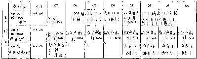
图9D是乐谱数据表316的示范性原理图。图9D所示乐谱数据表316对应于图6所示的示范音乐的“声音2”(第二)行。显然,对其它3行所提供的数据最好相似,并且,所有这4行音乐相应的数据基本上并行地从R0M16a中读出以同时产生4行音乐。在最佳实施例中,乐谱数据表316始于基地址BASE,并包括3个由2个16进制数组成的表项,每个表项用于图6中乐谱所表示每一个音符或休止符。第一个2位16进制数据对应于和音符或休止符的持续时间相符合的持续时间数据表314中的偏移。第二个2位16进制数对应于和所要求音高相符合的频率数据表312中的偏移。最后2位16进制数据(在最佳实施例中,由于只要表示4种状态,实际上可以是1个二进制的数值)指定该声音的“方向”(即,左通道、右通道、双通道或无通道)。FIG. 9D is an exemplary schematic diagram of the score data table 316 . The score data table 316 shown in FIG. 9D corresponds to the "
这样,例如,图6所示“声音2”音乐行的第1小节的第1音符为4分休止符。因此,乐谱数据表316的第一表项说明音长数据表314中的偏移为“02”,对应于4分音符或休止符。乐谱数据表316的第2表项说明频数据表312的零偏移以指定1个休止符(与音符相反)。第1小节第1音符相应的第3和最后表项是数值“01”,指定该声音仅仅准备送到输出声音通道S01而不准备送到输出声音通道S02。Like this, for example, the first note of the first measure of the "
乐谱数据表316提供与旋律或节奏行音符序列对应的这种数据集序列。从而,例如,乐谱数据表316中存储的下面的3个2位16进制数值对应于图6所示“声音2”行的第1小节的第2音符,即E调的4分音符。该数据集的第1个2位16进制数为“02”,指定4分音符音长,对应于音长数据表314中的偏移。该数据集的第2个2位16进制数指定频率数据表312中的偏移“OA”,相当于E音调。该数据集的最后数值对应于声音方向“01”,指定该音符只准备提供给声音输,出通道S01而不准备提供给声音输出通道S02。The score data table 316 provides a sequence of such data sets corresponding to a sequence of notes of a melody or rhythm line. Thus, for example, the following three 2-digit hexadecimal values stored in the score data table 316 correspond to the second note of the first measure in the row "
显然,从而可用图9D所示形式将整个音乐行进行转换并存储在乐谱数据表316中。要“演奏”由该乐谱所表示的音乐,只需以乐谱数据表316中提出的次序读出数据集,参照音长数据表314和频率数据表312,以便将音长和音高信息映射为待装入适当的声音控制寄存器的相应数值,然后,用实际合成数据装入声音寄存器。音符一旦终止,与音乐序列中下一音符对应的数据集可从乐谱数据表316中读出并再次重复整过程以产生下一音符。该整个过程可连续重复直至到达乐谱数据表316的终止(这时,如果愿意,可再次从起始处读取乐谱数据表316,以导致一遍又一遍乐曲的重复)。Obviously, the entire music line can be converted and stored in the score data table 316 in the form shown in FIG. 9D. To "play" the music represented by the score, simply read the data set in the order presented in the score data table 316, refer to the length data table 314 and the frequency data table 312 in order to map the length and pitch information to the Load the corresponding values of the appropriate sound control registers, then load the sound registers with the actual synthesized data. Once the note is terminated, the data set corresponding to the next note in the musical sequence can be read from the score data table 316 and the whole process repeated again to generate the next note. This entire process can be repeated continuously until the end of the score data table 316 is reached (at which point, if desired, the score data table 316 can be read from the beginning again, resulting in a repetition of the song over and over).
图7A和7B一起为实施在图9A所示的程序控制指令310中的示范性程序控制步骤的原理流程图,这些程序步导致对存储在图9D所示乐谱数据表316中音乐行(例子)的声音控制。显然,图7A—7B所示示范性程序控制步的好几个复制的程序最好同时执行(基本上并行)以通过各个的声音发生电路541—544产生多行音乐。换言之,图7A—7B所示的示范性程序控制步只控制单个声音发生电路(例如,电路542)。应由CPU24执行示范性程序步的其它迭代以控制其它声音发生电路(例如,541,543,544)。7A and 7B together are a schematic flow diagram of exemplary program control steps implemented in the
一经启动图7A—7B所示的例程,便得到适当乐谱数据表316的基地址(即,起始地址)并将该基地址写入用于指定特定乐谱数据表的存储器指针寄存器(框350)(显然,在程序ROM16a中可存储1个以上的乐谱数据表316以提供可重现的多个不同的可能的乐段或声响)。然后清除音符跟踪计数器CNT(最好是CPU24内的寄存器或RAM中的单元)并对计时器(例如,图2所示计时器24d)初始化(框352)。起始时,可将该计时器的值置为“01”以便能立即递减并执行所示例程的剩余部分。然后递减计时器(框354)并判定该值是否为零(判定框356)。如该计时器大于零,控制返回框354再次递减计时器,并重复执行框354、356直到该计时器的值递减为零。由框354、356构成的循环对当前音符或休止符的持续时间计数,显然,该计时如果需要的话,可以众所周知的方式用硬件计时器24d驱动的中断。Upon initiation of the routine shown in FIGS. 7A-7B, the base address (i.e., the start address) of the appropriate score data table 316 is obtained and written to the memory pointer register specifying the particular score data table (block 350 ) (obviously, more than one score data table 316 can be stored in the program ROM16a to provide reproducible multiple different possible musical sections or sounds). The note tracking counter CNT (preferably a register within
然后通过将基地址加上当前CNT值来访问在乐谱数据表316中所存储的第1个2位16进制数据,访问程序ROM16a从而读出存储在该单元的内容,并将这些内容存储到称作H的暂存单元(框358)。然后,将H的内容与“FF”值比较,以确定是否已到达乐谱数据表316的结束项(判定框360),(在最佳实施例中,可通过将数值“FF”或其它对音长数据表316无效的偏移来标志该表的结束)。假设H的内容为音长数据表314的有效偏移,那么用H作为从该表的基地址ONPU的偏移计算持续时间数据表中的地址,以合成计算出的地址为地址读出音长数据表314内所存储的内容,并将这些内容装入计时器(框362)。这样,便用待产生的下一音符或休止符的音长来初始化该计时器。该检索值也可装入声音控制寄存器的声音长度数据域(例如NR11位D0—D5)以便使CPU24在到达音符结束项时无须关闭声音发生电路。Then access the first 2-digit hexadecimal data stored in the score data table 316 by adding the base address to the current CNT value, access the
然后递增计数器CNT的数值(框364)以访问乐谱数据表316中下一个2位的16进制数。访问乐谱数据表中的下一单元,(例如,根据基地址和CNT之和计算一地址),读出其内容并将其存储到暂时保存单元Q中(框366)。使用现在存储在暂时保存单元Q的频率数据表312的偏移,用来选址频率数据表312(框368,370)。在最佳实施例中,这时需要读取频率数据表312的两个连续单元,以检索到足以说明存储在例如NR13—NR14中的11位频率数据的信息。从频率数据表312中检索到这些值并将其存储在暂时存储单元X、Y(框368,370),然后对暂存单元X、Y的内容进行测试以判定是否全为零,该全零指出当前待产生的声音为休止符而非音符(判定框372)。如果当前声音为休止符,那么便清除包络初始值寄存器和相应声音发生电路(例如542)的增/减寄存器104、106以禁止声音发生电路产生声音(框374)。另一方面,如果与某音高对应的检索值取代休止符(判定框372的“N”出口),那么便用暂存单元X、Y中存储的值来设置频率设置寄存器84(框376),以确定待产生音符的音高。The counter CNT is then incremented (block 364 ) to access the next 2-digit hexadecimal number in the score data table 316 . Access the next cell in the score data table, (eg, calculate an address based on the sum of the base address and CNT), read its content and store it in temporary storage cell Q (block 366). The frequency data table 312 is accessed using the offset now stored in the frequency data table 312 at temporary storage unit Q (blocks 368, 370). In the preferred embodiment, two consecutive locations of frequency data table 312 need to be read at this point to retrieve sufficient information to account for the 11 bits of frequency data stored, for example, in NR13-NR14. These values are retrieved from the frequency data table 312 and stored in temporary storage locations X, Y (blocks 368, 370), and then the contents of temporary storage locations X, Y are tested to determine whether they are all zeros, which It is indicated that the sound currently to be produced is a rest rather than a note (decision block 372). If the current sound is a rest, then the envelope initial value register and the increment/decrement registers 104, 106 of the corresponding sound generating circuit (eg, 542) are cleared to disable the sound generating circuit from generating sound (block 374). On the other hand, if the search value corresponding to a certain pitch replaces the rest ("N" exit of decision box 372), then the frequency setting register 84 is set with the value stored in the temporary storage unit X, Y (box 376), to determine the pitch of the note to be produced.
然后递增CNT计数器(框378),读出存储在乐谱数据表316中相对应“声音方向”的第3个值(框380)。然后对该检索到的数据进行测试,判定它是否对应于新的输出方向数据(判定框382)。在最佳实施例中,虽然对由乐谱数据表316所定义的所有的每一个音符和休止符清楚地说明了图9D所示的左或右“声音方向”数据,但还是希望(例如,为节省存储器的缘故)只是在与特定声音发生电路对应的声音方向相对于该序列前面音符有所变化时才说明声音方向数据。这样,在最佳实施例中,由于在乐谱数据表316中存储的有些数据集只有2个2位16进制数而不是3个(如果声音方向和上一个所演奏音符相同,则省略该声音方向数据)。图7B所示的判定框382判定是否已读出新的声音方向数据,如已读出,按照由框380所得到的值来设置适当声音控制寄存器的适当位(例如,寄存器NR51位D1、D5),(框384)并递增计数器CNT(框386)以使之指向在乐谱数据表316中所存储的下一数据集的起始处。另一方面,如果由框380读到的值不是新的声音方向数据,那么框386不执行对计数器CNT的递增,并如图7A所示控制返回到框354、356。The CNT counter is then incremented (block 378), and the third value stored in the score data table 316 corresponding to "sound direction" is read (block 380). The retrieved data is then tested to see if it corresponds to new output direction data (decision block 382). In the preferred embodiment, although left or right "sound direction" data as shown in Fig. memory) only accounts for sound direction data when the sound direction corresponding to a particular sound generating circuit has changed relative to previous notes in the sequence. Like this, in the preferred embodiment, since some data sets stored in the score data table 316 have only 2 2-digit hexadecimal numbers instead of 3 (if the sound direction is the same as the last played note, then omit the sound direction data).
一旦控制返回到框354、356,递减计时器对当前音符或休止符计时。一旦该持续时间过去,再次对下一待产生的音符或休止符重复框358—386的处理。Once control returns to blocks 354, 356, the countdown timer clocks the current note or rest. Once the duration has elapsed, the processing of blocks 358-386 is repeated again for the next note or rest to be produced.
图8是图4所示立体声/单声道选择电路202的示意性原理图。选择电路202接收来自放大器60L的左通道声音信号S01和来自放大器60R的右通道声音信号S02,将适当的信号发送给扬声器120或给立体声耳机64。尤其是,如果立体声耳机64插头没有与耳机插座122连接,那么,立体声/单声道选择电路202将左、右通道的声音信号S01、S02混在一起以提供单声道信号,并将该单声道信号加至扬声器120。另一方面,如果立体声耳机64与耳机插座122相连,那么立体声/单声道选择电路202将左通道声音信号S01耦合到耳机的左耳换能器、并把右通道声音信号S02耦合到耳机的右耳换能器。FIG. 8 is a schematic schematic diagram of the stereo/mono selection circuit 202 shown in FIG. 4 . The selection circuit 202 receives the left channel sound signal S01 from the
在最佳实施例中,如图4所示的放大器60L的输出通过串联电阻112L耦合到放大器114L的输入端,类似地,将图4所示的放大器60R的输出通过串联电阻112R耦合到放大器114R的输入端。电阻116L、116R串联跨接在放大器114L、114R的输入端。连接电阻116L、116R的结点与单声道放大器118的输入端耦合。电阻116L、116R的作用是将S01和S02信号混合在一起并将导出的混合(单声道)信号提供给放大器118。放大器118驱动扬声器120。In the preferred embodiment, the output of
耳机插座122包括左通道声频触点122L、右通道声频触点122R和一对开关触点122P。与耳机124耦合的耳机插头124预定由耳机插座122接受和匹配。耳机插座122例如可以是与作为插入式配合件的耳机插头124相配合的凹形配合件。这样,耳机插头124便可插入耳机插座122以便将耳机64与放大器114L、114R的输出端相连接,并可在以后从该插座上移去该插头从而使耳机与放大器断开。例如,有时用户可能希望用耳机64收听由声音发生框58所产生的声音(这时,耳机插头124可插入插座122)。在另一些时候,用户可能不希望使用耳机而将耳机插头124从耳机插座122拔出(以便用扬声器120而不是用耳机64来收听声音)。The
耳机插头124包括左通道触点124L和右通道触点124R,当插头与插座配合时,右通道触点124L与耳机插头的左通道声频触点112L形成电接触,同时,右通道触点124R与耳机插头左通道声频触点112R形成电接触。接地部分124G最好与地相接。插头的左通道触点124L通过左通道导线126L连接到耳机64的左通道换能器,而插头右通道触点124R通过右通道导线126R连接到耳机64的右通道换能器。The
每当将耳机插头124插入耳机插座124时,触点122P便相互接触形成地与反向放大器130和非反相放大器132的输入端之间的电连接。该地连接使得反相放大器130产生逻辑电平“1”的信号,使用该信号允许放大器114L、114R工作。该接地连接也使得非反相放大器132产生逻辑电平“0”的信号用来禁止放大器118工作。在这种状态下,由放大器114L、114R将立体声信号通过触点122L、122R和124L、124R供给耳机64并禁止扬声器120。Whenever the
另一方面,一旦耳机插头124与耳机插座122断连,触点112P不再彼此相连。与电源电动势相连的上拉电阻128将反向放大器130的输入和非反相放大器132的输入上拉到逻辑电平“1”。该逻辑电平的高电平使得反向放大器130交逻辑电平“0”信号加到放大器114R、114L(由此来禁止这两个放大器工作)并使得非反向放大器132将逻辑电平“1”信号加到放大器118(由此允许该放大器工作)。在这种情况下,由放大器118合成(混合)出单声道信号并加到扬声器120。由于耳机未与座相连、放大器114L、114R没有将信号加到耳机插座触点112L、112R。On the other hand, once the
尽管结合目前认为是最实用和最佳的实施例描述了本发明,但可以理解,本发明不局限于所公开的实施例,而相反,本发明旨在覆盖包含在所附权利要求的精神和范围内的各种变型及等价结构。While the invention has been described in connection with what are presently considered to be the most practical and best embodiments, it is to be understood that the invention is not limited to the disclosed embodiments, but on the contrary, the invention is intended to cover the spirit and scope of the invention contained in the appended claims. Variations and equivalent structures within the range.
Claims (9)
Priority Applications (1)
| Application Number | Priority Date | Filing Date | Title |
|---|---|---|---|
| CN 93104372 CN1106209C (en) | 1989-01-10 | 1993-04-24 | Electronic gaming device with pseude-stereophonic sound generating cap abilities |
Applications Claiming Priority (5)
| Application Number | Priority Date | Filing Date | Title |
|---|---|---|---|
| JP4453/89 | 1989-01-10 | ||
| JP2007/89 | 1989-01-10 | ||
| JP1004453A JPH02184200A (en) | 1989-01-10 | 1989-01-10 | Pseudo stereo sound generator |
| JP101027/89 | 1989-04-20 | ||
| JP1101027A JP2878306B2 (en) | 1989-04-20 | 1989-04-20 | Memory cartridge |
Related Child Applications (1)
| Application Number | Title | Priority Date | Filing Date |
|---|---|---|---|
| CN 93104372 Division CN1106209C (en) | 1989-01-10 | 1993-04-24 | Electronic gaming device with pseude-stereophonic sound generating cap abilities |
Publications (2)
| Publication Number | Publication Date |
|---|---|
| CN1044199A CN1044199A (en) | 1990-07-25 |
| CN1031376C true CN1031376C (en) | 1996-03-20 |
Family
ID=26338222
Family Applications (1)
| Application Number | Title | Priority Date | Filing Date |
|---|---|---|---|
| CN 90100211 Expired - Fee Related CN1031376C (en) | 1989-01-10 | 1990-01-10 | Electronic game device capable of producing pseudo-stereo sound |
Country Status (1)
| Country | Link |
|---|---|
| CN (1) | CN1031376C (en) |
Families Citing this family (3)
| Publication number | Priority date | Publication date | Assignee | Title |
|---|---|---|---|---|
| SE0202159D0 (en) * | 2001-07-10 | 2002-07-09 | Coding Technologies Sweden Ab | Efficientand scalable parametric stereo coding for low bitrate applications |
| JP3827693B2 (en) * | 2004-09-22 | 2006-09-27 | 株式会社コナミデジタルエンタテインメント | GAME DEVICE, GAME DEVICE CONTROL METHOD, AND PROGRAM |
| CN107493558B (en) * | 2017-09-07 | 2019-01-15 | 维沃移动通信有限公司 | A kind of voice signal control method and mobile terminal |
-
1990
- 1990-01-10 CN CN 90100211 patent/CN1031376C/en not_active Expired - Fee Related
Also Published As
| Publication number | Publication date |
|---|---|
| CN1044199A (en) | 1990-07-25 |
Similar Documents
| Publication | Publication Date | Title |
|---|---|---|
| US5095798A (en) | Electronic gaming device with pseudo-stereophonic sound generating capabilities | |
| US8821287B2 (en) | Video game display system | |
| US6972363B2 (en) | Systems and methods for creating, modifying, interacting with and playing musical compositions | |
| US6563038B2 (en) | Karaoke system | |
| CN1912990A (en) | Performance apparatus and tone generation method therefor | |
| CN1151420C (en) | Method of reducing power consumption and portable electronic device using the method | |
| CN1031376C (en) | Electronic game device capable of producing pseudo-stereo sound | |
| HK1050101A1 (en) | Tone generator apparatus sharing parameters among channels | |
| JP2001137415A (en) | Dance game device | |
| CN1106209C (en) | Electronic gaming device with pseude-stereophonic sound generating cap abilities | |
| US20070238500A1 (en) | System and method for simultaneously playing games and audio-visual content | |
| CN1178200C (en) | Method, device and entertainment system for producing playback sound | |
| HK1005201B (en) | Electronic gaming device with pseudo-stereophonic sound generating capabilities | |
| JP3757712B2 (en) | Performance learning data transmission apparatus and computer-readable recording medium recording performance learning data transmission processing program | |
| KR100518140B1 (en) | Apparatus for selecting tone color for electric musical instrument and method therefor | |
| US20090275409A1 (en) | Game machine, game system, and computer-readable storage medium | |
| JP2008122888A (en) | Karaoke machine | |
| JP4373354B2 (en) | Music player | |
| CN120636351A (en) | Portable electronic music synthesizer | |
| JP2004348035A (en) | Karaoke toy cartridge | |
| CN115211134A (en) | Loudspeaker | |
| JPH10143178A (en) | Music performance system | |
| JP2003108163A (en) | Karaoke microphone device | |
| HK1050416A1 (en) | Portable phone equipped with composing function | |
| CN1905003A (en) | Musical performance device and musical tone generation method using the musical performance device |
Legal Events
| Date | Code | Title | Description |
|---|---|---|---|
| C06 | Publication | ||
| PB01 | Publication | ||
| C10 | Entry into substantive examination | ||
| SE01 | Entry into force of request for substantive examination | ||
| C14 | Grant of patent or utility model | ||
| GR01 | Patent grant | ||
| C15 | Extension of patent right duration from 15 to 20 years for appl. with date before 31.12.1992 and still valid on 11.12.2001 (patent law change 1993) | ||
| OR01 | Other related matters | ||
| EE01 | Entry into force of recordation of patent licensing contract |
Assignee: Ique (China) Co. Ltd. Assignor: Nintendo Co., Ltd. Contract fulfillment period: The period of performance of the contract is 2004-05-01 to the contract period Contract record no.: Contract filing No. 041000030075 Denomination of invention: An electronic game device capable of producing pseudo stereo sounds Granted publication date: 19960320 License type: Exclusive license Record date: 20040818 |
|
| LIC | Patent licence contract for exploitation submitted for record |
Free format text: EXCLUSIVE LICENCE; TIME LIMIT OF IMPLEMENTING CONTACT:2004-05-01 TO CONTRACT Name of requester: SHENYOU TECHNOLOGY( CHINA) CO., LTD. Effective date: 20040818 |
|
| C19 | Lapse of patent right due to non-payment of the annual fee | ||
| CF01 | Termination of patent right due to non-payment of annual fee |