CN103080461A - Optimization of vacuum systems and methods for drying drilling cuttings - Google Patents
Optimization of vacuum systems and methods for drying drilling cuttings Download PDFInfo
- Publication number
- CN103080461A CN103080461A CN2010800667119A CN201080066711A CN103080461A CN 103080461 A CN103080461 A CN 103080461A CN 2010800667119 A CN2010800667119 A CN 2010800667119A CN 201080066711 A CN201080066711 A CN 201080066711A CN 103080461 A CN103080461 A CN 103080461A
- Authority
- CN
- China
- Prior art keywords
- drilling
- vacuum
- slurry
- screen
- cuttings
- Prior art date
- Legal status (The legal status is an assumption and is not a legal conclusion. Google has not performed a legal analysis and makes no representation as to the accuracy of the status listed.)
- Granted
Links
Images


Classifications
-
- B—PERFORMING OPERATIONS; TRANSPORTING
- B01—PHYSICAL OR CHEMICAL PROCESSES OR APPARATUS IN GENERAL
- B01D—SEPARATION
- B01D33/00—Filters with filtering elements which move during the filtering operation
- B01D33/70—Filters with filtering elements which move during the filtering operation having feed or discharge devices
- B01D33/74—Filters with filtering elements which move during the filtering operation having feed or discharge devices for discharging filtrate
- B01D33/745—Construction of suction casings, pans, or the like
-
- B—PERFORMING OPERATIONS; TRANSPORTING
- B01—PHYSICAL OR CHEMICAL PROCESSES OR APPARATUS IN GENERAL
- B01D—SEPARATION
- B01D33/00—Filters with filtering elements which move during the filtering operation
- B01D33/01—Filters with filtering elements which move during the filtering operation with translationally moving filtering elements, e.g. pistons
- B01D33/03—Filters with filtering elements which move during the filtering operation with translationally moving filtering elements, e.g. pistons with vibrating filter elements
- B01D33/0346—Filters with filtering elements which move during the filtering operation with translationally moving filtering elements, e.g. pistons with vibrating filter elements with flat filtering elements
- B01D33/0353—Filters with filtering elements which move during the filtering operation with translationally moving filtering elements, e.g. pistons with vibrating filter elements with flat filtering elements self-supporting
-
- B—PERFORMING OPERATIONS; TRANSPORTING
- B01—PHYSICAL OR CHEMICAL PROCESSES OR APPARATUS IN GENERAL
- B01D—SEPARATION
- B01D19/00—Degasification of liquids
- B01D19/0073—Degasification of liquids by a method not covered by groups B01D19/0005 - B01D19/0042
-
- B—PERFORMING OPERATIONS; TRANSPORTING
- B01—PHYSICAL OR CHEMICAL PROCESSES OR APPARATUS IN GENERAL
- B01D—SEPARATION
- B01D33/00—Filters with filtering elements which move during the filtering operation
- B01D33/01—Filters with filtering elements which move during the filtering operation with translationally moving filtering elements, e.g. pistons
- B01D33/03—Filters with filtering elements which move during the filtering operation with translationally moving filtering elements, e.g. pistons with vibrating filter elements
- B01D33/0346—Filters with filtering elements which move during the filtering operation with translationally moving filtering elements, e.g. pistons with vibrating filter elements with flat filtering elements
- B01D33/0376—Filters with filtering elements which move during the filtering operation with translationally moving filtering elements, e.g. pistons with vibrating filter elements with flat filtering elements supported
-
- B—PERFORMING OPERATIONS; TRANSPORTING
- B01—PHYSICAL OR CHEMICAL PROCESSES OR APPARATUS IN GENERAL
- B01D—SEPARATION
- B01D33/00—Filters with filtering elements which move during the filtering operation
- B01D33/80—Accessories
- B01D33/801—Driving means, shaft packing systems or the like
-
- B—PERFORMING OPERATIONS; TRANSPORTING
- B07—SEPARATING SOLIDS FROM SOLIDS; SORTING
- B07B—SEPARATING SOLIDS FROM SOLIDS BY SIEVING, SCREENING, SIFTING OR BY USING GAS CURRENTS; SEPARATING BY OTHER DRY METHODS APPLICABLE TO BULK MATERIAL, e.g. LOOSE ARTICLES FIT TO BE HANDLED LIKE BULK MATERIAL
- B07B1/00—Sieving, screening, sifting, or sorting solid materials using networks, gratings, grids, or the like
- B07B1/28—Moving screens not otherwise provided for, e.g. swinging, reciprocating, rocking, tilting or wobbling screens
-
- B—PERFORMING OPERATIONS; TRANSPORTING
- B07—SEPARATING SOLIDS FROM SOLIDS; SORTING
- B07B—SEPARATING SOLIDS FROM SOLIDS BY SIEVING, SCREENING, SIFTING OR BY USING GAS CURRENTS; SEPARATING BY OTHER DRY METHODS APPLICABLE TO BULK MATERIAL, e.g. LOOSE ARTICLES FIT TO BE HANDLED LIKE BULK MATERIAL
- B07B13/00—Grading or sorting solid materials by dry methods, not otherwise provided for; Sorting articles otherwise than by indirectly controlled devices
- B07B13/14—Details or accessories
- B07B13/16—Feed or discharge arrangements
-
- E—FIXED CONSTRUCTIONS
- E21—EARTH OR ROCK DRILLING; MINING
- E21B—EARTH OR ROCK DRILLING; OBTAINING OIL, GAS, WATER, SOLUBLE OR MELTABLE MATERIALS OR A SLURRY OF MINERALS FROM WELLS
- E21B21/00—Methods or apparatus for flushing boreholes, e.g. by use of exhaust air from motor
- E21B21/06—Arrangements for treating drilling fluids outside the borehole
- E21B21/063—Arrangements for treating drilling fluids outside the borehole by separating components
- E21B21/065—Separating solids from drilling fluids
-
- F—MECHANICAL ENGINEERING; LIGHTING; HEATING; WEAPONS; BLASTING
- F26—DRYING
- F26B—DRYING SOLID MATERIALS OR OBJECTS BY REMOVING LIQUID THEREFROM
- F26B20/00—Combinations of machines or apparatus covered by two or more of groups F26B9/00 - F26B19/00
-
- F—MECHANICAL ENGINEERING; LIGHTING; HEATING; WEAPONS; BLASTING
- F26—DRYING
- F26B—DRYING SOLID MATERIALS OR OBJECTS BY REMOVING LIQUID THEREFROM
- F26B5/00—Drying solid materials or objects by processes not involving the application of heat
- F26B5/12—Drying solid materials or objects by processes not involving the application of heat by suction
-
- B—PERFORMING OPERATIONS; TRANSPORTING
- B01—PHYSICAL OR CHEMICAL PROCESSES OR APPARATUS IN GENERAL
- B01D—SEPARATION
- B01D2201/00—Details relating to filtering apparatus
- B01D2201/20—Pressure-related systems for filters
- B01D2201/204—Systems for applying vacuum to filters
Landscapes
- Engineering & Computer Science (AREA)
- Life Sciences & Earth Sciences (AREA)
- Chemical Kinetics & Catalysis (AREA)
- Chemical & Material Sciences (AREA)
- Mechanical Engineering (AREA)
- Mining & Mineral Resources (AREA)
- Geology (AREA)
- General Engineering & Computer Science (AREA)
- Molecular Biology (AREA)
- Physics & Mathematics (AREA)
- Environmental & Geological Engineering (AREA)
- Fluid Mechanics (AREA)
- Health & Medical Sciences (AREA)
- General Life Sciences & Earth Sciences (AREA)
- Geochemistry & Mineralogy (AREA)
- Separation Of Solids By Using Liquids Or Pneumatic Power (AREA)
- Drying Of Solid Materials (AREA)
- Degasification And Air Bubble Elimination (AREA)
- Vaporization, Distillation, Condensation, Sublimation, And Cold Traps (AREA)
- Combined Means For Separation Of Solids (AREA)
- Tents Or Canopies (AREA)
- Paper (AREA)
- Filtration Of Liquid (AREA)
- Earth Drilling (AREA)
- Processing Of Stones Or Stones Resemblance Materials (AREA)
- Processing And Handling Of Plastics And Other Materials For Molding In General (AREA)
Abstract
Description
技术领域technical field
本发明描述了用于从钻探切削物中分离出浆料的系统和方法。具体而言,本发明涉及并入真空系统的振荡器以及操作此类系统以实现高度浆料分离的方法。所述系统和方法在多种筛孔尺寸、真空气流以及真空设计中都是有效的。Systems and methods for separating slurry from drilling cuttings are described. In particular, the present invention relates to oscillators incorporated into vacuum systems and methods of operating such systems to achieve a high degree of slurry separation. The systems and methods are effective across a variety of mesh sizes, vacuum airflows, and vacuum designs.
背景技术Background technique
钻探浆料的损失给能源勘探行业提出了若干技术上的和成本上的挑战。这些挑战通常包括钻探浆料渗入到形成物的渗流损失、表面上的钻探浆料的回收及/或被钻探浆料污染的钻探岩屑或切削物的处理。在本发明的范围内,“钻探浆料”既包括在表面处预备的以未变更的状态来使用的用于钻探的浆料,也包括从井中所回收的所有浆料,这些浆料可包括来自井中的多种污染物,包括水以及碳氢化合物。Loss of drilling slurry presents several technical and cost challenges to the energy exploration industry. These challenges typically include seepage losses of drilling slurry infiltration into formations, recovery of drilling slurry on the surface, and/or disposal of drilling cuttings or cuttings contaminated with drilling slurry. Within the scope of the present invention, "drilling slurry" includes both slurry prepared at the surface for use in an unaltered state for drilling and all slurry recovered from the well, which may include Various contaminants from the well, including water as well as hydrocarbons.
业已知晓并且作为技术背景来给出,在挖掘或钻探过程中,在钻探项目的整个过程中钻探浆料损失可达到接近300立方米的损失的钻探浆料的水平。由于一些钻探浆料具有超过1600美元每立方米的价值,此类浆料的损失对钻探操作者来说意味着非常高的成本。钻探浆料通常可被划分为“基于水的”或“基于油的”钻探浆料,这些钻探浆料包括所属领域的技术人员所熟知的许多昂贵并且特有的化学品。因此,期望在钻探项目中钻探浆料的浪费的量最小,于是采用多种技术来将在井下和表面处的钻探浆料的损失最小化。此外,在一些地区,为配制钻探浆料而输送油或水对于一些操作而言可具有若干成本上的挑战,特别是在沙漠、近海处以及甚至在民众不允许分配水来用于此用途的一些地区。It is known and given as technical background that during excavation or drilling drilling slurry losses can reach levels close to 300 cubic meters of lost drilling slurry throughout the course of a drilling project. Since some drilling slurries have a value in excess of $1600 per cubic meter, the loss of such slurries represents a very high cost to drilling operators. Drilling slurries can generally be classified as "water-based" or "oil-based" drilling slurries, which include a number of expensive and proprietary chemicals well known to those skilled in the art. Accordingly, it is desirable to minimize the amount of wasted drilling fluid during a drilling program, and various techniques are employed to minimize the loss of drilling fluid both downhole and at the surface. In addition, in some regions, transporting oil or water to make drilling slurry can present several cost challenges for some operations, especially in deserts, offshore, and even where the population does not allow the distribution of water for this purpose some areas.
如上文所述,一个具体的问题是将钻探浆料以及任何碳氢化合物从可能在表面处粘附到钻探切削物的形成物(统称为“浆料”)中分离出来。已通过各种技术来达成从钻探切削物有效分离各种浆料,所述技术包括但不限于,水力旋流器、泥浆清洁器、线性运动振荡器、螺旋推进式离心机、立式篮式离心机(VBC)、真空器件,以及涡流分离器。如所属领域的技术人员所熟知,这些器件通常以每天1000-2000美元的价格出租,因此,对操作者构成显著的成本。因此,浆料的回收对补偿这些费用是必要的,这就要求回收的浆料的价值大于设备的租赁费用从而使回收技术在经济上更合理。在大量高成本的钻探浆料被损失(例如,超过3立方米每天)的挖掘工程中,专用分离设备的日常租赁收费可提供有利的经济效益。此外,操作者很可能在其钻探浆料/钻探切削物分离/回收系统的设计中将对环境的影响及/或被钻探浆料污染的钻探切削物的处理成本作为考虑因素。As noted above, a particular problem is separating the drilling slurry and any hydrocarbons from formations (collectively "slurry") that may adhere to the drilling cuttings at the surface. Efficient separation of various slurries from drilling cuttings has been achieved by various techniques including, but not limited to, hydrocyclones, mud cleaners, linear motion shakers, propeller centrifuges, vertical basket Centrifuges (VBC), vacuum devices, and vortex separators. As is well known to those skilled in the art, these devices are typically leased for $1000-2000 per day and thus represent a significant cost to the operator. Therefore, slurry recovery is necessary to compensate for these costs, which requires that the value of the recovered slurry be greater than the rental cost of the equipment to make the recovery technology more economically sound. In excavations where large amounts of costly drilling slurry are lost (eg, more than 3 cubic meters per day), daily rental charges for dedicated separation equipment can provide favorable economics. In addition, operators are likely to factor in the environmental impact and/or the cost of disposal of drilling slurry-contaminated drilling cuttings in the design of their drilling slurry/drill cuttings separation/recovery systems.
另外,用于从钻探切削物中分离钻探浆料的以往技术也使用液体喷淋系统来在钻探切削物在振荡器设备上经受处理时将“清洗”液输送到钻探切削物中。在切削物在振荡器上经受处理时此类清洗液以及关联的流体供应系统用来输送多种清洗流体,并且根据所处理的钻探浆料的类型,可包括多种类型的设计来输送不同的清洗流体。例如,根据在振荡器上所处理的钻探浆料和钻探切削物,清洗液可包含油、水或乙二醇。通常,应用这些清洗流体来减少粘附到切削物上的浆料的粘度及/或表面张力并且允许对更多的浆料进行回收。然而,通常这些技术对许多钻探浆料而言都不具有成本效益,因为稀释流体的使用通常造成不可接受的钻探浆料体积的增加及/或化学稳定性的改变,并且因此造成钻探浆料流变学性质的改变。In addition, prior art for separating drilling slurry from drilling cuttings has also used a liquid spray system to deliver a "cleaning" fluid into the drilling cuttings as they are being processed on a shaker device. Such cleaning fluids and associated fluid supply systems are used to deliver a variety of cleaning fluids while the cuttings are being processed on the shaker and may include various types of designs to deliver different cleaning fluids depending on the type of drilling slurry being processed. cleaning fluid. For example, the cleaning fluid may contain oil, water or glycol depending on the drilling slurry and drilling cuttings being processed on the shaker. Typically, these cleaning fluids are applied to reduce the viscosity and/or surface tension of the slurry adhering to the cuttings and allow more slurry to be recovered. However, these techniques are generally not cost-effective for many drilling slurries because the use of dilution fluids often results in an unacceptable increase in the volume of the drilling slurry and/or a change in the chemical stability and thus the flow of the drilling slurry. Changes in the nature of variability.
因此,虽然有多种分离系统通常能够有效及/或有效率地达成一定水平的浆料/切削物分离,但是每种形式的分离技术通常只在一定范围内的条件或参数下并且在特定的价位上才能有效率地操作。例如,利用筛网的标准振荡器能够相对有效率并且持续地从切削物中移除一定量的钻探浆料,在振荡器的通常操作中操作者通常能够使钻探浆料/切削物分离达到浆料相对于钻探切削物为12-40重量%的水平(即,所回收切削物的总质量的12-40%为钻探浆料)。浆料/切削物重量%的范围通常由筛孔尺寸来控制,其中通过使用较大的筛孔(例如,50目至75目),操作者可实现较高程度的浆料/切削物分离,通过使用较小的筛孔(例如,最高325目)来实现较低程度的浆料/切削物分离。由于筛网网眼尺寸影响了通过筛网的固体量,所以须在使用大目筛网与小目筛网之间作出取舍。也就是说,虽然操作者能够通过使用较大目筛网(50目至75目)来降低在从振荡器脱落的切削物上保留的浆料,但是使用较大目筛网的问题是实质上更大量的固体将会通过筛网,随后会显著地影响所回收浆料的流变学和密度及/或需要使用额外的有可能效率不高的分离技术来将这些固体从所回收的钻探浆料中移除。相反,使用小目筛网,虽然有可能将对于用于从所回收钻探浆料移除固体的进一步下游分离技术的需要降为最低,但会实质上导致较大量的钻探浆料未被回收,因为这些钻探浆料更有可能经过筛网并因此导致更大的钻探浆料损失,以及/或者需要后续的处理。Thus, while a variety of separation systems are generally effective and/or efficient at achieving some level of slurry/cuttings separation, each form of separation technology is typically only available within a range of conditions or parameters and within specific Only at the price can we operate efficiently. For example, a standard shaker utilizing a screen is capable of relatively efficiently and consistently removing a certain amount of drilling slurry from the cuttings, and during normal operation of the shaker the operator is usually able to achieve a drilling slurry/cutting separation of up to The slurry is at a level of 12-40% by weight relative to the drilling cuttings (ie, 12-40% of the total mass of the recovered cuttings is drilling slurry). The range of stock/cutting weight % is usually controlled by the mesh size, where by using larger mesh (eg, 50 mesh to 75 mesh), the operator can achieve a higher degree of stock/cutting separation, A lower degree of slurry/cuttings separation is achieved by using smaller screen openings (eg, up to 325 mesh). Because the screen mesh size affects the amount of solids that pass through the screen, a trade-off must be made between using a large mesh screen versus a small mesh screen. That is, while operators can reduce the amount of slurry retained on cuttings falling off the shaker by using larger mesh screens (50 mesh to 75 mesh), the problem with using larger mesh screens is that they are substantially Larger quantities of solids will pass through the screen, which can then significantly affect the rheology and density of the recovered slurry and/or require the use of additional, possibly inefficient separation techniques to separate these solids from the recovered drilling fluid. removed from the feed. Conversely, the use of small mesh screens, while potentially minimizing the need for further downstream separation techniques to remove solids from the recovered drilling slurry, results in substantially greater amounts of drilling slurry not being recovered, Because these drilling muds are more likely to pass through the screen and thus result in greater drilling mud loss and/or require subsequent treatment.
相应地,在许多操作中,操作者会通过离心力类型的器件调节从振荡器中所回收的浆料使其经受额外的处理,从而在回收或再生钻探浆料之前减小浆料密度并且移除尽可能多的微细固体。然而,此类调节需要更为昂贵的设备,例如离心机、滚动离心机、水力旋流器等,它们会增加回收总成本。这些处理技术也被其所处理的浆料的质量所直接影响,因此由使用粗筛网的振荡器预处理的浆料将不如从较微细筛网接收的浆料,后者更为优化。Accordingly, in many operations operators will condition the slurry recovered from the shaker by means of a centrifugal force type device to subject it to additional processing to reduce the slurry density and remove the as many fine solids as possible. However, such conditioning requires more expensive equipment, such as centrifuges, rolling centrifuges, hydrocyclones, etc., which increase the overall cost of recovery. These treatment techniques are also directly affected by the quality of the stock they process, so stock pretreated by a shaker using a coarse screen will not be as optimal as stock received from a finer screen.
此外,离心机和水力旋流器以及其他设备的性能也受到进料浆料的粘度和密度的直接影响。因此,将重且充满固体的浆料输送到二级处理设备的钻探浆料回收技术需要力度更强的技术(例如增加的重力及/或真空)来实现分离,而这通常会导致钻探切削物的破碎。In addition, the performance of centrifuges and hydrocyclones, among other equipment, is directly affected by the viscosity and density of the feed slurry. Consequently, drilling slurry recovery techniques that transport heavy, solids-laden slurry to secondary processing facilities require more aggressive techniques (such as increased gravity and/or vacuum) to achieve separation, which often results in drilling cuttings broken.
因此,操作者会试图将钻探浆料损失的成本,与所回收的浆料的质量,连同其他的考虑因素一起衡量。虽然操作者通常对切削物处理的质量以及可用的浆料回收技术没有多少选择余地,但是许多操作者将操作分离设备,使得从分离设备所回收的钻探浆料密度会比系统中的循环浆料的密度重大约200-300kg/m3。当这种含有显著量的微细固体的较重浆料被留在钻探浆料中时将会立刻或在一段时间后破坏钻探浆料或其他任何类型浆料的性能。Accordingly, operators will attempt to weigh the cost of drilling mud loss against the quality of the mud recovered, among other considerations. While operators typically have little choice in the quality of cuttings treatment and slurry recovery techniques available, many operators will operate separation equipment such that the drilling slurry recovered from the separation equipment will be denser than the circulating slurry in the system. The density weighs about 200-300kg/m 3 . When such a heavy slurry containing a significant amount of fine solids is left in the drilling slurry it will destroy the performance of the drilling slurry or any other type of slurry either immediately or after a period of time.
因此,依然需要能经济地增大从振荡器中所回收的浆料的体积,且不会不利地影响所回收的钻探浆料的流变学性质的系统。具体而言,需要这样的分离系统,其可使所回收的浆料密度相对于原始浆料密度处于5-100kg/m3的范围内,并且不影响塑性粘度、胶凝强度等流变学性质。Accordingly, there remains a need for a system that can economically increase the volume of slurry recovered from a shaker without adversely affecting the rheological properties of the recovered drilling slurry. Specifically, there is a need for a separation system that enables the recovered pulp to have a density in the range of 5-100 kg/ m3 relative to the original pulp density without affecting rheological properties such as plastic viscosity and gel strength .
此外,需要开发低成本的改装技术,所述技术可强化浆料回收并且以当前所采用的机制和技术的成本中的一部分来完成。Furthermore, there is a need to develop low-cost retrofit techniques that can enhance slurry recovery and do so at a fraction of the cost of currently employed mechanisms and techniques.
真空技术的使用是改善钻探浆料分离的一个解决方案。然而,真空技术本身具有多种问题,包括不充分的切削物/浆料分离,如上所述,其需要额外且昂贵的下游处理,并且其不能从所回收的钻探浆料中有效地移除细粒,从而增大了所回收的钻探浆料的密度。此外,力度强的真空系统也将使切削物破碎从而使生成细粒的问题增大。The use of vacuum technology is one solution to improve drilling slurry separation. However, vacuum technology itself has several problems including insufficient cuttings/slurry separation, which requires additional and expensive downstream processing as mentioned above, and its inability to effectively remove fines from the recovered drilling mud. particles, thereby increasing the density of the recovered drilling slurry. In addition, a strong vacuum system will also break up the cuttings and increase the problem of fines.
此外,在工作场所中多种真空技术还可能出现尘埃和薄雾问题,例如使用过去的真空技术,需要用高压冲洗来定期地清理堵塞的筛网。筛网的高压冲洗对操作者造成了空气中传播的尘埃以及薄雾的危害。因此,仍然需要能将对筛网的清洗的需求最小化的技术。Additionally, dust and mist can be a problem with many vacuum technologies in the workplace, for example with past vacuum technologies requiring high pressure washing to periodically clear clogged screens. The high-pressure flushing of the screen creates an airborne dust and mist hazard for the operator. Accordingly, there remains a need for techniques that minimize the need for cleaning of the screen.
此外,在真空筛网的下侧需要改善的浆料分离系统,其允许被吸入穿过真空筛网的相对较大体积的空气与被吸入穿过真空筛网的相对较小体积的钻探浆料有效地并且有效率地分离。也就是说,需要改善的浆料/空气分离系统。还需要在钻探浆料中协助脂肪酸氧化的真空技术,从而减少对额外乳化剂的需要。Furthermore, there is a need for an improved slurry separation system on the underside of the vacuum screen that allows a relatively large volume of air to be drawn through the vacuum screen with a relatively small volume of drilling slurry to be drawn through the vacuum screen Effectively and efficiently separate. That is, there is a need for improved slurry/air separation systems. There is also a need for vacuum technology that assists in the oxidation of fatty acids in drilling slurries, thereby reducing the need for additional emulsifiers.
在操作上,还需要改善的操作真空系统的方法,所述方法有效地使筛网堵塞的风险最小化并且能够使用更微细的筛网。Operationally, there is also a need for improved methods of operating vacuum systems that effectively minimize the risk of screen clogging and enable the use of finer screens.
此外,需要系统既允许有效率地替换筛网,还能提供在真空系统与筛网之间的改善的垫圈与密封。Furthermore, there is a need for a system that allows for efficient replacement of the screen while also providing an improved gasket and seal between the vacuum system and the screen.
现有技术回顾Review of prior art
对现有技术的回顾揭示了包括真空技术的多种技术在以前已用于从钻探切削物中分离钻探流体,这些技术包括振动振荡器。A review of the prior art revealed that a variety of techniques including vacuum techniques, including vibratory oscillators, have previously been used to separate drilling fluid from drilling cuttings.
例如,美国专利第4,350,591号描述了钻探泥浆清洁装置,所述装置具有倾斜的传送带筛网(travelling belt screen)以及包括排风罩和鼓风机的脱气装置。美国专利公开案第2008/0078700号揭示了具有用于清洁筛网的改装喷淋喷嘴的自清洁振动振荡器。加拿大专利申请案第2,664,173号描述了具有压力差分系统的振荡器,所述压力差分系统在整个筛网上施加非连续的压力,并且包括美国专利第6,092,390号、美国专利第6,170,580号、美国专利公开案第2006/0113220号以及PCT公开案第2005/054623号的其他现有技术描述了多种分离技术。For example, US Patent No. 4,350,591 describes a drilling mud cleaning apparatus having an inclined traveling belt screen and a degassing apparatus including an exhaust hood and a blower. US Patent Publication No. 2008/0078700 discloses a self-cleaning vibratory oscillator with retrofit spray nozzles for cleaning screens. Canadian Patent Application No. 2,664,173 describes an oscillator with a pressure differential system that applies discontinuous pressure across the screen, and includes U.S. Patent No. 6,092,390, U.S. Patent No. 6,170,580, U.S. Patent Publication Various separation techniques are described in PCT Publication No. 2006/0113220 and other prior art PCT Publication No. 2005/054623.
因此,虽然以前的技术可在一定程度上有效促使钻探浆料/切削物分离,但是对于能够使浆料移除达到实质改善水平的分离器件的设计及操作方面,现有技术无能为力。具体而言,对于达成浆料在切削物上保留的水平低于约12重量%并且对所回收的钻探浆料的密度不具有负面影响而言,现有技术无能为力。Thus, while prior art has been effective in facilitating drilling slurry/cutting separation to some extent, it has failed to address the design and operation of separation devices that would provide substantially improved levels of slurry removal. In particular, the prior art is incapable of achieving a level of slurry retention on cuttings of less than about 12% by weight without negatively impacting the density of the recovered drilling slurry.
发明内容Contents of the invention
本发明描述了用于从钻探切削物中分离钻探浆料的系统和方法,包括改善的真空系统。The present invention describes systems and methods for separating drilling slurry from drilling cuttings, including improved vacuum systems.
在第一项实施例中,提供用于改善在振荡器上进行的对钻探浆料从钻探切削物中的装置,所述装置包含:具有上侧和下侧的振荡器筛网,所述振荡器筛网用于在振荡器内支撑被钻探浆料所污染的钻探切削物;空气真空系统,所述空气真空系统操作性连接到振荡器筛网的一部分用于将有效体积的空气拉过振荡器筛网的该部分以强化穿过振荡器筛网的该部分的钻探浆料的流动以及钻探浆料从钻探切削物中的分离;以及钻探浆料收集系统,所述钻探浆料收集系统用于从筛网和空气真空系统的下侧收集所分离的钻探浆料,其中空气真空系统将一定体积的空气吸过筛网从而将对钻探切削物的破坏最小化,并同时增大了从钻探切削物中所移除的钻探浆料的量并且保持离开振荡器的钻探切削物的有效流动。In a first embodiment, an apparatus for improving removal of drilling slurry from drilling cuttings on a shaker is provided, the apparatus comprising: a shaker screen having an upper side and a lower side, the oscillating a shaker screen for supporting drilling cuttings contaminated with drilling slurry within the shaker; an air vacuum system operatively connected to a portion of the shaker screen for pulling an effective volume of air through the shaker the portion of the shaker screen to enhance the flow of drilling slurry through the portion of the shaker screen and the separation of the drilling slurry from the drilling cuttings; and a drilling slurry collection system for To collect the separated drilling slurry from the underside of the screen and air vacuum system, wherein the air vacuum system sucks a certain volume of air through the screen to minimize the damage to the drilling cuttings and at the same time increase the The amount of drilling slurry removed in the cuttings and maintains an efficient flow of drilling cuttings away from the oscillator.
在多项实施例中,本发明提供了额外的功能和结构。In various embodiments, the present invention provides additional functionality and structure.
在一项实施例中,空气真空系统包括:真空歧管,所述真空歧管用于操作性连接到振荡器以及振荡器筛网的一部分;操作性连接到真空歧管的真空软管;操作性连接到真空软管的真空泵。In one embodiment, an air vacuum system includes: a vacuum manifold for operative connection to the shaker and a portion of the shaker screen; a vacuum hose operatively connected to the vacuum manifold; Vacuum pump connected to vacuum hose.
在另一项实施例中,本发明进一步包括操作性连接到真空泵上的浆料/气体分离系统。In another embodiment, the present invention further comprises a slurry/gas separation system operatively connected to the vacuum pump.
在另一项实施例中,浆料/气体分离系统是多级浆料分离系统。In another embodiment, the slurry/gas separation system is a multi-stage slurry separation system.
在另一项实施例中,真空歧管具有用于操作性连接到真空软管的漏斗形部分。In another embodiment, the vacuum manifold has a funnel shaped portion for operative connection to the vacuum hose.
在又一项实施例中,真空歧管位于邻近振荡器筛网下游端的位置。In yet another embodiment, the vacuum manifold is located adjacent the downstream end of the shaker screen.
在另外实施例中,真空歧管延伸朝上游端延伸最长达振荡器筛网的总长度的75%,最长达振荡器筛网的总长度的33%或最长达振荡器筛网的总长度的15%。在一项实施例中,真空歧管适于在振在荡器床长度的5-15%上配置到振荡器筛网。In further embodiments, the vacuum manifold extends toward the upstream end for up to 75% of the total length of the shaker screen, up to 33% of the total length of the shaker screen, or up to 50% of the total length of the shaker screen 15% of the total length. In one embodiment, the vacuum manifold is adapted to deploy to the shaker screen over 5-15% of the shaker bed length.
在另外一实施例中,可调节真空泵来控制真空压力及/或施加脉冲真空压力。In another embodiment, the vacuum pump can be adjusted to control the vacuum pressure and/or apply pulsed vacuum pressure.
在另一项实施例中,真空歧管包括定位系统,所述定位系统用于变更真空歧管相对于振荡器筛网的位置。In another embodiment, the vacuum manifold includes a positioning system for altering the position of the vacuum manifold relative to the shaker screen.
在又一项实施例中,振荡器筛网包括振荡框架,所述振荡框架及关联振荡部件由复合材料制造。In yet another embodiment, the vibrator screen includes an oscillating frame, the oscillating frame and associated oscillating components being fabricated from a composite material.
在另外一实施例中,振荡器筛网是50目至325目或这些目数的组合或80目至150目或这些目数的组合。In another embodiment, the shaker screen is 50 mesh to 325 mesh or a combination of these meshes or 80 mesh to 150 mesh or a combination of these meshes.
在一项实施例中,真空系统以小于8400英尺/分的速度将空气拉过筛网。In one embodiment, the vacuum system pulls air through the screen at less than 8400 ft/min.
在另一项实施例中,穿过筛网的空气速度足够在离开振荡器的钻探切削物中产生类似半干水泥的稠度。In another embodiment, the air velocity through the screen is sufficient to create a semi-dry cement-like consistency in the drilling cuttings exiting the shaker.
在另一项实施例中,歧管包括支撑垫圈的唇缘以及与垫圈和唇缘操作性接合的筛网。In another embodiment, the manifold includes a lip supporting the gasket and a screen operatively engaged with the gasket and the lip.
在另外实施例中,保留在切削物上的钻探浆料少于12重量%、少于10重量%、少于8重量%或者少于6重量%。In further embodiments, less than 12% by weight, less than 10% by weight, less than 8% by weight, or less than 6% by weight of drilling slurry remains on the cuttings.
在另一项实施例中,系统另外包含空气喷射器件,所述空气喷射器件将压缩气体操作性喷射到钻探浆料中以在钻探浆料接触振荡器筛网之前使钻探浆料泡沫化。In another embodiment, the system additionally comprises an air injection device operable to inject compressed gas into the drilling slurry to foam the drilling slurry before it contacts the shaker screen.
在另一项实施例中,系统另外包含真空系统内的气体检测器,所述气体检测器用于测量从钻探浆料中释放的气体的量及/或组成。In another embodiment, the system additionally includes a gas detector within the vacuum system for measuring the amount and/or composition of gases released from the drilling slurry.
在另一项实施例中,系统另外包含至少一个质量测量系统,所述至少一个质量测量系统操作性连接到振荡器上以测量振荡器上的钻探切削物及浆料的相对质量。In another embodiment, the system additionally includes at least one mass measurement system operatively connected to the oscillator to measure the relative mass of the drilling cuttings and the slurry on the oscillator.
在一项实施例中,所述质量测量系统包括置放在振荡器床上的不同位置的至少两个传感器以及输出在振荡器的不同位置上的相对质量的显示系统。In one embodiment, the mass measurement system comprises at least two sensors placed at different positions on the shaker bed and a display system that outputs the relative mass at the different positions of the shaker.
在另一项实施例中,系统另外包含喷头,所述喷头操作性连接到振荡器以在将钻探浆料输送到振荡器筛网之前将气体喷射到钻探浆料中。In another embodiment, the system additionally includes a spray head operatively connected to the shaker to inject gas into the drilling slurry prior to delivering the drilling slurry to the shaker screen.
在一项实施例中,空气真空系统经设计用于改装连接到振荡器。In one embodiment, the air vacuum system is designed for retrofit connection to the shaker.
在另一方面,本发明提供了一种优化钻探切削物振荡器性能的方法,所述方法包含步骤:a)引入被钻探浆料污染的钻探切削物到具有振荡器筛网的振荡器床的上游端;b)施加足够的真空力到振荡器筛网以有效地减少保留在切削物上的钻探浆料,使其低于未施加真空力时所获得的水平。In another aspect, the present invention provides a method of optimizing the performance of a drill cuttings shaker, the method comprising the steps of: a) introducing drill cuttings contaminated with drilling slurry into a shaker bed having a shaker screen The upstream end; b) applying sufficient vacuum force to the shaker screen to effectively reduce the drilling slurry retained on the cuttings below the level obtained without the application of vacuum force.
在另一项实施例中,本发明还提供了从振荡器筛网的下侧回收钻探浆料的步骤,其中钻探浆料的塑性粘度基本上等同于在被引入到井中之前的原始钻探浆料的塑性粘度。In another embodiment, the present invention also provides the step of recovering drilling slurry from the underside of the shaker screen, wherein the drilling slurry has a plastic viscosity substantially equal to the original drilling slurry prior to being introduced into the well plastic viscosity.
在本方法的多个方面,在步骤b之后,保留在切削物上的钻探浆料少于12重量%、少于10重量%、少于8重量%或少于6重量%。In aspects of the method, less than 12 wt%, less than 10 wt%, less than 8 wt%, or less than 6 wt% drilling slurry remains on the cuttings after step b.
在另外的实施例中,将真空压力施加给最长达振荡器筛网的总长度的75%,最长达振荡器筛网的总长度的33%,或达振荡器筛网的下游的5-15%。In further embodiments, vacuum pressure is applied up to 75% of the total length of the shaker screen, up to 33% of the total length of the shaker screen, or up to 5% of the downstream of the shaker screen. -15%.
在另一项实施例中,控制空气流以防止筛网上的钻探切削物的阻塞。In another embodiment, air flow is controlled to prevent clogging of drilling cuttings on the screen.
在又一项实施例中,空气流足够在从振荡器离开的钻探切削物中产生类似半干水泥的稠度。In yet another embodiment, the air flow is sufficient to create a semi-dry cement-like consistency in the drilling cuttings exiting the shaker.
在另外实施例中,空气流低于8400英尺/分以及/或者控制空气流以引起钻探浆料的消泡。In further embodiments, the air flow is below 8400 ft/min and/or the air flow is controlled to cause defoaming of the drilling slurry.
在一项实施例中,将钻探浆料在接触振荡器筛网之前泡沫化。In one embodiment, the drilling slurry is foamed prior to contacting the shaker screen.
在一项实施例中,在真空系统内测量从钻探浆料中所回收的气体的量及/或组成。In one embodiment, the amount and/or composition of gas recovered from the drilling slurry is measured within the vacuum system.
在又一项实施例中,控制穿过真空筛网的空气流以在钻探浆料内实现脂肪酸氧化。In yet another embodiment, air flow through the vacuum screen is controlled to achieve fatty acid oxidation within the drilling slurry.
附图说明Description of drawings
本发明通过以下具体实施方式以及附图进行描述,其中The present invention is described by the following specific embodiments and accompanying drawings, wherein
图1是根据本发明的一项实施例的真空框架组件以及歧管的底视图;Figure 1 is a bottom view of a vacuum frame assembly and manifold according to one embodiment of the present invention;
图1A是根据本发明的一项实施例的筛网、真空框架组件以及歧管的分解端视图;Figure 1A is an exploded end view of a screen, vacuum frame assembly, and manifold according to one embodiment of the present invention;
图1B是根据本发明的一项实施例的真空框架组件以及歧管的侧视图;Figure IB is a side view of a vacuum frame assembly and manifold according to one embodiment of the invention;
图1C是根据本发明的一项实施例的真空框架组件以及歧管的顶视图;Figure 1C is a top view of a vacuum frame assembly and manifold according to one embodiment of the invention;
图1D是根据本发明的一项实施例的筛网组件的立体视图;Figure ID is a perspective view of a screen assembly according to one embodiment of the present invention;
图1E是根据本发明的一项实施例的真空框架组件以及筛网的底视图;Figure IE is a bottom view of a vacuum frame assembly and screen according to one embodiment of the present invention;
图2A是根据本发明的一项实施例的用真空框架组件及真空系统改装的振荡器的侧视图;Figure 2A is a side view of a shaker retrofitted with a vacuum frame assembly and vacuum system according to one embodiment of the present invention;
图2B是根据本发明的一项实施例的用真空框架组件及真空系统改装的振荡器的侧视图;Figure 2B is a side view of a shaker retrofitted with a vacuum frame assembly and vacuum system in accordance with one embodiment of the present invention;
图3A是根据本发明的一项实施例的用筛网及真空系统改装的振荡器的顶视图;Figure 3A is a top view of a shaker retrofitted with a screen and vacuum system according to one embodiment of the present invention;
图3B是根据本发明的一项实施例的用真空系统改装的振荡器的顶视图;Figure 3B is a top view of a shaker retrofitted with a vacuum system according to one embodiment of the present invention;
图3C是根据本发明的一项实施例的用筛网及真空系统改装的振荡器的正视图;Figure 3C is a front view of a shaker retrofitted with a screen and vacuum system in accordance with one embodiment of the present invention;
图3D是根据本发明的一项实施例的用于改装的振荡器的正视图;Figure 3D is a front view of an oscillator for retrofitting according to one embodiment of the present invention;
图4是根据本发明的一项实施例的用于用真空框架及歧管来改装的典型振荡器床的平面图;Figure 4 is a plan view of a typical shaker bed for retrofitting with a vacuum frame and manifold in accordance with one embodiment of the present invention;
图5是根据本发明的一项实施例的用真空框架及歧管改装的典型振荡器床的平面图,图示了从振荡器床引出的真空导管;Figure 5 is a plan view of a typical shaker bed retrofitted with a vacuum frame and manifold illustrating vacuum conduits leading from the shaker bed in accordance with an embodiment of the present invention;
图6是根据本发明的一项实施例的用真空框架、歧管以及筛网改装的典型振荡器床的平面图;Figure 6 is a plan view of a typical shaker bed retrofitted with a vacuum frame, manifold, and screens in accordance with an embodiment of the present invention;
图7是图示了与现有技术处理方法相比之下的真空处理的钻探浆料的成本分析的表格;Figure 7 is a table illustrating a cost analysis of vacuum treated drilling slurry compared to prior art processing methods;
图8是图示了对于经受旋转式真空分离的钻探浆料随井深变化的钻探浆料参数的曲线图;Figure 8 is a graph illustrating drilling slurry parameters as a function of well depth for drilling slurry subjected to rotary vacuum separation;
图9是图示了对于经受旋转式真空分离的钻探浆料随井深变化的钻探浆料参数的曲线图;Figure 9 is a graph illustrating drilling slurry parameters as a function of well depth for drilling slurry subjected to rotary vacuum separation;
图10是图示了根据本发明的一项实施例的对于经受真空筛网分离的钻探浆料随井深变化的钻探浆料参数的曲线图;10 is a graph illustrating drilling slurry parameters as a function of well depth for drilling slurry subjected to vacuum screen separation according to an embodiment of the present invention;
图11是图示了根据本发明的一项实施例的对于经受真空筛网分离的钻探浆料随井深变化的钻探浆料参数的曲线图;11 is a graph illustrating drilling slurry parameters as a function of well depth for drilling slurry subjected to vacuum screen separation according to an embodiment of the present invention;
图12是根据本发明的一项实施例的具有气体喷射系统的另外实施例的示意图;以及Figure 12 is a schematic diagram of an additional embodiment with a gas injection system in accordance with an embodiment of the present invention; and
图13是比较使用旋转式真空分离技术以及真空筛网技术的初级乳化剂和次级乳化剂的井中使用情况的图表。Figure 13 is a graph comparing the well usage of primary and secondary emulsifiers using rotary vacuum separation technology and vacuum screen technology.
具体实施方式Detailed ways
根据本发明并参考附图,描述了改善的钻探浆料回收方法和装置的实施例。In accordance with the present invention and with reference to the accompanying drawings, embodiments of an improved drilling mud recovery method and apparatus are described.
重要的是,所描述的系统和方法强化了钻探浆料与钻探切削物的分离,其中提供了对保留在切削物上的钻探浆料的移除值或减少值的改善。此外,所述系统和方法可提供改善的分离并且不会显著影响钻探浆料的流变学性质。Importantly, the described systems and methods enhance the separation of drilling slurry from drilling cuttings, providing improved removal or reduction of drilling slurry remaining on the cuttings. Additionally, the systems and methods can provide improved separation without significantly affecting the rheological properties of the drilling slurry.
具体而言,本发明解决了在钻探操作中清洁钻探切削物并回收表面上的钻探浆料的现有方法的多种技术问题,尤其是解决了与已知振荡器系统相结合的问题。此外,本发明描述了优化从钻探切削物中分离在表面处回收的浆料的方法。In particular, the present invention solves various technical problems of existing methods of cleaning drilling cuttings and recovering drilling slurry on surfaces during drilling operations, especially in combination with known oscillator systems. Furthermore, the present invention describes a method of optimizing the separation of slurry recovered at the surface from drilling cuttings.
出于说明的目的,图2A至图2B以及图4图示了具有大体上平坦的筛网床12的已知振荡器10,筛网床12由多个部分20组成,所回收的钻探浆料和钻探切削物在多个部分20上通过。振荡器10通常包括双电动机振荡系统14以将机械振荡能传递到筛网床。从井中回收的钻探浆料以及切削物被引入到筛网床16的上游端,其中钻探浆料和切削物的混合物朝向下游端18移动,在下游端18处“被干燥的”钻探切削物流动离开振荡器的该端。振荡器和筛网床的振动运动实现了钻探切削物与浆料的分离,其中钻探浆料透过筛网床并被从振荡器10的下侧回收,钻探切削物被从筛网床的下游端18回收。除了重力促进钻探浆料/钻探切削物的分离的因素之外,筛网床的振动运动将机械振荡能传递到钻探切削物颗粒以“振松”可能通过表面张力粘附到钻探切削物的外表面的浆料。经分离后,钻探浆料会通过重力、大气压力、筛网上的浆料的静液压或这三种力的组合而流动透过将其收集的筛网。已知此类型的振荡器或者其他振荡器通常能够将钻探浆料与钻探切削物分离,从超过100重量%的钻探浆料/切削物的初始值分离至约40-15重量%的水平。For purposes of illustration, FIGS. 2A-2B and FIG. 4 illustrate a known
如图2A至图2B所示,根据本发明,提供具有真空系统50的振荡器,真空系统50位于筛网床12下方,用于强化钻探浆料与钻探切削物的分离以及钻探浆料透过筛网的流动。如图1至图1E以及图6中的最佳图示,提供具有至少一个真空歧管1、1a、1a'的筛网7以用于向筛网7及振荡器床12的一部分的下侧施加真空压力。也就是说,真空歧管经设计以连接到筛网的下侧,从而使得在切削物和浆料在筛网上通过时,真空压力轻轻地促成钻探浆料透过筛网以及/或者有效地破坏粘附到钻探切削物及/或筛网的浆料的表面张力,从而改善分离效率并且实现降低保留在切削物上的钻探浆料的水平。同为优选的是真空歧管为锥形及/或弯曲的以促进被真空干燥的物质流动离开筛网,否则只能听其自然,从而将固体在系统内积聚或沉积的风险最小化。As shown in FIGS. 2A-2B , in accordance with the present invention, a shaker is provided with a
如图1至图1E以及图2A至图3B所示,真空歧管的水平长度经设计以在筛网床12的全部区域中的相对小区域的范围内施加真空以及在筛网的下游端施加真空。这些图图示了延伸跨越筛网床的整个水平宽度的真空区域,在典型振荡器中该真空区域在筛网床12上的总长度大约为7英寸。此量优选地大约为筛网床总长度的5-15%。As shown in FIGS. 1-1E and 2A-3B, the horizontal length of the vacuum manifold is designed to apply vacuum over a relatively small area of the overall area of the
优选使用全部筛网床区域中的相对小区域,从而在不同的分离机制之间划定界限。也就是说,优选的是,在振荡器上游端使用机械分离机制来提供初级分离,而在下游端施加真空来提供次级分离(也包含振荡因素)。此种使用物理分离和真空分离技术的物理分离使两种分离技术的效能最大化,并且不具有切削物破碎的不利效应以及切削物破碎及/或穿透筛网对钻探浆料流变学性质(例如尤其是塑性粘度)可能造成的任何下游效应。如下文更详细解释,在最终真空处理之前保持钻探浆料的膜状可使钻探切削物之间相互摩擦的磨损及破坏的效应最小化。It is preferred to use a relatively small area of the total screen bed area, thereby demarcating the boundaries between the different separation mechanisms. That is, it is preferred to use a mechanical separation mechanism at the upstream end of the oscillator to provide primary separation, and apply a vacuum at the downstream end to provide secondary separation (also incorporating an oscillating factor). This physical separation using physical separation and vacuum separation techniques maximizes the effectiveness of both separation technologies without the adverse effects of cuttings breakage and the impact of cuttings breakage and/or screen penetration on drilling slurry rheology (e.g. plastic viscosity in particular) may cause any downstream effects. As explained in more detail below, maintaining the drilling slurry in film form prior to the final vacuum treatment minimizes the abrasive and damaging effects of the drilling cuttings rubbing against each other.
如图1所示(尽管并非必需),在整个筛网宽度上使用分离的真空歧管1a、1b'以确保可将相对均匀且数量可控的真空压力施加到整个筛网。As shown in Figure 1 (although not required),
如图1B、图1E、图3A以及图3C所示,筛除筛网7操作性附接到真空框架及歧管1,所述歧管1具有连接到真空系统50的浆料传送管/真空管3,所述真空系统50具有真空表12d以及固定真空器件12f(图3A)或可变真空器件12g(图3B)。两个实施例都具有浆料分离及收集系统13,浆料分离及收集系统13允许所回收的钻探浆料从真空系统中分离到储槽中以供再次使用。As shown in Figures 1B, 1E, 3A and 3C, the
图2A和图2B图示了具有多级浆料/固体分离的浆料分离系统13的优选实施例。在此系统中,初级积液器槽51进行第一级浆料/气体分离。与初级积液器串联的次级积液器52提供次级浆料/气体分离。每个级包括适当的浆料液位检测系统和阀门以确保在所积累的浆料液位变得过高的情况下使系统关闭。浆料分离系统13被配置到真空框架及歧管1并被配置到真空压缩机53。通过口54,从积液器槽51的底部回收钻探浆料。Figures 2A and 2B illustrate a preferred embodiment of a
如图2A和图2B所示,真空调节系统可以是所属领域的技术人员所熟知的节流孔板12f或到真空管线12g的受控的空气/大气泄露。节流孔板压缩流动并且导致真空管线内的堆积,而受控的大气泄露则不限制流动。真空表12d在调整上是有用的,但并非绝对必要。As shown in Figures 2A and 2B, the vacuum regulation system may be a restricted
真空到筛网的界面以及筛网设计Vacuum to screen interface and screen design
如图1至图1E所示,至少一个真空歧管1a、1a'适用于通过真空歧管支撑框架6(统称为真空框架及歧管1)配置并密封到筛网7。真空歧管支撑框架6可包括界定真空区域11和开口区域5的平分条8。每个真空歧管1a、1a'具有大体上呈漏斗形的设计,以允许将透过筛网的浆料导入到至少一个真空软管连接3。如图1A所示,真空歧管的上边缘包括用于附接到筛网7的适当的连接系统和密封系统,例如配套唇缘2以及密封垫圈9。如图1A中示意性图示,真空框架及歧管安装于振荡器篮的支撑轨道20之上,并且筛网7连接到真空筛网及歧管的上侧。夹持系统将支撑轨道中的每个支撑轨道、真空筛网及歧管以及筛网固定到一起。在图4至图6中最佳图示了真空框架及歧管以及筛网被改装到振荡器的组件。图4图示了典型振荡器及振荡器床的平面图,其中为了清晰起见,移除了振荡电动机。振荡器床包括支撑部件的多个分离的部分(20a、20b、20c、20d),筛网7通常安装到这些部分之上。如所属领域的技术人员所熟知,可将这些部分定位在相同的高度或不同的高度。通常,如果这些部分处于不同的高度,那么一个或多个上游部分可能高于一个或多个下游部分。As shown in FIGS. 1 to 1E , at least one
如图1A和图5所示,真空框架及歧管被置放在支撑部件的顶部,并且筛网被置放在顶部以使得真空框架及歧管与筛网的下侧相匹配(图1A和图6)。压力楔等的夹持系统将真空筛网及歧管以及筛网固定到支撑部件。真空软管在口3通过适当的连接系统连接到歧管并且延伸到振荡器外部,在振荡器外部真空软管连接到真空和分离系统50。As shown in Figure 1A and Figure 5, the vacuum frame and manifold are placed on top of the support member, and the screen is placed on top so that the vacuum frame and manifold match the underside of the screen (Figure 1A and Figure 6). Clamping systems such as pressure wedges secure the vacuum screen and manifold as well as the screen to the support member. The vacuum hose is connected at
此外,真空歧管及框架在其四个边缘处被提供密封件9以确保框架与歧管之间的有效连接并且防止浆料的泄漏。密封件9优选的是耐溶剂的垫圈,例如氟橡胶(VitonTM)或丁腈橡胶。Furthermore, the vacuum manifold and the frame are provided with
同为优选的是可将筛网从真空框架6移除且不需要从支撑轨道20移除真空歧管及框架。It is also preferred that the screen can be removed from the
实例example
系统的第一次试验是在那博斯49(Nabors49)的钻探操作中进行的,那博斯49是加拿大的落基山脉(Rocky Mountains)上的钻探架。试验是在钻探架正在钻探并且使用了基于油的逆乳液钻探浆料时进行的。井的详细说明以及在钻探中使用的钻探浆料的性质如表1所示,并且是典型的井和钻探浆料的代表。The first trials of the system took place during a drilling operation at Nabors 49, a drilling rig in Canada's Rocky Mountains. The tests were conducted while the rig was drilling and an oil-based inverse emulsion drilling slurry was used. The details of the wells and the properties of the drilling mud used in drilling are shown in Table 1 and are representative of typical wells and drilling muds.
表1-钻探浆料性质Table 1 - Drilling slurry properties
该真空测试在MI-Swaco Mongoose振荡器上进行。This vacuum test is performed on a MI-Swaco Mongoose shaker.
对于第一个测试,真空系统只有一侧是连接的,所以代表性的样品可以从筛网的两侧收集以产生真空在分离上的效果的定量的和定性的评估。For the first test, only one side of the vacuum system was connected, so representative samples could be collected from both sides of the screen to produce a quantitative and qualitative assessment of the effect of the vacuum on the separation.
该真空系统包括Westech S/N176005型号:Hibon vtb820真空单元(最大值1400立方英尺每分钟)。在测试中真空单元在23英寸汞柱下被吸引通过22英寸×1英寸的真空歧管。84目筛网(即50%的开口区域,使得透过筛网的实际流动区域为0.07625平方英尺)。在操作中,切削物流在大约3秒内经过这个真空间隙。The vacuum system consists of Wetech S/N176005 model: Hibon vtb820 vacuum unit (1400 cubic feet per minute maximum). During the test the vacuum unit was drawn through a 22 inch by 1 inch vacuum manifold at 23 inches of mercury. 84 mesh screen (
在测试过程中对样品进行收集,并且在由真空条所处理的样品和穿过该部分但未经受真空处理的样品之间存在明显的差异。Samples were collected during the test and there was a clear difference between samples treated by the vacuum strip and samples that passed through the section but were not vacuum treated.
从质量上讲,经真空处理的切削物呈现更好的颗粒状并且更加干燥(与半干的水泥的稠度类似),而未经处理的切削物(即未经真空处理)具有泥浆状的质地,Qualitatively, the vacuum-treated cuttings were more granular and drier (similar to the consistency of semi-dry cement), while the untreated (i.e., not vacuumed) cuttings had a muddy texture ,
通常是较高油浓度的切削物。Usually cuttings with higher oil concentration.
随后使用标准油田干馏对回收的试验样品进行蒸馏(50ml样品)。表2对现场干馏分析进行了概述。The recovered test samples were then distilled (50ml samples) using standard oilfield retorting. Table 2 summarizes the in situ retort analysis.
表2-试验测试结果-现场干馏Table 2 - Experimental Test Results - Field Retort
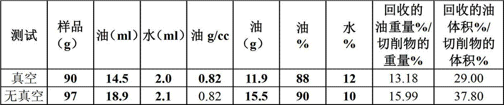
这些结果示出了受到真空3秒的显著效应。具体而言,测试1示出了从经真空处理的切削物中回收油的大约8体积%的改善。These results show a significant effect of exposure to vacuum for 3 seconds. Specifically,
在这项试验中,观察发现在1英寸的筛网上的过量的以及/或者不可变的真空压力和气流速率可引起真空筛网克服筛网振动进而在筛网上拖延切削物,从而阻止了切削物从振荡器上的有效排放。因此,图5所示的真空系统和筛网设计是优选的,其将真空施加在大约7-10英寸上(典型的为筛网长度的大约5-15%),这是因为可实现对真空压力的更大程度的控制。重要的是,为了使切削物穿过筛网时遭受的破坏最小化,真空的位置应使得钻探切削物与筛网之间的钻探浆料缓冲垫在某一时刻为最小,在该时刻切削物与真空接合,而不具有钻探浆料缓冲垫的“干燥的”切削物在显著时间段内不与筛网接合,就不会在该显著时间段内引起对切削物的破坏以及随后生成穿过筛网的细粒。In this test, it was observed that excess and/or constant vacuum pressure and air flow rate on a 1 inch screen caused the vacuum screen to overcome the vibration of the screen and drag the cuttings on the screen, thereby preventing the cuttings. Efficient discharge from the oscillator. Therefore, the vacuum system and screen design shown in Figure 5 is preferred, which applies a vacuum over about 7-10 inches (typically about 5-15% of the screen length) because the vacuum can be achieved Greater control of pressure. Importantly, in order to minimize damage to the cuttings as they pass through the screen, the vacuum is positioned such that the drilling slurry cushion between the drilling cuttings and the screen is minimized at the point at which the cuttings Engaged with vacuum, "dry" cuttings without a drilling slurry cushion do not engage the screen for a significant period of time without causing damage to the cuttings and subsequent generation of through Fines from the sieve.
此外,可利用脉冲式的或常数可变的真空压力流来作为有效地从钻探切削物中去除钻探浆料的方法。此类脉冲的操作频率及/或脉冲压力变化的程度可以被改变以防止在筛网上出现切削物的积累聚结(freezing)同时也使干燥切削物与筛网相接触的时间最小化。In addition, pulsed or constant variable vacuum pressure flow may be utilized as a method of efficiently removing drilling slurry from drilling cuttings. The frequency of operation of such pulses and/or the degree of pulse pressure variation can be varied to prevent freezing accumulation of cuttings on the screen while also minimizing the time that dry cuttings are in contact with the screen.
此外,众所周知,输送到振荡器的钻探浆料经常是泡沫化的,原因是在钻探浆料内溶解的气体在表面膨胀从而引起钻探浆料泡沫化。In addition, it is well known that drilling fluid delivered to a shaker is often foamy due to the expansion of dissolved gases within the drilling fluid at the surface causing the drilling fluid to foam.
过去,这些泡沫化的钻探浆料降低了振荡器的性能,因此根据泡沫化的严重程度,可能需要添加消泡剂来实现使用振荡器的钻探浆料的有效分离。根据本发明,真空的使用不仅使钻探浆料消泡,并且已观察到经受真空处理的泡沫化钻探浆料也将改善钻探浆料/钻探切削物分离,其中泡沫化的钻探浆料可引起保留在切削物上的钻探浆料的值下降1重量%。因此,在一项实施例中,本发明提供了将钻探浆料消泡以作为振荡器/真空过程的产物的有效方法。此外,也可用压缩气体使钻探浆料经受预先泡沫化处理以改善后续的振荡器/真空过程。可通过多种方式来达成预先泡沫化,包括但不限于在浆料通过振荡器之前在浆料流中置放喷头100(其带有气体喷射系统)(图12)。此外,真空操作还提供了脱气能力,在钻探浆料中含有显著量危险气体的情况下,此脱气能力可充当早期警报系统。如下文中所详细解释,在筛网下的一个或多个气体传感器101的使用可在有显著量气体时发送信号,可触发该信号以使用脱气设备。In the past, these foamed drilling slurries have degraded the performance of the vibrator, so depending on the severity of the foaming, the addition of a defoamer may be required to achieve effective separation of the drilling slurries using the vibrator. In accordance with the present invention, the use of vacuum not only defoams the drilling mud, but it has been observed that foamed drilling mud subjected to vacuum treatment will also improve drilling mud/drill cuttings separation, where foamed drilling mud can cause retention The value of the drilling slurry on the cuttings dropped by 1% by weight. Thus, in one embodiment, the present invention provides an efficient method of defoaming drilling slurry as a product of the shaker/vacuum process. In addition, the drilling slurry can also be pre-foamed with compressed gas to improve the subsequent shaker/vacuum process. Pre-foaming can be achieved in a number of ways including, but not limited to, placing a showerhead 100 (with a gas injection system) in the slurry stream prior to the slurry passing through the shaker (Figure 12). In addition, vacuum operation provides a degassing capability that can act as an early warning system in the event that the drilling slurry contains significant quantities of hazardous gases. As explained in detail below, the use of one or
成本分析cost analysis
图7图示了根据本发明的通过使用分离系统而实现的代表性成本效益的分析。如图所示,基于钻孔具体长度及钻孔直径来计算钻探浆料体积及钻探切削物体积。Figure 7 illustrates a representative cost-benefit analysis achieved through use of a separation system in accordance with the present invention. As shown, the drilling slurry volume and drilling cuttings volume are calculated based on the borehole specific length and borehole diameter.
图7图示了在代表性的8天钻探项目中,保留在切削物上的钻探浆料仅有3重量%的改善,但是基于对具有每立方米900美元价值的钻探浆料的回收,可在浆料成本上节省7291美元。Figure 7 illustrates that in a representative 8-day drilling program there was only a 3% improvement in drilling slurry retained on cuttings, but based on the recovery of drilling slurry with a value of $900 per cubic meter, it is possible to Save $7,291 in slurry costs.
如下文所述,由于可达成大于3重量%的改善并且钻探浆料具有可观的更高价值,所以这些数字是保守数字。例如,在另一情形中,如果每天有超过2.4立方米的具有每立方米1650美元浆料价值的钻探浆料从典型装置中被回收,那么成本的节省可为至少每天4000美元。As discussed below, these numbers are conservative since improvements of greater than 3 wt.% can be achieved and the drilling slurry is of considerably higher value. For example, in another scenario, if more than 2.4 cubic meters per day of drilling slurry having a slurry value of $1650 per cubic meter is recovered from a typical installation, the cost savings may be at least $4000 per day.
与现有技术或常规分离系统相比,其中此类现有切削物处理设备需要运进和运出成本以及每天耗费1500-2000美元的租赁费用,作为有效减少钻探项目总成本的方法,常规切削物设备不具有成本效益。但是,根据本发明的系统能够以显著较低的日常成本来部署,并且因此允许操作者在浆料回收上获得净回馈补偿。As an effective way to reduce the overall cost of a drilling project, conventional cutting Physical equipment is not cost-effective. However, systems according to the present invention can be deployed at significantly lower ongoing costs, and thus allow operators to obtain a net return compensation on slurry recovery.
其他现场试验Other Field Trials
进行进一步的现场试验,结果如表3所示。Further field tests were carried out, and the results are shown in Table 3.
表3-具有变化的筛孔尺寸和真空速率的现场试验Table 3 - Field trials with varying mesh sizes and vacuum rates

所列出的数据示出了不同的真空流速率、歧管尺寸、真空表压力、计算所得空气速度以及所测量的保留在切削物上的钻探浆料值的影响。这些运行周期包括84、105、130或145目的筛网网眼尺寸。在每种情况中,真空泵在400立方英尺每分的流动速率下操作,其中例外的是使用非常高的流动速率的运行周期1以及示出在没有施加任何真空的情况下的结果的运行周期4。对每个运行周期以及每个歧管尺寸,对观察到的真空表压力进行记录,其在7英寸汞柱到23英寸汞柱的范围内。如果真空口完全关闭,那么真空泵所能拉动的最大表压是27英寸汞柱。基于歧管尺寸以及真空泵流动速率,确定了计算所得的空气速度。因此,开口歧管面积为0.17平方英尺的运行周期1的计算所得空气速度大约为8400英尺每分。The data presented shows the effect of varying vacuum flow rates, manifold sizes, vacuum gauge pressures, calculated air velocities, and measured values of drilling slurry retained on cuttings. These run cycles included 84, 105, 130 or 145 mesh screen mesh sizes. In each case, the vacuum pump was operated at a flow rate of 400 cubic feet per minute, with the exception of
运行周期1示出了穿过筛网的计算所得的高空气速度的结果。此流动速率导致了筛网上的切削物“聚结”,其随后引起切削物在该区域上堆积。这就需要在操作几分钟之后停止振荡器,以刮掉真空区域的切削物。结果示出高的空气速度在将浆料从切削物移除上是有效的(即7重量%的浆料保留在切削物上),但是从操作的角度来看并不有效因为需要手动清除切削物。
运行周期2和运行周期3示出增加歧管面积的并相应降低空气速度的影响。在这些情况中的每种情况中,系统可操作,因为切削物并未在筛网上聚结并且因此允许连续操作。Run
运行周期4示出在未启用真空的情况下的基线值。在此情况中,保留在切削物上的钻探浆料是19重量%。Run cycle 4 shows the baseline value without vacuum enabled. In this case, the drilling slurry remaining on the cuttings was 19% by weight.
运行周期5-11示出改变筛网网眼尺寸的影响以及对保留在切削物上的钻探浆料的影响。如所示,该等运行周期的每一个都是可操作的并且导致保留在切削物上的钻探浆料的基本上较低的值。重要的是,应注意更为微细的筛网(例如,130目)示出保留在切削物上的钻探浆料低达5.6重量%。Run cycles 5-11 show the effect of changing the mesh size of the screen and the effect on the drilling slurry retained on the cuttings. As shown, each of these operating cycles was operable and resulted in substantially lower values of drilling slurry retained on cuttings. It is important to note that finer screens (eg, 130 mesh) showed as low as 5.6 wt% drilling slurry retained on cuttings.
从操作的角度来看,当保留在切削物上的钻探浆料的值在5-9重量%的范围内时,所回收的切削物具有半干水泥的外表和稠度。From an operational point of view, when the value of drilling slurry retained on the cuttings is in the range of 5-9% by weight, the recovered cuttings have the appearance and consistency of semi-dry cement.
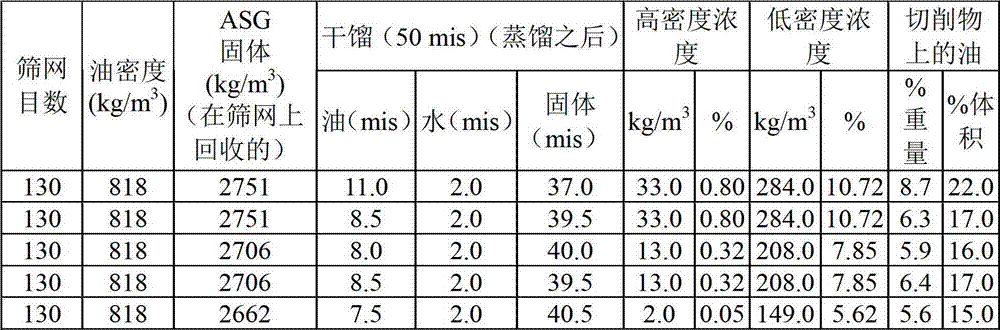
表4示出从130目筛网的表面所回收的多种样品的性质的进一步细节以及在计算保留在切削物上的钻探浆料的值的重量%和体积%时使用的物料平衡。Table 4 shows further details of the properties of various samples recovered from the surface of the 130 mesh screen and the material balance used in calculating the weight % and volume % values of drilling slurry retained on the cuttings.
表4-在130目筛网上回收的样品的代表性值Table 4 - Representative values for samples recovered on a 130 mesh screen
如图8至图11所示,图示了从不同的筛网系统中所回收的钻探浆料之间的比较。图8和图9图示了根据现有技术的使用旋转式真空器件的力度强的筛网分离技术的效应。在旋转式真空器件中,切削物进入被施加高真空压力的旋转筛网管。在管的旋转过程中,随着切削物互相上下翻滚,浆料被脱去进入管的外部。如图8和图9所示,对使用旋转式真空技术的钻探浆料的性质(在给定的深度)进行测量和绘图。根据本发明的实施例如图10和图11所示,对使用筛网真空技术的钻探浆料的相同的特性进行了测量和绘图。如图8和图9所示,塑性粘度(PV)以及10分钟胶凝强度等流变学性质随着时间的推移受到显著的影响,原因是由旋转式真空机器的操作所引起的钻探切削物的物理破碎,在旋转式真空机器处对这些值的显著增长进行了测量。相比之下,如图10和图11所示,本技术的PV和10分钟胶凝强度值保持稳定。使用所示的真空筛网的乳状液稳定性也是比较好的,因为其增大了真空筛网技术的乳状液稳定性。As shown in Figures 8-11, a comparison between drilling slurry recovered from different screen systems is illustrated. Figures 8 and 9 illustrate the effect of aggressive screen separation techniques using rotary vacuum devices according to the prior art. In rotary vacuum devices, cuttings enter a rotating screen tube to which high vacuum pressure is applied. During the rotation of the tube, the slurry is shed into the outside of the tube as the cuttings tumble up and down each other. As shown in Figures 8 and 9, the properties of the drilling slurry (at a given depth) were measured and plotted using the rotary vacuum technique. The same properties were measured and plotted for drilling slurry using screen vacuum technology as shown in Figures 10 and 11 according to an embodiment of the present invention. As shown in Figures 8 and 9, rheological properties such as plastic viscosity (PV) and 10-minute gel strength are significantly affected over time by drilling cuttings caused by the operation of the rotary vacuum machine A significant increase in these values was measured at the rotary vacuum machine for physical crushing. In contrast, as shown in Figures 10 and 11, the PV and 10 minute gel strength values for the present technology remained stable. Emulsion stability using the vacuum screen shown is also better because it increases the emulsion stability of the vacuum screen technique.
因此,本发明的技术解决了过去系统中的关键性问题中的一个,即钻探浆料的强力度分离在钻探浆料的流变学性质上导致了显著不利影响。也就是说,本发明的技术通过实质减少所回收浆料中的微细固体浓度,使得所回收浆料的流变学性质不会受到显著影响,从而保持了流变学性质(具体而言是塑性粘度、10分钟胶凝强度)并且改善了乳状液稳定性。Thus, the technique of the present invention solves one of the critical problems in past systems, namely that the intensive force separation of the drilling slurry results in a significant adverse effect on the rheological properties of the drilling slurry. That is, the technology of the present invention preserves the rheological properties (specifically plasticity) of the recovered slurry by substantially reducing the concentration of fine solids in the recovered slurry such that the rheological properties of the recovered slurry are not significantly affected. viscosity, 10-minute gel strength) and improved emulsion stability.
此外,为了表明细粒产量的减少,对由旋转式真空器件所回收的钻探浆料以及由使用标准离心机的真空筛网器件所回收的钻探浆料进行后处理比较,揭示了与旋转式真空器件相比之下从真空筛网中回收的钻探浆料具有的细粒的百分率(少于10体积%)。Furthermore, to demonstrate the reduction in fines production, a post-treatment comparison of drilling slurry recovered by a rotary vacuum device and that recovered by a vacuum screen device using a standard centrifuge revealed that the difference between rotary vacuum and rotary vacuum The device compared to the drilling slurry recovered from the vacuum screen had a percentage of fines (less than 10% by volume).
此外,根据本发明的真空筛网的使用也通过促进在基于油的钻探浆料内脂肪酸的氧化,可改良井中乳化剂的使用,可对浆料流变学性质具有良好效应。参考图13,图示了对在使用真空筛网以及旋转式真空分离技术的井中初级和次级乳化剂的使用的比较。如图所示,在钻探过程中,真空筛网不需要或只需要将最小量的额外乳化剂添加到所回收的钻探浆料中,而旋转式真空分离的井需要额外的乳化剂。具体而言,在脂肪酸乳化剂可被氧化的情况下,真空筛网的使用可通过提供促进脂肪酸氧化的空气流和钻探浆料的高度混合来协助氧化脂肪酸。例如,不饱和脂肪酸乳化剂的改善氧化的结果可以是在所回收再利用的钻探浆料被重新引入到井中之后的该钻探浆料的改善的乳化性质。也就是说,由于脂肪酸被氧化,氧化作用抵消了切削物的潜在不利影响,从而促成更加稳定的浆料粘度而不需进一步添加乳化剂,并且因此改善了钻探项目的化学维护成本。Furthermore, the use of vacuum screens according to the invention can also improve the use of emulsifiers in wells by promoting the oxidation of fatty acids in oil-based drilling slurries, which can have a favorable effect on the rheological properties of the slurries. Referring to Figure 13, a comparison of the use of primary and secondary emulsifiers in a well using vacuum screen and rotary vacuum separation techniques is illustrated. As shown, vacuum screens require no or minimal addition of additional emulsifiers to the recovered drilling mud during drilling, while rotary vacuum separated wells require additional emulsifiers. Specifically, where fatty acid emulsifiers can be oxidized, the use of vacuum screens can assist in the oxidation of fatty acids by providing an air flow that promotes fatty acid oxidation and high mixing of the drilling slurry. For example, the result of improved oxidation of the unsaturated fatty acid emulsifier may be improved emulsifying properties of the recovered drilling mud after it is reintroduced into the well. That is, as the fatty acids are oxidized, the oxidation counteracts the potentially detrimental effects of cuttings, resulting in a more stable slurry viscosity without the need for further addition of emulsifiers, and thus improving the chemical maintenance cost of the drilling program.
其他设计和操作的考虑Other Design and Operational Considerations
可调节的真空adjustable vacuum
应理解操作者可调节真空压力、筛孔尺寸及/或者真空区域从而在给定的现场情形下优化钻探浆料的分离。It should be understood that the operator can adjust the vacuum pressure, screen size and/or vacuum area to optimize the separation of the drilling slurry for a given field situation.
此外,在其他实施例中,可基于真空歧管相对于筛网下侧的相对面积来调节真空压力及位置。例如,真空歧管可被提供有重叠的板,这些重叠的板允许操作者有效地扩大或缩小歧管的宽度,使得在操作过程中可通过适当的调节系统来改变歧管的开口区域,以使操作者能够优化切削物/浆料分离,具体而言优化切削物暴露在真空压力中的时间。Furthermore, in other embodiments, the vacuum pressure and position may be adjusted based on the relative area of the vacuum manifold with respect to the underside of the screen. For example, vacuum manifolds can be provided with overlapping plates that allow the operator to effectively expand or contract the width of the manifold so that the open area of the manifold can be varied during operation by a suitable adjustment system to Allows the operator to optimize the cuttings/slurry separation, specifically optimizing the time the cuttings are exposed to vacuum pressure.
筛网的清洁Screen cleaning
此系统的另一值得注意的优点是降低了对筛网清洁的需求。如所属领域的技术人员所熟知,由于筛网的堵塞,未改善的振荡器系统需要按期清洁筛网,具体而言是筛网的下游区域。相比之下,由于真空系统的存在,并不需要如此频繁地进行筛网清洁,在基于碳氢化合物的浆料的情况下,这将使执行此项任务的人员所吸入的有害气雾的健康风险最小化。Another noteworthy advantage of this system is the reduced need for screen cleaning. As is well known to those skilled in the art, unimproved shaker systems require periodic cleaning of the screen, specifically the downstream area of the screen, due to clogging of the screen. In contrast, due to the presence of the vacuum system, screen cleaning is not required as frequently, which in the case of hydrocarbon-based slurries would reduce the Health risks are minimized.
筛孔尺寸选择Mesh Size Selection
根本上,对筛孔尺寸的选择主要基于钻探浆料粘度,操作者可以选择较微细的筛网用于低粘度浆料以及选择较粗糙的筛网用于高粘度浆料。然而,操作者通常将会选择对于给定的钻探浆料黏度而言最微细的筛网来提供保留在切削物上的浆料的所需或优化值。Fundamentally, the selection of mesh size is mainly based on the drilling slurry viscosity, and the operator can select a finer screen for low viscosity slurry and a coarser screen for high viscosity slurry. Typically, however, the operator will select the finest screen for a given drilling slurry viscosity to provide the desired or optimal value of slurry retained on the cuttings.
筛网设计screen design
另外,由于振荡器篮并不倾向于都是相同尺寸(即使在特定的振荡器型号中也是如此),可对筛网设计进行多种修改以确保切削物不会在可能存在于设备内的间隙之间见缝掉落。例如,间隙通常可存在于筛网边缘与振荡器篮之间,这样切削物/钻探浆料经过该间隙并且在筛网与真空歧管之间见缝掉落,甚至是在安装有垫圈的情况下也会如此。因此,在各种部署及/或不同型号的振荡器中,可能需要改善的密封系统,例如将唇缘从歧管处抬高到筛网主体以改善密封以及/或者添加垫圈材料到筛网边与篮之间的筛网侧以防止固体落入到较低的托盘区域。Also, since shaker baskets do not tend to all be the same size (even within a particular shaker model), several modifications can be made to the screen design to ensure that cuttings do not get caught in gaps that might exist within the unit There is a seam between them. For example, a gap can often exist between the edge of the screen and the shaker basket so cuttings/drilling slurry can pass through the gap and fall through the gap between the screen and the vacuum manifold, even with gaskets installed The next will be the same. Therefore, in various deployments and/or different shaker models, improved sealing systems may be required, such as raising the lip from the manifold to the screen body to improve sealing and/or adding gasket material to the screen edges Screen sides between baskets to prevent solids from falling into the lower tray area.
气体检测器gas detector
同为优选的是将气体检测器101包括在真空的接收区域中及/或筛网之下以检测在腔室中所堆积的有害气体。可使用气体检测器作为警报系统来作为脱气设备。It is also preferred to include a
原始设备original equipment
上文所描述的实施例强调了将真空系统改装到多种已知振荡器设计的能力。然而,如同所属领域的技术人员所了解的,也可将真空设计并入到新的振荡器设计中。还应理解,优选地在振荡器下游端,将此设计改装到各种现有振荡器设计的能力可能受到空间局限性的限制。然而,上述益处中多者可通过使真空系统位于振荡器的另外一区域来实现(包括振荡器床的中间区域)。The embodiments described above emphasize the ability to retrofit the vacuum system to a variety of known oscillator designs. However, vacuum designs can also be incorporated into new oscillator designs, as is understood by those skilled in the art. It should also be appreciated that the ability to retrofit this design to various existing oscillator designs may be limited by space constraints, preferably at the downstream end of the oscillator. However, many of the above benefits can be achieved by having the vacuum system located in another area of the shaker (including the middle area of the shaker bed).
此外,视振荡器的特定设计而定,可实施在真空歧管与筛网床之间的连接系统中的其他设计。例如,具有张紧筛网的振荡器会使用不同的连接及密封系统来提供到筛网下侧的有效连接。Furthermore, depending on the particular design of the shaker, other designs in the connection system between the vacuum manifold and the screen bed may be implemented. For example, a shaker with a tensioned screen would use a different connection and sealing system to provide an effective connection to the underside of the screen.
安装Install
同为有利的是将真空系统安装在低于振荡器高度的水平以允许所收集的浆料流动并被吸入到真空腔室中。这可确保缓慢移动的岩屑/浆料不大可能被收集在真空系统与介于筛网与真空之间的操作性连接之间的软管系统中。It is also advantageous to mount the vacuum system at a level below the level of the shaker to allow the collected slurry to flow and be drawn into the vacuum chamber. This ensures that slow moving debris/slurry is less likely to be collected in the hose system between the vacuum system and the operative connection between the screen and the vacuum.
加速度计/应变计Accelerometer/Strain Gauge
在另一项实施例中,振荡器具有操作性连接到振荡器上的一个或多个位置的一个或多个加速度计及/或应变计。这些仪表经配置以间接地测量振荡器上的混合的钻探浆料和切削物的相对质量,以提供在振荡器上不同位置的浆料/切削物的质量的定性及/或定量评估。也就是说,通过在某一位置上确定浆料/切削物的质量并且将其与另一不同位置上的浆料/切削物的质量进行比较,可确定钻探浆料/切削物分离的相对程度。该数据可有效用于控制振荡器及/或真空系统的操作。In another embodiment, the oscillator has one or more accelerometers and/or strain gauges operatively connected to one or more locations on the oscillator. These meters are configured to indirectly measure the relative quality of the mixed drilling slurry and cuttings on the shaker to provide qualitative and/or quantitative assessments of the quality of the slurry/cuttings at various locations on the shaker. That is, by determining the mass of slurry/cutting at one location and comparing it to the mass of slurry/cutting at a different location, the relative degree of drilling slurry/cutting separation can be determined . This data can be usefully used to control the operation of the oscillator and/or vacuum system.
复合材料composite material
在另外方面,与当前使用的钢相反,振荡器可由轻量材料构成,诸如复合材料。玻璃纤维、Kevlar纤维以及/或者碳纤维等复合材料的使用可提供振荡器系统(包括筛网框架以及关联振荡部件)的较低的往复运动质量,允许通过最小化振荡器的动量来应用高振动频率并且允许实现对振荡器振幅的更多控制。也就是说,复合设计允许将较高振动频率传递到钻探切削物和浆料上,可引起钻探浆料的粘度的下降,使得在自然条件下其具有典型的触变性。所引起的粘度下降提供浆料与切削物的更大程度的分离。In a further aspect, the oscillator may be constructed of lightweight materials, such as composite materials, as opposed to the currently used steel. The use of composite materials such as glass fiber, Kevlar fiber, and/or carbon fiber provides a low reciprocating mass of the oscillator system (including the screen frame and associated oscillating components), allowing the application of high vibration frequencies by minimizing the momentum of the oscillator And allows more control over the oscillator amplitude. That is, the composite design allows higher vibration frequencies to be transmitted to the drilling cuttings and slurry, which can cause a decrease in the viscosity of the drilling slurry, making it typically thixotropic under natural conditions. The resulting drop in viscosity provides greater separation of the slurry from the cuttings.
另外,复合振荡器应足够轻以允许应变计传感器以及加速度计定位在振荡器篮之下以追踪振荡器上的质量流动,从而允许操作者知晓从井中连续排放的钻探岩屑的相对量。该信息连同已知的钻探速率及孔尺寸一起,可用于调节浆料性质(通常为粘度)以优化在挖掘过程中从井眼中对切削物的移除。Additionally, the compound shaker should be light enough to allow strain gauge sensors as well as accelerometers to be positioned under the shaker basket to track mass flow over the shaker, allowing the operator to know the relative amount of drilling cuttings being continuously discharged from the well. This information, along with known drilling rates and hole sizes, can be used to adjust slurry properties (typically viscosity) to optimize removal of cuttings from the wellbore during excavation.
虽然已参阅优选实施例及其优选用途对本发明进行描述和说明,但本发明并不限于此,因为可对其做出各种修改和变化,而这些修改和变化在本发明的完整、预定的范围内。While the present invention has been described and illustrated with reference to preferred embodiments and preferred uses thereof, the invention is not limited thereto since various modifications and changes may be made thereto which are incorporated in the complete, intended and intended use of the present invention. within range.
Claims (45)
Priority Applications (1)
| Application Number | Priority Date | Filing Date | Title |
|---|---|---|---|
| CN201510830301.1A CN105498339A (en) | 2010-03-18 | 2010-03-31 | Optimization of vacuum system and method for drying drill cuttings |
Applications Claiming Priority (3)
| Application Number | Priority Date | Filing Date | Title |
|---|---|---|---|
| US31535710P | 2010-03-18 | 2010-03-18 | |
| US61/315,357 | 2010-03-18 | ||
| PCT/CA2010/000501 WO2011113132A1 (en) | 2010-03-18 | 2010-03-31 | Optimization of vacuum systems and methods for drying drill cuttings |
Related Child Applications (1)
| Application Number | Title | Priority Date | Filing Date |
|---|---|---|---|
| CN201510830301.1A Division CN105498339A (en) | 2010-03-18 | 2010-03-31 | Optimization of vacuum system and method for drying drill cuttings |
Publications (2)
| Publication Number | Publication Date |
|---|---|
| CN103080461A true CN103080461A (en) | 2013-05-01 |
| CN103080461B CN103080461B (en) | 2016-03-30 |
Family
ID=44648376
Family Applications (2)
| Application Number | Title | Priority Date | Filing Date |
|---|---|---|---|
| CN201510830301.1A Pending CN105498339A (en) | 2010-03-18 | 2010-03-31 | Optimization of vacuum system and method for drying drill cuttings |
| CN201080066711.9A Expired - Fee Related CN103080461B (en) | 2010-03-18 | 2010-03-31 | Optimization of vacuum systems and methods for drying drilling cuttings |
Family Applications Before (1)
| Application Number | Title | Priority Date | Filing Date |
|---|---|---|---|
| CN201510830301.1A Pending CN105498339A (en) | 2010-03-18 | 2010-03-31 | Optimization of vacuum system and method for drying drill cuttings |
Country Status (11)
| Country | Link |
|---|---|
| US (3) | US9015959B2 (en) |
| CN (2) | CN105498339A (en) |
| AU (1) | AU2010348889B2 (en) |
| BR (1) | BR112012023417A2 (en) |
| CA (1) | CA2712774C (en) |
| GB (1) | GB2491073A (en) |
| MX (1) | MX338028B (en) |
| NO (1) | NO20121182A1 (en) |
| NZ (2) | NZ701624A (en) |
| RU (1) | RU2541958C2 (en) |
| WO (1) | WO2011113132A1 (en) |
Cited By (9)
| Publication number | Priority date | Publication date | Assignee | Title |
|---|---|---|---|---|
| CN105032756A (en) * | 2015-09-09 | 2015-11-11 | 徐州天科机械制造有限公司 | Vacuum negative pressure solid-liquid separation vibrating screen |
| CN105080831A (en) * | 2015-09-09 | 2015-11-25 | 徐州天科机械制造有限公司 | Air pressure type solid-liquid separation vibrating screen |
| CN105127093A (en) * | 2015-09-25 | 2015-12-09 | 西南石油大学 | Negative pressure drilling liquid vibration sieve |
| CN110215751A (en) * | 2019-04-12 | 2019-09-10 | 四川宝石机械石油钻头有限责任公司 | Negative pressure solid-liquid separation system applied to roller air exciting |
| CN112588582A (en) * | 2020-11-03 | 2021-04-02 | 东北农业大学 | Composite wave sieve imitating earthworm body surface structure and motion |
| CN112696161A (en) * | 2021-03-24 | 2021-04-23 | 西南石油大学 | Negative pressure generating and gas-liquid separating integrated negative pressure well drilling vibrating screen |
| CN112867903A (en) * | 2018-10-26 | 2021-05-28 | 嘉露酒庄 | Low profile design air channel system and method for providing uniform air flow in a refractive window dryer |
| CN113332789A (en) * | 2021-08-05 | 2021-09-03 | 临沂盛荣环保科技有限公司 | Waste water environmental protection processing apparatus |
| CN119038837A (en) * | 2024-10-30 | 2024-11-29 | 安徽水利开发有限公司 | Slurry separation equipment and method with feeding and exhausting functions |
Families Citing this family (41)
| Publication number | Priority date | Publication date | Assignee | Title |
|---|---|---|---|---|
| US8613360B2 (en) | 2006-09-29 | 2013-12-24 | M-I L.L.C. | Shaker and degasser combination |
| GB2461725B (en) | 2008-07-10 | 2012-06-13 | United Wire Ltd | Improved sifting screen |
| GB2491073A (en) | 2010-03-18 | 2012-11-21 | Daniel Guy Pomerleau | Optimzation of vacuum systems and method for drying drill cuttings |
| CN105064939A (en) * | 2010-05-12 | 2015-11-18 | 波默洛机械公司 | Module extended system and shaker system |
| PL3936574T3 (en) | 2011-06-30 | 2026-01-19 | E. & J. Gallo Winery | Natural crystalline colorant derived from purple carrot |
| GB2505483B (en) * | 2012-08-31 | 2014-11-26 | Cde Global Ltd | Vibrating screen |
| IN2015DN04174A (en) * | 2012-10-23 | 2015-10-16 | Fp Marangoni Inc | |
| US11226155B2 (en) | 2013-03-15 | 2022-01-18 | E. & J. Gallo Winery | Multi-chamber dryer using adjustable conditioned air flow |
| GB2526742A (en) * | 2013-03-30 | 2015-12-02 | Daniel Guy Pomerleau | Improvements in vacuum shaker systems |
| US9610520B2 (en) | 2013-07-29 | 2017-04-04 | Calx Limited | Apparatus and method for treating slurries |
| MX380646B (en) * | 2013-08-16 | 2025-03-12 | Mi Llc | SEPARATOR AND METHOD FOR SEPARATION WITH A PRESSURE DIFFERENTIAL DEVICE. |
| MX2016002215A (en) | 2013-08-27 | 2016-10-07 | Fp Canmechanica Inc | Dual screen assembly for vibrating screening machine. |
| EP3065843A4 (en) | 2013-11-08 | 2017-06-28 | Hugues Wanlin | Rotary vacuum and screen system and methods for separating solids and liquids |
| WO2015081200A1 (en) | 2013-11-26 | 2015-06-04 | M-I L.L.C. | Apparatus, system and method for separating components of a slurry |
| WO2015192245A1 (en) * | 2014-06-20 | 2015-12-23 | Fp Marangoni Inc. | Gravity induced separation of gases and fluids in a vacuum-based drilling fluid recovery system |
| CN104612608A (en) * | 2015-01-30 | 2015-05-13 | 张劲南 | Novel mud solid control system and technology |
| US10081994B2 (en) * | 2015-01-30 | 2018-09-25 | Fp Marangoni Inc. | Screened enclosure with vacuum ports for use in a vacuum-based drilling fluid recovery system |
| CA2910181C (en) * | 2015-05-12 | 2017-04-25 | Cmp Systems, Inc. | Fluid removal system |
| US10399090B2 (en) | 2015-06-12 | 2019-09-03 | M-I L.L.C. | Apparatus for a screen pulse system |
| CA2997176C (en) | 2015-09-01 | 2023-08-08 | Recover Energy Services Inc. | Gas-tight centrifuge for voc separation |
| CA3016380C (en) | 2016-03-03 | 2023-03-21 | Recover Energy Services Inc. | Gas tight horizontal decanter for drilling waste solids washing |
| US11111743B2 (en) | 2016-03-03 | 2021-09-07 | Recover Energy Services Inc. | Gas tight shale shaker for enhanced drilling fluid recovery and drilled solids washing |
| CN106196926A (en) * | 2016-08-23 | 2016-12-07 | 顾腾博 | A kind of square vacuum desiccator |
| US10557665B2 (en) * | 2016-10-14 | 2020-02-11 | Gala Industries, Inc. | Centrifugal pellet dryer |
| CN106595243A (en) * | 2016-12-30 | 2017-04-26 | 天津横天生物科技有限公司 | Traditional Chinese medicine air-curing device |
| US11352539B2 (en) | 2017-05-16 | 2022-06-07 | Recover Energy Services Inc. | Base oil for re-use |
| CN108224998A (en) * | 2018-03-08 | 2018-06-29 | 江苏金陵干燥科技有限公司 | Graphene particles drier special |
| CN108325829A (en) * | 2018-04-24 | 2018-07-27 | 河北冠能石油机械制造有限公司 | Vibrating screen assembly and vibrating screen device |
| US12403483B2 (en) * | 2019-07-16 | 2025-09-02 | Derrick Corporation | Smart solids control system |
| CN110523630A (en) * | 2019-08-06 | 2019-12-03 | 徐州贝峰机械制造有限公司 | A kind of vacuum vibration of engineering machinery easily ships granule dedusting equipment |
| CN113250636B (en) * | 2021-06-26 | 2022-05-24 | 山东交通学院 | A dynamic control system for logging device |
| CN113318538A (en) * | 2021-08-02 | 2021-08-31 | 四川宝石机械专用车有限公司 | Negative pressure vibrating screen gas circuit pulse device |
| CN113550705B (en) * | 2021-09-23 | 2021-12-28 | 西南石油大学 | A pulsed negative pressure drilling vibrating screen |
| CN114700168B (en) * | 2021-09-30 | 2023-07-14 | 中国矿业大学 | A dry-wet combined desliming sorting system and sorting method |
| CN113926708A (en) * | 2021-10-19 | 2022-01-14 | 王绵 | Rotary oscillating sand screening device for road and bridge construction |
| CN113669024B (en) * | 2021-10-22 | 2022-01-04 | 西南石油大学 | An independent double negative pressure drilling vibrating screen |
| CN115504005B (en) * | 2022-09-27 | 2023-09-15 | 安徽淮记食品有限公司 | A full-automatic packing plant for beef soup |
| CN115773632B (en) * | 2022-11-07 | 2024-10-11 | 河南贾湖农业科技有限公司 | A device for making wine waste lees resourceful treatment |
| CN117072119B (en) * | 2023-08-18 | 2024-04-09 | 大庆永铸石油技术开发有限公司 | Device for harmless treatment of drilling cuttings |
| CN117225782A (en) * | 2023-09-07 | 2023-12-15 | 上海神开石油科技有限公司 | Device and method for cleaning and drying rock debris samples |
| CN119237294A (en) * | 2024-12-04 | 2025-01-03 | 河南亿联机械设备有限责任公司 | Vibrating screen with anti-clogging screen plate |
Citations (8)
| Publication number | Priority date | Publication date | Assignee | Title |
|---|---|---|---|---|
| US2161500A (en) * | 1935-01-02 | 1939-06-06 | Jeffrey Mfg Co | Process and apparatus for treatment of mineral materials |
| US6164380A (en) * | 1997-03-17 | 2000-12-26 | Forta Corporation | Method for clearing debris in a bore |
| US20020056667A1 (en) * | 1997-09-02 | 2002-05-16 | Baltzer Terry L. | Vibrating screen assembly with integrated gasket and frame |
| US6892887B2 (en) * | 2003-02-10 | 2005-05-17 | Alpine Mud Products Corp | Polymer drilling bead recovery system and related methods |
| US20060016768A1 (en) * | 2002-04-26 | 2006-01-26 | Grichar Charles N | Shale Shaker |
| US7096942B1 (en) * | 2001-04-24 | 2006-08-29 | Shell Oil Company | In situ thermal processing of a relatively permeable formation while controlling pressure |
| US20070129257A1 (en) * | 2005-12-02 | 2007-06-07 | Clearwater International, Llc | Method for foaming a hydrocarbon drilling fluid and for producing light weight hydrocarbon fluids |
| CN101553322A (en) * | 2006-09-29 | 2009-10-07 | M-I有限公司 | Shaker and degasser combination |
Family Cites Families (49)
| Publication number | Priority date | Publication date | Assignee | Title |
|---|---|---|---|---|
| US2462878A (en) * | 1942-11-23 | 1949-03-01 | Mining Process & Patent Co | Vibrating screen with vacuum control therefor |
| SU99315A1 (en) | 1953-07-11 | 1953-11-30 | Я.Е. Качанов | Pressure Regulator for Vacuum Line |
| US2793996A (en) * | 1955-12-08 | 1957-05-28 | Pan American Petroleum Corp | Oil base drilling fluid |
| SU391868A1 (en) | 1969-01-20 | 1973-07-27 | Dehydrating screener | |
| US3811570A (en) * | 1971-05-20 | 1974-05-21 | Goodyear Tire & Rubber | Polyurethane screen with backing member |
| US3929642A (en) | 1974-03-07 | 1975-12-30 | Linatex Corp Of America | Dewatering system |
| US3970552A (en) | 1974-08-30 | 1976-07-20 | Klockner-Humboldt-Deutz Aktiengesellschaft | Method and means for separation of liquids from a mixture of solids and liquids |
| US4197657A (en) * | 1978-02-21 | 1980-04-15 | Leino Ilkka M | Procedure for drying an organic, most appropriately axylogenic material, such as veneers for instance |
| US4298572A (en) | 1980-02-27 | 1981-11-03 | Energy Detection Company | Mud logging system |
| US4350591A (en) | 1980-10-20 | 1982-09-21 | Lee Joseph E | Drilling mud cleaning apparatus |
| GB2089403A (en) | 1980-12-15 | 1982-06-23 | Milchem Inc | Method and apparatus for washing particulate material |
| US4387514A (en) * | 1981-04-06 | 1983-06-14 | Dresser Industries, Inc. | Method for drying oil well drill cuttings |
| US4397659A (en) | 1981-06-22 | 1983-08-09 | Lucas Industries Limited | Flowline degaser |
| US4492862A (en) | 1981-08-07 | 1985-01-08 | Mathematical Sciences Northwest, Inc. | Method and apparatus for analyzing components of hydrocarbon gases recovered from oil, natural gas and coal drilling operations |
| US4546783A (en) * | 1983-05-02 | 1985-10-15 | Flo Trend Shares, Inc. | Apparatus for washing drill cuttings |
| SU1260505A1 (en) | 1983-07-19 | 1986-09-30 | Всесоюзный научно-исследовательский институт по креплению скважин и буровым растворам | Method of cleaning drilling mud |
| US4639258A (en) | 1983-10-14 | 1987-01-27 | Leon E. Roy | Single pass mud rejuvenation system and method |
| US4635735A (en) | 1984-07-06 | 1987-01-13 | Schlumberger Technology Corporation | Method and apparatus for the continuous analysis of drilling mud |
| US4750920A (en) | 1986-06-30 | 1988-06-14 | Ramteck Systems, Inc. | Single pass mud rejuvenation system and method |
| US4725352A (en) | 1986-12-15 | 1988-02-16 | Haliotis Peter D | Skimmer-vacuum regulator for swimming pool |
| DE3927769C1 (en) * | 1989-08-23 | 1990-11-22 | Werner & Pfleiderer Gmbh, 7000 Stuttgart, De | |
| RU2021038C1 (en) | 1991-04-04 | 1994-10-15 | Рафаил Адамович Маматов | Vibrosieve |
| US5341882A (en) * | 1993-02-10 | 1994-08-30 | Shell Oil Company | Well drilling cuttings disposal |
| US6283302B1 (en) * | 1993-08-12 | 2001-09-04 | Tuboscope I/P, Inc. | Unibody screen structure |
| US5890549A (en) * | 1996-12-23 | 1999-04-06 | Sprehe; Paul Robert | Well drilling system with closed circulation of gas drilling fluid and fire suppression apparatus |
| US5853583A (en) | 1997-03-31 | 1998-12-29 | Kem-Tron Technologies, Inc. | Multi-functional linear motion shaker for processing drilling mud |
| US6170580B1 (en) | 1997-07-17 | 2001-01-09 | Jeffery Reddoch | Method and apparatus for collecting, defluidizing and disposing of oil and gas well drill cuttings |
| US6092390A (en) | 1998-01-02 | 2000-07-25 | Griffith, Jr.; David R. | Portable, automatic, oil recovery system |
| ATE264450T1 (en) * | 1999-02-17 | 2004-04-15 | Q Max Solutions Inc | METHOD AND DEVICE FOR CLEANING DRILLINGS |
| CA2270833C (en) | 1999-04-30 | 2009-11-10 | Kosta Zamfes | Gas trap for drilling mud |
| JP2001060578A (en) * | 1999-08-20 | 2001-03-06 | Nec Corp | Vacuum processing equipment |
| US6607659B2 (en) * | 2000-12-19 | 2003-08-19 | Hutchison-Hayes International, Inc. | Drilling mud reclamation system with mass flow sensors |
| US6679146B2 (en) | 2002-01-11 | 2004-01-20 | International Business Machines Corporation | Die set with disposable molybdenum die plate and improved window plate for universal gang-punch tool |
| US20050082236A1 (en) * | 2002-06-12 | 2005-04-21 | Derrick Corporation | Vibratory screening machine with suction and method for screening a slurry |
| US20060113220A1 (en) * | 2002-11-06 | 2006-06-01 | Eric Scott | Upflow or downflow separator or shaker with piezoelectric or electromagnetic vibrator |
| EP1631367B1 (en) | 2003-06-12 | 2009-08-19 | Axiom Process Limited | Screening apparatus |
| US7337860B2 (en) | 2003-12-01 | 2008-03-04 | Clean Cut Technologies Inc. | Apparatus and process for removing liquids from drill cuttings |
| US20050183994A1 (en) | 2004-02-11 | 2005-08-25 | Hutchison Hayes, L.P. | Integrated Shale Shaker and Dryer |
| WO2006053008A2 (en) * | 2004-11-09 | 2006-05-18 | Schellstede Herman J | High efficiency liquid solid separator |
| US20060254421A1 (en) | 2005-05-12 | 2006-11-16 | Epoch Well Services, Inc. | Gas trap for drilling mud |
| US20070108105A1 (en) * | 2005-11-16 | 2007-05-17 | Burnett George A | Upflow shakers and separators |
| CA2544314C (en) | 2006-04-20 | 2009-06-30 | Willy Rieberer | Drill cutting sampler |
| NO327436B1 (en) * | 2006-04-25 | 2009-06-29 | Cubility As | Fluid treatment system and method of using the same |
| US7909170B2 (en) | 2006-09-29 | 2011-03-22 | M-I L.L.C. | Self-cleaning shaker |
| US20100012556A1 (en) | 2008-07-21 | 2010-01-21 | Pohle Daniel L | Rotating screen material separation system and method |
| BRPI0920770A2 (en) * | 2008-10-29 | 2020-09-01 | Daniel Guy Pomerleau | system and method for drying drill cuttings |
| NO336396B1 (en) * | 2009-10-27 | 2015-08-10 | Optipro As | An improved cell insert filter for a screening machine filter |
| GB2491073A (en) | 2010-03-18 | 2012-11-21 | Daniel Guy Pomerleau | Optimzation of vacuum systems and method for drying drill cuttings |
| CN105064939A (en) | 2010-05-12 | 2015-11-18 | 波默洛机械公司 | Module extended system and shaker system |
-
2010
- 2010-03-31 GB GB1215907.5A patent/GB2491073A/en not_active Withdrawn
- 2010-03-31 CN CN201510830301.1A patent/CN105498339A/en active Pending
- 2010-03-31 CN CN201080066711.9A patent/CN103080461B/en not_active Expired - Fee Related
- 2010-03-31 BR BR112012023417-0A patent/BR112012023417A2/en not_active IP Right Cessation
- 2010-03-31 AU AU2010348889A patent/AU2010348889B2/en not_active Ceased
- 2010-03-31 CA CA2712774A patent/CA2712774C/en not_active Expired - Fee Related
- 2010-03-31 NZ NZ701624A patent/NZ701624A/en not_active IP Right Cessation
- 2010-03-31 NZ NZ602146A patent/NZ602146A/en not_active IP Right Cessation
- 2010-03-31 RU RU2012141944/03A patent/RU2541958C2/en not_active IP Right Cessation
- 2010-03-31 MX MX2012010693A patent/MX338028B/en active IP Right Grant
- 2010-03-31 WO PCT/CA2010/000501 patent/WO2011113132A1/en not_active Ceased
-
2012
- 2012-09-18 US US13/622,216 patent/US9015959B2/en not_active Expired - Fee Related
- 2012-10-15 NO NO20121182A patent/NO20121182A1/en not_active Application Discontinuation
-
2015
- 2015-03-27 US US14/671,768 patent/US20150204151A1/en not_active Abandoned
- 2015-10-07 US US14/877,013 patent/US10335720B2/en not_active Expired - Fee Related
Patent Citations (8)
| Publication number | Priority date | Publication date | Assignee | Title |
|---|---|---|---|---|
| US2161500A (en) * | 1935-01-02 | 1939-06-06 | Jeffrey Mfg Co | Process and apparatus for treatment of mineral materials |
| US6164380A (en) * | 1997-03-17 | 2000-12-26 | Forta Corporation | Method for clearing debris in a bore |
| US20020056667A1 (en) * | 1997-09-02 | 2002-05-16 | Baltzer Terry L. | Vibrating screen assembly with integrated gasket and frame |
| US7096942B1 (en) * | 2001-04-24 | 2006-08-29 | Shell Oil Company | In situ thermal processing of a relatively permeable formation while controlling pressure |
| US20060016768A1 (en) * | 2002-04-26 | 2006-01-26 | Grichar Charles N | Shale Shaker |
| US6892887B2 (en) * | 2003-02-10 | 2005-05-17 | Alpine Mud Products Corp | Polymer drilling bead recovery system and related methods |
| US20070129257A1 (en) * | 2005-12-02 | 2007-06-07 | Clearwater International, Llc | Method for foaming a hydrocarbon drilling fluid and for producing light weight hydrocarbon fluids |
| CN101553322A (en) * | 2006-09-29 | 2009-10-07 | M-I有限公司 | Shaker and degasser combination |
Cited By (11)
| Publication number | Priority date | Publication date | Assignee | Title |
|---|---|---|---|---|
| CN105032756A (en) * | 2015-09-09 | 2015-11-11 | 徐州天科机械制造有限公司 | Vacuum negative pressure solid-liquid separation vibrating screen |
| CN105080831A (en) * | 2015-09-09 | 2015-11-25 | 徐州天科机械制造有限公司 | Air pressure type solid-liquid separation vibrating screen |
| CN105127093A (en) * | 2015-09-25 | 2015-12-09 | 西南石油大学 | Negative pressure drilling liquid vibration sieve |
| CN112867903A (en) * | 2018-10-26 | 2021-05-28 | 嘉露酒庄 | Low profile design air channel system and method for providing uniform air flow in a refractive window dryer |
| CN110215751A (en) * | 2019-04-12 | 2019-09-10 | 四川宝石机械石油钻头有限责任公司 | Negative pressure solid-liquid separation system applied to roller air exciting |
| CN112588582A (en) * | 2020-11-03 | 2021-04-02 | 东北农业大学 | Composite wave sieve imitating earthworm body surface structure and motion |
| CN112588582B (en) * | 2020-11-03 | 2023-05-09 | 东北农业大学 | A composite wave sieve imitating the surface structure and movement of earthworms |
| CN112696161A (en) * | 2021-03-24 | 2021-04-23 | 西南石油大学 | Negative pressure generating and gas-liquid separating integrated negative pressure well drilling vibrating screen |
| CN112696161B (en) * | 2021-03-24 | 2021-06-29 | 西南石油大学 | Negative pressure generating and gas-liquid separating integrated negative pressure well drilling vibrating screen |
| CN113332789A (en) * | 2021-08-05 | 2021-09-03 | 临沂盛荣环保科技有限公司 | Waste water environmental protection processing apparatus |
| CN119038837A (en) * | 2024-10-30 | 2024-11-29 | 安徽水利开发有限公司 | Slurry separation equipment and method with feeding and exhausting functions |
Also Published As
| Publication number | Publication date |
|---|---|
| RU2012141944A (en) | 2014-04-27 |
| CA2712774A1 (en) | 2010-11-12 |
| NZ602146A (en) | 2014-11-28 |
| NZ701624A (en) | 2016-03-31 |
| MX338028B (en) | 2016-03-31 |
| AU2010348889B2 (en) | 2015-07-30 |
| US10335720B2 (en) | 2019-07-02 |
| US20150204151A1 (en) | 2015-07-23 |
| US20160023141A1 (en) | 2016-01-28 |
| CN105498339A (en) | 2016-04-20 |
| GB2491073A (en) | 2012-11-21 |
| CN103080461B (en) | 2016-03-30 |
| MX2012010693A (en) | 2013-02-11 |
| AU2010348889A1 (en) | 2012-09-20 |
| CA2712774C (en) | 2011-09-13 |
| US20130074360A1 (en) | 2013-03-28 |
| BR112012023417A2 (en) | 2018-05-08 |
| WO2011113132A1 (en) | 2011-09-22 |
| GB201215907D0 (en) | 2012-10-24 |
| US9015959B2 (en) | 2015-04-28 |
| RU2541958C2 (en) | 2015-02-20 |
| NO20121182A1 (en) | 2012-10-15 |
Similar Documents
| Publication | Publication Date | Title |
|---|---|---|
| CN103080461B (en) | Optimization of vacuum systems and methods for drying drilling cuttings | |
| CA2741955C (en) | System and method for drying drill cuttings | |
| CN102906367B (en) | Systems and methods for drying drill cuttings | |
| US8201693B2 (en) | Apparatus and method for separating solids from a solids laden liquid | |
| EP3033163B9 (en) | Separator and method of separation with a pressure differential device | |
| US9364777B2 (en) | Apparatus and method for separating solids from a solids laden drilling fluid | |
| US20150096944A1 (en) | Method and system for recovering and processing bulk materials | |
| CA2664173A1 (en) | Shaker and degasser combination | |
| CA2628757A1 (en) | Apparatus and method for separating solids from a solids laden fluid | |
| AU2015249148A1 (en) | Optimization of vacuum systems and methods for drying drill cuttings | |
| AU2015224486A1 (en) | System and method for drying drill cuttings |
Legal Events
| Date | Code | Title | Description |
|---|---|---|---|
| C06 | Publication | ||
| PB01 | Publication | ||
| C10 | Entry into substantive examination | ||
| SE01 | Entry into force of request for substantive examination | ||
| ASS | Succession or assignment of patent right |
Owner name: FP MALANUONI CORP. Effective date: 20140210 |
|
| TA01 | Transfer of patent application right |
Effective date of registration: 20140210 Address after: Calgary, Alberta, Canada River southeast Top Road No. 200 room 280 Mark Wande Processing System Co Ltd (Reference) Applicant after: EHF PI MARANGONI INK Address before: Calgary, Alberta, Canada Eden Road No. 3958, T3A3Z6 Applicant before: Pomerleau Daniel Guy |
|
| TA01 | Transfer of patent application right | ||
| C14 | Grant of patent or utility model | ||
| GR01 | Patent grant | ||
| CF01 | Termination of patent right due to non-payment of annual fee |
Granted publication date: 20160330 Termination date: 20170331 |
|
| CF01 | Termination of patent right due to non-payment of annual fee |