CN103040503A - Stylet handle attachment device - Google Patents
Stylet handle attachment device Download PDFInfo
- Publication number
- CN103040503A CN103040503A CN2012105669145A CN201210566914A CN103040503A CN 103040503 A CN103040503 A CN 103040503A CN 2012105669145 A CN2012105669145 A CN 2012105669145A CN 201210566914 A CN201210566914 A CN 201210566914A CN 103040503 A CN103040503 A CN 103040503A
- Authority
- CN
- China
- Prior art keywords
- stilet
- handle
- contact surface
- bonding part
- sleeve pipe
- Prior art date
- Legal status (The legal status is an assumption and is not a legal conclusion. Google has not performed a legal analysis and makes no representation as to the accuracy of the status listed.)
- Granted
Links
Images


Classifications
-
- A—HUMAN NECESSITIES
- A61—MEDICAL OR VETERINARY SCIENCE; HYGIENE
- A61M—DEVICES FOR INTRODUCING MEDIA INTO, OR ONTO, THE BODY; DEVICES FOR TRANSDUCING BODY MEDIA OR FOR TAKING MEDIA FROM THE BODY; DEVICES FOR PRODUCING OR ENDING SLEEP OR STUPOR
- A61M25/00—Catheters; Hollow probes
- A61M25/01—Introducing, guiding, advancing, emplacing or holding catheters
- A61M25/0102—Insertion or introduction using an inner stiffening member, e.g. stylet or push-rod
-
- A—HUMAN NECESSITIES
- A61—MEDICAL OR VETERINARY SCIENCE; HYGIENE
- A61B—DIAGNOSIS; SURGERY; IDENTIFICATION
- A61B17/00—Surgical instruments, devices or methods
- A61B17/34—Trocars; Puncturing needles
- A61B17/3401—Puncturing needles for the peridural or subarachnoid space or the plexus, e.g. for anaesthesia
-
- A—HUMAN NECESSITIES
- A61—MEDICAL OR VETERINARY SCIENCE; HYGIENE
- A61M—DEVICES FOR INTRODUCING MEDIA INTO, OR ONTO, THE BODY; DEVICES FOR TRANSDUCING BODY MEDIA OR FOR TAKING MEDIA FROM THE BODY; DEVICES FOR PRODUCING OR ENDING SLEEP OR STUPOR
- A61M25/00—Catheters; Hollow probes
- A61M25/0097—Catheters; Hollow probes characterised by the hub
-
- A—HUMAN NECESSITIES
- A61—MEDICAL OR VETERINARY SCIENCE; HYGIENE
- A61M—DEVICES FOR INTRODUCING MEDIA INTO, OR ONTO, THE BODY; DEVICES FOR TRANSDUCING BODY MEDIA OR FOR TAKING MEDIA FROM THE BODY; DEVICES FOR PRODUCING OR ENDING SLEEP OR STUPOR
- A61M25/00—Catheters; Hollow probes
- A61M25/01—Introducing, guiding, advancing, emplacing or holding catheters
- A61M25/0105—Steering means as part of the catheter or advancing means; Markers for positioning
- A61M25/0133—Tip steering devices
- A61M25/0136—Handles therefor
-
- A—HUMAN NECESSITIES
- A61—MEDICAL OR VETERINARY SCIENCE; HYGIENE
- A61M—DEVICES FOR INTRODUCING MEDIA INTO, OR ONTO, THE BODY; DEVICES FOR TRANSDUCING BODY MEDIA OR FOR TAKING MEDIA FROM THE BODY; DEVICES FOR PRODUCING OR ENDING SLEEP OR STUPOR
- A61M25/00—Catheters; Hollow probes
- A61M25/01—Introducing, guiding, advancing, emplacing or holding catheters
- A61M25/06—Body-piercing guide needles or the like
- A61M25/0606—"Over-the-needle" catheter assemblies, e.g. I.V. catheters
-
- A—HUMAN NECESSITIES
- A61—MEDICAL OR VETERINARY SCIENCE; HYGIENE
- A61B—DIAGNOSIS; SURGERY; IDENTIFICATION
- A61B17/00—Surgical instruments, devices or methods
- A61B2017/0042—Surgical instruments, devices or methods with special provisions for gripping
- A61B2017/00455—Orientation indicators, e.g. recess on the handle
-
- A—HUMAN NECESSITIES
- A61—MEDICAL OR VETERINARY SCIENCE; HYGIENE
- A61B—DIAGNOSIS; SURGERY; IDENTIFICATION
- A61B17/00—Surgical instruments, devices or methods
- A61B2017/00477—Coupling
-
- A—HUMAN NECESSITIES
- A61—MEDICAL OR VETERINARY SCIENCE; HYGIENE
- A61M—DEVICES FOR INTRODUCING MEDIA INTO, OR ONTO, THE BODY; DEVICES FOR TRANSDUCING BODY MEDIA OR FOR TAKING MEDIA FROM THE BODY; DEVICES FOR PRODUCING OR ENDING SLEEP OR STUPOR
- A61M25/00—Catheters; Hollow probes
- A61M25/0043—Catheters; Hollow probes characterised by structural features
- A61M2025/0063—Catheters; Hollow probes characterised by structural features having means, e.g. stylets, mandrils, rods or wires to reinforce or adjust temporarily the stiffness, column strength or pushability of catheters which are already inserted into the human body
-
- A—HUMAN NECESSITIES
- A61—MEDICAL OR VETERINARY SCIENCE; HYGIENE
- A61M—DEVICES FOR INTRODUCING MEDIA INTO, OR ONTO, THE BODY; DEVICES FOR TRANSDUCING BODY MEDIA OR FOR TAKING MEDIA FROM THE BODY; DEVICES FOR PRODUCING OR ENDING SLEEP OR STUPOR
- A61M25/00—Catheters; Hollow probes
- A61M25/01—Introducing, guiding, advancing, emplacing or holding catheters
- A61M2025/0175—Introducing, guiding, advancing, emplacing or holding catheters having telescopic features, interengaging nestable members movable in relations to one another
Landscapes
- Health & Medical Sciences (AREA)
- Life Sciences & Earth Sciences (AREA)
- General Health & Medical Sciences (AREA)
- Animal Behavior & Ethology (AREA)
- Veterinary Medicine (AREA)
- Public Health (AREA)
- Engineering & Computer Science (AREA)
- Biomedical Technology (AREA)
- Heart & Thoracic Surgery (AREA)
- Anesthesiology (AREA)
- Biophysics (AREA)
- Pulmonology (AREA)
- Hematology (AREA)
- Surgery (AREA)
- Molecular Biology (AREA)
- Nuclear Medicine, Radiotherapy & Molecular Imaging (AREA)
- Medical Informatics (AREA)
- Pathology (AREA)
- Infusion, Injection, And Reservoir Apparatuses (AREA)
Abstract
A hub assembly, such as for long needles, is disclosed. The hub assembly includes a needle hub having a proximal end and a distal end, having a cannula extending therethrough and protruding from the distal end, with the needle hub having a first engagement portion. The hub assembly also includes a stylet handle having a stylet extending therefrom. The stylet is adapted to be received within a portion of the cannula, with the stylet handle having a second engagement portion. Engagement of the first engagement portion of the needle hub and the second engagement portion of the stylet handle forms a positive lock in which at least a portion of one of the first and second engagement portions is held within the other of the first and second engagement portions in an unbiased state.
Description
The present invention is that international filing date is that November 21, international application no in 2008 are that PCT/US2008/084340, China national application number are 200880122468.0, denomination of invention is divided an application for the application for a patent for invention of " stylet handle attachment device ".
Mutual reference for related application
The application's requirement was submitted on November 21st, 2007, title is the U.S. Provisional Patent Application No.60/989 of " stylet handle attachment device ", 553 priority, and the whole open of this temporary patent application is included in here by reference.
Technical field
The present invention relates to a kind of hub assembly that is used for admitting stilet, and more particularly, relate to a kind of hub assembly that is used for connecting passage silk handle, this stilet handle has corresponding taper match surface.
Background technology
Generally, existing two kinds is used for injectable drug is incorporated into basic fundamental in patient's vertebra zone.The first is incorporated into the spinal anesthesia agent in the epidural space, and " epidural ", and the second is incorporated into the spinal anesthesia agent in the subarachnoid space " vertebra " or " under the arachnoidea " by spinal dural thrusting.Medicine can be any type the liquid undergoing treatment material-it comprises antibiotic, steroid etc., but generally comprise the reagent for anesthesia and pain relieving.
Medicine requires several centimetres the degree of depth of thrusting to the transmission in the subarachnoid space.Be directed to skin and spinal dural puncture and may cause being organized into core (tissue coring), owing to the existence at the lower tissue of arachnoidea, this can lead to complications.In order to prevent from being organized into core, the stilet that typically will form solid elongated member is inserted in the in-core of pin and extends in this core.Having the pin restriction tissue that is inserted in stilet wherein enters in the pin.After inserting a needle in patient body, can from the hole of pin, partially or even wholly take out stilet.
Typically, stilet is attached on the stilet handle, and pin is attached on the pin hub.Stilet handle joint pin hub is to allow optionally to take out stilet from the hole of pin during process.Be used for a kind of mode that the stilet handle is attached on the pin hub is provided: part protrusion, outward extending, on handle; And recessed portion, on the pin hub, be used for admitting projection.Interference engagement is located between projection and the recessed portion, thereby when stilet handle and pin hub joint, thrust is applied on the projection.In this binding design, the assembling force of stilet handle and pin hub and the power of removing are directly related with coefficient of friction and normal force between protrusion and recessed element, and this normal force is associated with interference engagement.And such design typically is being included in 0.001 inch to the 0.005 inch very little interference engagement on the magnitude between the part.Therefore, the very little variation of geometry and frictional force can have tremendous influence for engaging force.In addition, because the assembly of the stilet handle that obtains and pin hub is stored under stress (that is, the engaging) state usually, so engaging force is because creep and temporal evolution.Engaging force this variation meeting in time is so that can not suitably engage between stilet handle and the pin hub.Correspondingly, exist generally the needs for a kind of hub assembly, this hub assembly allows the stilet handle optionally to be connected on the pin hub, thereby consistent engaging force is provided.
Summary of the invention
In one embodiment of the invention, a kind of hub assembly comprises the pin hub, and this pin hub has proximal end and distal end, has the sleeve pipe that passes its extension and give prominence to from distal end.The pin hub also comprises the first bonding part.The hub assembly also comprises the stilet handle, and this stilet handle has the stilet from its extension.Stilet is suitable for being received within the part of sleeve pipe, and the stilet handle has the second bonding part.The joint of the first bonding part of pin hub and the second bonding part of stilet handle forms shape locking (positive lock).
In a kind of structure, the first bonding part is recess, and the second bonding part is projection, and this projection is suitable for being contained in the recess releasedly.Recess can also comprise shoulder, and projection can also comprise the constraint end, and when pin hub and stilet handle formed the shape locking, this constraint end can engage with shoulder.The constraint end of projection can comprise: insert contact surface, and adjacent with the distal end of stilet handle; With remove contact surface, at the nearside that inserts contact surface with to insert contact surface spaced apart.Insert contact surface can from the longitudinal axis of projection along laterally or at least one direction radially extend, and can tilt in the direction from the distal end of constraint end to the proximal end of constraint end.Remove contact surface can from the longitudinal axis of projection along laterally or at least one direction radially extend, and can tilt in the direction from the proximal end of constraint end to the distal end of constraint end.
The recess of hub assembly can also comprise first, and this first is used for transferring to the insertion contact surface that engages projection between the shape lockup period from unlocked position in projection.Recess can also comprise second portion, and this second portion is used for the contact surface of removing of during projection is transferred to unlocked position from shape locking copulational protuberance.In a kind of structure, projection can comprise the first beam and the second beam of opening with the first distance between girders, and the second beam extends substantially abreast along the first beam and with it.In the first beam and the second beam at least one is suitable for from the locking of unlocked position and shape one and transfers in unlocked position and the shape locking another.In another kind structure, during from unlocked position and shape locking one of projection transfers in unlocked position and the shape locking another, the first beam and the towards each other deflection of the second beam.During one from the locking of unlocked position and shape was transferred in unlocked position and the shape locking another, each in the first beam and the second beam can be suitable for about 0.005 inch to about 0.010 inch of deflection.
In the another kind structure, the first beam can comprise: insert contact surface, and adjacent with the distal end of stilet handle; With remove contact surface, at the nearside that inserts contact surface with to insert contact surface spaced apart.The second beam can also comprise: insert contact surface, and adjacent with the distal end of stilet handle; With remove contact surface, at the nearside that inserts contact surface with to insert contact surface spaced apart.Recess can comprise first, and this first is used for transferring between the shape lockup period from unlocked position in projection, engages the insertion contact surface of the first beam and the insertion contact surface of the second beam.Recess can also comprise second portion, and this second portion is used for engaging the contact surface of removing of removing contact surface and the second beam of the first beam during projection is transferred to unlocked position from the shape locking.
The insertion contact surface of the first beam and the insertion contact surface of the second beam can laterally extend from the longitudinal axis of projection, and can tilt in opposite direction to the proximal end that retrains the end in the distal end from the constraint end.The contact surface of removing of removing contact surface and the second beam of the first beam also can laterally extend from the longitudinal axis of projection, and can tilt in opposite direction to the distal end that retrains the end from the proximal end of constraint end.
Pin hub and stilet handle can be suitable in the locking of unlocked position and shape one with unlocked position and shape locking in another between shift, wherein projection all is in the non-deflection orientation in unlocked position and shape lock.During one from the locking of unlocked position and shape was transferred in unlocked position and the shape locking another, projection can be against the part of recess and deflection.
In the another kind structure, the first bonding part is positioned on the first side of sleeve pipe, and the second bonding part is positioned on the first side of stilet, thereby only has the first side when the first side of sleeve pipe and stilet adjacent to each other on time, and pin hub and stilet handle can form the shape locking.The joint of the first bonding part, the second bonding part or throw off at least aly can produce that can hear, appreciable or palpable indication, a kind of in the unlocked position of this indication expression pin hub and stilet handle or the shape locking.The pin hub can also comprise transparent part, in order to the fluid flow of indication by pin.Transparent part can have substantially parabolic curvature.
In another embodiment of the present invention, a kind of needle assembly comprises sleeve pipe, and this sleeve pipe has: distal end is suitable for thrusting in the tissue samples; Proximal end; And vestibule, between distal end and proximal end, extend.Needle assembly also comprises the pin hub, and this pin hub is connected on the proximal end of sleeve pipe, and the pin hub has the first bonding part.Needle assembly also comprises stilet, and this stilet has distal end and proximal end, and stilet is suitable for passing vestibule and is accepted.Needle assembly also comprises the stilet handle, and this stilet handle is connected on the proximal end of stilet, and the stilet handle has the second bonding part.The joint of the first bonding part and the second bonding part is formed on the shape locking between pin hub and the stilet handle, locks desired tearaway load greater than the power that is applied on the stilet thereby discharge shape during the distal end of sleeve pipe is inserted in the tissue samples.
In a kind of structure, the first bonding part is recess, and the second bonding part is projection, and this projection is suitable for being contained in the recess releasedly.Recess can also comprise shoulder, and projection can also comprise the constraint end, and when pin hub and stilet handle formed the shape locking, this constraint end can engage with shoulder.In the another kind structure, projection comprises the first beam and the second beam of opening with the first distance between girders, and the second beam extends substantially abreast along the first beam and with it.Optionally, during from the locking of unlocked position and shape one of projection transfers in unlocked position and the shape locking another, the first beam and the towards each other deflection of the second beam.
The first beam can comprise: insert contact surface, and adjacent with the distal end of stilet handle; With remove contact surface, at the nearside that inserts contact surface with to insert contact surface spaced apart.The second beam can also comprise: insert contact surface, and adjacent with the distal end of stilet handle; With remove contact surface, at the nearside that inserts contact surface with to insert contact surface spaced apart.Recess can comprise first, and this first is used for transferring to the insertion contact surface of joint the first beam between the shape lockup period and the insertion contact surface of the second beam from unlocked position in projection.Recess can also comprise second portion, and this second portion is used for engaging the contact surface of removing of removing contact surface and the second beam of the first beam during projection is transferred to unlocked position from shape locking.
Pin hub and stilet handle can be suitable in the locking of unlocked position and shape one with unlocked position and shape locking in another between shift, projection all is in the non-deflection orientation in unlocked position and shape lock.During one from the locking of unlocked position and shape was transferred in unlocked position and the shape locking another, projection can be against the part of recess and deflection.In another kind structure, the joint of the first bonding part, the second bonding part or throw off in can hear, the appreciable or palpable indication of at least a generation, a kind of in the unlocked position of this indication expression pin hub and stilet handle or the shape locking.Tearaway load can be less than the resistance of sleeve pipe in human tissue sample.In a kind of structure, sleeve pipe is the 18G pin, and tearaway load can be at least greater than 0.25 pound.Tearaway load also can be less than 0.45 pound.In the another kind structure, sleeve pipe is the 22G pin, and tearaway load can be at least greater than 0.09 pound.Tearaway load also can be less than 0.27 pound.In another structure, needle assembly can comprise the pin protector, and this pin protector is circumferentially arranged around the part of pin, and can be arranged at least in part in the part of pin hub.
In yet another embodiment of the present invention, a kind of needle assembly comprises sleeve pipe, and this sleeve pipe has: the oblique angle distal end is suitable for thrusting in the tissue samples; Proximal end; And vestibule, between distal end and proximal end, extend.Needle assembly also comprises the pin hub, and this pin hub is connected on the proximal end of sleeve pipe, and the pin hub has the first bonding part, and this first bonding part comprises the first direction indicator, the oblique angle distal end of this first direction indicator and sleeve pipe directed corresponding.Needle assembly also comprises stilet, and this stilet has an oblique angle distal end and a proximal end, and stilet is suitable for passing vestibule and is accepted.Needle assembly also comprises the stilet handle, this stilet handle is connected on the proximal end of stilet, the stilet handle has the second bonding part, and this second bonding part comprises the second direction indicator, the oblique angle distal end of this second direction indicator and stilet directed corresponding.Only have when first direction indicator and second direction indicator arrange to mate orientation, just allow the first bonding part and the second bonding part to engage.
In a kind of structure, the coupling orientation of first direction indicator and second direction indicator is aimed at the oblique angle distal end of stilet substantially with the oblique angle distal end of sleeve pipe.In the another kind structure, the joint of the first bonding part and the second bonding part forms the shape locking.Optionally, can hear, the appreciable or palpable indication of at least a generation in the disengagement of the formation of shape locking and shape locking, a kind of in the unlocked position of this indication expression pin hub and stilet handle or the shape locking.
When connection with figures is read following detailed description, other details of the present invention and advantage will be more obvious, and the similar portions among the figure is indicated with like reference numerals from start to finish.
Description of drawings
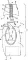
Fig. 1 is the axonometric chart according to the hub assembly of one embodiment of the present of invention.
Fig. 2 is the exploded perspective view of the hub assembly that represents in Fig. 1.
Fig. 3 is the top view of the hub assembly that represents in Fig. 1.
Fig. 4 is the decomposition plan view of the hub assembly that represents in Fig. 1.
Fig. 5 is the feature cutaway top view according to the hub assembly of one embodiment of the present of invention, and this hub assembly is under coupled situation not.
Fig. 6 is the feature front view according to the hub assembly of one embodiment of the present of invention, and this hub assembly never coupled situation is converted to coupled situation.
Fig. 7 is the feature front view according to the hub assembly of one embodiment of the present of invention, and this hub assembly is under coupled situation.
Fig. 8 is the axonometric chart according to the hub assembly of one embodiment of the present of invention, and this hub assembly engages with pin.
Fig. 9 is the exploded perspective view according to the hub assembly of one embodiment of the present of invention, and this hub assembly has pin and the pin protector that engages with it.
Fig. 9 A is the curve diagram that the stilet handle is engaged desired tearaway load and engaging force for the 18G sleeve pipe with the pin hub.
Figure 10 is the front view according to the hub assembly of one embodiment of the present of invention, and this hub assembly has the pin that engages with it under coupled situation.
Figure 11 is the three-dimensional close-up illustration according to the hub assembly of one embodiment of the present of invention, and this hub assembly is under coupled situation not.
Figure 12 is the three-dimensional close-up illustration according to the hub assembly of one embodiment of the present of invention, and this hub assembly is under coupled situation.
Figure 13 is the axonometric chart according to the stilet handle of one embodiment of the present of invention.
Figure 14 is the top view of the stilet handle of Figure 13.
Figure 15 is the front view of the stilet handle of Figure 13.
Figure 16 is the feature sectional side view of the stilet handle of Figure 13 of obtaining of the line 16-16 along Figure 14.
Figure 17 is the side view of the stilet handle of Figure 13 of obtaining of the line 17-17 along Figure 15.
Figure 18 is the close-up cross-sectional view of inner cone of the stilet handle of Figure 13 of obtaining of the Section line 18 along Figure 15.
The specific embodiment
For purpose described below, the dimensional orientation term if you are using, then will be referred to the embodiment of reference, and is directed or otherwise in the following detailed description in the accompanying drawings such as it.Yet, be appreciated that embodiment described below can present plurality of optional and select variation and embodiment.Be appreciated that also concrete device shown in the drawings and that describe only is exemplary here, should do not work as and be restricted.
With reference to Fig. 1-4, hub assembly 1 of the present invention comprises pin hub 4, and this pin hub 4 has proximal end 3 and distal end 9.Pin hub 4 can be suitable for comprising and pass at least in part that its (as from proximal end 3 to distal end 9) extends and from the sleeve pipe 22 of the distal end 9 outstanding segment distances of pin hub 4, as shown in Figure 8.In one embodiment, sleeve pipe 22 can be " minute hand ", as is suitable for being used in those that use in anesthesia, thecal puncture and/or the epidural anesthesia process, has the gauge from 18G to 29G.Yet, also being contemplated to here, hub assembly 1 also can hold with it sleeve pipe 22 of conventional length and specification.As concrete expression among Fig. 9, sleeve pipe 22 is suitable for admitting therein at least in part stilet 26.In one embodiment, stilet 26 is solid slim major axis, and the external diameter that this solid slim major axis has is less than the internal diameter of sleeve pipe 22.In a kind of structure, stilet 26 can have from about 0.007 inch to about 0.013 inch external diameter, this external diameter is less than the internal diameter of the inside of sleeve pipe 22.Stilet 26 can be made by any suitable rigid material, as being made by metal (one or more), metal alloy (one or more) and/or polymer, to strengthen the rigidity of sleeve pipe 22 when being inserted in wherein.Refer again to Fig. 9, stilet 26 can be connected on the stilet handle 10, and at least a portion of this stilet handle 10 is suitable for being held or being gripped by the medical worker.In another embodiment, stilet handle 10 has the stilet 26 from its extension, thereby stilet 26 is suitable for being received within the part of sleeve pipe 22.
With reference to Fig. 1-4, pin hub 4 comprises the first bonding part 6, and stilet handle 10 comprises the second bonding part 16.In one embodiment, it is adjacent with the proximal end 3 of pin hub 4 that the first bonding part 6 is arranged to, and that the second bonding part 16 is arranged to is adjacent with the distal end 11 of stilet handle 10.Pin hub 4 and stilet handle 10 are suitable for engaging matchingly, thereby form shape locking (positive lock) between the first bonding part 6 and the second bonding part 16.Term used herein " shape locking " refers to the joint of at least a portion at least a portion of the second part of the first part, and wherein, the first part remains under the non-bias state in the second part.Refer to wherein not apply the state of quite large thrust such as term used herein " non-bias voltage ".Here be noted that and only have when enough peak value tearaway loads are applied on it, the disengagement of shape locking just can occur, such as will be discussed here.
In one embodiment, the first bonding part 6 of pin hub 4 comprises recess 6A, this recess 6A is limited in the part of housing 4A of pin hub 4, and the second bonding part 16 of stilet handle 10 comprises projection 16A, and this projection 16A is suitable for being contained in releasedly in the recess 6A.In one embodiment, recess 6A is formed by the notch that the housing 4A at pin hub 4 is recessed.In the another kind structure, the housing 4A of shoulder 6B and pin hub 4 integrally forms, and is arranged to adjacent with recess 6A.Projection 16A can comprise that constraint end 16B(is as shown in Figure 2), when the second bonding part 16 of the first bonding part 6 of pin hub 4 and stilet handle 10 formed the shapes locking, this constraint end 16B can engage with shoulder 6B.Although depicting as, the first bonding part 6 of pin hub 4 forms a recess here, and the second bonding part 16 of stilet handle 10 is depicted as here and is comprised projection 16A, but also be contemplated to here, the first bonding part 6 can comprise projection, and the second bonding part 16 can comprise corresponding recess, this corresponding recess is configured to allow admit therein projection, to form the shape locking.Here also be contemplated to, the first bonding part 6 and the second bonding part 16 can be included in any suitable connected structure that forms the shape locking between them.
Refer again to Fig. 1-4, in one embodiment, projection 16A comprises the first beam 12 and substantially extends abreast along the first beam 12 and with it with the first beam 12 isolated the second beam 13, the second beams 13.Each of the first beam 12 and the second beam 13 can have first end 16B, and this first end 16B surmounts the distal end 11 of stilet handle 10 along the longitudinal axes L of stilet handle 10
1Extend, as shown in Figure 4.Each of the first beam 12 and the second beam 13 also has the second end 17, and this second end 17 forms jointly with stilet handle 10, perhaps is attached on it.In this structure, the two all is suitable for the first beam 12 and the second beam 13 being contained in releasedly in the recess 6A simultaneously, to form the shape locking.
Fig. 5-7 is the pin hub 4 shown in as shown in Figure 1 and the joint of stilet handle 10 enlargedly.Specifically, Fig. 5-7 represents that enlargedly the first bonding part 6 and the second bonding part 16 are from the unlocked position that represents, to the inflection point that represents, to the transfer of the shape locking that represents in Fig. 7 in Fig. 6 among Fig. 5.
Generally speaking, before the medical procedure such as epidural or thecal puncture, stilet handle 10 and pin hub 4 under coupled situation, the longitudinal aperture of stilet 26 extend through pin hubs 4 and extending in the sleeve pipe 22.After with needle-penetration skin and spinal dura mater, stilet handle 10 is manually thrown off with pin hub 4, to take out stilet 26 from sleeve pipe 22.Take out sleeve pipe 22 from patient body before, stilet 26 can insert in the sleeve pipe 22 again.
With reference to Fig. 5-7, the first beam 12 of projection 16A and each of the second beam 13 can comprise constraint end 16B.Constraint end 16B can comprise: insert contact surface 14, with the distal end 11 adjacent (as shown in Figure 2) of stilet handle 10; With remove contact surface 15, at the nearside that inserts contact surface 14 with to insert contact surface 14 spaced apart.In a kind of structure, insert contact surface 14 and extend along horizontal direction from the longitudinal axes L (as shown in Figure 5) of projection 16A.Inserting contact surface 14 can be from the distal end 18(of constraint end 16B as shown in Figure 5) to the proximal end 18A(that retrains end 16B also as shown in Figure 5) direction tilt.In one embodiment, insert contact surface 14 and can press about 45 ° of inclinations to its proximal end 18A from the distal end 18 of constraint end 16B.
In another embodiment, removing contact surface 15 extends along horizontal direction from the longitudinal axes L (as shown in Figure 5) of projection 16.Removing contact surface 15 can be from the proximal end 18A(of constraint end 16B as shown in Figure 5) to the distal end 18(that retrains end 16B also as shown in Figure 5) direction tilt.In one embodiment, remove contact surface 15 can from the constraint end 16B proximal end 18A to its distal end 18 by about 45 ° of inclinations.In another embodiment, insert contact surface 14 and remove contact surface 15 and can partly be separated from each other by a cervical region.In another kind structure, insert contact surface 14 and remove contact surface 15 and be limited to the projection 29 that stretches out on each of the first beam 12 and the second beam 13.In another structure, the outward extending projection 29 of the first beam 12 laterally or is radially extended from longitudinal axes L in a kind of orientation, and this orientation is the mirror image from the outward extending projection 29 of the second beam 13.
Refer again to Fig. 5-7, recess 6A comprises shoulder 6B, and this shoulder 6B has first 7, and this first 7 is used for the insertion contact surface 14 of copulational protuberance 16A during the transfer of projection 16A from the unlocked position that represents to the shape locking that represents in Fig. 7 among Fig. 5.The shoulder 6B of recess 6A also comprises second portion 8, and this second portion 8 is during projection 16A transfers to unlocked position from shape locking, and what be used for copulational protuberance 16A removes contact surface 15.The shoulder 6B of recess 6A can also comprise first 7 and second portion 8, and each of this first 7 and second portion 8 and the first beam 12 and the second beam 13 is corresponding.Can select among the embodiment at one, at least one of recess 6A and projection 16A comprises tilt to be inserted contact surface 14 and tilts to remove in the contact surface 15 at least one.In another embodiment, only have one to comprise and tilt to insert contact surface 14 and tilt to remove in the contact surface 15 at least one among recess 6A and the projection 16A.In yet another embodiment, among recess 6A and the projection 16A one comprises tilting to insert contact surface 14 and tilting to remove in the contact surface 15 at least one, and among recess 6A and the projection 16A another comprises passivation or square insertion contact surface 14 and passivation or square at least one of removing in the contact surface 15.
Joint at pin hub 4 and stilet handle 10(as shown in Figure 1) or throw off during, projection 16A is during one from unlocked position and shape locking is transferred in unlocked position and the shape locking another, against the part of recess 6A and deflection.In a kind of structure, at least one of the first beam 12 and the second beam 13 is suitable for transferring to the shape locking that represents from one of unlocked position that represents in Fig. 7 among Fig. 5.In a kind of structure, the first beam 12 and the during transfer toward each other deflection of the second beam 13, as shown in Figure 6.
When stilet handle 10 with respect to pin hub 4 in bonding station not the time, the first bonding part 6 and the second bonding part 16 are in unlocked position, as shown in Figure 5.In unlocked position, the first beam 12 of projection 16A and the second beam 13 are in non-deflection and non-bias voltage orientation.Between the joint aging time of stilet handle 10 and pin hub 4, the first bonding part 6 and the second bonding part 16 contact with each other, as shown in Figure 6.In contact position, projection 16A, such as the first beam 12 and the second beam 13, against a part of deflection of shoulder 6B or recess 6A, and biased.In a kind of structure, the insertion contact surface 14 of projection 16A engages the first 7 of shoulder 6B, and against shoulder 6B bias voltage projection 16A.In another kind structure, the insertion contact surface 14 of the insertion contact surface 14 of the first beam 12 and the second beam 13 engages the first 7 of shoulder 6B, towards longitudinal axes L (as shown in Figure 5) bias voltage the first beam 12 and the second beam 13 the two.Along with stilet handle 10 and pin hub 4 link, as shown in Figure 7, projection 16A is bonded in the recess 6A, and the first bonding part 6 and the second bonding part 16 are in the shape lock-out state.In the shape locking, projection 16A is in non-deflection and non-bias voltage orientation.Specifically, the first beam 12 and the second beam 13 are received in the recess 6A at least in part, and each of the first beam 12 and the second beam 13 is non-bias voltage.
Because it is relatively long that the length of the first beam 12 and the second beam 13 and the first beam 12 are compared with the corresponding width of the second beam 13, the constraint end 16B of the constraint end 16B of the first beam 12 and the second beam 13 can a distance B
ADeflection, this distance B
ASo that little Geometrical change is minimized for the impact of the interfacial force of hub assembly 1.In another kind structure, during a kind of transfer in locking from the unlocked position to the shape of the first beam 12 and the second beam 13, be suitable for to the longitudinal axes L deflection of projection 16A from about 0.005 inch to about 0.010 inch distance B
AHere the distance B that is noted that recess 6A is sized to corresponding with the distance between the first beam 12 and the second beam 13, thereby in determining locking, has the repellence interference engagement between constraint end 16B and shoulder 6B.In a kind of structure, between the second portion 8 of the shoulder 6B that removes contact surface 15 and recess 6A of projection 16A, exist repellence to interfere.In the another kind structure, between the second portion 8 of removing contact surface 15 and shoulder 6B of the first beam 12, exist repellence to interfere, and between the second portion 8 of removing contact surface 15 and shoulder 6B of the second beam 13, exist repellence to interfere.As used herein, term " repellence interference " refers to, when power generally along longitudinal axes L
1When being applied at least one in pin hub 4 and the stilet handle 10 on the direction (as shown in Figure 4), physical contact between the part of the part of the first bonding part 6 and the second bonding part 16 prevents the disengagement of pin hub 4 and stilet handle 10, until apply tearaway load to it.Here only be noted that between stilet handle 10 and pin hub 4 they engage or the action of throwing off during just have " repellence interference ".Although insert contact surface 14 and remove contact surface 15 and depict the relative tilt plane here as, these relative tilt planes form the projection 29 that stretches out, but for inserting contact surface 14 and removing contact surface 15 and can select other shape, such as circular portion, condition is that projection 16A and recess 6A have the repellence interference in the shape locking.In another embodiment, the disengagement of the formation of shape locking and/or shape locking produces can hear, appreciable or palpable indication, and this indication represents respectively shape locking or unlocked position.The demonstration indicator comprise " bang " sound, " click is taken " sound, change color or color shows or forms palpable protuberances or recessed about needle assembly 20.
Throw off in order to make stilet handle 10 and pin hub 4, at the cardinal principle longitudinal direction away from the proximal end 5 of pin hub 4 enough tearaway loads are applied on the stilet handle 10, thereby projection 16A removes contact surface 15, as the first beam 12 and the second beam 13 each remove contact surface 15, engage with the second portion 8 of recess 6A with at first so that projection 16A be in the inflection point, and subsequently so that projection 16A be in the unlocked position.
In one embodiment, remove stilet handle 10 and be attached to stilet 26 needed tearaway loads on it from the pin hub 4 that among Fig. 1, represents, greater than the power on the stilet inclined-plane 26A that during thrusting tissue, is applied to the needle assembly 20 that in Fig. 9, represents.If remove stilet handle 10 needed tearaway loads less than the power that during being inserted into needle assembly 20 tissue, is applied on the stilet inclined-plane 26A that in Fig. 9, represents from pin hub 4, stilet handle 10 may be thrown off prematurely with pin hub 4 so, causes stilet 26 to move towards the position proximad that is positioned at least in part sleeve pipe 22 outsides in sleeve pipe 22.It is to prevent from being organized into during inserting core that stilet 26 is arranged in one of the inside of sleeve pipe 22 or the purpose in the vestibule.If stilet 26 leaves from the inside of sleeve pipe 22 prematurely, tissue may enter the inside of sleeve pipe 22 so, and causes obstruction and/or pollution in the sleeve pipe 22.Under certain situation, the core of organizing that enters the inside of sleeve pipe 22 from skin surface can develop into vertebra endepidermis sample tumor, and these organize core to be deposited in the subarachnoid space of vertebra marrow by sleeve pipe 22.The power that is applied to during inserting on the stilet 26 depends on many factors, and these factors comprise thickness and toughness and the sleeve pipe specification of dermatological specimens.In one embodiment, be from about 0.7 pound to 0.85 pound in scope from the power of thrusting that 18G vertebra pin under 0.1 to 2ips the speed enters application on human skin.For the stilet 26 that represents in Fig. 9, have altogether 30% inclined-plane 26A, the power that is applied on the stilet 26 is about 0.25 pound.Correspondingly, for the 18G sleeve pipe, removing stilet handle 10, make the first bonding part 6 and the second bonding part 16 throw off needed tearaway load thus from pin hub 4, is at least greater than 0.25 pound.In another embodiment, the power of thrusting that enters application on human skin at scope 22G vertebra pin under 0.1 to 2ips the speed is about 0.3 pound.For the stilet 26 that represents in Fig. 9, have altogether 30% inclined-plane 26A, the power that is applied on the stilet 26 is about 0.09 pound.Correspondingly, for the 22G sleeve pipe, removing stilet handle 10, make the first bonding part 6 and the second bonding part 16 throw off needed tearaway load thus from pin hub 4, is at least greater than 0.09 pound.
In another embodiment, in case sleeve pipe 22 has inserted, remove stilet handle 10 and be attached to the tearaway load of stilet 26 needs on it from the pin hub 4 that among Fig. 1, represents, just less than the resistance of taking-up sleeve pipe 22 from patient body (drag force, or be called " drag force ").In case it has as shown in Figure 9 wherein the stilet 26 of being arranged in sleeve pipe 22-, be inserted in patient's the tissue, stilet 26 is just typically taken out from sleeve pipe 22, body fluid is taken a sample and/or by its delivering therapeutic and/or diagnosis fluid by it allowing.In order to prevent from patient body taking out sleeve pipe 22 or sleeve pipe 22 swings in patient body, during stilet handle 10 and 4 disengagements of pin hub, the tearaway load of removing stilet handle 10 needs from pin hub 10 must be less than the drag force of taking out sleeve pipe 22 needs from human tissue sample.The resistance of sleeve pipe 22 in tissue depends on a plurality of factors, and these factors comprise the sleeve pipe specification.In one embodiment, taking out the needed drag force of 18G sleeve pipe from patient body is about 0.45 pound.Correspondingly, for the 18G sleeve pipe, removing stilet handle 10, make the first bonding part 6 and the second bonding part 16 throw off needed tearaway load thus from pin hub 4, is less than 0.45 pound.In another embodiment, for the 18G sleeve pipe, removing stilet handle 10, make the first bonding part 6 and the second bonding part 16 throw off needed tearaway load thus from pin hub 4, is at least greater than 0.25 pound with less than 0.45 pound.In another embodiment, taking out the needed drag force of 22G sleeve pipe from patient body is about 0.27 pound.Correspondingly, for the 22G sleeve pipe, removing stilet handle 10, make the first bonding part 6 and the second bonding part 16 throw off needed tearaway load thus from pin hub 4, is less than 0.27 pound.In another embodiment, for the 22G sleeve pipe, removing stilet handle 10, make the first bonding part 6 and the second bonding part 16 throw off needed tearaway load thus from pin hub 4, is at least greater than 0.09 pound with less than 0.27 pound.
Fig. 9 A is the curve diagram of removing the tearaway load (taking power apart) of stilet handle needs from the pin hub that is attached on the 18G sleeve pipe.Fig. 9 A also illustrates the engaging force (assembling force) that the stilet handle is engaged needs with the pin hub on being attached to the 18G sleeve pipe.As seeing among Fig. 9 A, tearaway load is less than engaging force.Fig. 9 A represents, joint of the present invention and tearaway load the two greater than 0.25 pound with less than 0.5 pound.Correspondingly, the present invention engages to compare with conventional stilet provides improved functional.Although engaging force can be based in part on user preferences and be determined, engaging force should be not too large (as being higher than 0.5 pound power) and cause during the reinserting of the process of sensitivity, causing particularly cannula end 23 of assembly 20() excessive movements or vibration.The engaging force distribution is not only depended on coefficient of friction, the interference between the first bonding part 6 and the second bonding part 16, is reached beam rigidity, and depends on the contact angle between the first 7 that inserts contact surface 14 and recess 6A.In some structure, the rigidity of the first beam 12 and the second beam 13 is scalable also, stilet handle 10 is engaged the amount of needed power with control with pin hub 4.Correspondingly, the present invention compares with conventional hub assembly, the less variation of depending on the frictional force between each part and coefficient of friction.In addition, when stilet handle 10 is connected on the pin hub 4, in projection 16A, as in the first beam 12 and the second beam 13, do not have bias voltage or deflection, thereby elimination is along with the impact of the strain relief of bringing time lapse.
With reference to Fig. 8-9, needle assembly shown in it 20, this needle assembly 20 has: pin hub 4 engages with sleeve pipe 22; With stilet handle 10, engage with stilet 26.As shown in Figure 8, in bonding station, the first bonding part 6 and the second bonding part 16 form the shape locking, and in this shape locking, the second bonding part 16 remains under the non-bias state in the part of the first bonding part 6.In this structure, it is adjacent with the proximal end 5 of pin hub 4 that the first bonding part 6 is arranged to.The distal end 9 of pin hub 4 can comprise cavity 31, and this cavity 31 is sized to corresponding with shape and the physical dimension of pin protector 30 at least in part.In a kind of structure, the size of cavity 31 and size are configured to admit at least in part therein pin protector 30.Pin protector 30 can circumferentially arrange around the part of sleeve pipe 22, and can transfer to the second position from primary importance, in this primary importance, the distal end 23 of sleeve pipe 22 is exposed, in this second position, distal end 23 conductively-closeds of sleeve pipe 22 are to prevent and its accidental contact.
Pin hub 4 can also comprise transparent part 35 hollow, taper, and this transparent part 35 is arranged in the pin hub 4 and is appreciable from the outside of pin hub 4, to discover existing of therein fluid.The open end 36 of transparent part can extend to the nearside of pin hub 4, in order to engaged by the counterpart of stilet handle 10, engages as admitted port 326 by stilet, as shown in figure 13.After in inserting patient body, transparent part 35 can allow to perceive fluid (such as spinal fluid) therein.In one embodiment, transparent part 35 can comprise substantially parabolic curvature, to promote the visuality to the fluid of arranging therein.
Refer again to Fig. 9, the pin hub 4 of needle assembly 20 can also comprise the first bonding part 6, and this first bonding part 6 has first direction indicator 6
Ind, this first direction indicator 6
IndDirected corresponding with the inclined-plane 23A of the distal end 23 of sleeve pipe.Direction indicator 6
IndCan be included in the indication of knowing that maybe can touch of seeing on the part of housing of pin hub 4.Direction indicator 6
IndCan also comprise in the part of the housing that is recessed to pin hub 4 or from the feature of its rise, such as the recess 6A about the ad-hoc location location of the housing of pin hub 4.The stilet handle 10 of needle assembly 20 can also comprise the second bonding part 16, and this second bonding part 16 has second direction indicator 16
Ind, this second direction indicator 16
IndDirected corresponding with the inclined-plane 26A of stilet 26.Direction indicator 16
IndCan also be included in seeing or palpable indication on the part of stilet handle 10.Direction indicator 16
IndCan also comprise in the part that is recessed to stilet handle 10 or from the feature of its rise, such as the projection 16A about the ad-hoc location location of stilet handle 10.Only have when first direction indicator 6
IndWith second direction indicator 16
IndWhen arranging to mate orientation, just allow the joint of the first bonding part 6 and the second bonding part 16.As used herein, term " coupling is directed " refers to that first direction indicator and second direction indicator are aimed at, thereby at least a portion of the first bonding part engages at least a portion of the second bonding part.
The coupling orientation is so that the inclined-plane 26A aligned in general of the inclined-plane 23A of sleeve pipe 22 and stilet 26.In a kind of structure, first direction indicator 6
IndWith second direction indicator 16
IndAt least one a part physically limit the joint of the first bonding part 6 and the second bonding part 16, unless first direction indicator 6
IndWith second direction indicator 16
IndAim at.During stilet 26 reinserting in sleeve pipe 22, the suitable aligning of the inclined-plane 26A of stilet 26 and the inclined-plane 23A of sleeve pipe 22 is crucial, extends the inclined-plane 23A that surmounts sleeve pipe 22 with the inclined-plane 26A that prevents stilet 26.In another embodiment, the first bonding part 6 can be positioned on the first side of sleeve pipe 22, and the second bonding part 16 can be positioned on the first side of stilet 26, thereby only have the first side when the first side of sleeve pipe 22 and stilet 26 adjacent to each other on time, pin hub 4 and stilet handle 10 just form the shape locking.
Can select among the embodiment at one of the present invention, shown in Figure 10-12, provide pin hub 110, this pin hub 110 is suitable for engaging with the non-patient end 112A of the nearside of needle cannula 112.Pin hub 110 comprises the first bonding part 206, and such as notch part 114, this notch part 114 is delimited by first component 116 and second component 118.Each of first component 116 and second component 118 comprises the first 120 adjacent with the unlimited first end 122 of notch part 114.Each of first component 116 and second component 118 also comprises the second portion 124 adjacent with the second end 126 of notch part 114.Stilet handle 130 also is provided, and this stilet handle 130 has the second bonding part 216, such as the first beam 132 and the second beam 134.The first beam 132 and the second beam 134 are fixed in the stilet handle 130 at first end 136 places.Each can also comprise constraint end 140 the first beam 132 and the second beam 134.Constraint end 140 can also comprise: remove contact surface 142, and adjacent with the second end 144; With insertion contact surface 146, be arranged to adjacent with first end 136.
Between the joint aging time of stilet handle 130 and pin hub 110, the first component 116 that the insertion contact surface 146 of the first beam 132 and the second beam 134 can joint pin hub 110 and the first 120 of second component 118.Along with stilet handle 130 advances to pin hub 110, insert contact surface 146 and first's 120 cone contractings, slide (cam) between them, correspondingly to carry out profiling type, and be biased toward one another first component 116 and second component 118.In case the constraint end 140 of the constraint end 140 of the first beam 132 and the second beam 134 just engages against the corresponding second portion 124 of first component 116 and second component 118 under non-bias state by the contact surface 142 of removing of notch part 114, the first beams 132 and the second beam 134.Therefore, in bonding station, stilet handle 130 is not biased or prestrain in pin hub 110.
During the disengagement of stilet handle 130 and pin hub 110, the contact surface 142 of removing of the first beam 132 and the second beam 134 carries out profiling type against the corresponding second portion 124 of first component 116 and second component 118 and slides, to discharge stilet handles 130 from pin hub 110.
With reference to Figure 13-18, a kind of stilet handle 310 of selecting shown in it among another embodiment of the present invention.Shown in Figure 13-18, projection 316 comprises the first beam 318 and the second beam 320, and every beam has constraint end 322.Projection 316 is positioned in the face of housing 324, thereby projection 316 admits a side of port 326 to aim at stilet, and this stilet admits port 326 to be suitable for admitting therein the stilet (not shown).Optionally, stilet handle 310 can comprise coupling ring 328, and the open end 36(that this coupling ring 328 is used for engaging transparent part 35 is as shown in Figure 9), to seal with its formation fluid impermeable.
Although described several embodiments of the present invention in describing in detail hereinbefore, those skilled in the art can make amendment and change for these embodiment, and does not depart from the scope of the present invention and spirit.Correspondingly, it is illustrative and not restrictive more than describing.
Claims (17)
1. needle assembly comprises:
Sleeve pipe has one and be suitable for thrusting distal end in the tissue samples, a proximal end, an and vestibule that extends between described distal end and described proximal end;
The pin hub is connected on the proximal end of described sleeve pipe, and described pin hub has the first bonding part;
Stilet has distal end and proximal end, and described stilet is suitable for passing described vestibule and is accepted;
The stilet handle is connected on the proximal end of described stilet, and described stilet handle has the second bonding part;
Wherein, the joint of described the first bonding part and described the second bonding part is formed on the shape locking between described pin hub and the described stilet handle, locks desired tearaway load greater than the power that is applied to during inserting in the described tissue samples in the distal end of described sleeve pipe on the described stilet thereby discharge described shape.
2. needle assembly according to claim 1, wherein, described the first bonding part is recess, described the second bonding part is projection, and this projection is suitable for being contained in releasedly in the described recess, wherein, described recess also comprises shoulder, described projection also comprises the constraint end, and when described pin hub and the locking of stilet handle formation shape, described constraint end can engage with described shoulder.
3. needle assembly according to claim 2, wherein, described projection comprises the first beam and the second beam of opening with described the first distance between girders, described the second beam extends substantially abreast along described the first beam and with it.
4. needle assembly according to claim 3, wherein, during from unlocked position and shape locking one of described projection transfers in unlocked position and the shape locking another, described the first beam and the towards each other deflection of the second beam.
5. needle assembly according to claim 3, wherein, described the first beam comprises: insert contact surface, adjacent with the distal end of described stilet handle; With remove contact surface, spaced apart at nearside and the described insertion contact surface of described insertion contact surface, and described the second beam comprises: insert contact surface, adjacent with the distal end of described stilet handle; With remove contact surface, spaced apart at nearside and the described insertion contact surface of described insertion contact surface.
6. needle assembly according to claim 5, wherein, described recess comprises: first, be used for transferring between the shape lockup period from unlocked position in described projection, engage the insertion contact surface of described the first beam and the insertion contact surface of described the second beam; And second portion, be used for during described projection is transferred to unlocked position from the shape locking, engaging the contact surface of removing of removing contact surface and described the second beam of described the first beam.
7. needle assembly according to claim 1, wherein, described pin hub and described stilet handle are suitable for shifting between in locking with unlocked position and shape another of in the locking of unlocked position and shape one, and wherein, described projection all is in the non-deflection orientation in described unlocked position and the locking of described shape, and during one from the locking of unlocked position and shape was transferred in unlocked position and the shape locking another, described projection was against the part of described recess and deflection.
8. needle assembly according to claim 1, wherein, the joint of described the first bonding part and described the second bonding part or throw off in can hear, the appreciable or palpable indication of at least a generation, a kind of in the unlocked position of this indication described pin hub of expression and described stilet handle or the shape locking.
9. needle assembly according to claim 1, wherein, described tearaway load is less than the resistance of described sleeve pipe in human tissue sample.
10. needle assembly according to claim 1, wherein, described sleeve pipe is the 18G pin, and described tearaway load is at least greater than 0.25 pound.
11. needle assembly according to claim 1, wherein, described tearaway load is less than 0.45 pound.
12. needle assembly according to claim 1, wherein, described sleeve pipe is the 22G pin, and described tearaway load is at least greater than 0.09 pound.
13. needle assembly according to claim 1, wherein, described tearaway load is less than 0.27 pound.
14. needle assembly according to claim 1 also comprises the pin protector, this pin protector is circumferentially arranged around the part of described sleeve pipe, and can be arranged at least in part in the part of described pin hub.
15. a needle assembly comprises:
Sleeve pipe has one and be suitable for thrusting oblique angle distal end in the tissue samples, a proximal end, an and vestibule that extends between described distal end and described proximal end;
The pin hub is connected on the proximal end of described sleeve pipe, and described pin hub has the first bonding part, and this first bonding part comprises the first direction indicator, the described oblique angle distal end of this first direction indicator and described sleeve pipe directed corresponding;
Stilet has an oblique angle distal end and a proximal end, and described stilet is suitable for passing described vestibule and is accepted;
The stilet handle, be connected on the proximal end of described stilet, described stilet handle has the second bonding part, and this second bonding part comprises the second direction indicator, the described oblique angle distal end of this second direction indicator and described stilet directed corresponding;
Wherein, only have when described first direction indicator and described second direction indicator arrange to mate orientation, just allow described the first bonding part and described the second bonding part to engage and form the shape locking.
16. needle assembly according to claim 15, wherein, the coupling orientation of described first direction indicator and described second direction indicator is aimed at the described oblique angle distal end of described stilet substantially with the described oblique angle distal end of described sleeve pipe.
17. needle assembly according to claim 15, wherein, can hear, the appreciable or palpable indication of at least a generation in the disengagement of the formation of described shape locking and the locking of described shape, a kind of in the unlocked position of this indication described pin hub of expression and described stilet handle or the shape locking.
Applications Claiming Priority (3)
| Application Number | Priority Date | Filing Date | Title |
|---|---|---|---|
| US98955307P | 2007-11-21 | 2007-11-21 | |
| US60/989,553 | 2007-11-21 | ||
| CN2008801224680A CN101909529B (en) | 2007-11-21 | 2008-11-21 | Stylet handle attachment device |
Related Parent Applications (1)
| Application Number | Title | Priority Date | Filing Date |
|---|---|---|---|
| CN2008801224680A Division CN101909529B (en) | 2007-11-21 | 2008-11-21 | Stylet handle attachment device |
Publications (2)
| Publication Number | Publication Date |
|---|---|
| CN103040503A true CN103040503A (en) | 2013-04-17 |
| CN103040503B CN103040503B (en) | 2016-04-27 |
Family
ID=40336483
Family Applications (2)
| Application Number | Title | Priority Date | Filing Date |
|---|---|---|---|
| CN201210566914.5A Active CN103040503B (en) | 2007-11-21 | 2008-11-21 | Stylet handle attachment device |
| CN2008801224680A Active CN101909529B (en) | 2007-11-21 | 2008-11-21 | Stylet handle attachment device |
Family Applications After (1)
| Application Number | Title | Priority Date | Filing Date |
|---|---|---|---|
| CN2008801224680A Active CN101909529B (en) | 2007-11-21 | 2008-11-21 | Stylet handle attachment device |
Country Status (11)
| Country | Link |
|---|---|
| US (1) | US9259553B2 (en) |
| EP (1) | EP2211735B1 (en) |
| JP (1) | JP5115994B2 (en) |
| CN (2) | CN103040503B (en) |
| AU (1) | AU2008326349B2 (en) |
| BR (1) | BRPI0819798B8 (en) |
| CA (1) | CA2706405C (en) |
| ES (1) | ES2485497T3 (en) |
| MX (1) | MX2010005612A (en) |
| NZ (1) | NZ585525A (en) |
| WO (1) | WO2009067661A1 (en) |
Cited By (1)
| Publication number | Priority date | Publication date | Assignee | Title |
|---|---|---|---|---|
| CN111200982A (en) * | 2017-10-10 | 2020-05-26 | 德普伊新特斯产品公司 | Self-retaining spike to insert handle joint |
Families Citing this family (13)
| Publication number | Priority date | Publication date | Assignee | Title |
|---|---|---|---|---|
| BR112012010199B8 (en) * | 2009-11-05 | 2022-08-23 | Nimbus Concepts Llc | NEEDLE FOR INSERTION IN PATIENT |
| EP3750501B1 (en) | 2010-05-21 | 2024-03-06 | Stratus Medical, LLC | Systems for tissue ablation |
| JP5819537B2 (en) * | 2011-10-28 | 2015-11-24 | カスタム メディカル アプリケーションズ インク.Custom Medical Applications, Inc. | Stylet assembly, catheter kit and style assembly including stylet assembly, and related methods |
| EP2977032B1 (en) * | 2013-03-22 | 2018-11-14 | Ad Me Tech Co., Ltd. | Living body heating instrument and controller |
| USD781416S1 (en) | 2014-04-25 | 2017-03-14 | Custom Medical Applications, Inc. | Medical device handle |
| WO2016044600A2 (en) * | 2014-09-18 | 2016-03-24 | Boston Scientific Scimed, Inc. | Helical driven rotating tissue collection |
| ES1143259Y (en) * | 2015-08-21 | 2015-11-25 | Barquero Bartolome Lajarin | NEEDLE TO APPLY NEUROAXIAL ANESTHESIA |
| CN109963610B (en) * | 2016-09-14 | 2021-11-30 | 波士顿科学国际有限公司 | Catheter hub |
| WO2018172817A1 (en) * | 2017-03-23 | 2018-09-27 | Velez Rivera Hector De Jesus | Needle for supplying an anaesthetic with luminous orienting device |
| EP3630257A4 (en) | 2017-05-26 | 2021-03-17 | Piper Access, LLC | Catheter delivery devices, systems, and methods |
| CN117898800A (en) * | 2017-10-12 | 2024-04-19 | 波士顿科学医疗设备有限公司 | Medical device assembly |
| EP4194027A4 (en) * | 2020-09-16 | 2024-01-24 | Eoflow Co., Ltd. | Needle assembly, and liquid medicine injection apparatus comprising same |
| WO2022254964A1 (en) * | 2021-05-31 | 2022-12-08 | 富士フイルム株式会社 | Obturator and trocar |
Citations (5)
| Publication number | Priority date | Publication date | Assignee | Title |
|---|---|---|---|---|
| US4405307A (en) * | 1981-12-10 | 1983-09-20 | Taylor Alan N | Needle assembly and method for fabricating same |
| US4881551A (en) * | 1988-02-01 | 1989-11-21 | Hart Enterprises, Inc. | Soft tissue core biopsy instrument |
| US6056718A (en) * | 1998-03-04 | 2000-05-02 | Minimed Inc. | Medication infusion set |
| EP1661521A1 (en) * | 2004-11-25 | 2006-05-31 | Luigi Carro | Gripping member for biomedical needle |
| CN1951513A (en) * | 2001-02-26 | 2007-04-25 | B.布劳恩梅尔松根公司 | Protective device for an injection needle |
Family Cites Families (16)
| Publication number | Priority date | Publication date | Assignee | Title |
|---|---|---|---|---|
| JPH01146559A (en) * | 1987-12-02 | 1989-06-08 | Nippon Sherwood Kk | Stylet |
| US4952207A (en) * | 1988-07-11 | 1990-08-28 | Critikon, Inc. | I.V. catheter with self-locating needle guard |
| DE3922406C1 (en) | 1989-07-07 | 1990-10-11 | B. Braun Melsungen Ag, 3508 Melsungen, De | |
| US5100390A (en) | 1990-10-22 | 1992-03-31 | Norma A. Lubeck | Lubeck spinal catheter needle |
| US5186712A (en) * | 1991-08-23 | 1993-02-16 | Kansas Creative Devices, Inc. | Intravenous catheter launching device |
| US5250035A (en) | 1992-04-20 | 1993-10-05 | Abbott Laboratories | Cannula and stylet system |
| US5336191A (en) | 1992-08-13 | 1994-08-09 | Dlp, Incorporated | Surgical needle assembly |
| US5425718A (en) * | 1993-10-22 | 1995-06-20 | Tay; Sew-Wah | Self-sticking needle assembly and method for insertion into an artery |
| DE9405166U1 (en) | 1994-03-26 | 1994-05-26 | Krebs, Peter, Dr., 78048 Villingen-Schwenningen | Spinal cannula with transparent handle |
| US5913848A (en) * | 1996-06-06 | 1999-06-22 | Luther Medical Products, Inc. | Hard tip over-the-needle catheter and method of manufacturing the same |
| US5843001A (en) | 1997-09-17 | 1998-12-01 | Goldenberg; Alec | Connector for a replaceable biopsy needle |
| EP1206947A1 (en) * | 2000-06-29 | 2002-05-22 | Ethicon, Inc. | One-piece needle |
| US6595958B1 (en) * | 2000-08-08 | 2003-07-22 | Scimed Life Systems, Inc. | Tortuous path injection device and method |
| US6558353B2 (en) | 2001-01-25 | 2003-05-06 | Walter A. Zohmann | Spinal needle |
| US6656106B2 (en) | 2001-08-17 | 2003-12-02 | Bruno Schmidt | Device for checking seeds in brachytherapy needle |
| US7452354B2 (en) | 2002-06-26 | 2008-11-18 | Inset Technologies Incorporated | Implantable pump connector for catheter attachment |
-
2008
- 2008-11-21 AU AU2008326349A patent/AU2008326349B2/en active Active
- 2008-11-21 CN CN201210566914.5A patent/CN103040503B/en active Active
- 2008-11-21 MX MX2010005612A patent/MX2010005612A/en active IP Right Grant
- 2008-11-21 ES ES08851989.7T patent/ES2485497T3/en active Active
- 2008-11-21 NZ NZ585525A patent/NZ585525A/en not_active IP Right Cessation
- 2008-11-21 JP JP2010535089A patent/JP5115994B2/en active Active
- 2008-11-21 WO PCT/US2008/084340 patent/WO2009067661A1/en not_active Ceased
- 2008-11-21 CA CA2706405A patent/CA2706405C/en active Active
- 2008-11-21 EP EP08851989.7A patent/EP2211735B1/en active Active
- 2008-11-21 BR BRPI0819798A patent/BRPI0819798B8/en active IP Right Grant
- 2008-11-21 CN CN2008801224680A patent/CN101909529B/en active Active
- 2008-11-21 US US12/275,636 patent/US9259553B2/en active Active
Patent Citations (5)
| Publication number | Priority date | Publication date | Assignee | Title |
|---|---|---|---|---|
| US4405307A (en) * | 1981-12-10 | 1983-09-20 | Taylor Alan N | Needle assembly and method for fabricating same |
| US4881551A (en) * | 1988-02-01 | 1989-11-21 | Hart Enterprises, Inc. | Soft tissue core biopsy instrument |
| US6056718A (en) * | 1998-03-04 | 2000-05-02 | Minimed Inc. | Medication infusion set |
| CN1951513A (en) * | 2001-02-26 | 2007-04-25 | B.布劳恩梅尔松根公司 | Protective device for an injection needle |
| EP1661521A1 (en) * | 2004-11-25 | 2006-05-31 | Luigi Carro | Gripping member for biomedical needle |
Cited By (1)
| Publication number | Priority date | Publication date | Assignee | Title |
|---|---|---|---|---|
| CN111200982A (en) * | 2017-10-10 | 2020-05-26 | 德普伊新特斯产品公司 | Self-retaining spike to insert handle joint |
Also Published As
| Publication number | Publication date |
|---|---|
| JP2011504403A (en) | 2011-02-10 |
| JP5115994B2 (en) | 2013-01-09 |
| CA2706405A1 (en) | 2009-05-28 |
| CN101909529B (en) | 2013-12-11 |
| BRPI0819798B8 (en) | 2021-06-22 |
| US9259553B2 (en) | 2016-02-16 |
| BRPI0819798A2 (en) | 2015-05-26 |
| EP2211735A1 (en) | 2010-08-04 |
| WO2009067661A1 (en) | 2009-05-28 |
| CN101909529A (en) | 2010-12-08 |
| CN103040503B (en) | 2016-04-27 |
| BRPI0819798B1 (en) | 2019-09-10 |
| AU2008326349A1 (en) | 2009-05-28 |
| US20090292259A1 (en) | 2009-11-26 |
| NZ585525A (en) | 2013-03-28 |
| CA2706405C (en) | 2013-07-02 |
| ES2485497T3 (en) | 2014-08-13 |
| AU2008326349B2 (en) | 2014-03-27 |
| MX2010005612A (en) | 2010-06-01 |
| EP2211735B1 (en) | 2014-04-30 |
Similar Documents
| Publication | Publication Date | Title |
|---|---|---|
| CN103040503A (en) | Stylet handle attachment device | |
| US5827236A (en) | Injection tool and method of its use | |
| CN100589771C (en) | a trocar plug | |
| CA2552084A1 (en) | Swabbable needle-free injection port valve system with neutral fluid displacement | |
| US4511356A (en) | Cannula, obturator, stylet and needle hub connectors for lumbar disc puncture | |
| EP1051988A2 (en) | Threaded latching mechanism | |
| US5941853A (en) | Needle assemblies | |
| TW200920433A (en) | Disposable injector with manually actuated piston | |
| US11937776B2 (en) | Adapter for a multi-stage console connector | |
| EP4400048B1 (en) | Blood collection tube holder with single needle | |
| EP1707137B1 (en) | Two part obturator assembly | |
| CN213821316U (en) | Bend adjusting pipe and endoscope | |
| US20230301627A1 (en) | Needle guidance device for ultrasound probe | |
| IL105251A (en) | Fluid coupling device and blunt cannula device particularly useful therewith | |
| CA2144450C (en) | Injection tool and method of its use | |
| CN213722341U (en) | A bury device for intramedullary needle | |
| KR20250040304A (en) | Apparatust for liquid material injection | |
| JP7058824B2 (en) | Medical connector | |
| CN210749426U (en) | Positioning device suitable for B ultrasonic guide is with puncture | |
| DE10016443A1 (en) | Coupling arrangement | |
| HK1092675B (en) | Two part obturator assembly | |
| HK1092345B (en) | Angled connection between an obturator tip and an obturator shaft |
Legal Events
| Date | Code | Title | Description |
|---|---|---|---|
| C06 | Publication | ||
| PB01 | Publication | ||
| C10 | Entry into substantive examination | ||
| SE01 | Entry into force of request for substantive examination | ||
| C14 | Grant of patent or utility model | ||
| GR01 | Patent grant |