CN103040413A - Cyclonic separation apparatus - Google Patents
Cyclonic separation apparatus Download PDFInfo
- Publication number
- CN103040413A CN103040413A CN201210388088XA CN201210388088A CN103040413A CN 103040413 A CN103040413 A CN 103040413A CN 201210388088X A CN201210388088X A CN 201210388088XA CN 201210388088 A CN201210388088 A CN 201210388088A CN 103040413 A CN103040413 A CN 103040413A
- Authority
- CN
- China
- Prior art keywords
- cyclonic separation
- fan
- dirt container
- dirt
- cyclone
- Prior art date
- Legal status (The legal status is an assumption and is not a legal conclusion. Google has not performed a legal analysis and makes no representation as to the accuracy of the status listed.)
- Granted
Links
Images


Classifications
-
- A—HUMAN NECESSITIES
- A47—FURNITURE; DOMESTIC ARTICLES OR APPLIANCES; COFFEE MILLS; SPICE MILLS; SUCTION CLEANERS IN GENERAL
- A47L—DOMESTIC WASHING OR CLEANING; SUCTION CLEANERS IN GENERAL
- A47L5/00—Structural features of suction cleaners
- A47L5/12—Structural features of suction cleaners with power-driven air-pumps or air-compressors, e.g. driven by motor vehicle engine vacuum
- A47L5/22—Structural features of suction cleaners with power-driven air-pumps or air-compressors, e.g. driven by motor vehicle engine vacuum with rotary fans
- A47L5/24—Hand-supported suction cleaners
-
- A—HUMAN NECESSITIES
- A47—FURNITURE; DOMESTIC ARTICLES OR APPLIANCES; COFFEE MILLS; SPICE MILLS; SUCTION CLEANERS IN GENERAL
- A47L—DOMESTIC WASHING OR CLEANING; SUCTION CLEANERS IN GENERAL
- A47L9/00—Details or accessories of suction cleaners, e.g. mechanical means for controlling the suction or for effecting pulsating action; Storing devices specially adapted to suction cleaners or parts thereof; Carrying-vehicles specially adapted for suction cleaners
- A47L9/10—Filters; Dust separators; Dust removal; Automatic exchange of filters
- A47L9/16—Arrangement or disposition of cyclones or other devices with centrifugal action
- A47L9/1608—Cyclonic chamber constructions
-
- A—HUMAN NECESSITIES
- A47—FURNITURE; DOMESTIC ARTICLES OR APPLIANCES; COFFEE MILLS; SPICE MILLS; SUCTION CLEANERS IN GENERAL
- A47L—DOMESTIC WASHING OR CLEANING; SUCTION CLEANERS IN GENERAL
- A47L9/00—Details or accessories of suction cleaners, e.g. mechanical means for controlling the suction or for effecting pulsating action; Storing devices specially adapted to suction cleaners or parts thereof; Carrying-vehicles specially adapted for suction cleaners
- A47L9/10—Filters; Dust separators; Dust removal; Automatic exchange of filters
- A47L9/16—Arrangement or disposition of cyclones or other devices with centrifugal action
- A47L9/1616—Multiple arrangement thereof
- A47L9/1625—Multiple arrangement thereof for series flow
- A47L9/1633—Concentric cyclones
-
- A—HUMAN NECESSITIES
- A47—FURNITURE; DOMESTIC ARTICLES OR APPLIANCES; COFFEE MILLS; SPICE MILLS; SUCTION CLEANERS IN GENERAL
- A47L—DOMESTIC WASHING OR CLEANING; SUCTION CLEANERS IN GENERAL
- A47L9/00—Details or accessories of suction cleaners, e.g. mechanical means for controlling the suction or for effecting pulsating action; Storing devices specially adapted to suction cleaners or parts thereof; Carrying-vehicles specially adapted for suction cleaners
- A47L9/10—Filters; Dust separators; Dust removal; Automatic exchange of filters
- A47L9/16—Arrangement or disposition of cyclones or other devices with centrifugal action
- A47L9/1616—Multiple arrangement thereof
- A47L9/1641—Multiple arrangement thereof for parallel flow
-
- A—HUMAN NECESSITIES
- A47—FURNITURE; DOMESTIC ARTICLES OR APPLIANCES; COFFEE MILLS; SPICE MILLS; SUCTION CLEANERS IN GENERAL
- A47L—DOMESTIC WASHING OR CLEANING; SUCTION CLEANERS IN GENERAL
- A47L9/00—Details or accessories of suction cleaners, e.g. mechanical means for controlling the suction or for effecting pulsating action; Storing devices specially adapted to suction cleaners or parts thereof; Carrying-vehicles specially adapted for suction cleaners
- A47L9/10—Filters; Dust separators; Dust removal; Automatic exchange of filters
- A47L9/16—Arrangement or disposition of cyclones or other devices with centrifugal action
- A47L9/165—Construction of inlets
-
- A—HUMAN NECESSITIES
- A47—FURNITURE; DOMESTIC ARTICLES OR APPLIANCES; COFFEE MILLS; SPICE MILLS; SUCTION CLEANERS IN GENERAL
- A47L—DOMESTIC WASHING OR CLEANING; SUCTION CLEANERS IN GENERAL
- A47L9/00—Details or accessories of suction cleaners, e.g. mechanical means for controlling the suction or for effecting pulsating action; Storing devices specially adapted to suction cleaners or parts thereof; Carrying-vehicles specially adapted for suction cleaners
- A47L9/10—Filters; Dust separators; Dust removal; Automatic exchange of filters
- A47L9/16—Arrangement or disposition of cyclones or other devices with centrifugal action
- A47L9/1658—Construction of outlets
- A47L9/1666—Construction of outlets with filtering means
-
- A—HUMAN NECESSITIES
- A47—FURNITURE; DOMESTIC ARTICLES OR APPLIANCES; COFFEE MILLS; SPICE MILLS; SUCTION CLEANERS IN GENERAL
- A47L—DOMESTIC WASHING OR CLEANING; SUCTION CLEANERS IN GENERAL
- A47L9/00—Details or accessories of suction cleaners, e.g. mechanical means for controlling the suction or for effecting pulsating action; Storing devices specially adapted to suction cleaners or parts thereof; Carrying-vehicles specially adapted for suction cleaners
- A47L9/10—Filters; Dust separators; Dust removal; Automatic exchange of filters
- A47L9/16—Arrangement or disposition of cyclones or other devices with centrifugal action
- A47L9/1683—Dust collecting chambers; Dust collecting receptacles
-
- A—HUMAN NECESSITIES
- A47—FURNITURE; DOMESTIC ARTICLES OR APPLIANCES; COFFEE MILLS; SPICE MILLS; SUCTION CLEANERS IN GENERAL
- A47L—DOMESTIC WASHING OR CLEANING; SUCTION CLEANERS IN GENERAL
- A47L9/00—Details or accessories of suction cleaners, e.g. mechanical means for controlling the suction or for effecting pulsating action; Storing devices specially adapted to suction cleaners or parts thereof; Carrying-vehicles specially adapted for suction cleaners
- A47L9/28—Installation of the electric equipment, e.g. adaptation or attachment to the suction cleaner; Controlling suction cleaners by electric means
- A47L9/2868—Arrangements for power supply of vacuum cleaners or the accessories thereof
- A47L9/2884—Details of arrangements of batteries or their installation
-
- Y—GENERAL TAGGING OF NEW TECHNOLOGICAL DEVELOPMENTS; GENERAL TAGGING OF CROSS-SECTIONAL TECHNOLOGIES SPANNING OVER SEVERAL SECTIONS OF THE IPC; TECHNICAL SUBJECTS COVERED BY FORMER USPC CROSS-REFERENCE ART COLLECTIONS [XRACs] AND DIGESTS
- Y10—TECHNICAL SUBJECTS COVERED BY FORMER USPC
- Y10S—TECHNICAL SUBJECTS COVERED BY FORMER USPC CROSS-REFERENCE ART COLLECTIONS [XRACs] AND DIGESTS
- Y10S55/00—Gas separation
- Y10S55/03—Vacuum cleaner
Landscapes
- Engineering & Computer Science (AREA)
- Mechanical Engineering (AREA)
- Filters For Electric Vacuum Cleaners (AREA)
- Cyclones (AREA)
Abstract
本发明公开了一种用于真空清洁器的旋风式分离装置(8、208),该旋风式分离装置包括:第一旋风式分离单元,其包括中空的大致圆筒形污物容器(320、330)和空气入口(326),污物容器具有中心轴线(21、321),空气入口布置成切向地穿过污物容器的一侧;第二旋风式分离单元,其包括具有空气入口(288)、空气出口(256)和排出喷嘴(287)的至少一个旋风分离器;以及大致圆筒形的中间壁(282、290、310),其包围至少一个旋风分离器(284)的空气入口(288),其中,旋风式分离装置包括至少一个突出的唇部(304、328),唇部布置为阻止分离的材料从污物容器的纵向端部返回,并且至少一个唇部(304、328)从污物容器的内表面径向向内突出或者从中间壁径向向外突出。
The present invention discloses a cyclonic separating device (8, 208) for a vacuum cleaner comprising: a first cyclonic separating unit comprising a hollow, generally cylindrical dirt container (320, 330) and an air inlet (326), the dirt container has a central axis (21, 321), the air inlet is arranged to pass tangentially through one side of the dirt container; the second cyclone separation unit, which includes an air inlet ( 288), an air outlet (256) and at least one cyclone of the discharge nozzle (287); and a generally cylindrical intermediate wall (282, 290, 310) surrounding the air inlet of the at least one cyclone (284) (288), wherein the cyclonic separation device comprises at least one protruding lip (304, 328) arranged to prevent separated material from returning from the longitudinal end of the dirt container, and at least one lip (304, 328 ) protrude radially inwards from the inner surface of the dirt container or radially outwards from the intermediate wall.
Description
技术领域 technical field
本发明涉及旋风式分离装置。本发明具体但并非排他地涉及用在真空清洁器中的旋风式分离装置。The present invention relates to cyclonic separation devices. The invention relates particularly, but not exclusively, to cyclonic separation devices for use in vacuum cleaners.
背景技术 Background technique
众所周知,真空清洁器用于收集灰尘和污物,但是也已知能够收集液体的干湿两用的变体真空清洁器。典型地,真空清洁器预期在居住环境中使用,但是它们也可以在诸如工地或花园等其他环境中使用。通常,它们以电力为动力,因而包括:电动机;与电动机的输出轴连接的风扇;用于污浊空气的入口;用于清洁空气的出口;以及用于灰尘、污物(还可能用于液体)的收集腔室。用于电动机的电力可以由市电电源提供,在这种情况下真空清洁器将还包括电源线;由可移除且可更换的电池组提供;或者由一个或多个内置的可充电电池提供,在这种情况下真空清洁器还包括诸如插头或电触点等某些用于将真空清洁器与充电单元连接起来的装置。当从这些电源之一向真空清洁器提供电力时,电动机驱动风扇,从而通过污浊空气入口沿着气流路径经由收集腔室将污浊空气抽吸到清洁空气出口。风扇通常为离心式风扇,尽管其可以为叶轮或者螺旋桨。Vacuum cleaners are well known for collecting dust and dirt, but wet and dry variant vacuum cleaners capable of collecting liquids are also known. Typically vacuum cleaners are intended for use in residential environments, but they may also be used in other environments such as construction sites or gardens. Typically, they are powered by electricity and thus include: an electric motor; a fan connected to the output shaft of the motor; an inlet for dirty air; an outlet for clean air; and for dust, dirt (and possibly liquids) collection chamber. Power for the motor may be provided by mains power, in which case the vacuum cleaner will also include a power cord; by a removable and replaceable battery pack; or by one or more built-in rechargeable batteries , in which case the vacuum cleaner also comprises some means for connecting the vacuum cleaner to the charging unit, such as a plug or electrical contacts. When power is supplied to the vacuum cleaner from one of these power sources, the motor drives the fan, drawing dirty air along the airflow path through the dirty air inlet to the clean air outlet through the collection chamber. The fan is usually a centrifugal fan, although it could be an impeller or propeller.
在沿着气流路径的某些位置还附设有某些用于将污浊空气中所夹带的灰尘和污物(也可能是液体)分离出去并将它们沉积在收集腔室中的装置。该污物分离装置可以包括袋式过滤器、一个或多个过滤器和/或旋风式分离装置。At certain points along the airflow path there are also additional means for separating dust and dirt (and possibly liquids) entrained in the dirty air and depositing them in collection chambers. The dirt separation device may comprise a bag filter, one or more filters and/or a cyclone separation device.
在污物分离装置包括袋式过滤器的情况下,已经由污浊空气入口进入真空清洁器的污浊空气穿过袋式过滤器。这将污浊空气所夹带的灰尘和污物过滤出来并收集在袋式过滤器内。已过滤的物质留在袋式过滤器中,袋式过滤器设置在收集腔室内。然后,清洁空气在风扇的作用下穿过袋式过滤器的另一侧并穿过收集腔室中的格栅。风扇抽入和排出空气,然后,空气从风扇穿出真空清洁器的清洁空气出口。In case the dirt separating device comprises a bag filter, dirty air which has entered the vacuum cleaner through the dirty air inlet passes through the bag filter. This filters out the dust and dirt entrained by the dirty air and collects it in the bag filter. The filtered material remains in the bag filter, which is placed in the collection chamber. The clean air is then driven by the fan through the other side of the bag filter and through the grill in the collection chamber. The fan draws in and exhausts air, which then passes out of the vacuum cleaner's clean air outlet.
袋式过滤器总是存在灰尘和污物穿过袋式过滤器的小风险,并且不期望的是允许灰尘和污物通过风扇并造成损坏。为了减少该潜在的问题,通常设置有跨越收集腔室的格栅的细滤器,以去除在穿过袋式过滤器的气流中所残余的任何细小灰尘和污物颗粒。这是众所周知的前置风扇过滤器。There is always a small risk of dust and dirt passing through the bag filter and it is not desirable to allow dust and dirt to pass through the fan and cause damage. To reduce this potential problem, a fine filter is usually provided across the grid of the collection chamber to remove any fine dust and dirt particles remaining in the airflow through the bag filter. This is known as a pre-fan filter.
偶尔,除了前置风扇过滤器之外,在风扇的下游、气流离开真空清洁器之前设置有高效过滤器。这是为了去除任何残余的极细小颗粒物,其不会损坏风扇或电动机但是可能对家居环境有害。术语“过滤效率”涉及由过滤器去除的颗粒物的相对尺寸。例如,与低效过滤器相比,高效过滤器能够从气流中去除更小的颗粒物。HEPA过滤器是可以去除直径为0.3微米(μm)及更小的极细小颗粒物的高效过滤器。Occasionally, in addition to the pre-fan filter, a HEPA filter is provided downstream of the fan, before the airflow leaves the vacuum cleaner. This is to remove any remaining very fine particles which will not damage the fan or motor but which may be harmful to the domestic environment. The term "filtration efficiency" relates to the relative size of particulate matter removed by a filter. For example, a high-efficiency filter is capable of removing smaller particles from an airflow than a low-efficiency filter. The HEPA filter is a high-efficiency filter that can remove extremely fine particles with a diameter of 0.3 microns (μm) and smaller.
袋式过滤器的用途是过滤夹带在污浊气流中的灰尘和污物并将过滤出的物质收集在袋式过滤器内。这会逐渐地堵塞袋式过滤器。穿过真空清洁器的空气的体积流速逐渐地减小,并且真空清洁器拾取灰尘和污物的能力相应地降低。因此,在袋式过滤器变满之前并在真空清洁器的性能变得不可接受之前,需要更换袋式过滤器。收集腔室的体积必须足够大,以值得袋式过滤器定期更换的成本。The purpose of the bag filter is to filter the dust and dirt entrained in the dirty airflow and collect the filtered material in the bag filter. This gradually clogs the bag filter. The volumetric flow rate of air passing through the vacuum cleaner is progressively reduced, and the ability of the vacuum cleaner to pick up dust and dirt is correspondingly reduced. Therefore, the bag filter needs to be replaced before the bag filter becomes full and before the performance of the vacuum cleaner becomes unacceptable. The volume of the collection chamber must be large enough to justify the cost of periodic bag filter replacement.
立式真空清洁器通常具有立式主体,该立式主体具有污物分离装置、电动机和风扇单元、位于顶部的把手以及位于底部的一对支撑轮。主体上可枢转地安装有清洁器头,清洁器头具有面向地面的污浊空气入口。圆筒式真空清洁器通常具有圆筒形主体,该圆筒形主体具有污物分离装置、电动机和风扇单元以及位于下方的可操纵支撑轮。具有清洁器头的挠性软管与主体连通。袋式过滤器通常用于作为分离装置的立式真空清洁器和圆筒式真空清洁器,这是因为立式真空清洁器和圆筒式真空清洁器的主体具有足够大的收集腔室提供内部空间用于容纳袋式过滤器。Upright vacuum cleaners typically have an upright body with a dirt separator, motor and fan unit, a handle at the top, and a pair of support wheels at the bottom. A cleaner head is pivotally mounted on the body, the cleaner head having a dirty air inlet facing the ground. Cylinder vacuum cleaners typically have a cylindrical body with a dirt separating device, a motor and fan unit and steerable support wheels underneath. A flexible hose with a cleaner head communicates with the main body. Bag filters are commonly used in upright and canister vacuum cleaners as separation units because the bodies of upright and canister vacuum cleaners have collection chambers large enough to provide internal Space is used to accommodate bag filters.
在污物分离装置包括过滤器的情况下,已经由污浊空气入口进入真空清洁器的污浊空气穿过过滤器。这将污浊空气所夹带的灰尘和污物过滤出来并将已过滤的物质留在位于过滤器的上游侧的收集腔室中。有时候,过滤器辅设有海绵,以便吸收污浊气流中所夹带的任何液体。然后,在风扇的作用下,清洁空气穿过过滤器的另一侧,接着,空气从风扇穿过真空清洁器的清洁空气出口。In case the dirt separating device comprises a filter, dirty air which has entered the vacuum cleaner through the dirty air inlet passes through the filter. This filters out dust and dirt entrained by the dirty air and leaves the filtered material in a collection chamber located on the upstream side of the filter. Sometimes the filter is supplemented with a sponge to absorb any liquid entrained in the dirty air stream. The clean air is then passed through the other side of the filter by the fan, and the air is then passed from the fan through the clean air outlet of the vacuum cleaner.
已过滤的物质沉积在过滤器周围并且逐渐地堵塞过滤器。穿过真空清洁器的空气的体积流速逐渐地减小,并且真空清洁器拾取灰尘和污物的能力相应地降低。因此,收集腔室需要定期清空并且过滤器需要经常清洁以减缓该影响。有时,真空清洁器具有过滤器清洁机制。作为选择,过滤器需要被拆卸下来以便例如用刷子进行清洁或者在洗碗机中进行清洁。Filtered material deposits around the filter and gradually clogs the filter. The volumetric flow rate of air passing through the vacuum cleaner is progressively reduced, and the ability of the vacuum cleaner to pick up dust and dirt is correspondingly reduced. Therefore, the collection chamber needs to be emptied regularly and the filter needs to be cleaned frequently to mitigate this effect. Sometimes vacuum cleaners have a filter cleaning mechanism. Alternatively, the filter needs to be disassembled for cleaning eg with a brush or in a dishwasher.
可手持式真空清洁器,如其名字所反映的那样,紧凑、轻便并且用于执行居所周围的少量或快速的清洁任务。典型地,可手持式真空清洁器由电池供电以便于携带。Handheld vacuum cleaners, as their name reflects, are compact, lightweight, and used for light or quick cleaning tasks around the home. Typically, hand-held vacuum cleaners are battery powered for portability.
在与本申请同名的欧洲专利公开EP1752076A中描述了一种具有常规的电动机、风扇和过滤器的结构的可手持式真空清洁器的实例。该真空清洁器具有位于污浊空气通道的一端的污浊空气入口,污浊空气通道通向具有过滤器的收集腔室。收集腔室大致呈圆筒形并且横向地设置在真空清洁器的主体上。污浊空气通道可以与收集腔室一起相对于主体而旋转。当真空清洁器被用户舒适地握持时,可以调节污浊空气通道以接近较窄的空间。An example of a hand-held vacuum cleaner having a conventional motor, fan and filter arrangement is described in European Patent Publication EP1752076A of the same name as the present application. The vacuum cleaner has a dirty air inlet at one end of a dirty air passage leading to a collection chamber with a filter. The collection chamber is generally cylindrical and is disposed transversely on the main body of the vacuum cleaner. The dirty air channel is rotatable with the collection chamber relative to the main body. When the vacuum cleaner is comfortably held by the user, the dirty air passage can be adjusted to access narrower spaces.
在污物分离装置包括旋风式分离装置的情况下,已经由污浊空气入口进入真空清洁器的污浊空气穿过具有一个或多个旋风分离器的旋风式分离装置。旋风分离器是中空的圆筒形腔室、锥形腔室、截锥形腔室或者两个或多个上述种类的腔室的组合。旋风分离器沿其内部的全长或部分长度具有涡流器。涡流器通常为中空的圆筒体,并且具有比旋风分离器的内径小的外径。In case the dirt separating device comprises a cyclonic separating device, dirty air which has entered the vacuum cleaner through the dirty air inlet passes through the cyclonic separating device having one or more cyclones. A cyclone is a hollow cylindrical chamber, a conical chamber, a frusto-conical chamber or a combination of two or more of the foregoing types of chambers. A cyclone separator has swirlers along all or part of its interior length. Vortexers are generally hollow cylinders and have an outer diameter that is smaller than the inner diameter of the cyclone separator.
污浊空气经由切向设置的空气入口进入旋风分离器并且以外旋流的形式围绕旋风分离器而回旋。离心力使灰尘和污物向外移动以撞击旋风分离器单元的侧面并使灰尘单元和污物与气流分离。灰尘和污物沉积在旋风分离器的底部,并且沉积到下方的收集腔室内。然后,已清洁空气的内旋流在旋风分离器中向上回升。涡流器的作用是收集并引导已清洁空气通过位于旋风分离器顶部的空气出口。作为涡流器的可选替代品,旋风分离器可以具有内圆筒形可透气壁,该可透气壁为已清洁空气提供从旋风分离器开始的路径。在风扇的作用下,已清洁空气从旋风分离器穿过真空清洁器的清洁空气出口。Dirty air enters the cyclone separator via tangentially arranged air inlets and swirls around the cyclone separator in the form of an external swirl. Centrifugal force moves the dust and dirt outward to hit the sides of the cyclone unit and separate the dust unit and dirt from the airflow. Dust and dirt settle at the bottom of the cyclone and settle into the collection chamber below. The internal swirling flow of cleaned air then rebounds upwards in the cyclone separator. The function of the vortex collector is to collect and direct the cleaned air through the air outlet located at the top of the cyclone separator. As an optional alternative to a vortexer, a cyclone separator may have an inner cylindrical gas permeable wall that provides a path for cleaned air from the cyclone separator. Cleaned air is passed from the cyclone through the clean air outlet of the vacuum cleaner under the action of a fan.
与具有袋式过滤器的情况类似,具有旋风式分离装置的真空清洁器可以具有前置风扇过滤器以保护风扇和电动机,特别是在气流用于冷却电动机的情况下。然而,随着分离的物质沉积在收集腔室中,流经真空清洁器的空气的体积流速几乎保持恒定。因此,真空清洁器中的旋风式分离装置的吸引人的地方在于拾取灰尘和污物的恒定能力。另一个吸引人的地方在于免除了定期更换袋式过滤器的成本。Similar to the case with bag filters, vacuum cleaners with cyclonic separators can have a pre-fan filter to protect the fan and motor, especially if the airflow is used to cool the motor. However, the volumetric flow rate of air flowing through the vacuum cleaner remains nearly constant as the separated material is deposited in the collection chamber. The attraction of cyclonic separation devices in vacuum cleaners is therefore the constant ability to pick up dust and dirt. Another attraction is the elimination of the cost of periodic bag filter replacements.
在欧洲专利公开EP0042723A中描述了一种具有电动机、风扇和旋风式分离装置的立式真空清洁器的实例。该旋风式分离装置被划分为:第一旋风式分离单元,其具有由环形腔室形成的旋风分离器;以及第二旋风式分离单元,其具有大致截锥形的旋风分离器。第一旋风式分离单元通过通道与第二旋风式分离单元串联。空气依次流经第一旋风式分离单元和第二旋风式分离单元。截锥形旋风分离器的直径小于环形腔室的直径,截锥形旋风分离器部分地嵌设在环形腔室内。已从两个旋风分离单元分离的物质收集在形成于环形腔室的底部的圆筒形收集腔室中。An example of an upright vacuum cleaner with an electric motor, fan and cyclonic separation device is described in European Patent Publication EP0042723A. The cyclonic separation device is divided into a first cyclonic separation unit having a cyclone separator formed by an annular chamber and a second cyclonic separation unit having a substantially frusto-conical cyclone separator. The first cyclonic separation unit is connected in series with the second cyclonic separation unit through the channel. The air flows sequentially through the first cyclonic separation unit and the second cyclonic separation unit. The diameter of the truncated-conical cyclone separator is smaller than that of the annular chamber, and the truncated-conical cyclone separator is partially embedded in the annular chamber. Substances that have been separated from the two cyclone separation units are collected in a cylindrical collection chamber formed at the bottom of the annular chamber.
术语“分离效率”以与过滤效率相同的方式使用,并且“分离效率”涉及旋风式分离装置去除小颗粒物的相对能力。例如,与低效旋风分离单元相比,高效旋风分离单元能够从气流中去除更小的颗粒物。影响分离效率的因素可以包括旋风分离器的污浊空气入口的尺寸和倾角、旋风分离器的清洁空气出口的尺寸、旋风分离器的任何截锥形部分的锥角以及旋风分离器的直径和长度。The term "separation efficiency" is used in the same manner as filtration efficiency, and "separation efficiency" relates to the relative ability of a cyclonic separation device to remove small particulate matter. For example, a high-efficiency cyclone unit is capable of removing smaller particles from an airflow than a low-efficiency cyclone unit. Factors affecting separation efficiency may include the size and inclination of the dirty air inlet of the cyclone, the size of the clean air outlet of the cyclone, the cone angle of any frusto-conical portion of the cyclone, and the diameter and length of the cyclone.
小直径的旋风分离器通常具有比大直径的旋风分离器更高的分离效率,尽管上面所列举的其他因素可能具有同等重要的影响。Smaller diameter cyclones generally have higher separation efficiencies than larger diameter cyclones, although the other factors enumerated above may have an equally important influence.
EP0042723A的第一旋风式分离单元具有比第二旋风式分离单元低的分离效率。第一旋风式分离单元从气流中分离较大的灰尘和污物。这使得第二旋风式分离单元在其最佳工况下作用于相对清洁的气流,并将较小的灰尘和污物分离出。The first cyclonic separation unit of EP0042723A has a lower separation efficiency than the second cyclonic separation unit. The first cyclonic separation unit separates larger dust and dirt from the air stream. This allows the second cyclonic separation unit to operate at its optimum on a relatively clean airflow and separate out smaller dust and dirt.
在英国专利公开No.GB2440110A中描述了一种具有电动机、风扇和旋风式分离装置的可手持式真空清洁器。该旋风式分离装置比EP0042723A中的旋风式分离装置小,以便于应用在可手持式真空机中。该旋风分离器被划分为第一旋风式分离单元和位于第一旋风式分离单元的下游的第二旋风式分离单元。第一旋风式分离单元的分离效率低于第二旋风式分离单元的分离效率。In British Patent Publication No. GB2440110A a hand-held vacuum cleaner with electric motor, fan and cyclonic separation device is described. The cyclone separation device is smaller than the cyclone separation device in EP0042723A, so that it can be applied in a hand-held vacuum machine. The cyclone separator is divided into a first cyclonic separation unit and a second cyclonic separation unit located downstream of the first cyclonic separation unit. The separation efficiency of the first cyclonic separation unit is lower than the separation efficiency of the second cyclonic separation unit.
发明内容 Contents of the invention
本发明的目的是提供一种具有改进的污物分离能力的用于真空清洁器的旋风式分离装置。本发明的另一个目的是提供一种包括这种旋风式分离装置的电动机和风扇结构。本发明的另一个目的是提供一种包括这种电动机、风扇和旋风式分离装置的结构的真空清洁器。It is an object of the present invention to provide a cyclonic separation device for a vacuum cleaner with improved dirt separation capacity. Another object of the present invention is to provide a motor and fan structure including such a cyclone separation device. Another object of the present invention is to provide a vacuum cleaner comprising such a structure of a motor, a fan and a cyclone type separating device.
因此,在第一方面中,本发明提供一种用于真空清洁器的旋风式分离装置,所述旋风式分离装置包括:第一旋风式分离单元,其包括中空的大致圆筒形污物容器和空气入口,所述污物容器具有纵向中心轴线,所述空气入口布置成切向地穿过所述污物容器的一侧;第二旋风式分离单元,其包括具有空气入口、空气出口和排出喷嘴的至少一个旋风分离器;以及大致圆筒形的中间壁,其布置在所述污物容器内,其中所述中间壁包围所述至少一个旋风分离器的空气入口,其中,所述第二旋风式分离单元位于所述污物容器内,所述第二旋风式分离单元在所述第一旋风式分离单元的下游接收气流,所述第一旋风式分离单元和所述第二旋风式分离单元布置为将从气流中分离出来的材料沉积在所述污物容器的纵向端部,所述旋风式分离装置包括至少一个突出的唇部所述唇部布置为阻止分离的材料从所述污物容器的纵向端部返回,并且所述至少一个唇部从所述污物容器的内表面径向向内突出或者从所述中间壁径向向外突出。这是两段式旋风分离装置,具有改进的旋风分离能力和比单段式旋风分离装置更高的分离效率。所述中间壁将所述或各个旋风分离器的入口与污物容器中的污浊气流隔开。所述第一旋风式分离单元中的突出的唇部允许已经分离的材料在到达污物容器的底部,并且可以在该材料可能再次夹带在流向旋风分离器的空气流中之前将其反向捕获。如此,突出的唇部有助于旋风分离作用。Accordingly, in a first aspect, the present invention provides a cyclonic separating device for a vacuum cleaner, said cyclonic separating device comprising: a first cyclonic separating unit comprising a hollow substantially cylindrical dirt container and an air inlet, the dirt container has a longitudinal center axis, the air inlet is arranged tangentially through one side of the dirt container; a second cyclonic separation unit comprising an air inlet, an air outlet and at least one cyclone separator of the discharge nozzle; and a substantially cylindrical intermediate wall arranged in the dirt container, wherein the intermediate wall surrounds the air inlet of the at least one cyclone separator, wherein the first Two cyclonic separation units are located within the dirt container, the second cyclonic separation unit receiving the air flow downstream of the first cyclonic separation unit, the first cyclonic separation unit and the second cyclonic separation unit The separation unit is arranged to deposit separated material from the air flow at a longitudinal end of the dirt container, the cyclonic separation device comprising at least one protruding lip arranged to prevent separated material from flowing from the The longitudinal end of the dirt container returns and the at least one lip protrudes radially inwardly from the inner surface of the dirt container or radially outwardly from the intermediate wall. This is a two-stage cyclone separation unit with improved cyclone separation capacity and higher separation efficiency than single-stage cyclone separation units. The intermediate wall separates the inlet of the or each cyclone separator from the dirty air flow in the dirt container. A protruding lip in the first cyclonic separation unit allows material that has been separated to reach the bottom of the dirt container and can be reverse captured before it can become entrained again in the air flow to the cyclone . As such, the protruding lip facilitates the cyclonic separation action.
所述唇部可以是穿孔的、间断的或环形的。优选地,所述至少一个突出的唇部是环形的。所述至少一个唇部围绕所述第一旋风式分离单元一直延伸以均匀地围绕所述污物容器扩大其效果。The lip may be perforated, interrupted or annular. Preferably, said at least one protruding lip is annular. Said at least one lip extends all the way around said first cyclonic separation unit to amplify its effect uniformly around said dirt container.
优选地,所述至少一个唇部包括从所述污物容器内表面径向向内突出的唇部和从所述中间壁径向向外突出的唇部。所述唇部可以在第一旋风式分离单元的内环形侧和外环形侧两者处捕获分离的材料,并且可以在之间捕获较大的污物,例如绒毛球或动物毛发。Preferably, said at least one lip comprises a lip projecting radially inwardly from said dirt container inner surface and a lip projecting radially outwardly from said intermediate wall. The lip can capture separated material at both the inner and outer annular sides of the first cyclonic separation unit, and can capture larger dirt such as fluff balls or animal hair in between.
优选地,所述污物容器上的唇部和所述中间壁上的唇部以所述污物容器的纵向长度的至少5%轴向偏置。这形成第一旋风式分离单元内的大致环形空间中的扭曲,这扰乱层流式气流并且有助于避免分离的材料从污物容器的底部逃逸。Preferably, the lip on the dirt container and the lip on the intermediate wall are axially offset by at least 5% of the longitudinal length of the dirt container. This creates a twist in the generally annular space within the first cyclonic separation unit, which disrupts the laminar airflow and helps to avoid separated material escaping from the bottom of the dirt container.
优选地,所述污物容器上的唇部和所述中间壁上的唇部在所述第一旋风式分离单元中会聚为宽度限制,所述限制宽度大致朝向所述污物容器的纵向端部渐缩。该渐缩的宽度限制可以允许旋风式空气流不受阻地到达污物容器的底部。然而在相反方向上,它可以在已经分离的材料从污物容器的底部逃逸之前将其捕获。Preferably, the lip on the dirt container and the lip on the intermediate wall converge in the first cyclonic separating unit to a width limitation generally towards the longitudinal end of the dirt container Department tapered. This tapered width restriction may allow the cyclonic air flow to reach the bottom of the dirt container unimpeded. In the opposite direction, however, it can catch material that has detached before it escapes from the bottom of the dirt container.
优选地,所述宽度限制将所述污物容器与所述中间壁之间的径向宽度减小了至少15%。这可以在已经分离的材料从污物容器的底部逃逸的路径中提供限制。Preferably, said width limitation reduces the radial width between said dirt container and said intermediate wall by at least 15%. This can provide a restriction in the way that material that has separated can escape from the bottom of the dirt container.
优选地,所述中间壁包括可透气壁所述可透气壁布置作为从所述第一旋风式分离单元至所述或每个旋风分离器空气入口气流出口,并且所述可透气壁位于所述中间壁的突出唇部与所述污物容器纵向端部相反的一侧。如此,可透气壁位于流向所述第二旋风式分离单元的空气流的上游,由于突出的唇部的作用,所述第二旋风式分离单元更不容易具有夹带的污物。Preferably, said intermediate wall comprises a gas permeable wall arranged as an air flow outlet from said first cyclonic separation unit to said or each cyclonic separator air inlet, and said gas permeable wall is located between said The protruding lip of the intermediate wall is on the side opposite the longitudinal end of the dirt container. In this way, the gas permeable wall is located upstream of the air flow towards the second cyclonic separation unit, which is less prone to entrained dirt due to the protruding lip.
优选地,所述旋风式分离装置包括布置成收集由所述第二旋风式分离单元所分离的材料的漏斗,并且所述漏斗具有朝向所述污物容器纵向端部渐缩的圆锥形壁以将由所述旋风分离器所分离的材料沉积在所述污物容器的下述区域中:所述区域通过所述漏斗而与所述第一旋风式分离单元中的气流相隔离。与占据更多空间的大污物颗粒相比,锥形漏斗将小污物颗粒沉积在污物容器的较小区域中。这有助于通过平衡污物容器的填充速率来延长清空污物容器的间隔时间。Preferably, said cyclonic separating means comprises a funnel arranged to collect material separated by said second cyclonic separating unit, and said funnel has a conical wall tapering towards said dirt container longitudinal end to The material separated by the cyclone is deposited in an area of the dirt container which is isolated from the air flow in the first cyclonic separation unit by the funnel. The tapered funnel deposits small dirt particles in a smaller area of the dirt container than larger dirt particles that take up more space. This helps to extend the time between emptying the dirt container by balancing the filling rate of the dirt container.
优选地,所述中间壁包括可透气中空圆筒形的裙部,所述裙部大致外接所述圆锥形壁最大直径。该裙部有助于在已经分离的材料可能再次夹带在流向第二旋风式分离单元的空气流中之前将其捕获并过滤。Preferably, said intermediate wall comprises a gas permeable hollow cylindrical skirt substantially circumscribing the largest diameter of said conical wall. The skirt helps to capture and filter already separated material before it can become entrained again in the air flow to the second cyclonic separation unit.
优选地,所述或每个旋风分离器都包括:旋风分离器主体,其被分为中空的大致圆筒形部分以及从所述圆筒形部分垂下的中空的大致截锥形部分;涡流器,其布置在所述旋风分离器主体的内部;所述排出喷嘴,其布置在所述截锥形部分的纵向端部;所述空气入口,其布置成切向地穿过所述圆筒形部分的一侧;以及所述空气出口,其穿过所述涡流器和所述圆筒形部分的相反端部。朝向所述排出喷嘴流入所述涡流器的空气随着所述主体直径的减小而加速,从而分离更小的污物颗粒并且提高分离效率。Preferably, the or each cyclone separator comprises: a cyclone separator body divided into a hollow generally cylindrical portion and a hollow generally frusto-conical portion depending from said cylindrical portion; a swirler , which is arranged inside the main body of the cyclone separator; the discharge nozzle, which is arranged at the longitudinal end of the frusto-conical part; the air inlet, which is arranged tangentially through the cylindrical one side of the portion; and the air outlet passing through the swirler and the opposite end of the cylindrical portion. Air flowing into the swirler towards the discharge nozzle is accelerated as the diameter of the body decreases, thereby separating smaller dirt particles and increasing separation efficiency.
优选地,所述圆锥形壁位于所述中间壁的突出的唇部的与所述污物容器的所述纵向端部相同的一侧。优选地,所述漏斗与所述中间壁相连接,并且所述漏斗抵靠所述污物容器的所述纵向端部。优选地,所述中间壁包括跨越所述漏斗与所述可透气部分之间的界面的圆形隔板。Preferably, said conical wall is located on the same side of the protruding lip of said intermediate wall as said longitudinal end of said dirt container. Preferably, said funnel is connected to said intermediate wall and said funnel abuts against said longitudinal end of said dirt container. Preferably, said intermediate wall comprises a circular partition spanning the interface between said funnel and said gas permeable portion.
在第二方面中,本发明提供一种用于真空清洁器电动机、风扇和旋风式分离装置的结构,所述结构包括:电动机,其与用于产生气流的风扇接合;以及根据第一方面所述的旋风式分离装置,其中,所述旋风式分离装置位于由所述风扇产生的气流的路径中,所述至少一个旋风分离器包括围绕中心轴线布置的旋风分离器的大致圆形阵列,并且所述电动机嵌设在所述旋风分离器的圆形阵列内。该结构提高了旋风分离器的圆形阵列内的空间利用率。这有助于使真空清洁器更紧凑,因为它不需要在其它位置放置电动机风扇单元。In a second aspect, the present invention provides a structure for a vacuum cleaner motor, fan and cyclonic separating device, the structure comprising: a motor engaged with a fan for generating an air flow; The cyclonic separating device of claim 1 , wherein the cyclonic separating device is located in the path of the airflow generated by the fan, the at least one cyclonic separator comprises a substantially circular array of cyclonic separators arranged around a central axis, and The electric motors are embedded within the circular array of cyclones. This configuration improves space utilization within the circular array of cyclones. This helps to make the vacuum cleaner more compact as it does not require the motor fan unit to be located elsewhere.
在第三方面中,本发明提供一种真空清洁器,其包括根据第二方面所述的电动机、风扇和旋风式分离装置的结构。In a third aspect, the present invention provides a vacuum cleaner comprising the structure of a motor, a fan and a cyclonic separating device according to the second aspect.
在第四方面中,本发明提供一种真空清洁器包括:电动机,其与用于产生气流的风扇接合;以及根据第一方面所述的旋风式分离装置,其中,所述旋风式分离装置位于由所述风扇产生的气流的路径中,所述真空清洁器包括出口通道,所述出口通道用于连通所述第二旋风式分离装置与所述风扇之间的气流路径。所述电动机可以容纳在真空清洁器中。In a fourth aspect, the present invention provides a vacuum cleaner comprising: an electric motor engaged with a fan for generating air flow; and a cyclonic separating device according to the first aspect, wherein the cyclonic separating device is located at In the path of the airflow generated by the fan, the vacuum cleaner includes an outlet channel for communicating with the airflow path between the second cyclonic separating device and the fan. The motor may be housed in the vacuum cleaner.
优选地,所述电动机由电池供电。Preferably, the electric motor is powered by a battery.
优选地,所述出口通道具有透明的和/或可拆卸的管道壁,从而用户可以看见任何堵塞并且在需要更换的情况下提供进入前置风扇过滤器的入口。优选地,所述真空清洁器是吹吸机。这是一种户外工具,其能够用于吹扫花园碎屑以进行收集,并且充当将花园碎屑吸入容器中的真空清洁器。优选地,所述真空清洁器是可手持式真空清洁器从而易于便携并便于使用。Preferably, the outlet channel has transparent and/or removable duct walls so that the user can see any blockages and provide access to the pre-fan filter should replacement be required. Preferably, said vacuum cleaner is a blower. This is an outdoor tool that can be used to blow up garden debris for collection and acts as a vacuum cleaner that sucks garden debris into containers. Preferably, the vacuum cleaner is a handheld vacuum cleaner for easy portability and ease of use.
附图说明 Description of drawings
参考以实例的方式给出的下述说明并结合附图,将会更好地理解本发明的其他特征和优点,在附图中:Other features and advantages of the present invention will be better understood with reference to the following description, given by way of example, in conjunction with the accompanying drawings, in which:
图1示出具有电动机、风扇和旋风式分离装置的结构的手持式真空清洁器的第一实施例的透视图;Figure 1 shows a perspective view of a first embodiment of a hand-held vacuum cleaner with a structure of a motor, a fan and a cyclonic separation device;
图2示出图1中的电动机、风扇和旋风式分离装置的结构的纵截面;Fig. 2 shows the longitudinal section of the structure of the motor, fan and cyclone type separation device among Fig. 1;
图3示出图2中的纵截面的透视图;Figure 3 shows a perspective view of the longitudinal section in Figure 2;
图4示出图1的电动机、风扇和旋风式分离装置的结构的分解透视图;Fig. 4 shows the exploded perspective view of the structure of motor, fan and cyclone type separating device of Fig. 1;
图5示出图1中的旋风式分离装置的内部部件的分解透视图;Figure 5 shows an exploded perspective view of the internal components of the cyclonic separation device in Figure 1;
图6示出图1中的电动机、风扇和旋风式分离装置的结构的部分分解透视图;Fig. 6 shows the partial exploded perspective view of the structure of motor, fan and cyclone type separating device in Fig. 1;
图7示出图1中的旋风式分离装置的端盖的结构的透视图;Figure 7 shows a perspective view of the structure of the end cap of the cyclone type separation device in Figure 1;
图8示出图1中的旋风式分离装置的涡流器组件的透视图;Figure 8 shows a perspective view of the swirler assembly of the cyclonic separation device in Figure 1;
图9A至图9H示出图2中的纵截面,包括在使用时穿过电动机、风扇、旋风式分离装置和电动机冷却通道的气流路径;Figures 9A to 9H show a longitudinal section in Figure 2, including the airflow path through the motor, fan, cyclone and motor cooling channels in use;
图10示出具有电动机、风扇和旋风式分离装置的结构的手持式真空清洁器的第二实施例的透视图;Figure 10 shows a perspective view of a second embodiment of a hand-held vacuum cleaner with a structure of a motor, a fan and a cyclonic separation device;
图11示出移除了主体的一部分的图10中的透视图;Figure 11 shows a perspective view of Figure 10 with a portion of the body removed;
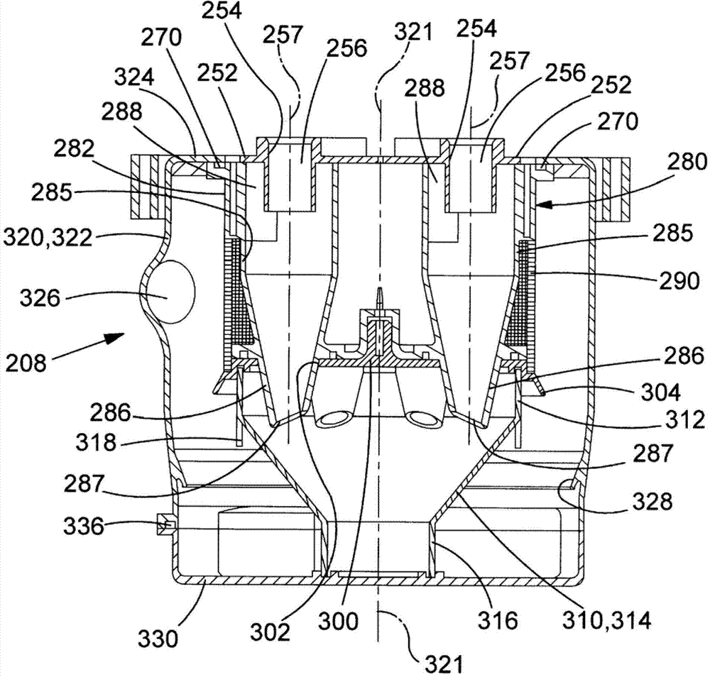
图12示出图10中的旋风式分离装置的纵截面;Figure 12 shows a longitudinal section of the cyclonic separation device in Figure 10;
图13示出图12中的截面的透视图;Figure 13 shows a perspective view of the section in Figure 12;
图14示出图10中的电动机、风扇和旋风式分离装置的结构的纵截面;Fig. 14 shows the longitudinal section of the structure of the motor, fan and cyclone type separating device among Fig. 10;
图15示出图10中的电动机、风扇和旋风式分离装置的结构的分解透视图;Fig. 15 shows the exploded perspective view of the structure of motor, fan and cyclone type separating device among Fig. 10;
图16示出图10中的旋风式分离装置的内部部件的分解透视图;Figure 16 shows an exploded perspective view of the internal components of the cyclonic separation device in Figure 10;
图17A至图17F示出图12中的纵截面,包括在使用时穿过旋风式分离装置的结构的气流路径;Figures 17A to 17F show the longitudinal section in Figure 12, including the airflow path through the structure of the cyclonic separation device in use;
图18至图22示出图10中的旋风式分离装置的不同构造的图解示意图;Figures 18 to 22 show diagrammatic representations of different configurations of the cyclonic separation device in Figure 10;
图23示出具有电动机、风扇和旋风式分离装置的结构的手持式真空清洁器的第三实施例的透视图;Figure 23 shows a perspective view of a third embodiment of a hand-held vacuum cleaner with a structure of motor, fan and cyclonic separation device;
图24示出不带有污物容器壁的图23中的真空清洁器的透视图;Figure 24 shows a perspective view of the vacuum cleaner in Figure 23 without the dirt container wall;
图25示出涡流器的透视图;Figure 25 shows a perspective view of a swirler;
图26示出带有透明的污物容器壁的图23中的真空清洁器的透视图;Figure 26 shows a perspective view of the vacuum cleaner in Figure 23 with a transparent dirt container wall;
图27示出图26中的真空清洁器的包括气流路径的图解截面XXVI-XXVI;Figure 27 shows a diagrammatic section XXVI-XXVI of the vacuum cleaner in Figure 26 including the air flow path;
图28示出图27中的真空清洁器的包括气流路径的图解截面XXVII-XXVII;Figure 28 shows a diagrammatic section XXVII-XXVII of the vacuum cleaner in Figure 27 including the air flow path;
图29示出具有可伸长的污浊空气通道和图2至图9中的电动机、风扇和旋风式分离装置的结构的电池供电式真空清洁器的侧视图;Figure 29 shows a side view of a battery powered vacuum cleaner with an extendable dirty air passage and the configuration of the motor, fan and cyclonic separation device of Figures 2 to 9;
图30示出图29中的真空清洁器的透视图;Figure 30 shows a perspective view of the vacuum cleaner in Figure 29;
图31示出图29中的真空清洁器的一部分的剖视图,其中示出了电池组;Figure 31 shows a cross-sectional view of a portion of the vacuum cleaner of Figure 29 showing the battery pack;
图32示出污浊空气通道处于伸长状态的图29中的真空清洁器的透视图;Figure 32 shows a perspective view of the vacuum cleaner of Figure 29 with the dirty air channel in an extended state;
图33示出具有挠性软管和图2至图9中的电动机、风扇和旋风式分离装置的结构的电池供电式真空清洁器的侧视图;Figure 33 shows a side view of a battery powered vacuum cleaner with a flexible hose and the configuration of the motor, fan and cyclonic separation device of Figures 2-9;
图34示出图33中的真空清洁器的透视图;Figure 34 shows a perspective view of the vacuum cleaner in Figure 33;
图35示出具有可伸缩式主体和清洁器头的电池供电式真空清洁器的透视图,该真空清洁器具有图2至图9中的电动机、风扇和旋风式分离装置的结构;Figure 35 shows a perspective view of a battery powered vacuum cleaner with a retractable body and cleaner head having the motor, fan and cyclonic separation arrangement of Figures 2 to 9;
图36示出图35中的真空清洁器的放大透视图;Figure 36 shows an enlarged perspective view of the vacuum cleaner in Figure 35;
图37示出可伸缩式主体已缩回的图35中的真空清洁器的侧视图;Figure 37 shows a side view of the vacuum cleaner of Figure 35 with the retractable body retracted;
图38示出图2至图9中的可拆卸电池组和旋风式分离装置的透视图;Figure 38 shows a perspective view of the removable battery pack and cyclonic separation device of Figures 2-9;
图39示出具有圆筒形可充电电池的图38中的电池组的横截面XXXVIII-XXXVIII;Figure 39 shows cross-sections XXXVIII-XXXVIII of the battery pack in Figure 38 with cylindrical rechargeable cells;
图40示出具有板状可充电电池的图38中的电池组的横截面XXXVIII-XXXVIII;Figure 40 shows a cross-section XXXVIII-XXXVIII of the battery pack in Figure 38 with plate-shaped rechargeable cells;
图41示出具有圆筒形可充电电池的环形电池组的横截面;Figure 41 shows a cross-section of a ring-shaped battery pack with cylindrical rechargeable cells;
图42和图43示出具有板状可充电电池的环形电池组的横截面;以及Figures 42 and 43 show cross-sections of annular battery packs with plate-shaped rechargeable cells; and
图44示出与图2中的电动机在不同的操作条件下的温度有关的测试数据的表格。FIG. 44 shows a table of test data related to the temperature of the electric motor in FIG. 2 under different operating conditions.
具体实施方式 Detailed ways
参考图1,其中示出了手持式真空清洁器2的第一实施例,该手持式真空清洁器2包括:主体4;把手6,其与主体4连接;旋风式分离装置8,其安装在主体上并且横向跨过主体;以及污浊空气通道10,其一端具有污浊空气入口12。真空清洁器包括:电动机,其与风扇接合,该风扇用于产生流经真空清洁器的气流;以及可充电电池(未示出),其在通过接通/关断(on/off)开关14与电动机电连接时向电动机提供电能。Referring to Fig. 1, there is shown a first embodiment of a hand-held
参考图2至图8,其中示出了包括电动机16、风扇18和旋风式分离装置8的结构。电动机具有驱动轴20,驱动轴20具有中心轴线21。风扇是离心式风扇18,风扇具有面向电动机的轴向入口22以及切向出口24。风扇的直径为68mm。风扇安装在位于电动机顶部的驱动轴上。在使用时,电动机驱动风扇产生流经旋风式分离装置的气流,后文中将对此进行更详细地描述。驱动轴20的一小部分从电动机16的底部突出。在位于电动机的底部的驱动轴20上安装有第二风扇,第二风扇包括桨轮26。电动机和桨轮套入通常被称为“电动机罐(motor can)”的圆筒形电动机的外主体中。在使用时,电动机使桨轮旋转,以使电动机罐内部以及电动机底部周围的气流循环并增强。Referring to FIGS. 2 to 8 , there is shown a structure including a
电动机16和风扇18容纳在电动机风扇壳体27中,电动机风扇壳体27包括:大致圆筒形的主体部分28,其包围电动机;以及大致圆形的头部29,其包围风扇。头部29的直径大于主体部分28的直径。电动机风扇壳体27包括带孔端盖30,其安装在主体部分的与头部相反的一侧上。端盖30保护风扇。端盖具有布置成圆形阵列的孔眼36,气流从孔眼36附近排出风扇。头部用作引导来自风扇并离开孔眼的气流的导流板。主体部分具有:布置成阵列的底部槽32,其围绕电动机的底部布置;以及布置成阵列的顶部槽34,其位于驱动轴20从电动机的顶部突出的位置周围。The
旋风式分离装置8包括围绕电动机驱动轴20的中心轴线21布置的前置风扇过滤器40、涡流器组件50、大致圆筒形的内壁60、旋风分离器密封件70、旋风分离器组件80、圆筒形的带孔中间壁90、圆形隔板100、锥形漏斗110、透明的大致圆筒形的污物容器120以及圆形碗状门130。The
前置风扇过滤器40呈围绕电动机风扇壳体27的主体部分28的顶部气流槽34的环形形状。除了前置风扇过滤器与涡流器组件50连通之处以及前置风扇过滤器与主体部分28的顶部气流槽34连通之处以外,前置风扇过滤器容置在环形壳42中。这使得来自旋风式分离装置的气流流经前置风扇过滤器并流到风扇上。The
涡流器组件50包括平面环52,该平面环52上模制有十二个中空圆筒形涡流器54,这些涡流器54从平面环52的一侧突出。穿过涡流器的孔56穿透平面环的相对侧,即设置有前置风扇过滤器40的一侧。前置风扇过滤器40有助于抑制在空气流经涡流器孔56时因亥姆霍兹共振(Helmholtz resonance)而引起的高频声音。涡流器布置成围绕电动机驱动轴20的中心轴线21的圆形阵列。每个涡流器具有其自身的纵向中心轴线57,该纵向中心轴线57设置为与中心轴线21平行。涡流器可以具有沿着涡流器孔的纵向内部肋(未示出),以便进一步降低因亥姆霍兹共振而引起的高频噪声。纵向肋还趋向于将涡流器内的气流矫直,以便帮助降低空气流入前置风扇过滤器40时的能量损失。The
内壁60分为直径不同的两部分,每个部分呈大致圆筒形形状。内壁包括:环形凸缘62,其位于内壁的敞开端;中空的圆筒形杯64,其位于内壁的与敞开端相反的封闭端;中空的圆筒形壁66;以及环形肩部68。凸缘从圆筒形壁的敞开端径向向外延伸。圆筒形壁位于凸缘与圆筒形杯之间。圆筒形壁的直径大于圆筒形杯的直径。环形肩部将圆筒形壁与圆筒形杯连接到一起。肩部穿设有布置成圆形阵列的十二个孔69,十二个孔69围绕中心轴线21等角间隔地布置。环形凸缘62与污物容器120的环形顶壁121连接。The
涡流器组件50承座于圆筒形壁66中,并且平面环52面向肩部68并且涡流器54突伸穿过肩部的孔68。前置风扇过滤器40嵌设在圆筒形壁66内。电动机风扇壳体的主体部分28的底部嵌设在圆筒形杯64内。The
旋风分离器密封件70穿设有布置成圆形阵列的十二个孔72,十二个孔72围绕中心轴线21等角间隔地布置。内壁60的肩部68承座于旋风分离器密封件上。涡流器54突伸穿过密封件的孔72。The
旋风分离器组件80包括圆筒形环82和由该环所包围的布置成圆形阵列的十二个旋风分离器84。旋风分离器围绕中心轴线21等角间隔地布置。每个旋风分离器具有:中空的圆筒形顶部分85;以及中空的截锥形底部分86,其从圆筒形顶部分85垂下并且终止于位于旋风分离器底部的排出喷嘴87。
内壁60的肩部68隔着旋风分离器密封件70设置在旋风分离器组件80上。环82的外径与内壁60的圆筒形壁66的外径相同并且环82抵接圆筒形壁66。涡流器54突伸穿过旋风分离器密封件的孔72并且突伸到对应的旋风分离器84的圆筒形顶部分85内。穿过旋风分离器84的顶部的唯一通道经过其涡流器54,涡流器54用作通向前置风扇过滤器40的气流出口。每个涡流器与其所对应的旋风分离器同心。每个喷嘴87的平面相对于中心轴线57而倾斜。这有助于防止灰尘和污物颗粒在从喷嘴排出之后再次进入喷嘴。
每个旋风分离器84的圆筒形顶部分85具有空气入口88,空气入口88设置为切向穿过旋风分离器的一侧并且接近涡流器54。十二个空气入口与位于环82下方并且围绕旋风分离器84的分配腔室170连通,后文中将对此进行更详细地描述。The cylindrical
中间壁90设置在旋风分离器组件80上。中间壁90的外径与圆筒形环82的外径相同并且中间壁90抵接圆筒形环82。An
隔板100设置在中间壁90上并且隔板100的直径与中间壁90的直径大致相同。隔板100穿设有布置成圆形阵列的十二个孔102,十二个孔102围绕中心轴线21等角间隔地布置。旋风分离器84的排出喷嘴87突伸穿过对应的隔板孔102。隔板100具有从中心轴线21朝向碗状门130径向向外倾斜的周向唇部104。唇部104稍突出于中间壁90。The
锥形漏斗110包括中空的周向裙部112、从裙部垂下的截锥形锥部114以及从锥部垂下的中空的圆筒形鼻部116。裙部设置在隔板上并且裙部的外径与隔板的外径大致相同。锥部从隔板100朝向碗状门130径向向内地渐缩。裙部的穿孔部分118从锥部朝向碗状门130轴向向后地突出。
大致圆筒形的污物容器120包括:环形顶壁121;以及中空的圆筒形外壁122,其具有从外壁122垂下的截锥形污物收集碗124。污物容器具有设置为切向穿过外壁122的污浊空气入口126。污物容器120具有朝向中心轴线21并且朝向碗状门130径向向内地倾斜的周向唇部128。该唇部128从外壁与污物收集碗之间的过渡区稍向内突出。电动机风扇壳体的头部29嵌设在环形顶壁121的中央。环形顶壁与外壁122的周缘138可拆卸地连接。环形顶壁121可以通过扣合、卡合、互锁卡爪、过盈配合或者通过铰链与外壁122和内壁60连接。围绕环形顶壁设置有由聚乙烯、橡胶或者类似的弹性材料制成的弹性密封件,以确保环形顶壁与外壁的气密连接。The generally
碗状门130与污物收集碗124的外周缘132可拆卸地连接。碗状门抵接圆筒形鼻部116,从而将污物收集碗分为两个独立的腔室:位于锥形漏斗110内部的大致圆形的腔室134以及位于锥形漏斗外部的大致环形的腔室162。碗状门130可以通过扣合、卡合、互锁卡爪、过盈配合或者通过铰链与污物收集碗124连接。围绕碗状门130设置有由聚乙烯、橡胶或者类似的弹性材料制成的弹性密封件,以确保碗状门130与污物收集碗的气密连接。The
内壁60的环形凸缘62与从环形顶壁121的内侧突出的圆环123具有互补配合的关系。鼻部116与从碗状门130的内侧突出的圆环140具有互补配合的关系。这确保了当碗状门关闭时旋风式分离装置8的部件与中心轴线21保持同心。The
在环形顶壁121与碗状门130之间,旋风式分离装置8的不同部件(即:前置风扇过滤器40、涡流器组件50、内壁60、旋风分离器密封件70、旋风分离器组件80、中间壁90、隔板100、锥形漏斗110)通过可拆卸连接设置在彼此上,所述可拆卸连接典型地为扣合、卡合、互锁卡爪或过盈配合。这允许在不使用工具的情况下将旋风式分离装置8拆卸或重新组装,以便于清洁或更换旋风式分离装置8的单独部件。围绕环形凸缘62和环形壳42与环形顶壁121之间的连接部设置有由聚乙烯、橡胶或类似的弹性材料,或者由其他合适的密封材料制成的弹性密封件。这些弹性密封件确保了气密连接。污物容器120和碗状门130的内径足够大,从而能够经由污物容器的任一端将旋风式分离装置8的部件(即:前置风扇过滤器40、涡流器组件50、内壁60、旋风分离器密封件70、旋风分离器组件80、中间壁90、隔板100、锥形漏斗110)移除。Between the annular
在使用时,污浊气流在风扇18的作用下流入污浊空气入口12,穿过污浊空气通道10并流入旋风式分离装置8,在旋风式分离装置8内,气流中所夹带的灰尘和污物与气流分离。灰尘和污物被收集在旋风式分离装置内。空气从旋风式分离装置8流出,穿过前置风扇过滤器40,经由顶部槽34流入电动机风扇壳体27,穿过风扇18并从端盖30中的孔眼36流出。When in use, the dirty air flows into the dirty air inlet 12 under the action of the
参考图9A,旋风式分离装置8划分为第一旋风式分离单元160、第二旋风式分离单元150和分配腔室170。第一旋风式分离单元位于分配腔室上游的气流路径中。分配腔室位于第二旋风式分离单元上游的气流路径中。Referring to FIG. 9A , the
第一旋风式分离单元160包括圆筒形污物容器120。第二旋风式分离单元150包括布置成圆形阵列的十二个旋风分离器84。污物容器与电动机驱动轴20的中心轴线21同心。分配腔室170由内壁的中空的圆筒形杯64、旋风分离器组件80、中间壁90以及隔板100限定。第二旋风分离器单元150经由分配腔室170接收来自第一旋风分离器单元160的气流。The first
污物容器120的外壁122的直径为大约130mm。旋风分离器84的直径比污物容器的直径小得多。螺旋状的气流在旋风分离器中受到比在环形腔室中更大的离心力。因此,第二旋风式分离单元150的旋风分离器在组合时具有比第一旋风式分离单元160的污物容器更高的分离效率。The outer wall 122 of the
参考图9B至图9E更详细地描述穿过旋风式分离装置8的气流路径。The gas flow path through the
参考图9B,污浊空气(三头箭头)经由污浊空气入口126流入第一旋风式分离单元160。污浊空气入口126的切向结构使得污浊空气沿着围绕圆筒形污物容器120的螺旋状路径流动。这在污物容器内产生了外旋流。离心力使相对大的灰尘和污物颗粒向外移动以撞击污物容器的侧面并使相对大的灰尘和污物颗粒与气流分离。分离的灰尘和污物(D)朝向污物收集碗124回旋移动并沉积在污物收集碗124中。Referring to FIG. 9B , dirty air (three-headed arrow) flows into the first
参考图9C,部分被清洁的空气(双头箭头)自身发生逆流,以跟随紧密地围绕锥形漏斗的内螺旋状路径并朝向圆筒形的中间壁110流动。部分被清洁的空气基本畅通无阻地流经锥形漏斗的裙部112的穿孔部分118。隔板100的周向唇部104和污物容器120的唇部128在第一旋风式分离单元160中会聚为宽度限制X。该宽度限制将污物容器与中间壁之间的径向宽度减小了至少15%。该宽度限制朝向碗状门130而渐缩,使得空气及其所夹带的污物朝向碗状门移动能够比朝向相反方向移动更加容易。因此,周向唇部104、128和锥形漏斗的裙部112的穿孔部分118在分离的污物由部分被清洁的气流重新夹带之前将分离的污物捕捉到碗124中。部分被清洁的空气流经中间壁中的孔眼并流入分配腔室170,该中间壁过滤任何残余的大污物颗粒。Referring to FIG. 9C , the partially cleaned air (double-headed arrow) counterflows itself to follow an internal helical path that closely surrounds the conical funnel and flows towards the cylindrical
在图5中可以看出,十二个旋风分离器的空气入口88模制在旋风分离器组件80的环82内。分配腔室170与十二个旋风分离器84的空气入口88连通。参考图9D,在分配腔室中,部分被清洁的气流(双头箭头)将其自身在十二个空气入口88之间进行均分,并且从这十二个空气入口88流入第二旋风式分离单元150的十二个旋风分离器84内。空气入口88引导部分被清洁的空气沿着螺旋状路径围绕涡流器54流动。这在每个旋风分离器84内部产生了外旋流。离心力使灰尘和污物向外移动以撞击旋风分离器的侧面并使灰尘和污物与气流分离。分离的灰尘和污物朝向排出喷嘴87回旋移动。旋风分离器的截锥形部分86的内径随着气流接近喷嘴而减小。这将外螺旋气流加速,由此增大了离心力并从气流中分离出更小的灰尘和污物颗粒。灰尘和污物颗粒离开喷嘴以沉积在碗124的由锥形漏斗110限定的部分内。As can be seen in FIG. 5 , the
参考图9E,已清洁空气(单头箭头)自身发生逆流,以跟随窄的内螺旋状路径穿过旋风分离器84的中部。在风扇的作用下,已清洁空气从涡流器54的内部孔56流出并流入前置风扇过滤器40。前置风扇过滤器40去除经过旋风式分离装置8之后气流中残余的任何细小的灰尘和污物颗粒。Referring to FIG. 9E , the cleaned air (single-headed arrow) counterflows itself to follow a narrow inner helical path through the middle of the
前置风扇过滤器与电动机风扇壳体27连通。清洁的空气经由电动机风扇壳体中的顶部槽34流入风扇18的轴向入口22,流出风扇的切向出口24并穿过端盖30的孔眼36,由此从真空清洁器2排出。灰尘和污物被第一旋风式分离单元和第二旋风式分离单元分离出并且沉积在污物收集碗124中,可以通过打开碗状门130将污物收集碗124清空。The pre-fan filter communicates with the
返回图7,其中示出了污物容器120的环形顶壁121中的总共四个电动机冷却入口31中的三个。图7中,另一个电动机冷却入口被端盖30所遮挡。Returning to FIG. 7 , three of the total four
返回图8,其中示出了四个涡流器密封件58。每个涡流器密封件形成围绕三个连续的涡流器54的有肋的环。在四个涡流器密封件之间存在四个等角间隔的小的间隙59。涡流器密封件58对除了间隙59所在位置以外的涡流器组件50与内壁60之间的连接部进行密封。Returning to Figure 8, four
参考图9F,其中示了出清洁的电动机冷却空气(单头箭头)流经电动机16和风扇18的路径。四个电动机冷却入口与第一电动机冷却通道61a连通,第一电动机冷却通道61a位于前置风扇过滤器40的壳42与内壁60的圆筒形壁66之间。Referring to FIG. 9F , the path of clean motor cooling air (single headed arrow) through the
参考图9G,其中示出了在图9F的局部区域X中的涡流器54的纵截面。这里,涡流器密封件58阻止第一电动机冷却通道61a与第二电动机冷却通道61b之间的连通,第二电动机冷却通道61b位于电动机风扇壳体27与内壁60的圆筒形杯64之间。Referring to FIG. 9G , there is shown a longitudinal section of the
参考图9H,其中示出了在图9F的局部区域X中两个涡流器54与两个涡流器密封件58之间的纵截面。这里,涡流器密封件58之间的间隙59允许第一电动机冷却通道61a与第二电动机冷却通道61b之间的连通。Referring to FIG. 9H , there is shown a longitudinal section between two swirlers 54 and two
回到图9F,在使用时,清洁的电动机冷却空气在风扇的作用下流经四个电动机冷却入口31并沿着第一电动机冷却通道61a流动,穿过间隙59并沿着第二电动机冷却通道61b流动,电动机冷却空气从第二电动机冷却通道61b经由底部气流槽32进入电动机风扇壳体27。电动机包括位于电动机罐的底部的电动机通气孔17a和位于电动机罐的顶部的电动机通气孔17b,以便使电动机的内部通风。桨轮26使电动机底部周围的电动机冷却空气循环并增强。在风扇的作用下,电动机冷却空气流入底部电动机通气孔17a,穿过电动机的内部并穿出顶部电动机通气孔17b。电动机被电动机冷却气流冷却。电动机冷却气流路径汇入来自风扇18的轴向入口22周围的旋风式分离装置8的已清洁气流路径。电动机冷却气流从风扇的切向出口24排出并从端盖30的孔眼36流出。Returning to Figure 9F, in use, clean motor cooling air flows through the four
电动机冷却入口31围绕中心轴线21等角间隔地布置。电动机冷却入口与涡流器间隔密封件58之间的间隙59轴向对准,并且与电动机风扇壳体27中的底部气流槽32对准。该轴向对准有助于将沿着电动机冷却通道61a、61b的电动机冷却气流所遇到的任何阻力最小化。底部电动机通气孔17a也与电动机风扇壳体27的底部气流槽32对准,这有助于将电动机冷却气流所遇到的任何阻力最小化。The
清洁的电动机冷却气流路径与穿过旋风式分离装置8到达风扇18的轴向入口的气流路径分离。这对于真空清洁具有特定的益处。典型地,当风扇遇到体积气流的阻力时,电动机的速度增大,并且跨过风扇的压力相应地增大。可能发生这种现象的一个实例是当真空清洁器正在操作并且污浊空气入口与地毯、硬地板、窗帘或者限制气流的其它表面接触的时候。无论出于何种原因,如果穿过旋风式分离装置8的气流路径变堵塞或者受阻,则电动机冷却气流路径不一定会被堵塞或受阻。而是,增大的跨过风扇18的压力将增大穿过电动机冷却气流路径的吸力。这具有当电动机工作强度最高并且最需要冷却时增强电动机的冷却的优点。The clean motor cooling airflow path is separate from the airflow path through the
参考图44,其中示出了与电动机16的温度有关的测试数据的表格。当电动机驱动风扇18以产生气流时,两个热电偶安装在电动机罐上。旋风式分离装置8经历包含不同操作条件的三个单独的测试:(a)自由气流(污浊空气入口12完全打开);(b)旋风式分离装置的最大功率输出(气动功率);以及(c)密封的吸力(污浊空气入口12闭合)。本领域技术人员可以理解:气动功率是通过用体积流速(体积/时间)乘以吸力(力/面积)乘以基于湿度和大气压的校正系数而计算出的抽吸功率的测量值。在十分钟的运行时间之后测量环境温度并将其与电动机温度进行比较。在四个电动机冷却入口31打开的情况下执行三次测试,然后在四个电动机冷却入口31之一闭合的情况下重复测试。测试数据清楚地显示出电动机冷却气流路径的优点以及具有四个电动机冷却入口31的重要性。Referring to Figure 44, there is shown a table of test data relating to the temperature of the
参考图10和图11,其中示出了手持式真空清洁器202的第二实施例,该手持式真空清洁器202包括:主体204,其具有主轴线205;把手206;旋风式分离装置208,其相对于主轴线横向地安装在主体上;以及污浊空气通道210,其一端具有污浊空气入口212。真空清洁器包括:电动机216,其与风扇接合,该风扇用于产生流经真空清洁器的气流;以及可充电电池217,其在通过接通/关断开关214与电动机电连接时向电动机提供电能。Referring to Figures 10 and 11, there is shown a second embodiment of a
参考图12至图16,其中示出了包括电动机216、可充电电池217、风扇218、前置风扇过滤器240、旋风式分离装置的出口通道260和旋风式分离装置208的结构。Referring to FIGS. 12 to 16 , there is shown a structure including an
电动机具有驱动轴220,驱动轴220具有纵向中心轴线221。风扇是离心式风扇218,风扇具有背向电动机的轴向入口222以及切向出口224。风扇的直径为68mm。风扇安装在位于电动机顶部的驱动轴上。如在图11和图14中清晰地示出,电池217布置成围绕电动机216的圆形阵列并且电池的纵轴线与中心轴线221平行。在使用时,电动机驱动风扇产生流经旋风式分离装置的气流,后文中将对此进行更详细地描述。The electric motor has a
主体204包括中央壳体226、电动机壳体228、框架230和端盖232。风扇218容纳在中央壳体226中。中央壳体与把手206连接。电动机216和电池217容纳在电动机壳体228中。电动机壳体大致伸长,以适配电池的轮廓。端盖232与电动机壳体的装有风扇一端的相反端连接。端盖具有布置成圆形阵列的孔眼236。The
框架230将中央壳体226与旋风式分离装置208连接起来。框架的一端支撑前置风扇过滤器240,前置风扇过滤器240设置在风扇218的轴向入口222的前方。框架的另一端支撑旋风式分离装置。A
出口通道260由大致椭圆形的通道壁262限定,通道壁262设置在框架230上,以便在通道壁与框架之间形成该出口通道。出口通道260设置有气流路径,气流路径位于旋风式分离装置208与前置风扇过滤器240之间。通道壁可以从框架上拆卸下来。通道壁是透明的,以便于对前置风扇过滤器进行目视检查。如果前置风扇过滤器需要清洁或更换,可以将通道壁从框架上移除。The
旋风式分离装置208包括涡流器组件250、涡流器密封件270、旋风分离器组件280、圆筒形的带孔中间壁290、圆形隔板300、锥形漏斗310、具有纵向中心轴线321的透明的大致圆筒形的污物容器320以及圆形的污物收集碗330,所有这些部件围绕污物容器320的中心轴线321而布置。The
涡流器组件250包括大致圆形的平面基体252,该平面基体252具有六个中空的圆筒形涡流器254。每个涡流器具有中央通孔256以及该涡流器自身的中心轴线257。涡流器布置成围绕污物容器320的中心轴线321的圆形阵列。每个涡流器与中心轴线321平行。涡流器从基体的一侧突出。每个涡流器的一小部分还从基体的相反侧突出。涡流器可以具有沿着通孔的纵向内部肋(未示出),以便有助于抑制在空气流经涡流器通孔256时由亥姆霍兹共振引起的高频声音。The
旋风分离器组件280包括大致圆筒形的环282和由该环282所包围的布置成圆形阵列的六个旋风分离器284。旋风分离器围绕污物容器320的中心轴线321等角间隔地布置。每个旋风分离器具有:中空的圆筒形顶部分285;以及中空的截锥形底部分286,其从圆筒形顶部分285垂下并且终止于位于旋风分离器底部的排出喷嘴287。The
涡流器组件250设置在旋风分离器组件280的环282上。涡流器254突伸到对应的旋风分离器284的圆筒形顶部分285内。穿过旋风分离器284的顶部的唯一通道经过其涡流器254,涡流器254用作通向出口通道260的气流出口。每个涡流器与其所对应的旋风分离器同心。每个喷嘴287的平面相对于中心轴线257而倾斜。这有助于防止灰尘和污物颗粒在从喷嘴排出之后再次进入喷嘴。The
每个旋风分离器284的圆筒形顶部分285具有空气入口288,空气入口288设置为切向穿过旋风分离器的一侧并且接近涡流器254。六个空气入口与位于环282的下方并且围绕旋风分离器284的分配腔室370连通,后文中将对此进行更详细地描述。The cylindrical
中间壁290设置在旋风分离器组件280上。中间壁290的外径与圆筒形环282的外径大致相同并且中间壁290抵接圆筒形环282。
隔板300设置在中间壁290上并且隔板300的直径与中间壁290的直径大致相同。隔板300穿设有布置成圆形阵列的六个孔302,六个孔302围绕中心轴线321等角间隔地布置。旋风分离器284的排出喷嘴287突伸穿过对应的隔板孔302。隔板300具有从中心轴线321朝向收集碗330径向向外倾斜的周向唇部304。唇部304稍突出于中间壁290。The
锥形漏斗310包括中空的周向裙部312、从裙部垂下的截锥形锥部314以及从锥部垂下的中空的圆筒形鼻部316。裙部设置在隔板300上并且裙部的外径与隔板300的外径大致相同。锥部从隔板朝向收集碗330径向向内地渐缩。裙部的穿孔部分318从锥部朝向收集碗330轴向向后地突出。
大致圆筒形的污物容器320包括中空的圆筒形外壁322,该外壁322具有从外壁322的顶部径向向内地延伸的圆形肩部324。污物容器具有设置为切向穿过外壁322的污浊空气入口326。污浊空气入口与污浊空气通道210连通。外壁322与框架230可旋转地连接,使得旋风式分离装置208能够围绕其中心轴线321相对于主体204而旋转。污浊空气通道210可以随旋风式分离装置208一起旋转,如图11所示,图11示出了处于折叠位置的污浊空气通道。The generally
涡流器组件250的平面基体252嵌设在污物容器320的圆形肩部324中的孔内。旋风分离器组件280的环282抵接圆形肩部324。旋风分离器284位于污物容器320内部。The
污物收集碗330与污物容器320的外周缘332可拆卸地连接。污物收集碗抵接鼻部316,从而将污物容器和污物收集碗分为两个单独的腔室:位于锥形漏斗310内部的圆形腔室334和位于锥形漏斗外侧的大致环形的腔室362。污物收集碗330可以通过扣合、卡合、互锁卡爪、过盈配合或者通过铰链与污物容器的外周缘连接。围绕污物收集碗330设置有由聚乙烯、橡胶者类似的弹性材料制成的弹性密封件336,以确保污物收集碗330与污物容器的气密连接。The
污物容器320具有朝向收集碗330并朝中心轴线321径向向内地倾斜的环形唇部328。唇部328稍突出于外壁。唇部328接近碗330。The
锥形漏斗310的鼻部316与从污物收集碗330的内侧突出的圆环340具有互补配合的关系。这确保了旋风式分离装置208的部件与污物容器320的中心轴线321保持同心。The
在使用时,污浊空气在风扇218的作用下流入污浊空气入口212,穿过污浊空气通道210并流入旋风式分离装置208,在旋风式分离装置208内,气流中所夹带的灰尘和污物与气流分离。灰尘和污物被收集在旋风式分离装置内。空气从旋风式分离装置208流出,经过涡流器的通孔256,沿着出口通道260流动,穿过前置风扇过滤器240,穿过风扇218,经由电动机壳体228流经电动机216和电池单元217,并且从端盖232中的孔眼236流出。When in use, the dirty air flows into the
参考图17A,旋风式分离装置208划分为第一旋风式分离单元360、第二旋风式分离单元350和分配腔室370。第一旋风式分离单元位于分配腔室上游的气流路径中。分配腔室位于第二旋风式分离单元上游的气流路径中。Referring to FIG. 17A , the
第一旋风式分离单元360包括圆筒形污物容器310。第二旋风式分离单元350包括布置成圆形阵列的六个旋风分离器284。污物容器与污物容器的中心轴线321同心。分配腔室370由环282、旋风分离器组件280、中间壁290和隔板300限定。第二旋风式分离单元350经由分配腔室370接收来自第一旋风式分离单元360的气流。The first
污物容器320的外壁322的直径为大约120mm。旋风分离器284的直径小于环形腔室362的直径。螺旋状的气流在旋风分离器中受到比在污物容器中更大的离心力。因此,第二旋风式分离单元350的旋风分离器在组合时具有比第一旋风式分离单元360的污物容器更高的分离效率。The
参考图17B至图17F更详细地描述穿过旋风式分离装置208的气流路径。The gas flow path through the
参考图17B,污浊空气(三头箭头)从污浊空气通道210经由污浊空气入口326流入污物容器320。污浊空气入口326的切向结构使得污浊空气沿着围绕污物容器的螺旋状路径流动。这在污物容器内产生了外旋流。离心力使相对大的灰尘和污物(D)颗粒向外移动以撞击污物容器320的侧面并使相对大的灰尘和污物颗粒与气流分离。分离的灰尘和污物朝向污物收集碗330回旋移动并沉积在污物收集碗330中。Referring to FIG. 17B , dirty air (three-headed arrow) flows from the
参考图17C,部分被清洁的空气(双头箭头)自身发生逆流,以跟随紧密地围绕锥形漏斗310的内螺旋状路径并朝向圆筒形的中间壁290流动。部分被清洁的空气基本畅通无阻地流经锥形漏斗的裙部312的穿孔部分318。隔板300的周向唇部304和污物容器320的唇部328在第一旋风式分离单元360中会聚为宽度限制Y。该宽度限制将污物容器与中间壁之间的径向宽度减小了至少15%。该宽度限制朝向碗330而渐缩,使得空气及其所夹带的污物朝向碗状门移动能够比朝向相反方向移动更加容易。因此,周向唇部304、328和锥形漏斗的裙部312的穿孔部分318在分离的污物由部分被清洁的气流重新夹带之前将分离的污物捕捉到碗324中。部分被清洁的空气流经中间壁中的孔眼并流入分配腔室370,该中间壁过滤任何残余的大污物颗粒。Referring to FIG. 17C , partially cleaned air (double-headed arrow) counterflows itself to follow an internal helical path that closely surrounds the
在图16中可以看出,六个旋风分离器的空气入口288模制在旋风分离器组件280的环282内。分配腔室370与六个旋风分离器284的空气入口288连通。参考图17D,在分配腔室中,部分被清洁的气流(双头箭头)将其自身在六个空气入口288之间进行均分,并且从这六个空气入口288流入第二旋风式分离单元350的六个旋风分离器284内。空气入口288引导部分被清洁的气流沿着螺旋状路径围绕涡流器254流动。这在每个旋风分离器284内部产生了外旋流。离心力使灰尘和污物向外移动以撞击旋风分离器的侧面并使灰尘和污物与气流分离。分离的灰尘和污物朝向排出喷嘴287回旋移动。旋风分离器的截锥形部分286的内径随着气流接近喷嘴而减小。这将螺旋气流加速,由此增大了离心力并从气流中分离出更小的灰尘和污物颗粒。灰尘和污物颗粒离开喷嘴以沉积在碗330的由锥形漏斗310限定的部分内。As can be seen in FIG. 16 , the
参考图17E,已清洁空气(单头箭头)自身发生逆流,以跟随窄的内螺旋状路径穿过旋风分离器284的中部。在风扇的作用下,已清洁空气从涡流器254的内部通孔256流出。Referring to FIG. 17E , the cleaned air (single-headed arrow) counterflows itself to follow a narrow inner helical path through the middle of the
返回图17F,已清洁空气从涡流器254流入出口通道260并流至前置风扇过滤器240。前置风扇过滤器240去除经过旋风式分离装置208之后、到达风扇218之前的气流中残余的任何细小的灰尘和污物颗粒。清洁空气流入风扇218的轴向入口222并从风扇218的切向出口224排出。中央壳体226中的路径引导清洁气流从风扇流经电动机216和电池217,以便在空气从端盖232的孔眼236流出之前冷却电动机和电池。Returning to FIG. 17F , cleaned air flows from
灰尘和污物被第一旋风式分离单元和第二旋风式分离单元分离出并且沉积在污物收集碗330中,可以将污物收集碗330打开以进行清空。Dust and dirt are separated by the first and second cyclonic separation units and deposited in the
参考图18,其中示出了位于出口通道260、框架230、污物容器320和污物收集碗330的范围以内的旋风式分离装置208的不同部件(涡流器组件250、涡流器密封件270、旋风分离器组件280、中间壁290、隔板300、锥形漏斗310)的图解图。Referring to Figure 18, there is shown the different components of the cyclonic separation device 208 (swirl
涡流器密封件270以气密的方式密封涡流器组件250与污物容器320之间的连接部。出口通道密封件266以气密的方式密封框架230与出口通道壁262之间的连接部。涡流器密封件270和出口通道密封件266由聚乙烯、橡胶或者类似的弹性材料制成。The
旋风式分离装置208的某些部件典型地通过扣合、卡合、过盈配合或互锁卡爪而可拆卸地相连接。这允许在不使用工具的情况下将旋风式分离装置拆卸或重新组装,以便于清洁或更换旋风式分离装置的单独部件,如参考图19至图22所描述的那样。Certain components of the
参考图19,其中示出了拆卸旋风式分离装置208的第一构造的方法,由此可以将出口通道壁262从框架230上拆卸下来。污物容器320可以从框架上拆卸下来。涡流器组件可以单独或与污物容器一起从框架上拆卸下来。旋风分离器组件280、中间壁290、隔板300以及锥形漏斗310同样可以一体地从涡流器组件上拆卸下来。Referring to FIG. 19 , there is shown a method of disassembling the first configuration of the
污物收集碗330具有足够大的直径,从而当污物收集碗打开时,能够将旋风分离器组件280、中间壁290、隔板300以及锥形漏斗310从污物容器320中移除。
参考图20,其中示出了拆卸旋风式分离装置208的可选构造的方法,由此可以将出口通道壁262从框架230上拆卸下来。污物容器320可以从框架上拆卸下来。涡流器组件250、旋风分离器组件280、中间壁290、隔板300以及锥形漏斗310可以一体地从框架上拆卸下来,同时可以一并将污物容器拆卸下来或者不将污物容器拆卸下来。污物收集碗330可以打开以进行清空。Referring to FIG. 20 , there is shown a method of disassembling an alternative configuration of the
参考图21,其中示出了拆卸旋风式分离装置208的第二可选构造的方法,由此可以将出口通道壁262从框架230上拆卸下来。污物容器320、涡流器组件250、旋风分离器组件280、中间壁290、隔板300以及锥形漏斗310可以一体地从框架上拆卸下来。污物收集碗330可以打开以进行清空。Referring to FIG. 21 , there is shown a method of disassembling a second alternative configuration of the
参考图22,其中示出了拆卸旋风式分离装置208的第三可选构造的方法,由此可以将出口通道260(即,通道壁262和框架230)从框架上拆卸下来。污物容器320保持在框架上。当污物碗330被打开时,涡流器组件250、旋风分离器组件280、中间壁290、隔板300以及锥形漏斗310能够一体地从框架移除。Referring to Figure 22, there is shown a method of dismantling a third alternative configuration of the
参考图23,其中示出了手持式真空清洁器402的第三实施例,该手持式真空清洁器402包括具有把手406的主体404、安装在该主体上的旋风式分离装置408、以及在一端具有污浊空气入口412的污浊空气通道410。该真空清洁器包括电动机和可充电电池,该电动机与用于产生流经真空清洁器的气流的风扇接合,该可充电电池在通过接通/关断开关14与电动机电连接时向电动机提供电能。Referring to Figure 23, there is shown a third embodiment of a hand-held
参考图24至图27,其中示出了电动机416、可充电电池417、风扇418、前置风扇过滤器440、旋风式分离装置的出口通道460以及旋风式分离装置408的更多细节。Referring to Figures 24 to 27, further details of the
电动机具有驱动轴420。风扇418安装在位于电动机顶部的驱动轴上。风扇的直径为大约68mm。电池417围绕电动机416布置。在使用中,电动机驱动风扇以产生穿过旋风式分离装置的气流,后文中将对此进行更详细地描述。The electric motor has a
主体404包括中央壳体426和框架430。电动机416、风扇418和电池417容纳在中央壳体426中。该中央壳体与把手406连接。中央壳体在电动机底部附近具有布置成阵列的孔眼436。孔眼436用于从中央壳体排出气流。The
框架430将中央壳体426连接到旋风式分离装置408上。框架的一端支撑布置在风扇的入口前方的前置风扇过滤器440。框架的另一端支撑旋风式分离装置。该旋风式分离装置可旋转地连接到框架上。A
出口通道460包括布置在框架上的通道壁462以在通道壁与框架之间形成大约10mm深的通道。出口通道460提供旋风式分离装置408与前置风扇过滤器440之间的气流路径。该通道壁能够从框架拆卸下来。该通道壁是透明的以允许对前置风扇过滤器进行目视检查。围绕通道壁设置有由聚乙烯、橡胶或类似的弹性材料制成的弹性密封件,以确保通道壁与框架的气密连接。如果前置风扇过滤器需要清洁或更换则将通道壁从框架上移除。The
旋风式分离装置408包括涡流器组件450、旋风分离器组件480以及具有透明窗门530的细长的大致椭圆形污物容器520。The
涡流器组件450具有中空圆筒形涡流器452,该涡流器452包括锥形导流翼片454。该涡流器包括具有纵向中心轴线457的中心通孔456。该锥形导流翼片从涡流器的外表面径向突出。在本实施例中,该锥形导流翼片是三角形的,尽管其可以具有其它的锥形轮廓。导流翼片454的三角形轮廓是直角三角形。
旋风分离器组件480包括旋风分离器484和污浊空气入口488。该旋风分离器具有包括污浊空气入口的中空圆筒形主体485和截锥形底部主体486,该截锥形底部主体486从该圆筒形主体延伸并且终止于位于较窄端的排出喷嘴487。该空气入口布置成切向地穿过圆筒形主体的一侧。涡流器452布置在旋风分离器484的内部。该涡流器与该旋风分离器同心。导流翼片454相对于来自空气入口的气流的路径横向布置。该导流翼片的径向延伸的短边抵靠框架430。该导流翼片的顶点4541靠近空气入口。该导流翼片的斜边从顶点到涡流器的靠近排出喷嘴487的端部径向地向内渐缩。在顶点与旋风分离器484的圆筒形主体485之间存在大约5mm的小间隙Z。The
污物容器520在一端与中央壳体426连接而在另一端与旋风分离器484的排出喷嘴487连接。该污物容器包括跟随细长的大致椭圆形污物容器的外周的周壁522以及底壁524,并且圆筒形凹槽526从该底壁伸入到该污物容器的范围内。旋风分离器484在排出喷嘴487穿过底壁524突出的位置处与污物容器连通。在污物容器的相反侧电动机416的底部承座于圆筒形凹槽526内部,从而将真空清洁器的总宽度减小约20mm~25mm。The
旋风分离器484具有从排出喷嘴487轴向地伸入污物容器520的弯曲翼片490。该弯曲翼片在面对圆筒形凹槽526的一侧限定大约为喷嘴圆周一半的圆弧。该弯曲翼片的端部朝向喷嘴渐缩。污物容器具有从底壁524突出的平坦翼片492。该平坦翼片从圆筒形凹槽526的顶部切向地延伸至污物容器的大致中部。在正常使用中,该平坦翼片基本上与位于污物容器最上面的周壁522的相邻初始平坦部分522a平行。The
窗门530可拆卸地连接到容器520的周壁522上。窗门530可以通过扣合、互锁卡爪、铰链528或通过与污物容器的外壁过盈配合而连接到污物容器上。在示出的实例中,窗门由弹簧加载闩锁529牢固地保持为关闭状态。围绕窗门设置有由聚乙烯、橡胶或类似的弹性材料制成的弹性密封件(未示出),以确保窗门以气密的方式与污物容器520连接。通过打开窗门530能够清空由旋风式分离装置分离并沉积在污物容器520中的灰尘和污物。该窗门是透明的以便当污物容器520变满并且需要清空时能够对污物容器520进行目视检查。The
在使用中,污浊空气在风扇418的作用下流入污浊空气入口412、流经污浊空气入口通道410并且流入旋风式分离装置408,在旋风式分离装置408内,气流中所夹带的灰尘和污物与气流分离。灰尘和污物被收集在该旋风式分离装置中。空气经由涡流器的通孔456从旋风式分离装置408流出、沿着出口通道460流动、穿过前置风扇过滤器440、经由中央壳体426流经风扇418并且流过电动机416和电池417,然后从中央壳体中的孔眼436流出。In use, dirty air flows into the
参考图24、27和图28,更详细地描述了穿过旋风式分离装置408的气流。来自污浊空气通道410的污浊空气(三头箭头)经由空气入口488进入旋风分离器484的圆筒形主体485。空气入口488的切向结构和从涡流器452突出的三角形导流翼片454的存在而将污浊空气引导为沿着螺旋状路径围绕旋风分离器流动,并且将污浊空气朝向截锥形主体486然后朝向排出喷嘴引导。这在旋风分离器中产生了外旋流。离心力使较大的灰尘和污物颗粒向外移动以撞击旋风分离器的侧面并且将这些灰尘和污物颗粒与气流分离。分离的灰尘和污物朝向排出喷嘴487回旋移动并且进入污物容器520中。Referring to Figures 24, 27 and 28, the air flow through the
如图24所示,部分被清洁的气流(双头箭头)由弯曲翼片490和周壁522的近端弯曲部分522d引导并且沿着逆时针向上方向离开旋风分离器484。这有助于维持气流速度。平坦翼片492和凹槽526有助于以类似于双皮带轮传动的形式将部分被清洁的气流引导为跟随围绕污物容器520的周壁522的细长回路流动,在该双皮带轮传动的形式中,排出喷嘴487模拟位于一端的带轮,而凹槽526模拟位于相反端的带轮。例如,在正常使用中,气流的该细长回路从靠近周壁522的初始平坦部分522b的排出喷嘴开始并且在周壁522的远端弯曲部分522c内侧重定向以围绕凹槽526回转,并且继续朝向邻近于位于污物容器最下面的周壁的更远端平坦部分522d行进。该细长回路的延伸轴线大致穿过排出喷嘴和凹槽的中心。该平坦翼片和凹槽防止大量的灰尘和污物颗粒(D)在沉积于位于污物容器底部的周壁的更远端平坦部分522d上之前从循环的气流中掉落。周壁522具有与底壁524平行的大致菱形截面。周壁的初始平坦部分522a和更远端平坦部分522c向内渐缩并且远离周壁的远端弯曲部分522b。这促进了围绕污物容器的凹槽端沉积灰尘和污物,其中污物容器的凹槽端比污物容器的相反的排出喷嘴端具有更大的空间。此外,弯曲翼片490用作层流式气流进入排出喷嘴的障碍物。该气流被迫偏离该弯曲翼片。对该层流式气流的破坏促进任何残留的夹带的灰尘和污物(D)物沉积在污物容器中。因此,周壁522、平坦翼片492、凹槽526以及弯曲翼片490的形状组合起来以有助于从流向前置风扇过滤器440的气流路径中分离出任何残留的灰尘和污物。这提高了真空清洁器502的持续性能。As shown in FIG. 24 , partially cleaned airflow (double-headed arrow) is directed by
在偏离经过弯曲翼片490之后,清洁气流(单箭头)自身发生逆流并且在风扇的作用下在狭窄的内螺旋状路径流动以流入涡流器的通孔456,气流从该通孔456离开旋风式分离装置408并且进入入口通道460。After deflecting past
参考图29到图38,其中示出了具有第一实施例的电动机16、风扇18和旋风式分离装置8的结构的不同电池供电式真空清洁器。在所有的实例中,该结构布置有驱动轴20的中心轴线21,该中心轴线取向为横切真空清洁器的主体的主轴线。具体地,示出了具有可枢转污浊空气通道610的可手持式真空清洁器602;通过挠性软管710与清洁喷嘴712连接以模仿小型圆筒式清洁器的可手持式真空清洁器702;以及具有细长主体806、支撑轮807和清洁器头812以模仿立式真空清洁器(通常也称为“轻便清洁器”)的真空清洁器802。Referring to Figures 29 to 38, there are shown different battery powered vacuum cleaners having the
参考图29到图32,可手持式真空清洁器602包括具有主轴线605的主体604以及把手606。第一实施例的电动机16、风扇18和旋风式分离装置8在污物容器120的环形顶壁121处可旋转地连接到主体604上。该旋风式分离装置的中心轴线21取向为与主体的主轴线成直角(即,横切)。真空清洁器602包括具有可充电电池917的电池组900,以在在通过接通/关断开关14与电动机16电连接时向电动机16提供电能。污浊空气通道610与空气入口126连接。Referring to FIGS. 29-32 , the hand-held
特别参考图31,电池组900具有曲线型截面轮廓,该曲线型截面轮廓具有成形为配合在圆筒形污物容器120周围的曲线型内壁902。电池组900具有位于曲线型外壁906上的一对电触点904,以便在原位可以对这些电池进行充电。该电池组可拆卸地连接到污物容器120上。该电池组可以从污物容器120上拆卸下来以便能够根据需要更换这些电池或者在外部对这些电池进行充电。这些电池具有大致圆筒形形状。这些电池的纵向轴线布置成与电动机16的中心轴线21平行。With particular reference to FIG. 31 , the
污浊空气通道610、电池组900以及旋风式分离装置8能够从折叠位置围绕中心轴线21转过210°所对的圆弧。这允许真空清洁器602位于不同的方向,而用户能够将真空清洁器保持为同一取向。通过将主体604的主轴线605取向为适于用户并且将污浊空气入口612的位置调节为对准待清洁表面,而不是将主轴线取向为最适于待清洁表面并且要求用户将真空清洁器保持为满足该需求的取向,可以将真空清洁器用于接近较窄空间并且能够更舒适地把持真空清洁器。The
图29和图30示出了处于折叠位置的真空清洁器602,在该折叠位置,污浊空气通道以零度折叠于把手606下方,以便紧凑存放。电池组900旋转到污物容器120的直径上的相反侧。在图29示出的竖立位置,该真空清洁器可以支承于电池充电器916上。由于污浊空气通道折叠在把手下方,因此这允许真空清洁器以小的表面面积直立并且不需要过高的高度。通过这样布置,易于抓握真空清洁器。该真空清洁器的重心由于电池组而降低,从而使得竖立位置更稳定。此外,电池917通过电触点904与电池充电器916电连接,以便在竖立位置进行充电。Figures 29 and 30 show the
图32示出了处于伸长位置的真空清洁器602。污浊空气通道610从折叠位置旋转180°并且准备好投入使用。污浊空气通道610已被可伸缩地伸长为其长度的两倍。电池组900占据把手606与污物容器120之间的间隙616。电池组较重并且其在间隙616中的位置使得真空清洁器的重心移动靠近把手。这提高了真空清洁器的人体工程性。Figure 32 shows the
参考图33和图34,可手持式真空清洁器702包括带有把手706的主体704。电动机16、风扇18以及旋风式分离装置8在污物容器120的环形顶壁121处连接到主体704上。真空清洁器702包括具有可充电电池的电池组910。这些电池在通过接通/关断开关与电动机16电连接时向电动机16提供电能。空气入口126与挠性软管710的一端连接。清洁喷嘴712与挠性软管的另一端连接。Referring to FIGS. 33 and 34 , a
电池组910具有成形为支承于圆筒形污物容器120上的曲线型内壁902。该电池组可拆卸地连接到污物容器120上。可在原位对这些电池充电。该电池组可以从污物容器拆卸下来以便能够根据需要更换这些电池或者在外部对这些电池充电。该电池组具有一对支脚912,该对支脚布置成当真空清洁器702放置在平坦表面上时以稳定的方式支撑该真空清洁器702。这些电池具有大致圆筒形形状。这些电池的纵向轴线布置成与电动机16的中心轴线21平行。The
图32和图34示出了真空清洁器702的紧凑构造。挠性软管710经由电池组支脚912中的槽口914卷绕在污物容器120上并且位于电池组910下方。清洁喷嘴712由把手706支承。该把手是用具有自然弹性的塑料材料模制而成的。该清洁喷嘴由该把手握持。该清洁喷嘴能够容易地从把手拆卸下来以用于真空清洁。32 and 34 illustrate the compact construction of the
参考图35和图37,真空清洁器802包括细长主体804。该细长主体是可伸缩的。该细长主体在一端具有把手806而在另一端具有支架805。第一实施例的电动机16、风扇18和旋风式分离装置8在污物容器120的环形顶壁121处可旋转地连接到支架805上。该支架围绕污物容器的一侧弯成弓形以便污物容器的该一侧可以横向地连接到细长主体上。支撑轮807包围污物容器120。该支撑轮受到支撑以便通过轴承809围绕污物容器旋转。空气入口126与污浊空气通道810的一端连接。清洁器头812与污浊空气通道810的另一端连接。清洁器头812能够围绕污浊空气通道的纵向轴线8100相对于污物容器枢转。该污浊空气通道相对于污物容器切向地布置。Referring to FIGS. 35 and 37 , the
真空清洁器包括具有可充电电池917的电池组900以在通过接通/关断开关与电动机电连接时向电动机16提供电能。参考图37,电池组900具有成形为包围支撑轮807和圆筒形污物容器120的一部分的曲线型内壁902。该电池组可拆卸地连接到支架805上。可以在原位对电池917充电。该电池组可以从支架拆卸下来以便能够根据需要更换这些电池或者从外部对这些电池进行充电。这些电池具有大致圆筒形形状。这些电池的纵向轴线布置成与电动机16的中心轴线21平行。The vacuum cleaner includes a
返回图35,其中示出了准备好投入使用的真空清洁器802,其中支撑轮807和清洁头812位于地板上并且细长主体804处于完全伸长状态。支撑轮807布置成围绕污物容器的轴向长度的中点。支撑轮807的直径与污物容器120的轴向长度大致相等,以便细长主体能够左右双向都摆动约45°并且能够容易地操纵真空清洁器802。Returning to Figure 35, there is shown the
返回图37,其中示出了在细长主体804完全缩回至该细长主体的伸长长度的大约四分之一的情况下的真空清洁器。当该细长主体伸长时真空清洁器的总长度至少为当该细长主体缩回时真空清洁器的总长度的两倍。当细长主体缩回时,真空清洁器802准备好存放在厨柜中。该细长主体可以锁定在其缩回位置和伸长位置。本领域技术人员可以理解:任何适合的锁定系统将足以满足需要,例如,能够对应于缩回位置、伸长位置和缩回位置与伸长位置之间的任何中间位置而与沿着细长主体的孔互锁的弹簧加载卡爪。Returning to Fig. 37, there is shown the vacuum cleaner with the
参考图38,其中以透视的方式示出了电池组900,并且特别示出了将要包围或连接到旋风式分离装置8的污物容器120外部的曲线型内壁902。Referring to Figure 38, the
参考图39和图40,其中示出了沿着截面XXXVIII-XXXVIII的电池组900。市场上可买到的可充电电池可以具有圆筒形形状。图39示出了以弯曲阵列堆叠从而顺应电池组的曲线型截面轮廓的内腔五个圆筒形电池917。另外,市场上可买到的板状可充电电池927由挠性阳极板和阴极板或夹设有聚合物电解质材料和分离材料的阳极片、阴极片组成。阳极片与电池正极端子电连接而阴极片与电池负极端子连接,并且这些阳极片和阴极片能够串联或并联连接以形成电池组。这些板状电池是挠性的并且它们能够堆叠在彼此之上。图40示出了堆叠在彼此之上并且弯曲成顺应电池组的曲线型截面轮廓的内腔的三个板状电池927。Referring to Figures 39 and 40, there is shown the
参考图41至图43,其中以截面的方式示出了具有中空圆筒形内表面922的环形电池组920,该电池组920适于包围旋风式分离装置8的污物容器120。该环形电池组具有圆筒形内壁922和圆筒形外壁926。Referring to FIGS. 41 to 43 , there is shown in cross-section an
图41示出了布置成圆形阵列以顺应环形电池组920的环形截面轮廓的内腔的十二个圆筒形电池917。FIG. 41 shows twelve
图42示出了堆叠在彼此之上并且弯曲成中空圆筒形形状以顺应环形电池组920的环形截面的内腔的三个板状电池927。FIG. 42 shows three plate-shaped
图43示出了卷绕成中空圆筒形形状以顺应环形电池组920的环形截面的内腔的五个板状电池927。FIG. 43 shows five
弯曲的板状电池927通过消除自然地存在于圆筒形电池917之间的间隙而提高了对电池组920的内腔的使用。这实现了具有缩减的封装和更高能量密度的电池组的更紧凑设计。The
曲线型电池组900、910和环形电池组920的曲线型内壁或圆筒形内壁902、922包围污物容器120或将它们自身连接到污物容器120上。这有利于用于以紧凑方式容纳电池的新设计选择。The curvilinear or cylindrical
本领域技术人员可以理解:可充电电池可以是用于驱动电动机16、216和416的任何类型的能量蓄积器(包括可充电锂离子电池、镍氢或镍镉可充电电池)。Those skilled in the art will appreciate that the rechargeable battery may be any type of energy accumulator (including rechargeable Li-ion batteries, NiMH or NiCd rechargeable batteries) used to drive the
本领域技术人员可以理解:包括电动机16、216和416、风扇18、218和418以及旋风式分离装置8、208和408的结构的具体总体形状和尺寸能够根据将要使用这些结构中任何一种的真空清洁器的类型而改变。例如,各个结构特别是旋风式分离装置的总长度或宽度能够相对于其直径增加或减小,反之亦然。It will be appreciated by those skilled in the art that the specific general shape and dimensions of the structure comprising the
具体地,通过修改电池组910的形式以适合污物容器320的下侧,图33和图34的可手持式真空清洁器702能够被修改为包括该实施例的电动机216、风扇218以及旋风式分离装置208。挠性软管170将需要延长以卷绕到污物容器320、中央壳体226和电动机228上。Specifically, by modifying the form of the
此外,通过用中央壳体226和电动机壳体228代替主支架805,图35和图38的可手持式真空清洁器802能够被修改为包括第二实施例的电动机216、风扇218和旋风式分离装置208。这可以通过将细长主体804直接连接到中央壳体226上以代替把手206和支架805来实现。旋风式分离装置的出口通道260将需要延长以形成支撑轮807和轴承809包围污物容器320的足够间隙。Furthermore, the hand-held
上述讨论的电动机16、216和416是其驱动轴20、220和420与离心式风扇18、218和418直接接合的典型的直流有刷电动机。该电动机的驱动轴具有在每分钟转数转(rpm)为25,000到40,000的范围内的转速。具有在该范围内的转速的离心式风扇的外径是电动机罐的外径的大约两倍,以便具有足够的叶尖速度以产生穿过旋风式分离装置的所需体积流速。本领域技术人员可以理解:电动机16、216和416可以是由电子电路控制的直流电动机、交流电动机或多相异步电动机。永磁无刷电动机、开关磁阻电动机、磁通切换型磁阻电动机或其它无刷电动机类型可以具有在80,000至120,000rpm范围内的高转速。如果使用这种高速电动机,则风扇直径至少可以减半并且仍然能产生穿过旋风式分离装置的所需体积流速,这是由于风扇的叶尖速度很高的缘故。如果电动机在高转速范围的上限附近的转速下运行,则将使得风扇的外径与电动机罐的外径相等并且可能使得风扇的外径小于电动机罐的外径。在该高转速范围内的转速下运行的较小直径的风扇通常为叶轮,尽管其可以为轴流式风扇或离心式风扇。与高转速电动机的驱动轴接合的较小直径的风扇的外轮廓将是大致圆筒形的外轮廓。这提供了旋风式分离装置的布局的额外灵活性。The
在附图中未示出的旋风式分离装置8、208的第一或第二实施例的修改例中,旋风分离器84、284可以布置成容纳与风扇接合的高转速永磁无刷电动机、开关磁阻电动机或磁通切换型磁阻电动机,该风扇与电动机同轴并且该风扇的外径与电动机的外径基本上相等或小于电动机的外径。高速电动机和风扇的大致圆筒形的外轮廓可以在旋风分离器之中嵌入旋风式分离装置并且群集为大致圆形阵列。气流可以通过导流板引导到风扇的轴向入口并且从风扇的切向出口排出。高速电动机和风扇可以位于圆形阵列的圆周上,在这种情况下,来自风扇的气流可以从该圆形阵列的一侧排出并且被导出旋风式分离装置。高速电动机和风扇可以嵌设在该圆形阵列的中部或者该中部附近,在这种情况下,来自风扇的气流可以从该圆形阵列的一端排出并且被导出旋风式分离装置。如果高速电动机和风扇嵌设在相对于中心轴线倾斜的旋风式分离器的圆形阵列中(例如GB 2440 110A所披露的旋风式分离器的修改例),则来自风扇的气流可以从旋风式分离器的圆形阵列的一端或穿过旋风式分离器之间的间隙排出。In a modification of the first or second embodiment of the
Claims (14)
Applications Claiming Priority (2)
| Application Number | Priority Date | Filing Date | Title |
|---|---|---|---|
| EP11184790.1 | 2011-10-12 | ||
| EP11184790.1A EP2581018B1 (en) | 2011-10-12 | 2011-10-12 | Cyclonic separation apparatus |
Publications (2)
| Publication Number | Publication Date |
|---|---|
| CN103040413A true CN103040413A (en) | 2013-04-17 |
| CN103040413B CN103040413B (en) | 2016-11-30 |
Family
ID=
Cited By (54)
| Publication number | Priority date | Publication date | Assignee | Title |
|---|---|---|---|---|
| US9826868B2 (en) | 2009-03-13 | 2017-11-28 | Omachron Intellectual Property Inc. | Portable surface cleaning apparatus |
| US9883781B2 (en) | 2014-12-17 | 2018-02-06 | Omachron Intellectual Property Inc. | All in the head surface cleaning apparatus |
| US9949601B2 (en) | 2007-08-29 | 2018-04-24 | Omachron Intellectual Property Inc. | Cyclonic surface cleaning apparatus |
| US9962050B2 (en) | 2016-08-29 | 2018-05-08 | Omachron Intellectual Property Inc. | Surface cleaning apparatus |
| CN108176183A (en) * | 2018-02-28 | 2018-06-19 | 中国华能集团清洁能源技术研究院有限公司 | A kind of band devokes the tar filter and its method of work of eddy flow stator blade in advance |
| US10016106B1 (en) | 2016-12-27 | 2018-07-10 | Omachron Intellectual Property Inc. | Multistage cyclone and surface cleaning apparatus having same |
| US10022027B2 (en) | 2014-12-17 | 2018-07-17 | Omachron Intellectual Property Inc. | All in the head surface cleaning apparatus |
| US10080472B2 (en) | 2010-03-12 | 2018-09-25 | Omachron Intellectual Property Inc. | Hand carriable surface cleaning apparatus |
| US10136780B2 (en) | 2016-08-29 | 2018-11-27 | Omachron Intellectual Property Inc. | Surface cleaning apparatus |
| US10136779B2 (en) | 2016-08-29 | 2018-11-27 | Omachron Intellectual Property Inc. | Surface cleaning apparatus |
| CN109316117A (en) * | 2018-11-30 | 2019-02-12 | 追觅科技(天津)有限公司 | Dust catcher |
| US10258210B2 (en) | 2016-12-27 | 2019-04-16 | Omachron Intellectual Property Inc. | Multistage cyclone and surface cleaning apparatus having same |
| US10271704B2 (en) | 2016-12-27 | 2019-04-30 | Omachron Intellectual Property Inc. | Multistage cyclone and surface cleaning apparatus having same |
| US10271698B2 (en) | 2006-12-15 | 2019-04-30 | Omachron Intellectual Property Inc. | Surface cleaning apparatus |
| US10292550B2 (en) | 2016-08-29 | 2019-05-21 | Omachron Intellectual Property Inc. | Surface cleaning apparatus |
| US10299643B2 (en) | 2016-12-27 | 2019-05-28 | Omachron Intellectual Property Inc. | Multistage cyclone and surface cleaning apparatus having same |
| US10321794B2 (en) | 2016-08-29 | 2019-06-18 | Omachron Intellectual Property Inc. | Surface cleaning apparatus |
| US10405709B2 (en) | 2016-12-27 | 2019-09-10 | Omachron Intellectual Property Inc. | Multistage cyclone and surface cleaning apparatus having same |
| US10405711B2 (en) | 2016-08-29 | 2019-09-10 | Omachron Intellectual Property Inc. | Surface cleaning apparatus |
| US10413141B2 (en) | 2016-08-29 | 2019-09-17 | Omachron Intellectual Property Inc. | Surface cleaning apparatus |
| US10433689B2 (en) | 2016-08-29 | 2019-10-08 | Omachron Intellectual Property Inc. | Surface cleaning apparatus |
| US10441125B2 (en) | 2016-08-29 | 2019-10-15 | Omachron Intellectual Property Inc. | Surface cleaning apparatus |
| US10441124B2 (en) | 2016-08-29 | 2019-10-15 | Omachron Intellectual Property Inc. | Surface cleaning apparatus |
| US10499781B2 (en) | 2013-03-01 | 2019-12-10 | Omachron Intellectual Property Inc. | Surface cleaning apparatus |
| CN110710929A (en) * | 2019-11-08 | 2020-01-21 | 珠海格力电器股份有限公司 | Vacuum cleaners, separation assemblies and cyclones |
| CN110808022A (en) * | 2019-11-08 | 2020-02-18 | 中信戴卡股份有限公司 | Sound absorption device and vehicle wheel with same |
| US10602894B2 (en) | 2011-03-04 | 2020-03-31 | Omachron Intellectual Property Inc. | Portable surface cleaning apparatus |
| US10729295B2 (en) | 2016-08-29 | 2020-08-04 | Omachron Intellectual Property Inc. | Surface cleaning apparatus |
| US10827889B2 (en) | 2018-05-30 | 2020-11-10 | Omachron Intellectual Property Inc. | Surface cleaning apparatus |
| US10827891B2 (en) | 2016-12-27 | 2020-11-10 | Omachron Intellectual Property Inc. | Multistage cyclone and surface cleaning apparatus having same |
| CN112034472A (en) * | 2019-06-03 | 2020-12-04 | 亚洲光学股份有限公司 | Distance measuring device |
| US10932634B2 (en) | 2018-05-30 | 2021-03-02 | Omachron Intellectual Property Inc. | Surface cleaning apparatus |
| US11013378B2 (en) | 2018-04-20 | 2021-05-25 | Omachon Intellectual Property Inc. | Surface cleaning apparatus |
| CN113633214A (en) * | 2016-03-31 | 2021-11-12 | Lg电子株式会社 | Hand-held vacuum cleaner |
| US11235339B2 (en) | 2018-09-21 | 2022-02-01 | Omachron Intellectual Property Inc. | Surface cleaning apparatus |
| US11246462B2 (en) | 2019-11-18 | 2022-02-15 | Omachron Intellectual Property Inc. | Multi-inlet cyclone |
| US11285495B2 (en) | 2016-12-27 | 2022-03-29 | Omachron Intellectual Property Inc. | Multistage cyclone and surface cleaning apparatus having same |
| US11571098B2 (en) | 2006-12-12 | 2023-02-07 | Omachron Intellectual Property Inc. | Hand vacuum cleaner |
| US11690489B2 (en) | 2009-03-13 | 2023-07-04 | Omachron Intellectual Property Inc. | Surface cleaning apparatus with an external dirt chamber |
| CN116439601A (en) * | 2022-01-06 | 2023-07-18 | 金华市金顺工具有限公司 | handheld vacuum cleaner |
| US11751740B2 (en) | 2019-11-18 | 2023-09-12 | Omachron Intellectual Property Inc. | Multi-inlet cyclone |
| US11751733B2 (en) | 2007-08-29 | 2023-09-12 | Omachron Intellectual Property Inc. | Portable surface cleaning apparatus |
| US11857140B2 (en) | 2013-02-28 | 2024-01-02 | Omachron Intellectual Property Inc. | Cyclone such as for use in a surface cleaning apparatus |
| US11937758B2 (en) | 2016-03-31 | 2024-03-26 | Lg Electronics Inc. | Cleaner |
| US11992848B2 (en) | 2019-01-23 | 2024-05-28 | Omachron Intellectual Property Inc. | Surface cleaning apparatus |
| US11992169B2 (en) | 2016-03-31 | 2024-05-28 | Lg Electronics Inc. | Cleaner |
| US12004700B2 (en) | 2007-08-29 | 2024-06-11 | Omachron Intellectual Property Inc. | Cyclonic surface cleaning apparatus |
| US12048409B2 (en) | 2007-03-11 | 2024-07-30 | Omachron Intellectual Property Inc. | Portable surface cleaning apparatus |
| US12070176B2 (en) | 2006-12-15 | 2024-08-27 | Omachron Intellectual Property Inc. | Surface cleaning apparatus |
| US12082759B2 (en) | 2017-09-15 | 2024-09-10 | Omachron Intellectual Property Inc. | Surface cleaning apparatus |
| US12220099B2 (en) | 2006-12-12 | 2025-02-11 | Omachron Intellectual Property Inc. | Surface cleaning apparatus |
| US12446739B2 (en) | 2009-03-11 | 2025-10-21 | Omachron Intellectual Property Inc. | Hand vacuum cleaner |
| US12539004B2 (en) | 2009-03-13 | 2026-02-03 | Omachron Intellectual Property Inc. | Surface cleaning apparatus with different cleaning configurations |
| US12543905B2 (en) | 2020-10-21 | 2026-02-10 | Omachron Intellectual Property Inc. | Surface cleaning apparatus |
Citations (9)
| Publication number | Priority date | Publication date | Assignee | Title |
|---|---|---|---|---|
| US20040040270A1 (en) * | 2002-08-29 | 2004-03-04 | Mineyuki Inoue | Cyclonic vacuum cleaner |
| CN1654004A (en) * | 2005-03-01 | 2005-08-17 | 泰怡凯电器(苏州)有限公司 | Cyclone barrel of vacuum cleaner |
| WO2006026414A2 (en) * | 2004-08-26 | 2006-03-09 | Euro-Pro Operating, Llc | Cyclonic separation device for a vacuum cleaner |
| CN1871071A (en) * | 2003-11-08 | 2006-11-29 | 戴森技术有限公司 | Cyclonic separating apparatus |
| US20070067944A1 (en) * | 2005-09-28 | 2007-03-29 | Panasonic Corporation Of North America | Vacuum cleaner with dirt collection vessel having a stepped sidewall |
| EP2055220A2 (en) * | 2007-11-05 | 2009-05-06 | Samsung Gwangju Electronics Co., Ltd. | Vacuum cleaner |
| US20090133370A1 (en) * | 2006-02-24 | 2009-05-28 | Samsung Gwangju Electronics Co., Ltd. | Cyclone dust collecting apparatus for vacuum cleaner |
| WO2009104959A1 (en) * | 2008-02-18 | 2009-08-27 | Jadyba B.V. | Gas cleaner for at least partially separating entrained components from a contaminated gas flow |
| CN101292851B (en) * | 2007-04-24 | 2010-11-03 | 三星光州电子株式会社 | Multi-cyclone dust separation equipment for vacuum cleaners |
Patent Citations (9)
| Publication number | Priority date | Publication date | Assignee | Title |
|---|---|---|---|---|
| US20040040270A1 (en) * | 2002-08-29 | 2004-03-04 | Mineyuki Inoue | Cyclonic vacuum cleaner |
| CN1871071A (en) * | 2003-11-08 | 2006-11-29 | 戴森技术有限公司 | Cyclonic separating apparatus |
| WO2006026414A2 (en) * | 2004-08-26 | 2006-03-09 | Euro-Pro Operating, Llc | Cyclonic separation device for a vacuum cleaner |
| CN1654004A (en) * | 2005-03-01 | 2005-08-17 | 泰怡凯电器(苏州)有限公司 | Cyclone barrel of vacuum cleaner |
| US20070067944A1 (en) * | 2005-09-28 | 2007-03-29 | Panasonic Corporation Of North America | Vacuum cleaner with dirt collection vessel having a stepped sidewall |
| US20090133370A1 (en) * | 2006-02-24 | 2009-05-28 | Samsung Gwangju Electronics Co., Ltd. | Cyclone dust collecting apparatus for vacuum cleaner |
| CN101292851B (en) * | 2007-04-24 | 2010-11-03 | 三星光州电子株式会社 | Multi-cyclone dust separation equipment for vacuum cleaners |
| EP2055220A2 (en) * | 2007-11-05 | 2009-05-06 | Samsung Gwangju Electronics Co., Ltd. | Vacuum cleaner |
| WO2009104959A1 (en) * | 2008-02-18 | 2009-08-27 | Jadyba B.V. | Gas cleaner for at least partially separating entrained components from a contaminated gas flow |
Cited By (88)
| Publication number | Priority date | Publication date | Assignee | Title |
|---|---|---|---|---|
| US12220099B2 (en) | 2006-12-12 | 2025-02-11 | Omachron Intellectual Property Inc. | Surface cleaning apparatus |
| US11571098B2 (en) | 2006-12-12 | 2023-02-07 | Omachron Intellectual Property Inc. | Hand vacuum cleaner |
| US12070176B2 (en) | 2006-12-15 | 2024-08-27 | Omachron Intellectual Property Inc. | Surface cleaning apparatus |
| US10314447B2 (en) | 2006-12-15 | 2019-06-11 | Omachron Intellectual Property Inc. | Surface cleaning apparatus |
| US10271698B2 (en) | 2006-12-15 | 2019-04-30 | Omachron Intellectual Property Inc. | Surface cleaning apparatus |
| US10327607B2 (en) | 2006-12-15 | 2019-06-25 | Omachron Intellectual Property Inc. | Surface cleaning apparatus |
| US12048409B2 (en) | 2007-03-11 | 2024-07-30 | Omachron Intellectual Property Inc. | Portable surface cleaning apparatus |
| US11229335B2 (en) | 2007-08-29 | 2022-01-25 | Omachron Intellectual Property Inc. | Cyclonic surface cleaning apparatus |
| US11751733B2 (en) | 2007-08-29 | 2023-09-12 | Omachron Intellectual Property Inc. | Portable surface cleaning apparatus |
| US12004700B2 (en) | 2007-08-29 | 2024-06-11 | Omachron Intellectual Property Inc. | Cyclonic surface cleaning apparatus |
| US9949601B2 (en) | 2007-08-29 | 2018-04-24 | Omachron Intellectual Property Inc. | Cyclonic surface cleaning apparatus |
| US12324557B2 (en) | 2007-08-29 | 2025-06-10 | Omachron Intellectual Property Inc. | Portable surface cleaning apparatus |
| US12446739B2 (en) | 2009-03-11 | 2025-10-21 | Omachron Intellectual Property Inc. | Hand vacuum cleaner |
| US10548442B2 (en) | 2009-03-13 | 2020-02-04 | Omachron Intellectual Property Inc. | Portable surface cleaning apparatus |
| US11330944B2 (en) | 2009-03-13 | 2022-05-17 | Omachron Intellectual Property Inc. | Portable surface cleaning apparatus |
| US12539004B2 (en) | 2009-03-13 | 2026-02-03 | Omachron Intellectual Property Inc. | Surface cleaning apparatus with different cleaning configurations |
| US10080473B2 (en) | 2009-03-13 | 2018-09-25 | Omachron Intellectual Property Inc. | Hand vacuum cleaner |
| US11950751B2 (en) | 2009-03-13 | 2024-04-09 | Omachron Intellectual Property Inc. | Surface cleaning apparatus with an external dirt chamber |
| US11690489B2 (en) | 2009-03-13 | 2023-07-04 | Omachron Intellectual Property Inc. | Surface cleaning apparatus with an external dirt chamber |
| US12251074B2 (en) | 2009-03-13 | 2025-03-18 | Omachron Intellectual Property Inc. | Surface cleaning apparatus with an external dirt chamber |
| US11622659B2 (en) | 2009-03-13 | 2023-04-11 | Omachron Intellectual Property Inc. | Portable surface cleaning apparatus |
| US9826868B2 (en) | 2009-03-13 | 2017-11-28 | Omachron Intellectual Property Inc. | Portable surface cleaning apparatus |
| US11529031B2 (en) | 2009-03-13 | 2022-12-20 | Omachron Intellectual Property Inc. | Portable surface cleaning apparatus |
| US10080472B2 (en) | 2010-03-12 | 2018-09-25 | Omachron Intellectual Property Inc. | Hand carriable surface cleaning apparatus |
| US10602894B2 (en) | 2011-03-04 | 2020-03-31 | Omachron Intellectual Property Inc. | Portable surface cleaning apparatus |
| US11612283B2 (en) | 2011-03-04 | 2023-03-28 | Omachron Intellectual Property Inc. | Surface cleaning apparatus |
| US11857140B2 (en) | 2013-02-28 | 2024-01-02 | Omachron Intellectual Property Inc. | Cyclone such as for use in a surface cleaning apparatus |
| US12357140B2 (en) | 2013-02-28 | 2025-07-15 | Omachron Intellectual Property Inc. | Cyclone such as for use in a surface cleaning apparatus |
| US10499781B2 (en) | 2013-03-01 | 2019-12-10 | Omachron Intellectual Property Inc. | Surface cleaning apparatus |
| US11013383B2 (en) | 2014-12-17 | 2021-05-25 | Omachron Intellectual Property Inc. | All in the head surface cleaning apparatus |
| US11786095B2 (en) | 2014-12-17 | 2023-10-17 | Omachron Intellectual Property Inc. | Surface cleaning apparatus |
| US9883781B2 (en) | 2014-12-17 | 2018-02-06 | Omachron Intellectual Property Inc. | All in the head surface cleaning apparatus |
| US12484749B2 (en) | 2014-12-17 | 2025-12-02 | Omachron Intellectual Property Inc. | Surface cleaning apparatus |
| US10022027B2 (en) | 2014-12-17 | 2018-07-17 | Omachron Intellectual Property Inc. | All in the head surface cleaning apparatus |
| CN113633214A (en) * | 2016-03-31 | 2021-11-12 | Lg电子株式会社 | Hand-held vacuum cleaner |
| US12318056B2 (en) | 2016-03-31 | 2025-06-03 | Lg Electronics Inc. | Cleaner |
| US12064079B2 (en) | 2016-03-31 | 2024-08-20 | Lg Electronics Inc. | Cleaner |
| US12070179B2 (en) | 2016-03-31 | 2024-08-27 | Lg Electronics Inc. | Cleaner |
| US12004701B2 (en) | 2016-03-31 | 2024-06-11 | Lg Electronics Inc. | Cleaner |
| US12121199B2 (en) | 2016-03-31 | 2024-10-22 | Lg Electronics Inc. | Cleaner |
| US12053137B2 (en) | 2016-03-31 | 2024-08-06 | Lg Electronics Inc. | Cleaner |
| US11937758B2 (en) | 2016-03-31 | 2024-03-26 | Lg Electronics Inc. | Cleaner |
| CN113633214B (en) * | 2016-03-31 | 2023-07-21 | Lg电子株式会社 | Hand-held dust collector |
| US12446741B2 (en) | 2016-03-31 | 2025-10-21 | Lg Electronics Inc. | Cleaner |
| US11963654B2 (en) | 2016-03-31 | 2024-04-23 | Lg Electronics Inc. | Cleaner |
| US12478231B2 (en) | 2016-03-31 | 2025-11-25 | Lg Electronics Inc. | Cleaner |
| US11992169B2 (en) | 2016-03-31 | 2024-05-28 | Lg Electronics Inc. | Cleaner |
| US12011135B2 (en) | 2016-03-31 | 2024-06-18 | Lg Electronics Inc. | Cleaner |
| US10413141B2 (en) | 2016-08-29 | 2019-09-17 | Omachron Intellectual Property Inc. | Surface cleaning apparatus |
| US10321794B2 (en) | 2016-08-29 | 2019-06-18 | Omachron Intellectual Property Inc. | Surface cleaning apparatus |
| US9962050B2 (en) | 2016-08-29 | 2018-05-08 | Omachron Intellectual Property Inc. | Surface cleaning apparatus |
| US10136780B2 (en) | 2016-08-29 | 2018-11-27 | Omachron Intellectual Property Inc. | Surface cleaning apparatus |
| US10136779B2 (en) | 2016-08-29 | 2018-11-27 | Omachron Intellectual Property Inc. | Surface cleaning apparatus |
| US10292550B2 (en) | 2016-08-29 | 2019-05-21 | Omachron Intellectual Property Inc. | Surface cleaning apparatus |
| US10405711B2 (en) | 2016-08-29 | 2019-09-10 | Omachron Intellectual Property Inc. | Surface cleaning apparatus |
| US10433689B2 (en) | 2016-08-29 | 2019-10-08 | Omachron Intellectual Property Inc. | Surface cleaning apparatus |
| US10441125B2 (en) | 2016-08-29 | 2019-10-15 | Omachron Intellectual Property Inc. | Surface cleaning apparatus |
| US10441124B2 (en) | 2016-08-29 | 2019-10-15 | Omachron Intellectual Property Inc. | Surface cleaning apparatus |
| US10729295B2 (en) | 2016-08-29 | 2020-08-04 | Omachron Intellectual Property Inc. | Surface cleaning apparatus |
| US10258210B2 (en) | 2016-12-27 | 2019-04-16 | Omachron Intellectual Property Inc. | Multistage cyclone and surface cleaning apparatus having same |
| US10016106B1 (en) | 2016-12-27 | 2018-07-10 | Omachron Intellectual Property Inc. | Multistage cyclone and surface cleaning apparatus having same |
| US11938491B2 (en) | 2016-12-27 | 2024-03-26 | Omachron Intellectual Property Inc. | Surface cleaning apparatus |
| US10405709B2 (en) | 2016-12-27 | 2019-09-10 | Omachron Intellectual Property Inc. | Multistage cyclone and surface cleaning apparatus having same |
| US11673148B2 (en) | 2016-12-27 | 2023-06-13 | Omachron Intellectual Property Inc. | Surface cleaning apparatus |
| US10827891B2 (en) | 2016-12-27 | 2020-11-10 | Omachron Intellectual Property Inc. | Multistage cyclone and surface cleaning apparatus having same |
| US10299643B2 (en) | 2016-12-27 | 2019-05-28 | Omachron Intellectual Property Inc. | Multistage cyclone and surface cleaning apparatus having same |
| US11285495B2 (en) | 2016-12-27 | 2022-03-29 | Omachron Intellectual Property Inc. | Multistage cyclone and surface cleaning apparatus having same |
| US11331680B2 (en) | 2016-12-27 | 2022-05-17 | Omachron Intellectual Property Inc. | Surface cleaning apparatus |
| US10271704B2 (en) | 2016-12-27 | 2019-04-30 | Omachron Intellectual Property Inc. | Multistage cyclone and surface cleaning apparatus having same |
| US12082759B2 (en) | 2017-09-15 | 2024-09-10 | Omachron Intellectual Property Inc. | Surface cleaning apparatus |
| CN108176183B (en) * | 2018-02-28 | 2023-07-14 | 中国华能集团清洁能源技术研究院有限公司 | A tar filter with a pre-decoking swirl air guide and its working method |
| CN108176183A (en) * | 2018-02-28 | 2018-06-19 | 中国华能集团清洁能源技术研究院有限公司 | A kind of band devokes the tar filter and its method of work of eddy flow stator blade in advance |
| US11930987B2 (en) | 2018-04-20 | 2024-03-19 | Omachron Intellectual Property Inc. | Surface cleaning apparatus |
| US11013378B2 (en) | 2018-04-20 | 2021-05-25 | Omachon Intellectual Property Inc. | Surface cleaning apparatus |
| US11375861B2 (en) | 2018-04-20 | 2022-07-05 | Omachron Intellectual Property Inc. | Surface cleaning apparatus |
| US11744421B2 (en) | 2018-05-30 | 2023-09-05 | Omachron Intellectual Property Inc. | Surface cleaning apparatus |
| US10827889B2 (en) | 2018-05-30 | 2020-11-10 | Omachron Intellectual Property Inc. | Surface cleaning apparatus |
| US10932634B2 (en) | 2018-05-30 | 2021-03-02 | Omachron Intellectual Property Inc. | Surface cleaning apparatus |
| US11235339B2 (en) | 2018-09-21 | 2022-02-01 | Omachron Intellectual Property Inc. | Surface cleaning apparatus |
| CN109316117A (en) * | 2018-11-30 | 2019-02-12 | 追觅科技(天津)有限公司 | Dust catcher |
| US11992848B2 (en) | 2019-01-23 | 2024-05-28 | Omachron Intellectual Property Inc. | Surface cleaning apparatus |
| CN112034472A (en) * | 2019-06-03 | 2020-12-04 | 亚洲光学股份有限公司 | Distance measuring device |
| CN110710929A (en) * | 2019-11-08 | 2020-01-21 | 珠海格力电器股份有限公司 | Vacuum cleaners, separation assemblies and cyclones |
| CN110808022A (en) * | 2019-11-08 | 2020-02-18 | 中信戴卡股份有限公司 | Sound absorption device and vehicle wheel with same |
| US11751740B2 (en) | 2019-11-18 | 2023-09-12 | Omachron Intellectual Property Inc. | Multi-inlet cyclone |
| US11246462B2 (en) | 2019-11-18 | 2022-02-15 | Omachron Intellectual Property Inc. | Multi-inlet cyclone |
| US12543905B2 (en) | 2020-10-21 | 2026-02-10 | Omachron Intellectual Property Inc. | Surface cleaning apparatus |
| CN116439601A (en) * | 2022-01-06 | 2023-07-18 | 金华市金顺工具有限公司 | handheld vacuum cleaner |
Also Published As
| Publication number | Publication date |
|---|---|
| AU2012238308A1 (en) | 2013-05-02 |
| EP3375341A2 (en) | 2018-09-19 |
| US9005325B2 (en) | 2015-04-14 |
| AU2012238308B2 (en) | 2016-12-15 |
| CA2791564C (en) | 2017-10-31 |
| EP3639716B2 (en) | 2025-09-03 |
| EP3375341A3 (en) | 2018-09-26 |
| CA2791564A1 (en) | 2013-04-12 |
| EP3639716B1 (en) | 2021-11-03 |
| EP2581018A1 (en) | 2013-04-17 |
| EP3639716A1 (en) | 2020-04-22 |
| US20130091661A1 (en) | 2013-04-18 |
| EP2581018B1 (en) | 2019-06-26 |
| EP3375341B1 (en) | 2019-12-11 |
Similar Documents
| Publication | Publication Date | Title |
|---|---|---|
| AU2012238307B2 (en) | Cyclonic separation apparatus | |
| AU2012238315B2 (en) | A motor, fan and cyclonic separation apparatus arrangement | |
| AU2012238313B2 (en) | A motor, fan and cyclonic separation apparatus arrangement | |
| AU2012233039B2 (en) | Cyclonic separation apparatus for a vacuum cleaner | |
| US9005324B2 (en) | Motor, fan and cyclonic separation apparatus arrangement for a vacuum cleaner | |
| US8595895B2 (en) | Hand-holdable vacuum cleaner | |
| CA2791564C (en) | Cyclonic separation apparatus | |
| AU2012238310B2 (en) | Cyclonic separation apparatus | |
| AU2012238309A1 (en) | Cyclonic separation apparatus | |
| AU2012238319A1 (en) | A vacuum cleaner |
Legal Events
| Date | Code | Title | Description |
|---|---|---|---|
| C06 | Publication | ||
| PB01 | Publication | ||
| C10 | Entry into substantive examination | ||
| SE01 | Entry into force of request for substantive examination | ||
| C14 | Grant of patent or utility model | ||
| GR01 | Patent grant | ||
| CF01 | Termination of patent right due to non-payment of annual fee | ||
| CF01 | Termination of patent right due to non-payment of annual fee |
Granted publication date: 20161130 Termination date: 20191012 |