CN102961183A - Ablation catheter for vein anatomies - Google Patents
Ablation catheter for vein anatomies Download PDFInfo
- Publication number
- CN102961183A CN102961183A CN201210316424XA CN201210316424A CN102961183A CN 102961183 A CN102961183 A CN 102961183A CN 201210316424X A CN201210316424X A CN 201210316424XA CN 201210316424 A CN201210316424 A CN 201210316424A CN 102961183 A CN102961183 A CN 102961183A
- Authority
- CN
- China
- Prior art keywords
- catheter
- distal
- proximal
- predetermined length
- generally
- Prior art date
- Legal status (The legal status is an assumption and is not a legal conclusion. Google has not performed a legal analysis and makes no representation as to the accuracy of the status listed.)
- Granted
Links
- 210000003462 vein Anatomy 0.000 title claims abstract description 9
- 238000002679 ablation Methods 0.000 title claims description 25
- 230000003902 lesion Effects 0.000 abstract description 15
- 230000006835 compression Effects 0.000 description 8
- 238000007906 compression Methods 0.000 description 8
- 239000000463 material Substances 0.000 description 8
- 210000003492 pulmonary vein Anatomy 0.000 description 8
- 229920002635 polyurethane Polymers 0.000 description 7
- 239000004814 polyurethane Substances 0.000 description 7
- 230000007704 transition Effects 0.000 description 7
- 239000012530 fluid Substances 0.000 description 6
- 238000000034 method Methods 0.000 description 6
- 230000010412 perfusion Effects 0.000 description 6
- BASFCYQUMIYNBI-UHFFFAOYSA-N platinum Chemical compound [Pt] BASFCYQUMIYNBI-UHFFFAOYSA-N 0.000 description 6
- 229920002614 Polyether block amide Polymers 0.000 description 4
- 238000003491 array Methods 0.000 description 4
- 210000002837 heart atrium Anatomy 0.000 description 4
- 238000002955 isolation Methods 0.000 description 4
- 229910001220 stainless steel Inorganic materials 0.000 description 4
- 239000010935 stainless steel Substances 0.000 description 4
- 206010003658 Atrial Fibrillation Diseases 0.000 description 3
- 239000004642 Polyimide Substances 0.000 description 3
- 208000011338 SATB2 associated disease Diseases 0.000 description 3
- 208000013959 SATB2-associated syndrome Diseases 0.000 description 3
- 210000003484 anatomy Anatomy 0.000 description 3
- 239000011248 coating agent Substances 0.000 description 3
- 238000000576 coating method Methods 0.000 description 3
- 239000003292 glue Substances 0.000 description 3
- 210000005246 left atrium Anatomy 0.000 description 3
- 238000013507 mapping Methods 0.000 description 3
- 229910052697 platinum Inorganic materials 0.000 description 3
- 229920001721 polyimide Polymers 0.000 description 3
- 235000011127 sodium aluminium sulphate Nutrition 0.000 description 3
- 238000001808 supercritical antisolvent technique Methods 0.000 description 3
- 229910001006 Constantan Inorganic materials 0.000 description 2
- RYGMFSIKBFXOCR-UHFFFAOYSA-N Copper Chemical group [Cu] RYGMFSIKBFXOCR-UHFFFAOYSA-N 0.000 description 2
- 239000000853 adhesive Substances 0.000 description 2
- 230000001070 adhesive effect Effects 0.000 description 2
- 230000000712 assembly Effects 0.000 description 2
- 238000000429 assembly Methods 0.000 description 2
- 230000002457 bidirectional effect Effects 0.000 description 2
- 230000015572 biosynthetic process Effects 0.000 description 2
- 238000010276 construction Methods 0.000 description 2
- 238000002594 fluoroscopy Methods 0.000 description 2
- PCHJSUWPFVWCPO-UHFFFAOYSA-N gold Chemical compound [Au] PCHJSUWPFVWCPO-UHFFFAOYSA-N 0.000 description 2
- 229910052737 gold Inorganic materials 0.000 description 2
- 239000010931 gold Substances 0.000 description 2
- 230000002262 irrigation Effects 0.000 description 2
- 238000003973 irrigation Methods 0.000 description 2
- WABPQHHGFIMREM-UHFFFAOYSA-N lead(0) Chemical compound [Pb] WABPQHHGFIMREM-UHFFFAOYSA-N 0.000 description 2
- 229910052751 metal Inorganic materials 0.000 description 2
- 239000002184 metal Substances 0.000 description 2
- 239000004033 plastic Substances 0.000 description 2
- 229920003023 plastic Polymers 0.000 description 2
- 230000002159 abnormal effect Effects 0.000 description 1
- 206010003119 arrhythmia Diseases 0.000 description 1
- 230000003126 arrythmogenic effect Effects 0.000 description 1
- 238000005452 bending Methods 0.000 description 1
- 230000036760 body temperature Effects 0.000 description 1
- 238000009833 condensation Methods 0.000 description 1
- 230000005494 condensation Effects 0.000 description 1
- 238000001816 cooling Methods 0.000 description 1
- 210000002310 elbow joint Anatomy 0.000 description 1
- 238000003780 insertion Methods 0.000 description 1
- 230000037431 insertion Effects 0.000 description 1
- 229910052741 iridium Inorganic materials 0.000 description 1
- GKOZUEZYRPOHIO-UHFFFAOYSA-N iridium atom Chemical compound [Ir] GKOZUEZYRPOHIO-UHFFFAOYSA-N 0.000 description 1
- 238000012986 modification Methods 0.000 description 1
- 230000004048 modification Effects 0.000 description 1
- 230000002107 myocardial effect Effects 0.000 description 1
- XEPXGZZWVKNRGS-GQYPCLOQSA-N n-[(3r,4s,5s,6r)-3,4,5-trihydroxy-6-(hydroxymethyl)oxan-2-yl]octanamide Chemical compound CCCCCCCC(=O)NC1O[C@H](CO)[C@@H](O)[C@H](O)[C@H]1O XEPXGZZWVKNRGS-GQYPCLOQSA-N 0.000 description 1
- 229910001000 nickel titanium Inorganic materials 0.000 description 1
- HLXZNVUGXRDIFK-UHFFFAOYSA-N nickel titanium Chemical compound [Ti].[Ti].[Ti].[Ti].[Ti].[Ti].[Ti].[Ti].[Ti].[Ti].[Ti].[Ni].[Ni].[Ni].[Ni].[Ni].[Ni].[Ni].[Ni].[Ni].[Ni].[Ni].[Ni].[Ni].[Ni] HLXZNVUGXRDIFK-UHFFFAOYSA-N 0.000 description 1
- 229910000510 noble metal Inorganic materials 0.000 description 1
- 231100000252 nontoxic Toxicity 0.000 description 1
- 230000003000 nontoxic effect Effects 0.000 description 1
- 230000037361 pathway Effects 0.000 description 1
- 230000002093 peripheral effect Effects 0.000 description 1
- 230000002035 prolonged effect Effects 0.000 description 1
- 230000001737 promoting effect Effects 0.000 description 1
- 230000033764 rhythmic process Effects 0.000 description 1
- 231100000241 scar Toxicity 0.000 description 1
- 239000000565 sealant Substances 0.000 description 1
- 239000012812 sealant material Substances 0.000 description 1
- 238000004904 shortening Methods 0.000 description 1
- 238000005476 soldering Methods 0.000 description 1
- 125000006850 spacer group Chemical group 0.000 description 1
- 230000008685 targeting Effects 0.000 description 1
- 230000002792 vascular Effects 0.000 description 1
Images


Classifications
-
- A—HUMAN NECESSITIES
- A61—MEDICAL OR VETERINARY SCIENCE; HYGIENE
- A61B—DIAGNOSIS; SURGERY; IDENTIFICATION
- A61B18/00—Surgical instruments, devices or methods for transferring non-mechanical forms of energy to or from the body
- A61B18/04—Surgical instruments, devices or methods for transferring non-mechanical forms of energy to or from the body by heating
- A61B18/12—Surgical instruments, devices or methods for transferring non-mechanical forms of energy to or from the body by heating by passing a current through the tissue to be heated, e.g. high-frequency current
- A61B18/14—Probes or electrodes therefor
- A61B18/1492—Probes or electrodes therefor having a flexible, catheter-like structure, e.g. for heart ablation
-
- A—HUMAN NECESSITIES
- A61—MEDICAL OR VETERINARY SCIENCE; HYGIENE
- A61B—DIAGNOSIS; SURGERY; IDENTIFICATION
- A61B17/00—Surgical instruments, devices or methods
- A61B2017/00017—Electrical control of surgical instruments
- A61B2017/00022—Sensing or detecting at the treatment site
- A61B2017/00084—Temperature
-
- A—HUMAN NECESSITIES
- A61—MEDICAL OR VETERINARY SCIENCE; HYGIENE
- A61B—DIAGNOSIS; SURGERY; IDENTIFICATION
- A61B17/00—Surgical instruments, devices or methods
- A61B17/00234—Surgical instruments, devices or methods for minimally invasive surgery
- A61B2017/00238—Type of minimally invasive operation
- A61B2017/00243—Type of minimally invasive operation cardiac
-
- A—HUMAN NECESSITIES
- A61—MEDICAL OR VETERINARY SCIENCE; HYGIENE
- A61B—DIAGNOSIS; SURGERY; IDENTIFICATION
- A61B17/00—Surgical instruments, devices or methods
- A61B2017/00831—Material properties
- A61B2017/00867—Material properties shape memory effect
-
- A—HUMAN NECESSITIES
- A61—MEDICAL OR VETERINARY SCIENCE; HYGIENE
- A61B—DIAGNOSIS; SURGERY; IDENTIFICATION
- A61B18/00—Surgical instruments, devices or methods for transferring non-mechanical forms of energy to or from the body
- A61B2018/00005—Cooling or heating of the probe or tissue immediately surrounding the probe
- A61B2018/00011—Cooling or heating of the probe or tissue immediately surrounding the probe with fluids
- A61B2018/00029—Cooling or heating of the probe or tissue immediately surrounding the probe with fluids open
- A61B2018/00035—Cooling or heating of the probe or tissue immediately surrounding the probe with fluids open with return means
-
- A—HUMAN NECESSITIES
- A61—MEDICAL OR VETERINARY SCIENCE; HYGIENE
- A61B—DIAGNOSIS; SURGERY; IDENTIFICATION
- A61B18/00—Surgical instruments, devices or methods for transferring non-mechanical forms of energy to or from the body
- A61B2018/00053—Mechanical features of the instrument of device
- A61B2018/00059—Material properties
- A61B2018/00065—Material properties porous
-
- A—HUMAN NECESSITIES
- A61—MEDICAL OR VETERINARY SCIENCE; HYGIENE
- A61B—DIAGNOSIS; SURGERY; IDENTIFICATION
- A61B18/00—Surgical instruments, devices or methods for transferring non-mechanical forms of energy to or from the body
- A61B2018/00315—Surgical instruments, devices or methods for transferring non-mechanical forms of energy to or from the body for treatment of particular body parts
- A61B2018/00345—Vascular system
- A61B2018/00351—Heart
- A61B2018/00375—Ostium, e.g. ostium of pulmonary vein or artery
-
- A—HUMAN NECESSITIES
- A61—MEDICAL OR VETERINARY SCIENCE; HYGIENE
- A61B—DIAGNOSIS; SURGERY; IDENTIFICATION
- A61B18/00—Surgical instruments, devices or methods for transferring non-mechanical forms of energy to or from the body
- A61B2018/00571—Surgical instruments, devices or methods for transferring non-mechanical forms of energy to or from the body for achieving a particular surgical effect
- A61B2018/00577—Ablation
-
- A—HUMAN NECESSITIES
- A61—MEDICAL OR VETERINARY SCIENCE; HYGIENE
- A61B—DIAGNOSIS; SURGERY; IDENTIFICATION
- A61B18/00—Surgical instruments, devices or methods for transferring non-mechanical forms of energy to or from the body
- A61B18/04—Surgical instruments, devices or methods for transferring non-mechanical forms of energy to or from the body by heating
- A61B18/12—Surgical instruments, devices or methods for transferring non-mechanical forms of energy to or from the body by heating by passing a current through the tissue to be heated, e.g. high-frequency current
- A61B18/14—Probes or electrodes therefor
- A61B2018/1467—Probes or electrodes therefor using more than two electrodes on a single probe
-
- A—HUMAN NECESSITIES
- A61—MEDICAL OR VETERINARY SCIENCE; HYGIENE
- A61B—DIAGNOSIS; SURGERY; IDENTIFICATION
- A61B18/00—Surgical instruments, devices or methods for transferring non-mechanical forms of energy to or from the body
- A61B18/04—Surgical instruments, devices or methods for transferring non-mechanical forms of energy to or from the body by heating
- A61B18/12—Surgical instruments, devices or methods for transferring non-mechanical forms of energy to or from the body by heating by passing a current through the tissue to be heated, e.g. high-frequency current
- A61B18/14—Probes or electrodes therefor
- A61B2018/1472—Probes or electrodes therefor for use with liquid electrolyte, e.g. virtual electrodes
Landscapes
- Health & Medical Sciences (AREA)
- Life Sciences & Earth Sciences (AREA)
- Surgery (AREA)
- Engineering & Computer Science (AREA)
- Plasma & Fusion (AREA)
- Medical Informatics (AREA)
- Otolaryngology (AREA)
- Physics & Mathematics (AREA)
- Cardiology (AREA)
- Biomedical Technology (AREA)
- Heart & Thoracic Surgery (AREA)
- Nuclear Medicine, Radiotherapy & Molecular Imaging (AREA)
- Molecular Biology (AREA)
- Animal Behavior & Ethology (AREA)
- General Health & Medical Sciences (AREA)
- Public Health (AREA)
- Veterinary Medicine (AREA)
- Surgical Instruments (AREA)
- Media Introduction/Drainage Providing Device (AREA)
Abstract
本发明涉及一种导管,所述导管适用于与携带于电极组件的大体上呈线性部分上的两个相对的环形电极同时进行组织接触,所述导管适用于横跨静脉口,以消融沿所述静脉口的弦的两个损伤灶,其中所述大体上呈线性的部分被稳定在所述静脉口上,以确保在沿导管主体的长度向下施加力时实现适当的组织接触。

The present invention relates to a catheter adapted for simultaneous tissue contact with two opposing ring-shaped electrodes carried on a generally linear portion of an electrode assembly, the catheter adapted to span the ostium of a vein to ablate Two lesions of the chord of the ostia on which the generally linear portion is stabilized to ensure proper tissue contact when force is applied down the length of the catheter body.
Description
技术领域 technical field
本发明整体涉及用于侵入式医学治疗的方法和装置,具体地讲,涉及导管,特别是灌注消融导管。The present invention relates generally to methods and devices for invasive medical treatment, and in particular to catheters, particularly perfusion ablation catheters.
背景技术 Background technique
心肌组织消融是熟知的心律失常的治疗方法。例如,在射频(RF)消融中,将导管插入心脏并在目标位置处与组织接触。然后通过导管上的电极施加RF能量,以便形成损伤灶,其目的是破坏组织中的致心律失常电流通路。Ablation of myocardial tissue is a well-known treatment for cardiac arrhythmias. For example, in radiofrequency (RF) ablation, a catheter is inserted into the heart and brought into contact with tissue at the target location. RF energy is then applied through electrodes on the catheter to create a lesion with the goal of disrupting the arrhythmogenic electrical pathway in the tissue.
具体地讲,心房纤颤是起源于心室(心脏顶部的腔室)的心律异常。许多脉冲并非按照顺序穿过心脏,而是从心房开始并穿过心房传播,导致心跳快速且紊乱。使用环状标测技术的四条肺静脉的消融也称作“肺静脉隔离术”(PVI),现已证实这种消融可成功用于治疗许多心房纤颤患者。Specifically, atrial fibrillation is an abnormal heart rhythm that originates in the ventricles (the chambers at the top of the heart). Many pulses travel through the heart not in sequence, but start from and travel through the atria, causing the heart to beat fast and turbulently. Ablation of four pulmonary veins using circular mapping, also known as "pulmonary vein isolation" (PVI), has proven successful in many patients with atrial fibrillation.
实现消融的方法是,从导管向心房中与肺静脉口相连的区域输送能量,从而在所述静脉口的周围形成圆形疤痕或损伤灶。所述损伤灶随后阻断来自肺静脉内的任何脉冲,从而防止心房纤颤的发生。该过程通常在所有四条肺静脉中重复。Ablation is achieved by delivering energy from a catheter to the region of the atrium connected to the ostium of the pulmonary veins, thereby creating a circular scar or lesion around the ostia. The lesion then blocks any pulses from within the pulmonary veins, thereby preventing atrial fibrillation from developing. This procedure is usually repeated in all four pulmonary veins.
消融主要借助于局灶性消融,即由导管远端处的尖端电极进行的消融,来实现。因此,对于沿直线或曲线的线性消融来说,在延长的消融期间,尖端电极被反复再定位或沿直线或曲线拖过组织。反复再定位或拖拽极为耗时,并且当在心房的小范围内进行操纵时,通常难以实现适当的组织接触。还已知一种灌注消融尖端电极和环形电极,这些电极能够在消融期间有效降低电极温度,以最小化烧焦和凝结物的形成。然而,对患者的流体负载是一个问题,特别是在多个电极受到灌注的情况下。Ablation is mainly achieved by means of focal ablation, ie ablation by a tip electrode at the distal end of the catheter. Thus, for linear ablation along a straight line or curve, the tip electrode is repeatedly repositioned or dragged through the tissue along a straight line or curve during prolonged ablation. Repeated repositioning or dragging is time consuming, and proper tissue contact is often difficult to achieve when maneuvering within the small confines of the atrium. Also known are irrigated ablation tip electrodes and ring electrodes that effectively reduce electrode temperature during ablation to minimize charring and coagulum formation. However, the fluid load on the patient is an issue, especially if multiple electrodes are perfused.
因此,需要一种无论静脉口的形状和尺寸如何,均适用于PVI手术的导管,这种导管能够改进导管的可操纵性以及静脉口的靶向性,进而改进损伤灶的形成并缩短消融手术的持续时间。具体地讲,需要一种具有多个环形电极的导管,这种导管能够通过使环形电极和静脉口之间能够同时存在两个接触位置,确保与静脉口的组织接触更大且更稳定。Therefore, there is a need for a catheter suitable for PVI procedures regardless of the shape and size of the ostium, which can improve the maneuverability of the catheter and the targeting of the ostium, thereby improving lesion formation and shortening the ablation procedure duration. In particular, there is a need for a catheter with multiple ring electrodes that ensures greater and more stable tissue contact with the ostium by enabling two simultaneous contact locations between the ring electrodes and the ostium.
发明内容 Contents of the invention
本发明涉及灌注消融导管,所述灌注消融导管具有电极组件,所述电极组件适用于静脉解剖结构以及相关手术,包括肺静脉隔离术(PVI)。所述电极组件具有带有多个环形电极(或环形电极阵列)的细长或线性部分。所述线性部分的长度跨越静脉直径,以使得所述线性部分可以通过至少两个环形电极同时与静脉口接触来压贴静脉口。随着ECG读数和荧光镜透视检查证实已实现适当接触,选择性地以单极和/或双极方式向所述环形电极供应能量,以进行消融,从而形成损伤灶来完成肺静脉的隔离。The present invention relates to perfusion ablation catheters having electrode assemblies suitable for use in venous anatomy and related procedures, including pulmonary vein isolation (PVI). The electrode assembly has an elongated or linear section with a plurality of ring electrodes (or arrays of ring electrodes). The length of the linear portion spans the diameter of the vein, so that the linear portion can be pressed against the ostium of the vein by simultaneously contacting the ostium of the vein with at least two ring electrodes. With ECG readings and fluoroscopy confirming that proper contact has been achieved, the ring electrodes are selectively energized in a monopolar and/or bipolar fashion for ablation to form a lesion to complete isolation of the pulmonary veins.
借助于线性部分上的多个环形电极,可选择性地向电极(多个电极)供应能量,以通过射频发生器中的控制器或开关箱来实现消融。基于ECG数据而确定与静脉口适当接触并处于适当定位的任意电极(多个电极)将用于进行消融。为了用大体上连续的环状损伤灶来完全圈闭静脉,可按照递增的方式旋转导管,直到完成180度旋转。在递增旋转期间,可形成两个损伤灶,两个接触电极处各有一个,每个损伤灶都从另一损伤灶处横跨静脉口。由于多个环形电极在线性部分的远端和近端处或附近被布置成第一和第二组或者阵列,因而不论多数静脉的形状或尺寸如何,所述电极组件都适用于PVI。事实上,本发明的导管可用于对包括共用静脉口在内的所有静脉解剖结构进行消融。By means of multiple ring electrodes on the linear section, energy can be selectively supplied to the electrode(s) for ablation via a controller or switch box in the RF generator. Any electrode(s) that are determined to be in proper contact with and positioned at the ostia based on the ECG data will be used to perform the ablation. To completely enclose the vein with a substantially continuous annular lesion, the catheter may be rotated in increments until a 180 degree rotation is complete. During the incremental rotation, two lesions may be formed, one at each of the two contact electrodes, each across the ostia from the other lesion. Since the plurality of ring electrodes are arranged in first and second sets or arrays at or near the distal and proximal ends of the linear portion, the electrode assembly is suitable for use in PVI regardless of the shape or size of the majority of veins. In fact, the catheter of the present invention can be used to ablate all venous anatomy including shared venous ostia.
在一项实施例中,本发明的导管包括细长主体和远侧电极组件,所述远侧电极组件包括大体上呈线性的远侧部分和大体上呈线性的近侧部分,所述远侧部分的长度大于近侧部分的长度,所述近侧部分和远侧部分由U形部分连接,并且所述近侧部分通过肘型连接器部分连接到所述导管。所述远侧部分和近侧部分大体上相互对齐,并且大体上垂直于所述导管的纵轴。所述导管也可包括邻近所述电极组件的中间偏转部分,用于实现所述电极组件的单向或双向偏转。In one embodiment, a catheter of the present invention includes an elongate body and a distal electrode assembly comprising a generally linear distal portion and a generally linear proximal portion, the distal The length of the portion is greater than the length of the proximal portion, the proximal portion and the distal portion are connected by a U-shaped portion, and the proximal portion is connected to the catheter by an elbow connector portion. The distal and proximal portions are generally aligned with each other and are generally perpendicular to the longitudinal axis of the catheter. The catheter may also include an intermediate deflection portion adjacent to the electrode assembly for unidirectional or bidirectional deflection of the electrode assembly.
在一项具体实施例中,整个远侧电极组件,包括大体上呈线性的远侧部分和近侧部分、U形部分以及肘型连接部分,大体上位于单个共用平面内。In a specific embodiment, the entire distal electrode assembly, including the generally linear distal and proximal portions, the U-shaped portion, and the elbow-shaped connection portion, lie generally within a single common plane.
在另一项具体实施例中,所述肘型连接部分具有在约30度与120度之间,更优选地为约90度的角。In another particular embodiment, said elbow connection portion has an angle of between about 30 degrees and 120 degrees, more preferably about 90 degrees.
在另一项具体实施例中,所述电极组件带有多个环形电极,这些环形电极的数量在约两个与十二个之间,优选地在约四个与八个之间,更优选地为约六个电极,其中一个环形电极组或阵列安装在大体上呈线性的远侧部分的远端处或附近,且另一环形电极组或阵列安装在大体上呈线性的远侧部分的近端处或附近。In another specific embodiment, the electrode assembly has a plurality of ring electrodes, the number of these ring electrodes is between about two and twelve, preferably between about four and eight, more preferably Ground is about six electrodes, wherein one ring electrode set or array is mounted at or near the distal end of the generally linear distal portion and the other ring electrode set or array is mounted at the end of the generally linear distal portion at or near the end.
附图说明 Description of drawings
结合附图阅读以下具体实施方式,将更好地理解本发明的这些和其他特征以及优点。应当理解,选定的结构和特征在某些附图中没有示出,以便更好地呈现其余的结构和特征。These and other features and advantages of the present invention will be better understood from the following detailed description when read in conjunction with the accompanying drawings. It should be understood that selected structures and features are not shown in some of the drawings in order to better present the remaining structures and features.
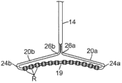
图1是根据本发明的导管的实施例的透视图。Figure 1 is a perspective view of an embodiment of a catheter according to the invention.
图2是位于静脉口上的适当定位处的图1所示导管的一部分的俯视平面图。Figure 2 is a top plan view of a portion of the catheter shown in Figure 1 in place on the ostium.
图3是沿线A--A截取的图2所示导管和静脉口的侧视图。Figure 3 is a side view of the catheter and venous port shown in Figure 2 taken along line A--A.
图4A是沿一直径截取的图1所示导管的侧视截面图,所述导管包括导管主体与中间偏转段的接合部。4A is a side cross-sectional view of the catheter shown in FIG. 1 taken along a diameter, the catheter including the junction of the catheter body and the intermediate deflection section.
图4B是沿另一直径截取的图1所示导管的侧视截面图,所述导管包括导管主体与中间偏转段的接合部。4B is a side cross-sectional view of the catheter shown in FIG. 1 taken along another diameter, the catheter including the junction of the catheter body and the intermediate deflection section.
图4C是图1所示导管的中间偏转段的实施例的端截面图。4C is an end cross-sectional view of an embodiment of an intermediate deflecting section of the catheter shown in FIG. 1 .
图5A是沿一直径截取的图1所示导管的侧视截面图,所述导管包括中间偏转段与远侧电极组件的接合部。5A is a side cross-sectional view of the catheter shown in FIG. 1 taken along a diameter, the catheter including the junction of the intermediate deflection section and the distal electrode assembly.
图5B是沿另一直径截取的图1所示导管的侧视截面图,所述导管包括中间偏转段与远侧电极组件的接合部。5B is a side cross-sectional view of the catheter shown in FIG. 1 taken along another diameter, the catheter including the junction of the intermediate deflection section and the distal electrode assembly.
图6A是沿一直径截取的图1所示电极组件的带电极远侧部分的侧视截面图。6A is a side cross-sectional view of the electroded distal portion of the electrode assembly shown in FIG. 1 taken along a diameter.
图6B是沿另一直径截取的图1所示电极组件的带电极远侧部分的侧视截面图。6B is a side cross-sectional view of the electroded distal portion of the electrode assembly shown in FIG. 1 taken along another diameter.
图6C是沿线C--C截取的图6A和图6B所示带电极远侧部分的端截面图。6C is an end cross-sectional view of the distal portion of the charged electrode shown in FIGS. 6A and 6B taken along line C--C.
图7是具有开口构型的远侧电极组件的替代实施例的侧视图。7 is a side view of an alternate embodiment of a distal electrode assembly having an open configuration.
图8是具有开口构型的远侧电极组件的其他替代实施例的侧视图。8 is a side view of another alternative embodiment of a distal electrode assembly having an open configuration.
图9是具有封闭构型的远侧电极组件的另一些其他替代实施例的侧视图。9 is a side view of still other alternative embodiments of a distal electrode assembly having a closed configuration.
图10是灌注环形电极的实施例的透视图。Figure 10 is a perspective view of an embodiment of a primed ring electrode.
图11是根据本发明实施例的心脏的示意性截面图,其中示出了导管插入左心房中。11 is a schematic cross-sectional view of a heart showing catheterization into the left atrium, according to an embodiment of the present invention.
具体实施方式 Detailed ways
本发明的导管适用于部署在身体目标区域(例如,心房)中,并设计成使用射频(RF)电流来促进静脉解剖结构(例如PV口)处或附近的消融。所述导管被有利地设计成通过位于大体上沿静脉口的任意弦(圆周上的两个位置)或直径的大体相对位置处的射频损伤灶(多个射频损伤灶),来进行肺静脉隔离。本发明的导管设有一种带有多个环形电极的细长或大体上呈线性的部分,该部分能够横跨静脉口,以实现在横跨静脉口的两个位置处同时与静脉口接触;通过提供所述部分,所述导管一旦放置于静脉口之上,就可保持相对稳定的定位,原因是所述导管被支撑在两个接触位置处,以接收沿导管的纵向长度施加的法向力,从而确保至少两个环形电极和静脉口之间适当地接触。通过使用ECG读数和荧光镜透视检查,操作人员可对导管进行操作,以通过与静脉口接触且作为单极电极的一个或多个选定环形电极而将RF能量输送到静脉口的接触组织,随后输送到返回电极(例如,附连到患者背部的外部电极贴片),从而形成局灶性单极损伤灶。如果适用或需要,与静脉口接触的选定环形电极也可作为双极电极而获得能量供应,以在获得能量供应的环形电极之间形成双极损伤灶。因此,可从由任意两个电极组成的电极对,或从多对电极将能量施加到任何单个电极。此外,通过围绕导管的纵轴来旋转导管,这样,沿静脉口圆周的不同的离散或连续位置可以得到消融。The catheter of the present invention is suitable for deployment in a target region of the body (eg, the atrium) and is designed to use radiofrequency (RF) current to facilitate ablation at or near venous anatomy (eg, a PV ostia). The catheter is advantageously designed to perform pulmonary vein isolation through radio frequency lesions (multiple radio frequency lesions) located at substantially opposite positions on either chordal (two locations on the circumference) or diameters substantially along the ostium of the vein. The catheter of the present invention is provided with an elongate or generally linear portion with a plurality of ring electrodes capable of traversing the ostium to achieve simultaneous contact with the ostium at two locations across the ostium; By providing such portions, the catheter remains in a relatively stable position once placed over the ostia, as the catheter is supported at two contact locations to receive normal forces applied along the longitudinal length of the catheter. force, thereby ensuring proper contact between at least two ring electrodes and the ostia. Using ECG readings and fluoroscopy, the operator manipulates the catheter to deliver RF energy to the contacting tissue of the ostia through one or more selected ring electrodes that contact the ostia and act as monopolar electrodes, Subsequent delivery to a return electrode (eg, an external electrode patch attached to the patient's back) creates a focal unipolar lesion. If applicable or desired, selected ring electrodes in contact with the ostium may also be energized as bipolar electrodes to form a bipolar lesion between the energized ring electrodes. Thus, energy may be applied to any single electrode from an electrode pair consisting of any two electrodes, or from multiple pairs of electrodes. Additionally, by rotating the catheter about its longitudinal axis, different discrete or continuous locations along the circumference of the ostia can be ablated.
如图1、图2和图3所示,本发明包括具有远侧电极组件17的可操纵导管10,所述远侧电极组件17包括大体上细长或呈线性的远侧部分19,所述远侧部分19具有第一预定长度L1、自由远端21,以及通过U形部分24附接到导管的近端22。所述组件还包括大体上细长或呈线性的近侧部分20,所述近侧部分20具有小于所述第一预定长度L1的第二预定长度L2,其中所述呈线性的远侧部分19和近侧部分20大体垂直于导管的纵轴,方法是将肘型连接部分26附接到大体上呈线性的近侧部分20的近端。整个远侧电极组件17,包括大体上呈线性的远侧部分19和近侧部分20、U形部分24以及肘型连接部分26,大体上位于单个共用平面内。As shown in FIGS. 1 , 2 and 3, the present invention includes a
电极组件17因形状记忆而具柔性,因此该电极组件被施加偏压以呈现预定形状,但是该电极组件可在所施加的力的作用下暂时呈现另一形状,并在撤去所施加的力时回到预定形状。组件17上安装有灌注消融环形电极R,以沿静脉口30的任意弦或直径与大体上相对的位置(图2和图3)接触。在图示实施例中,呈线性的远侧部分19和近侧部分20中的一者或这两者可轻微弯曲(例如其中的一者或这两者轻微凹陷或凸起),以使得在沿导管的纵轴施加法向力N时,部分(多个部分)19、20的弯曲有助于与静脉口进行适当的组织接触。此外,如图2所示,可围绕导管纵轴而旋转(顺时针或逆时针)导管,使得沿静脉口圆周的不同位置都可与环形电极R接触以进行消融。这些不同位置可以是离散位置,或可以重叠以形成连续的损伤灶。The
参见图1,根据所公开的实施例的导管10包括:细长主体,所述细长主体可包括插入轴或导管主体12,所述插入轴或导管主体具有纵轴;以及在所述导管主体远侧的中间段14,所述中间段14能够从所述导管主体进行单向或双向的离轴偏转。中间段14的远侧是带有多个环形电极R的远侧电极组件17,这些电极适于进行消融和灌注。Referring to FIG. 1 , a
在图4A、图4B和图4C示出的实施例中,导管主体12包括具有单个轴向或中心内腔18的细长管状构造。导管主体12具柔性,即可弯曲,但沿其长度基本上不可压缩。导管主体12可具有任何合适的构造,并且可由任何合适的材料制成。目前优选的构造包括由聚氨酯或PEBAX制成的外壁30。外壁30包括由不锈钢等(如本领域通常所知的)制成的嵌入式编织网,以增大导管主体12的扭转刚度,以使得在旋转控制手柄16时,中间段14和远侧段17将以相应的方式旋转。In the embodiment shown in FIGS. 4A , 4B and 4C ,
导管主体12的外径并非决定性因素,但优选地为不大于约8F(french弗伦奇),更优选地为7F。同样,外壁30的厚度也不是决定性因素,但要足够薄,以使得中心内腔18可容纳任何所需的线、电缆和/或管。外壁30的内表面衬有加劲管31,以得到改进的扭转稳定性。加劲管31的外径与外壁30的内径相比大致相同或略小。加劲管31可由聚酰亚胺等任何合适的材料制成,该材料提供非常好的刚度且在体温下不软化。The outer diameter of the
可偏转的中间段14包括具有多个内腔的一短截配管15,每个内腔被延伸通过中间段的各个部件占据。在图示实施例中,存在五个内腔33、34、35、36和37,如图4C中最清楚地看出。在图示实施例中,用于每个环形电极的引线/热电偶对40、41穿过第一离轴内腔33。可提供绝缘的护鞘。定位传感器48(包括定位在远侧组件上的单轴传感器(SAS)组件)的电缆46也穿过第一内腔。流体灌注配管38穿过第二离轴内腔34。为了至少单向偏转,第一拉线44a穿过第三离轴内腔35。为了双向偏转,第二拉线44b穿过第四离轴内腔36。组件17的形状记忆支撑构件50的近端被罐装在或以其他方式锚定在第五内腔37内距离配管15远端附近一小段距离处。The deflectable
中间段14的多内腔配管15由优选地比导管主体12更柔韧的合适无毒材料制成。合适的材料是编织的聚氨酯或PEBAX,即具有不锈钢或类似材料的嵌入式编织网的聚氨酯或PEBAX。每个内腔的数量和尺寸不是决定性因素,前提是有足够空间来容纳延伸穿过其中的部件。除了针对拉线44a、44b的内腔35、内腔36的定位之外,每个内腔的定位也都不是决定性因素。内腔35、36应为离轴的,并且在直径上彼此相对以沿平面双向偏转。The
导管的可用长度,即可插入体内的部分,可根据需要变化。优选地,可用长度在约110cm到约120cm的范围内。中间段14的长度是可用长度的相对较小部分,并且优选地在约3.5cm到约10cm的范围内,更优选地在约5cm到约6.5cm的范围内。The usable length of the catheter, ie the portion inserted into the body, can vary as needed. Preferably, the useful length is in the range of about 110 cm to about 120 cm. The length of the
图4A和图4B中示出了将导管主体12附接到中间段14上的优选方式。中间段14的近端包括内周凹口,所述内周凹口接纳导管主体12的加劲管31远端的外表面。中间段14和导管主体12通过胶等(例如,聚氨酯)附接。如果需要,可以在导管主体12内加劲管31的远端和中间段14的近端之间设置垫片(未图示),以在导管主体12与中间段的接合部处提供柔韧性的过渡,这使得接合部能够平滑地弯曲而不折叠或扭结。这种垫片的实例在美国专利No.5,964,757中有所描述,该专利的公开内容以引用的方式并入本文中。A preferred manner of attaching
参见图5A、图5B和图6C,中间段14的远侧是包括多内腔配管49的远侧电极组件17。配管49可由聚氨酯或PEBAX等任何生物相容性塑料制成。在图示实施例中,配管49具有三个内腔51、52和53。环形电极的引线/热电偶对40、41以及沿电缆46的定位传感器48(例如,单轴传感器或SAS)穿过第一轴上内腔51,所述内腔51大体上与中间段14的第一内腔33轴向对齐。大体上与中间段的第二内腔34轴向对齐的第三离轴内腔53接纳灌注配管38的远端。配管38的大小经过设置和/或用密封剂罐装,以在内腔53内形成流体密封,以使得流体直接向远侧流入内腔53中。组件17的形状记忆支撑构件50延伸穿过第二内腔52,大体上与中间段14的第五内腔37轴向对齐。Referring to FIGS. 5A , 5B and 6C , distal to the
在形状记忆支撑构件50(可由镍钛诺等具有形状记忆性的任何适合材料制成)的支撑下,图2和图3所示的远侧电极组件17被构型成具有大体上呈线性的远侧部分19,所述远侧部分19具有较大的预定长度L1;U形部分24;大体上呈线性的近侧部分20,所述近侧部分20具有较小的预定长度L2;以及肘型连接部分26,其中呈线性的远侧部分19和近侧部分20大体上垂直于导管的纵轴。大体上呈线性的远侧部分19和近侧部分20大体上相互对齐,使得包括大体上呈线性的远侧和近侧部分、U形部分以及肘型连接部分在内的整个组件17大体上位于单个共用平面内。这种构型有助于将所施加的力沿导管主体向下传递到大体上呈线性的远侧部分19,以确保大体上呈线性的远侧部分19的远端21和近端22处或附近的组织接触。The
在图示实施例中,近侧部分20的长度L2约为远侧部分19的长度L1的一半,以使得肘型连接部分26大约位于远侧部分19的中间位置处,使得组件19类似于T形。然而,如本领域中的普通技术人员所了解的那样,对静脉口的渐近角并非总是垂直或“在轴上”(如图3所示),因此近侧部分20的长度L2可以在远侧部分20的长度L1的约1/4到3/4之间(如图7所示),以使得沿导管的长度施加的法向力可有效地确保环形电极和静脉口之间的组织接触。本领域中的普通技术人员还应了解,肘型连接部分的两臂之间的角度α可变化超过图8所示的约90度。如果适当或需要,角度α可以在约30度与120度之间。In the illustrated embodiment, the length L2 of the
远侧电极组件17和中间偏转部分14之间的接合部的实施例如图5A和图5B所示。形状记忆支撑构件50沿远侧电极组件17的整个长度延伸,近端80延伸到中间偏转部分14的内腔37内并锚定在其中。形状记忆支撑构件的远端终止于组件17的配管49的远端处,组件17的末端用由合适的生物相容性密封剂材料制成的无损伤塞子密封。Embodiments of the junction between the
组件17不必是图3、图7和图8所示实施例中示出的具有自由远端21的开口构型。本发明包括如图9所示的封闭构型,这种封闭构型包括大体上呈线性的第二近侧部分20b、第二U形部分24b,以及第二肘型连接部分26b。这些第二部件与各自的对应部分镜面对称,以使组件17形成封闭构型。具体地讲,第一肘型连接部分26a和第二肘型连接部分26b会聚,以使得它们的近侧臂都延伸到中间段14的远端中。这种封闭构型还提供了这样一种构型,即,使得沿静脉口的任意弦或直径的两个位置可同时与电极组件17接触,并且在沿导管的纵轴向静脉口施加法向力时仍可保持相对稳定的定位。
组件17的远侧部分19带有多个环形电极R,例如,在约二与十二个环形电极之间,这些环形电极在远侧部分19的相对端21和22处或附近布置在空间上隔开的组或阵列中。在所公开的实施例中,有六个环形电极,这些环形电极以三个为一组布置在两个阵列中,其中这三个电极彼此等距隔开。然而应了解,这些环形电极不必以可区分方式分组,即,大体上呈线性的远侧部分19可以带有与相邻电极等距(或不等距)隔开的一系列电极。此外,每组电极不必具有相同数目的电极。The
如图6A、图6B和图6C所示,在组件17的远侧部分19中,径向开口55形成于位于每个环形电极R下方的配管49的侧壁中,使得如箭头57所示,流体从灌注配管流入配管49的内腔53中,并流入环形电极中。配管49的开口55的尺寸可随沿远侧部分19的长度的定位而变。对于最佳流动,开口55沿远侧部分19位于越远侧,在每个电极下的开口的尺寸或横截面越大,以及/或者开口55的数目也越多。As shown in FIGS. 6A , 6B and 6C, in the
图10详细示出了合适的灌注环形电极。参见图6A、图6B,环形电极R适于消融和灌注。这些环形电极可由任何适当的贵金属制成,例如铂或金,优选铂和铱或金和铂的组合。在图示实施例中,环形电极通常是长度大于直径的圆柱形。环形电极具有类似圆筒的侧横截面,并具有在相对的端部66之间径向凸出的侧壁60。弯曲的过渡区域67设置在侧壁60与端部66之间,以提供没有拐角或锋利边缘的无创伤轮廓。Figure 10 shows in detail a suitable perfusion ring electrode. Referring to Fig. 6A, Fig. 6B, the ring electrode R is suitable for ablation and perfusion. These ring electrodes may be made of any suitable noble metal, such as platinum or gold, preferably a combination of platinum and iridium or gold and platinum. In the illustrated embodiment, the ring electrode is generally cylindrical with a length greater than its diameter. The ring electrode has a cylinder-like side cross-section with radially projecting
参见图6A、图6B和图6C,远侧部分19的配管49的外部周围存在贮存器或环形间隙G。间隙G提供经由孔62提供从内腔53到环形电极外部的改进的流体分布。孔62以包括轴向偏移行的预定图案布置在侧壁60中。这些孔朝向外部,从而促进径向流动(参见箭头63)。在弯曲的过渡区域67内或附近也设有孔,以促进流量在轴向上更大(参见箭头64)。此外,这些孔尤其能有效最小化弯曲的过渡区域67处或附近的烧焦和凝结,由于电极轮廓中的过渡,这些区域可能是由较高电流密度导致的“热点”。就这一点而言,孔62的数量和/或横截面在弯曲的过渡区域67处或附近比在电极的侧壁60中更大,以便在弯曲的过渡区域中提供更多冷却。其他合适的环形电极在美国专利申请公开No.US2010/0168548A1和2011年6月30日提交的美国专利申请No,13/174,742中有所描述,这两份专利的全部内容据此以引用方式并入本文中。Referring to FIGS. 6A , 6B and 6C, there is a reservoir or annular gap G around the exterior of the
对于大多数PVI应用,第一预定长度L1大于静脉口30的直径。因此,该长度在约25mm与10mm之间,优选地在约30mm与5mm之间。For most PVI applications, the first predetermined length L1 is greater than the diameter of the
每个电极引线的近端在控制手柄16的远端处电连接到合适的连接器,以便连接到射频发生器(未图示)。为每个电极提供一对线40、41。在所公开的实施例中,线对的线40为铜线,例如“40”号铜线,而线41为康铜线。除了在其远端处扭在一起之外,每个线对的线彼此电绝缘。附接到相应环形电极R的方法是,将线对穿过形成于侧壁中的洞140送入远侧组件17的配管49的第一内腔51中,并且焊接到相应的环形电极(参见图6A)。每个电极的线对从控制手柄16向远侧延伸,穿过导管主体12的中心内腔18、中间段14的第一内腔33,以及远侧组件17的第一内腔51。RF能量经由线对的线40输送到电极。然而,如本领域中的普通技术人员所了解的那样,包括相应康铜线的线对也可用作感测每个电极的温度的温度传感器或热电偶。The proximal end of each electrode lead is electrically connected to a suitable connector at the distal end of the control handle 16 for connection to a radio frequency generator (not shown). A pair of wires 40, 41 are provided for each electrode. In the disclosed embodiment, wire 40 of the wire pair is copper wire, such as "40" gauge copper wire, and wire 41 is constantan wire. The wires of each pair are electrically insulated from each other except when they are twisted together at their distal ends. Attachment to the respective ring electrode R is by feeding the wire pair through the
所有线对以被其围绕的关系穿过共用绝缘护鞘42(图4A),该鞘可由聚酰亚胺等任何合适的材料制成。鞘42从控制手柄16延伸,穿过导管主体12和中间段14,并刚好终止于远侧组件17的近端的朝近侧。所述远端通过聚氨酯胶等的胶锚定在第一内腔51中。All wire pairs pass in surrounding relationship through a common insulating sheath 42 (FIG. 4A), which may be made of any suitable material, such as polyimide.
提供偏转拉线对44a、44b,用于中间轴14的偏转。所述拉线44a、44b延伸穿过导管主体12的中心内腔18,并且各自穿过中间段14的内腔35和36中的相应内腔。所述拉线在其近端锚定在控制手柄16中,在其远端借助于T形条142锚定到位于中间段14的远端处或附近的位置上(图5B),T形条142通过聚氨酯等合适材料103附连到配管15的侧壁,如美国专利No.6,371,955中大致描述的,该专利的全部公开内容以引用方式并入本文中。所述拉线由任何合适的金属制成,例如不锈钢或镍钛诺,并优选地用
如图4B所示,每根拉线具有与其呈围绕关系的相应压缩线圈144。每个压缩线圈144从导管主体12的近端延伸至中间段14的近端处或附近,以使得能够偏转。所述压缩线圈由任何合适的金属制成,优选地由不锈钢制成,并且均自身紧密地缠绕,以提供柔韧性,即弯曲性,但可抗压缩。所述压缩线圈的内径优选地稍大于拉线的直径。拉线上的
在中间段14的内腔35和36中,拉线44a、44b延伸穿过塑性拉线鞘146,优选地穿过
适当操纵控制手柄16可以实现拉线44a、44b相对于导管主体12的纵向移动,以便双向偏转。偏转旋钮150(图1)设置在手柄上,其可以在顺时针或逆时针方向上枢转以在相同方向上偏转。用于操纵不止一根线的合适控制手柄在(例如)美国专利No.6,468,260、6,500,167、6,522,933以及2010年12月3日提交的美国专利申请No.12/960,286中有所描述,这些专利的全部公开内容以引用方式并入本文中。Appropriate manipulation of the control handle 16 enables longitudinal movement of the
在一项实施例中,定位传感器48包括多个单轴传感器(“SAS”),所述多个单轴传感器携带于延伸穿过远侧组件17的第一内腔51的电缆46上(图6A),其中每个SAS占据沿着远侧段长度的已知或预定定位。所述电缆46从远侧组件17向近侧延伸,穿过中间段14的第一内腔33、导管主体12的中心内腔18,并进入到控制手柄16中。每个SAS以隔开相邻SAS的已知和/或相等间隔设置。在所公开的实施例中,所述电缆带有六个SAS,这些SAS定位在每个环形电极之下,用于感测每个环形电极的位置和/或定位,以使得操作人员能够向选定电极(多个电极)供应能量。所述SAS使得能够在由百欧萨斯韦伯斯特有限公司(Biosense Webster,Inc)制造并销售的标测系统下查看电极组件,所述标测系统包括CARTO、CARTO XP和NOGA标测系统。合适的SAS在2010年12月30日提交的美国专利申请No.12/982,765中有所描述,该专利的全部公开内容以引用方式并入本文中。In one embodiment, position sensor 48 comprises a plurality of single axis sensors (“SAS”) carried on
参见图11,心脏病科医师等操作人员由患者的血管系统插入引导鞘140,以使得引导鞘的远端进入患者心脏126的腔室,例如,左心房146。操作人员随后通过引导鞘来推进导管。电极组件17的柔性形状记忆支撑构件易于展开,使得U形部分24和肘型连接部分26打开到至少约120度,从而通过引导鞘送入远侧部分19的自由远端21,随后是U形部分24、近侧部分20以及肘型连接部分26。导管通过引导鞘送入,直到至少整个电极组件17都通过引导鞘的远端,随后电极组件恢复其形状记忆构型。Referring to FIG. 11 , an operator such as a cardiologist inserts the
操作人员可在左心房中推进并回缩导管,并使中间部分14适当偏转以使电极组件17对准PV口153。继续推进导管,直到远侧线性部分19横跨静脉口并且沿静脉口的任意弦或直径与静脉口接触。可施加额外的法向力,以将部分(多个部分)19和20向静脉口和/或彼此下压和/或压缩。The operator can advance and retract the catheter in the left atrium and deflect the
导管10在其近端处通过合适的连接器连接到操控台。所述操控台包括射频发生器,所述射频发生器用于通过选定环形电极(多个环形电极)施加射频能量,以进行消融。如果需要,所述导管可围绕其纵轴旋转或扭转,以使电极组件17与静脉口上的不同位置接触,从而消融离散或连续的损伤灶。
已结合本发明的当前优选实施例进行了以上描述。本发明所属技术领域内的技术人员将会知道,在不有意背离本发明的原则、精神和范围的前提下,可对所述结构作出更改和修改。在一项实施例中公开的任何特征或结构可根据需要或适当地代替任何其他实施例的其他特征或除任何其他实施例的其他特征之外被并入。本领域中的普通技术人员应了解,附图未必按比例绘制。因此,以上描述不应视为仅与所描述和图示的精确结构有关,而应视为符合以下具有最全面和合理范围的权利要求书,并作为权利要求书的支持。The foregoing description has been presented in conjunction with presently preferred embodiments of the invention. Those skilled in the art to which this invention pertains will appreciate that changes and modifications may be made in the structures described without intentionally departing from the principle, spirit and scope of this invention. Any feature or structure disclosed in one embodiment may be incorporated in place of or in addition to other features of any other embodiment as desired or appropriate. Those of ordinary skill in the art will appreciate that the drawings are not necessarily drawn to scale. Accordingly, the above description should not be read as pertaining only to the precise structures described and illustrated, but should be read in accordance with, and as support for, the following claims in their fullest and reasonable scope.
Claims (21)
Applications Claiming Priority (2)
| Application Number | Priority Date | Filing Date | Title |
|---|---|---|---|
| US13/221748 | 2011-08-30 | ||
| US13/221,748 US9592091B2 (en) | 2011-08-30 | 2011-08-30 | Ablation catheter for vein anatomies |
Publications (2)
| Publication Number | Publication Date |
|---|---|
| CN102961183A true CN102961183A (en) | 2013-03-13 |
| CN102961183B CN102961183B (en) | 2016-08-10 |
Family
ID=46800071
Family Applications (1)
| Application Number | Title | Priority Date | Filing Date |
|---|---|---|---|
| CN201210316424.XA Active CN102961183B (en) | 2011-08-30 | 2012-08-30 | Ablation catheter for venous anatomy |
Country Status (7)
| Country | Link |
|---|---|
| US (1) | US9592091B2 (en) |
| EP (1) | EP2564800B1 (en) |
| JP (2) | JP6246459B2 (en) |
| CN (1) | CN102961183B (en) |
| AU (1) | AU2012213929B2 (en) |
| CA (1) | CA2788208A1 (en) |
| IL (1) | IL221438A (en) |
Cited By (8)
| Publication number | Priority date | Publication date | Assignee | Title |
|---|---|---|---|---|
| CN105615993A (en) * | 2014-11-20 | 2016-06-01 | 韦伯斯特生物官能(以色列)有限公司 | Catheter with soft distal tip for mapping and ablating tubular region |
| CN106264716A (en) * | 2015-06-29 | 2017-01-04 | 韦伯斯特生物官能(以色列)有限公司 | There is the conduit of stacking ridge electrode assemblie |
| CN106264715A (en) * | 2015-06-29 | 2017-01-04 | 韦伯斯特生物官能(以色列)有限公司 | There is the conduit of closed loop array with plane internal linear electrode part |
| CN106923815A (en) * | 2015-10-08 | 2017-07-07 | 韦伯斯特生物官能(以色列)有限公司 | Conduit with the membrane type ridge for pulmonary vein isolation |
| CN111658134A (en) * | 2020-07-10 | 2020-09-15 | 四川锦江电子科技有限公司 | A cardiac pulse electric field ablation catheter |
| US11083400B2 (en) | 2014-11-20 | 2021-08-10 | Biosense Webster (Israel) Ltd. | Catheter with high density electrode spine array |
| US11116436B2 (en) | 2015-06-30 | 2021-09-14 | Biosense Webster (Israel) Ltd. | Catheter having closed electrode assembly with spines of uniform length |
| CN114052885A (en) * | 2016-12-15 | 2022-02-18 | 圣犹达医疗用品心脏病学部门有限公司 | Pulmonary vein isolation balloon catheter |
Citations (4)
| Publication number | Priority date | Publication date | Assignee | Title |
|---|---|---|---|---|
| US6527769B2 (en) * | 1998-03-02 | 2003-03-04 | Atrionix, Inc. | Tissue ablation system and method for forming long linear lesion |
| EP1498080A1 (en) * | 2003-07-18 | 2005-01-19 | Biosense Webster, Inc. | Enhanced ablation and mapping catheter |
| CN101304778A (en) * | 2005-09-16 | 2008-11-12 | 韦伯斯特生物官能公司 | Catheter with flexible preformed tip section |
| CN101647725A (en) * | 2009-08-21 | 2010-02-17 | 成正辉 | Rapid linear radio-frequency ablation electrode |
Family Cites Families (55)
| Publication number | Priority date | Publication date | Assignee | Title |
|---|---|---|---|---|
| US4960134A (en) | 1988-11-18 | 1990-10-02 | Webster Wilton W Jr | Steerable catheter |
| US5329923A (en) | 1991-02-15 | 1994-07-19 | Lundquist Ingemar H | Torquable catheter |
| US5327905A (en) * | 1992-02-14 | 1994-07-12 | Boaz Avitall | Biplanar deflectable catheter for arrhythmogenic tissue ablation |
| US6161543A (en) | 1993-02-22 | 2000-12-19 | Epicor, Inc. | Methods of epicardial ablation for creating a lesion around the pulmonary veins |
| US6285898B1 (en) | 1993-07-20 | 2001-09-04 | Biosense, Inc. | Cardiac electromechanics |
| IL116699A (en) | 1996-01-08 | 2001-09-13 | Biosense Ltd | Method of constructing cardiac map |
| US5391199A (en) | 1993-07-20 | 1995-02-21 | Biosense, Inc. | Apparatus and method for treating cardiac arrhythmias |
| US5558091A (en) | 1993-10-06 | 1996-09-24 | Biosense, Inc. | Magnetic determination of position and orientation |
| DE69419172T2 (en) * | 1993-11-10 | 2000-02-24 | Medtronic Cardiorhythm, San Jose | ELECTRODE ARRANGEMENT FOR CATHETER |
| CA2607769C (en) | 1994-08-19 | 2012-04-24 | Biosense, Inc. | Medical diagnosis, treatment and imaging systems |
| US5595264A (en) | 1994-08-23 | 1997-01-21 | Trotta, Jr.; Frank P. | System and method for automated shopping |
| US6071274A (en) * | 1996-12-19 | 2000-06-06 | Ep Technologies, Inc. | Loop structures for supporting multiple electrode elements |
| US6090104A (en) | 1995-06-07 | 2000-07-18 | Cordis Webster, Inc. | Catheter with a spirally wound flat ribbon electrode |
| US5961513A (en) | 1996-01-19 | 1999-10-05 | Ep Technologies, Inc. | Tissue heating and ablation systems and methods using porous electrode structures |
| US5755760A (en) | 1996-03-11 | 1998-05-26 | Medtronic, Inc. | Deflectable catheter |
| US5800428A (en) | 1996-05-16 | 1998-09-01 | Angeion Corporation | Linear catheter ablation system |
| US5779669A (en) | 1996-10-28 | 1998-07-14 | C. R. Bard, Inc. | Steerable catheter with fixed curve |
| US6203525B1 (en) | 1996-12-19 | 2001-03-20 | Ep Technologies, Inc. | Catheterdistal assembly with pull wires |
| US6063022A (en) | 1997-01-03 | 2000-05-16 | Biosense, Inc. | Conformal catheter |
| US5916213A (en) * | 1997-02-04 | 1999-06-29 | Medtronic, Inc. | Systems and methods for tissue mapping and ablation |
| US5964757A (en) | 1997-09-05 | 1999-10-12 | Cordis Webster, Inc. | Steerable direct myocardial revascularization catheter |
| US6123699A (en) | 1997-09-05 | 2000-09-26 | Cordis Webster, Inc. | Omni-directional steerable catheter |
| US5897529A (en) | 1997-09-05 | 1999-04-27 | Cordis Webster, Inc. | Steerable deflectable catheter having improved flexibility |
| DE69807248T2 (en) | 1997-10-10 | 2003-04-17 | Boston Scientific Ltd., St. Michael | WEICHGEWEBEKOAGULATIONSSONDE |
| US6183463B1 (en) | 1997-12-01 | 2001-02-06 | Cordis Webster, Inc. | Bidirectional steerable cathether with bidirectional control handle |
| US6171277B1 (en) | 1997-12-01 | 2001-01-09 | Cordis Webster, Inc. | Bi-directional control handle for steerable catheter |
| US6120476A (en) | 1997-12-01 | 2000-09-19 | Cordis Webster, Inc. | Irrigated tip catheter |
| US6064902A (en) | 1998-04-16 | 2000-05-16 | C.R. Bard, Inc. | Pulmonary vein ablation catheter |
| US6592581B2 (en) | 1998-05-05 | 2003-07-15 | Cardiac Pacemakers, Inc. | Preformed steerable catheter with movable outer sleeve and method for use |
| US6522930B1 (en) | 1998-05-06 | 2003-02-18 | Atrionix, Inc. | Irrigated ablation device assembly |
| US6198974B1 (en) | 1998-08-14 | 2001-03-06 | Cordis Webster, Inc. | Bi-directional steerable catheter |
| US6210407B1 (en) | 1998-12-03 | 2001-04-03 | Cordis Webster, Inc. | Bi-directional electrode catheter |
| US6217528B1 (en) * | 1999-02-11 | 2001-04-17 | Scimed Life Systems, Inc. | Loop structure having improved tissue contact capability |
| US6267746B1 (en) | 1999-03-22 | 2001-07-31 | Biosense Webster, Inc. | Multi-directional steerable catheters and control handles |
| US6183435B1 (en) | 1999-03-22 | 2001-02-06 | Cordis Webster, Inc. | Multi-directional steerable catheters and control handles |
| US6325797B1 (en) | 1999-04-05 | 2001-12-04 | Medtronic, Inc. | Ablation catheter and method for isolating a pulmonary vein |
| US6468260B1 (en) | 1999-05-07 | 2002-10-22 | Biosense Webster, Inc. | Single gear drive bidirectional control handle for steerable catheter |
| US6371955B1 (en) | 1999-08-10 | 2002-04-16 | Biosense Webster, Inc. | Atrial branding iron catheter and a method for treating atrial fibrillation |
| US6628976B1 (en) | 2000-01-27 | 2003-09-30 | Biosense Webster, Inc. | Catheter having mapping assembly |
| EP1174076A3 (en) * | 2000-07-18 | 2002-10-16 | BIOTRONIK Mess- und Therapiegeräte GmbH & Co Ingenieurbüro Berlin | Device for automatically performing diagnostic and/or therapeutic actions in body cavities |
| US6666862B2 (en) | 2001-03-01 | 2003-12-23 | Cardiac Pacemakers, Inc. | Radio frequency ablation system and method linking energy delivery with fluid flow |
| US6522933B2 (en) | 2001-03-30 | 2003-02-18 | Biosense, Webster, Inc. | Steerable catheter with a control handle having a pulley mechanism |
| JP2005532832A (en) | 2001-09-24 | 2005-11-04 | ノヴォスト コーポレイション | Method and apparatus using ionizing radiation for the treatment of arrhythmias |
| US6669693B2 (en) | 2001-11-13 | 2003-12-30 | Mayo Foundation For Medical Education And Research | Tissue ablation device and methods of using |
| US7311705B2 (en) | 2002-02-05 | 2007-12-25 | Medtronic, Inc. | Catheter apparatus for treatment of heart arrhythmia |
| US7588568B2 (en) | 2002-07-19 | 2009-09-15 | Biosense Webster, Inc. | Atrial ablation catheter and method for treating atrial fibrillation |
| EP1605875A3 (en) | 2003-03-03 | 2005-12-28 | Sinus Rhythm Technologies, Inc. | Electrical block positioning devices and methods of use therefor |
| US20060089637A1 (en) * | 2004-10-14 | 2006-04-27 | Werneth Randell L | Ablation catheter |
| JP5188389B2 (en) | 2005-05-05 | 2013-04-24 | ボストン サイエンティフィック リミテッド | Pre-shaped localization catheter and system for reconstructing the pulmonary vein port as an image |
| AU2006261602A1 (en) * | 2005-06-24 | 2006-12-28 | Cathrx Ltd | Catheter shape forming system |
| US20070005053A1 (en) * | 2005-06-30 | 2007-01-04 | Dando Jeremy D | Ablation catheter with contoured openings in insulated electrodes |
| US8475450B2 (en) | 2008-12-30 | 2013-07-02 | Biosense Webster, Inc. | Dual-purpose lasso catheter with irrigation |
| US8961408B2 (en) | 2010-08-12 | 2015-02-24 | Covidien Lp | Expandable surgical access port |
| US8792962B2 (en) | 2010-12-30 | 2014-07-29 | Biosense Webster, Inc. | Catheter with single axial sensors |
| US9220433B2 (en) | 2011-06-30 | 2015-12-29 | Biosense Webster (Israel), Ltd. | Catheter with variable arcuate distal section |
-
2011
- 2011-08-30 US US13/221,748 patent/US9592091B2/en active Active
-
2012
- 2012-08-13 IL IL221438A patent/IL221438A/en active IP Right Grant
- 2012-08-14 AU AU2012213929A patent/AU2012213929B2/en not_active Ceased
- 2012-08-29 JP JP2012188338A patent/JP6246459B2/en active Active
- 2012-08-29 EP EP12182244.9A patent/EP2564800B1/en active Active
- 2012-08-29 CA CA2788208A patent/CA2788208A1/en not_active Abandoned
- 2012-08-30 CN CN201210316424.XA patent/CN102961183B/en active Active
-
2017
- 2017-11-15 JP JP2017219851A patent/JP6517305B2/en active Active
Patent Citations (4)
| Publication number | Priority date | Publication date | Assignee | Title |
|---|---|---|---|---|
| US6527769B2 (en) * | 1998-03-02 | 2003-03-04 | Atrionix, Inc. | Tissue ablation system and method for forming long linear lesion |
| EP1498080A1 (en) * | 2003-07-18 | 2005-01-19 | Biosense Webster, Inc. | Enhanced ablation and mapping catheter |
| CN101304778A (en) * | 2005-09-16 | 2008-11-12 | 韦伯斯特生物官能公司 | Catheter with flexible preformed tip section |
| CN101647725A (en) * | 2009-08-21 | 2010-02-17 | 成正辉 | Rapid linear radio-frequency ablation electrode |
Cited By (21)
| Publication number | Priority date | Publication date | Assignee | Title |
|---|---|---|---|---|
| CN105615993A (en) * | 2014-11-20 | 2016-06-01 | 韦伯斯特生物官能(以色列)有限公司 | Catheter with soft distal tip for mapping and ablating tubular region |
| US12207931B2 (en) | 2014-11-20 | 2025-01-28 | Biosense Webster (Israel) Ltd. | Catheter with soft distal tip for mapping and ablating tubular region |
| US12089940B2 (en) | 2014-11-20 | 2024-09-17 | Biosense Webster (Israel) Ltd. | Catheter with high density electrode spine array |
| US11083400B2 (en) | 2014-11-20 | 2021-08-10 | Biosense Webster (Israel) Ltd. | Catheter with high density electrode spine array |
| CN106264715B (en) * | 2015-06-29 | 2020-11-06 | 韦伯斯特生物官能(以色列)有限公司 | Catheter with closed loop array with in-plane linear electrode sections |
| US11690552B2 (en) | 2015-06-29 | 2023-07-04 | Biosense Webster (Israel) Ltd. | Catheter with stacked spine electrode assembly |
| CN106264716B (en) * | 2015-06-29 | 2020-11-10 | 韦伯斯特生物官能(以色列)有限公司 | Catheter with stacked spine electrode assembly |
| US10966623B2 (en) | 2015-06-29 | 2021-04-06 | Biosense Webster (Israel) Ltd. | Catheter having closed loop array with in-plane linear electrode portion |
| US11039772B2 (en) | 2015-06-29 | 2021-06-22 | Biosense Webster (Israel) Ltd. | Catheter with stacked spine electrode assembly |
| CN106264716A (en) * | 2015-06-29 | 2017-01-04 | 韦伯斯特生物官能(以色列)有限公司 | There is the conduit of stacking ridge electrode assemblie |
| US12193823B2 (en) | 2015-06-29 | 2025-01-14 | Biosense Webster (Israel) Ltd. | Catheter having closed loop array with in-plane linear electrode portion |
| US12097034B2 (en) | 2015-06-29 | 2024-09-24 | Biosense Webster (Israel) Ltd. | Catheter with stacked spine electrode assembly |
| CN106264715A (en) * | 2015-06-29 | 2017-01-04 | 韦伯斯特生物官能(以色列)有限公司 | There is the conduit of closed loop array with plane internal linear electrode part |
| US12144629B2 (en) | 2015-06-30 | 2024-11-19 | Biosense Webster (Israel) Ltd. | Catheter having closed electrode assembly with spines of uniform length |
| US11723574B2 (en) | 2015-06-30 | 2023-08-15 | Biosense Webster (Israel) Ltd. | Catheter having closed electrode assembly with spines of uniform length |
| US11116436B2 (en) | 2015-06-30 | 2021-09-14 | Biosense Webster (Israel) Ltd. | Catheter having closed electrode assembly with spines of uniform length |
| CN106923815B (en) * | 2015-10-08 | 2021-12-10 | 韦伯斯特生物官能(以色列)有限公司 | Catheter with membrane-type spine for pulmonary vein isolation |
| CN106923815A (en) * | 2015-10-08 | 2017-07-07 | 韦伯斯特生物官能(以色列)有限公司 | Conduit with the membrane type ridge for pulmonary vein isolation |
| CN114052885A (en) * | 2016-12-15 | 2022-02-18 | 圣犹达医疗用品心脏病学部门有限公司 | Pulmonary vein isolation balloon catheter |
| US12414814B2 (en) | 2016-12-15 | 2025-09-16 | St. Jude Medical, Cardiology Division, Inc. | Pulmonary vein isolation balloon catheter |
| CN111658134A (en) * | 2020-07-10 | 2020-09-15 | 四川锦江电子科技有限公司 | A cardiac pulse electric field ablation catheter |
Also Published As
| Publication number | Publication date |
|---|---|
| EP2564800A1 (en) | 2013-03-06 |
| CA2788208A1 (en) | 2013-02-28 |
| CN102961183B (en) | 2016-08-10 |
| US20130053841A1 (en) | 2013-02-28 |
| AU2012213929B2 (en) | 2015-08-20 |
| JP2018023859A (en) | 2018-02-15 |
| JP6246459B2 (en) | 2017-12-13 |
| US9592091B2 (en) | 2017-03-14 |
| JP6517305B2 (en) | 2019-05-22 |
| AU2012213929A1 (en) | 2013-03-21 |
| IL221438A (en) | 2017-07-31 |
| EP2564800B1 (en) | 2017-04-05 |
| JP2013048904A (en) | 2013-03-14 |
Similar Documents
| Publication | Publication Date | Title |
|---|---|---|
| US12207931B2 (en) | Catheter with soft distal tip for mapping and ablating tubular region | |
| CN102846374B (en) | There is the conduit of variable arcuate distal section | |
| AU2013205790B2 (en) | Catheter with helical end section for vessel ablation | |
| CN102961183B (en) | Ablation catheter for venous anatomy | |
| IL271651A (en) | Catheter adapted for direct tissue contact | |
| AU2015201713B2 (en) | Catheter with variable arcuate distal section |
Legal Events
| Date | Code | Title | Description |
|---|---|---|---|
| C06 | Publication | ||
| PB01 | Publication | ||
| C10 | Entry into substantive examination | ||
| SE01 | Entry into force of request for substantive examination | ||
| C14 | Grant of patent or utility model | ||
| GR01 | Patent grant |