[go: up one dir, main page]

CN102931540A - Straddle mount connector for a pluggable transceiver module - Google Patents

Straddle mount connector for a pluggable transceiver module Download PDF

Info

Publication number
CN102931540A
CN102931540A CN2012103925876A CN201210392587A CN102931540A CN 102931540 A CN102931540 A CN 102931540A CN 2012103925876 A CN2012103925876 A CN 2012103925876A CN 201210392587 A CN201210392587 A CN 201210392587A CN 102931540 A CN102931540 A CN 102931540A
Authority
CN
China
Prior art keywords
contacts
ground
electrical contacts
plug
contact
Prior art date
Legal status (The legal status is an assumption and is not a legal conclusion. Google has not performed a legal analysis and makes no representation as to the accuracy of the status listed.)
Granted
Application number
CN2012103925876A
Other languages
Chinese (zh)
Other versions
CN102931540B (en
Inventor
M·F·西纳
R·R·亨利
M·J·菲利普斯
D·S·什切斯尼
Current Assignee (The listed assignees may be inaccurate. Google has not performed a legal analysis and makes no representation or warranty as to the accuracy of the list.)
Tailian Solutions Co ltd
Original Assignee
Tyco Electronics Corp
Priority date (The priority date is an assumption and is not a legal conclusion. Google has not performed a legal analysis and makes no representation as to the accuracy of the date listed.)
Filing date
Publication date
Application filed by Tyco Electronics Corp filed Critical Tyco Electronics Corp
Publication of CN102931540A publication Critical patent/CN102931540A/en
Application granted granted Critical
Publication of CN102931540B publication Critical patent/CN102931540B/en
Active legal-status Critical Current
Anticipated expiration legal-status Critical

Links

Images

Classifications

    • HELECTRICITY
    • H01ELECTRIC ELEMENTS
    • H01RELECTRICALLY-CONDUCTIVE CONNECTIONS; STRUCTURAL ASSOCIATIONS OF A PLURALITY OF MUTUALLY-INSULATED ELECTRICAL CONNECTING ELEMENTS; COUPLING DEVICES; CURRENT COLLECTORS
    • H01R13/00Details of coupling devices of the kinds covered by groups H01R12/70 or H01R24/00 - H01R33/00
    • H01R13/646Details of coupling devices of the kinds covered by groups H01R12/70 or H01R24/00 - H01R33/00 specially adapted for high-frequency, e.g. structures providing an impedance match or phase match
    • H01R13/6461Means for preventing cross-talk
    • GPHYSICS
    • G02OPTICS
    • G02BOPTICAL ELEMENTS, SYSTEMS OR APPARATUS
    • G02B6/00Light guides; Structural details of arrangements comprising light guides and other optical elements, e.g. couplings
    • G02B6/24Coupling light guides
    • G02B6/42Coupling light guides with opto-electronic elements
    • G02B6/4201Packages, e.g. shape, construction, internal or external details
    • G02B6/4274Electrical aspects
    • G02B6/4278Electrical aspects related to pluggable or demountable opto-electronic or electronic elements
    • HELECTRICITY
    • H01ELECTRIC ELEMENTS
    • H01RELECTRICALLY-CONDUCTIVE CONNECTIONS; STRUCTURAL ASSOCIATIONS OF A PLURALITY OF MUTUALLY-INSULATED ELECTRICAL CONNECTING ELEMENTS; COUPLING DEVICES; CURRENT COLLECTORS
    • H01R12/00Structural associations of a plurality of mutually-insulated electrical connecting elements, specially adapted for printed circuits, e.g. printed circuit boards [PCB], flat or ribbon cables, or like generally planar structures, e.g. terminal strips, terminal blocks; Coupling devices specially adapted for printed circuits, flat or ribbon cables, or like generally planar structures; Terminals specially adapted for contact with, or insertion into, printed circuits, flat or ribbon cables, or like generally planar structures
    • H01R12/70Coupling devices
    • H01R12/71Coupling devices for rigid printing circuits or like structures
    • H01R12/72Coupling devices for rigid printing circuits or like structures coupling with the edge of the rigid printed circuits or like structures
    • H01R12/721Coupling devices for rigid printing circuits or like structures coupling with the edge of the rigid printed circuits or like structures cooperating directly with the edge of the rigid printed circuits
    • HELECTRICITY
    • H01ELECTRIC ELEMENTS
    • H01RELECTRICALLY-CONDUCTIVE CONNECTIONS; STRUCTURAL ASSOCIATIONS OF A PLURALITY OF MUTUALLY-INSULATED ELECTRICAL CONNECTING ELEMENTS; COUPLING DEVICES; CURRENT COLLECTORS
    • H01R13/00Details of coupling devices of the kinds covered by groups H01R12/70 or H01R24/00 - H01R33/00
    • H01R13/648Protective earth or shield arrangements on coupling devices, e.g. anti-static shielding  
    • H01R13/658High frequency shielding arrangements, e.g. against EMI [Electro-Magnetic Interference] or EMP [Electro-Magnetic Pulse]
    • H01R13/6581Shield structure
    • H01R13/6585Shielding material individually surrounding or interposed between mutually spaced contacts
    • H01R13/6586Shielding material individually surrounding or interposed between mutually spaced contacts for separating multiple connector modules
    • GPHYSICS
    • G02OPTICS
    • G02BOPTICAL ELEMENTS, SYSTEMS OR APPARATUS
    • G02B6/00Light guides; Structural details of arrangements comprising light guides and other optical elements, e.g. couplings
    • G02B6/24Coupling light guides
    • G02B6/42Coupling light guides with opto-electronic elements
    • G02B6/4201Packages, e.g. shape, construction, internal or external details
    • G02B6/4246Bidirectionally operating package structures

Landscapes

  • Physics & Mathematics (AREA)
  • General Physics & Mathematics (AREA)
  • Optics & Photonics (AREA)
  • Details Of Connecting Devices For Male And Female Coupling (AREA)
  • Coupling Device And Connection With Printed Circuit (AREA)

Abstract

一种跨装式连接器(32),包括具有基部(82)和从该基部延伸的插头(52)的介电连接器本体(80)。该基部配置为耦接到该电路板的边缘(28),以及该插头配置为被接收在插座连接器(34)的插座(50)内。具有配合部分(98,106)的电触头(58,62)由该连接器本体保持。该电触头的第一组(58,62)的配合部分设置在沿着该插头的第一侧部延伸长度的第一排(102,110)中,以及该电触头的第二组(58,62)的配合部分设置在沿着该插头的第二侧部延伸长度的第二排(102,110)中。板空腔(94)在该插头内在该第一和第二侧部之间延伸,以及接地板(96)被保持在该板空腔内。该接地板沿着该第一和第二排的该长度在该电触头的第一排和第二排之间延伸。

Figure 201210392587

A straddle mount connector (32) includes a dielectric connector body (80) having a base (82) and a plug (52) extending from the base. The base is configured to couple to the edge (28) of the circuit board, and the plug is configured to be received within the receptacle (50) of the receptacle connector (34). Electrical contacts (58, 62) having mating portions (98, 106) are retained by the connector body. The mating portions of the first set (58, 62) of electrical contacts are arranged in a first row (102, 110) along the extending length of the first side of the plug, and the second set ( 58, 62) of mating portions are disposed in a second row (102, 110) along a second side extending length of the plug. A board cavity (94) extends within the plug between the first and second sides, and a ground plate (96) is retained within the board cavity. The ground plate extends between the first and second rows of electrical contacts along the length of the first and second rows.

Figure 201210392587

Description

用于可插拔收发器模块的跨装式连接器Straddle-mount connectors for pluggable transceiver modules

技术领域technical field

本发明涉及一种用于边缘式安装到可插拔模块的电路板的跨装式连接器。The invention relates to a straddle mount connector for edge mounting to a circuit board of a pluggable module.

背景技术Background technique

已知有各种允许在主设备和外部设备之间进行通信的基于光纤和铜的收发器组件。这些收发器组件典型地包括可插拔地连接到主设备中的插座连接器的模块组件。这些模块组件根据各种尺寸和兼容性标准来构造,其中一个标准是四通道小型可插拔(QSFP)模块标准。传统的QSFP模块和插座组件能够令人满意地以高达10吉比特每秒(Gbps)的速度来传输数据信号。另一种可插拔模块标准,即XFP标准,要求收发器模块也能够以高达10Gbps的速度传输数据信号。Various fiber optic and copper based transceiver assemblies are known that allow communication between a host device and external devices. These transceiver assemblies typically comprise modular assemblies that are pluggably connected to receptacle connectors in a host device. These modular assemblies are constructed according to various size and compatibility standards, one of which is the Quad Small Form Factor Pluggable (QSFP) module standard. Conventional QSFP module and socket assemblies are capable of transmitting data signals satisfactorily at speeds up to 10 gigabits per second (Gbps). Another pluggable module standard, the XFP standard, requires transceiver modules that can also transmit data signals at speeds up to 10Gbps.

随着电气和光学设备逐渐变小,其信号路径变得更加紧密地布置在一起。此外,数据信号沿着信号路径所传播的速度持续地增加以满足更快设备的要求。因此,需要一种能够处理更大的信号速度和/或具有更高密度信号路径的收发器组件。然而,由于更大的信号速度和/或更高的密度,收发器组件内的信号触头的差分对彼此之间会相互干扰,这一般被称为“串扰”。例如,同一排中的相邻差分对和/或相对排中的差分对会受到串扰的影响。这样的串扰能够对沿着收发器组件的信号路径的误差产生相对较大的影响。同一差分对内信号触头之间的耦接也会对沿着收发器组件的信号路径的误差产生影响。此外,更大的信号速度和/或更高的密度会使得难以保持收发器组件的希望阻抗值,这会在收发器组件与主设备和/或外部设备之间造成阻抗的不连续。As electrical and optical devices get smaller, their signal paths are routed closer together. Furthermore, the speed at which data signals travel along signal paths continues to increase to meet the demands of faster devices. Accordingly, there is a need for a transceiver assembly that can handle greater signal speeds and/or have higher density signal paths. However, due to greater signal speeds and/or higher densities, differential pairs of signal contacts within a transceiver assembly can interfere with each other, which is generally referred to as "crosstalk." For example, adjacent differential pairs in the same row and/or differential pairs in opposing rows can be affected by crosstalk. Such crosstalk can have a relatively large impact on errors along the signal path of the transceiver assembly. Coupling between signal contacts within the same differential pair can also contribute to errors along the signal path of the transceiver assembly. In addition, greater signal speeds and/or higher densities can make it difficult to maintain desired impedance values for transceiver components, which can create impedance discontinuities between the transceiver components and host and/or external devices.

因此,需要减小收发器组件内信号触头之间的串扰。Accordingly, there is a need to reduce crosstalk between signal contacts within a transceiver assembly.

发明内容Contents of the invention

根据本发明,一种用于边缘式安装到可插拔模块的电路板的跨装式连接器包括介电连接器本体,该本体具有基部和从该基部延伸的插头。该基部配置为耦接到该电路板的一边缘,以及该插头配置为被接收在该插座连接器的插座内。具有配合部分的电触头由该连接器本体保持。第一组电触头的配合部分设置在沿着该插头的第一侧部延伸一定长度的第一排中,以及第二组电触头的配合部分设置在沿着该插头的第二侧部延伸一定长度的第二排中。板空腔在该插头内在该第一和第二侧部之间延伸,以及接地板被保持在该板空腔内。该接地板沿着该第一和第二排的长度在该电触头的第一排和第二排之间延伸。According to the present invention, a straddle connector for edge mounting to a circuit board of a pluggable module includes a dielectric connector body having a base and a plug extending from the base. The base is configured to couple to an edge of the circuit board, and the plug is configured to be received within the receptacle of the receptacle connector. Electrical contacts having mating portions are retained by the connector body. The mating portions of the first set of electrical contacts are disposed in a first row extending a length along the first side of the plug, and the mating portions of the second set of electrical contacts are disposed along a second side of the plug In the second row extending a certain length. A board cavity extends within the plug between the first and second sides, and a ground plate is retained within the board cavity. The ground plate extends between the first and second rows of electrical contacts along the length of the first and second rows.

附图说明Description of drawings

图1是收发器组件的示例性实施例的分解透视图;Figure 1 is an exploded perspective view of an exemplary embodiment of a transceiver assembly;

图2是图1所示的收发器组件的剖视图,其中示出了与插座组件的示例性实施例相配合的可插拔模块的示例性实施例;Figure 2 is a cross-sectional view of the transceiver assembly shown in Figure 1, showing an exemplary embodiment of a pluggable module mated with an exemplary embodiment of a receptacle assembly;

图3是图2所示的可插拔模块的一部分的分解视图,其中示出了电路板的示例性实施例以及用于安装到该电路板的跨装式连接器的示例性实施例;3 is an exploded view of a portion of the pluggable module shown in FIG. 2 showing an exemplary embodiment of a circuit board and an exemplary embodiment of a straddle-mount connector for mounting to the circuit board;

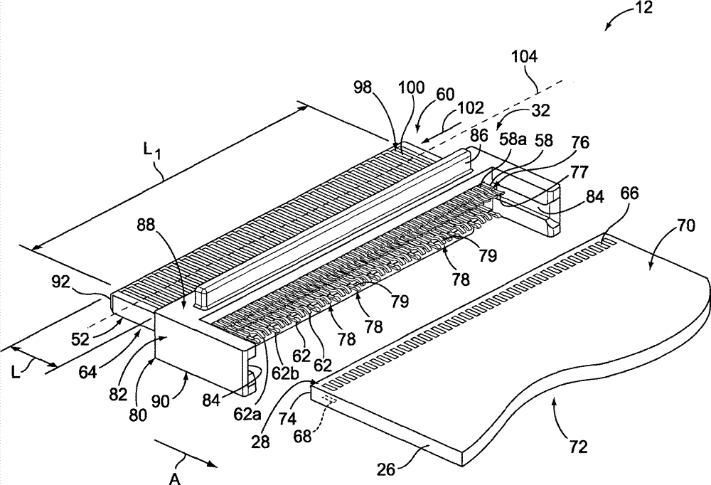
图4是从与图3不同的角度观察得到的图3所示的跨装式连接器的透视图;Fig. 4 is a perspective view of the straddle-mounted connector shown in Fig. 3 observed from a different angle from Fig. 3;

图5是图3和4所示的跨装式连接器的剖视图;Figure 5 is a cross-sectional view of the straddle connector shown in Figures 3 and 4;

图6是图3-5所示的跨装式连接器的部分分解透视图;Figure 6 is a partially exploded perspective view of the straddle connector shown in Figures 3-5;

图7是示出了图3-6所示的跨装式连接器的一排电触头的示例性实施例和接地板的示例性实施例的透视图;7 is a perspective view illustrating an exemplary embodiment of a row of electrical contacts and an exemplary embodiment of a ground plate of the straddle-mount connector shown in FIGS. 3-6;

图8是跨装式连接器的的另一示例性实施例的透视图;Figure 8 is a perspective view of another exemplary embodiment of a straddle connector;

图9是从与图8不同的角度观察得到的图8所示的跨装式连接器的另一透视图;Fig. 9 is another perspective view of the straddle-mounted connector shown in Fig. 8 observed from a different angle from Fig. 8;

图10是示出了一排电触头的示例性实施例的一部分以及接地板的示例性实施例的一部分的透视图;10 is a perspective view showing a portion of an exemplary embodiment of a row of electrical contacts and a portion of an exemplary embodiment of a ground plate;

图11是示出了图10所示的接地板的一侧的透视图;FIG. 11 is a perspective view showing one side of the ground plate shown in FIG. 10;

图12是跨装式连接器的另一示例性实施例的透视图;Figure 12 is a perspective view of another exemplary embodiment of a straddle connector;

图13是示出了图12所示的跨装式连接器的一排电触头的示例性实施例的透视图;13 is a perspective view showing an exemplary embodiment of a row of electrical contacts of the straddle connector shown in FIG. 12;

图14是图1所示的收发器组件的插座连接器的示例性实施例的透视图;14 is a perspective view of an exemplary embodiment of a receptacle connector of the transceiver assembly shown in FIG. 1;

图15是图14所示的插座连接器的一部分的透视图,其中示出了一排电触头的示例性实施例;15 is a perspective view of a portion of the receptacle connector shown in FIG. 14 showing an exemplary embodiment of a row of electrical contacts;

图16是图14和15所示的插座连接器的一部分的部分分解透视图。FIG. 16 is a partially exploded perspective view of a portion of the receptacle connector shown in FIGS. 14 and 15 .

具体实施方式Detailed ways

图1是收发器组件10的示例性实施例的一部分的透视图。在该示例性实施例中,收发器组件10尤其是适于高速传输数据信号,如SFP+标准要求的至少10吉比特每秒(Gbps)的数据传输速率。例如,在一些实施例中,收发器组件10适于以至少28Gbps的数据传输速率来传输数据信号。此外,以及例如,在一些实施例中,收发器组件10适于以在大约20Gbps至大约30Gbps之间的数据传输速率来传输数据信号。然而,应当理解的是,这里描述和/或示出的本发明的好处和优点可同样地产生于其它数据传输速率以及各种系统和标准上。换句话说,这里描述和/或示出的本发明的并不限于这里示出和描述的10Gbps或更高的数据传输速率、任意的标准、或典型类型的收发器组件。FIG. 1 is a perspective view of a portion of an exemplary embodiment of a transceiver assembly 10 . In the exemplary embodiment, transceiver assembly 10 is particularly adapted to transmit data signals at high speeds, such as the data transmission rates of at least 10 gigabits per second (Gbps) required by the SFP+ standard. For example, in some embodiments, transceiver assembly 10 is adapted to transmit data signals at a data transmission rate of at least 28 Gbps. Additionally, and for example, in some embodiments, transceiver assembly 10 is adapted to transmit data signals at a data transmission rate of between about 20 Gbps to about 30 Gbps. It should be understood, however, that the benefits and advantages of the present invention described and/or illustrated herein may equally arise for other data transmission rates and various systems and standards. In other words, the invention described and/or illustrated herein is not limited to data transfer rates of 10 Gbps or higher, any standard, or typical types of transceiver components illustrated and described herein.

收发器组件10包括可插拔模块12,其配置为可插拔地插入安装在主电路板16上的插座组件14内。主电路板16可安装在主系统(未示出)内,例如但不限于路由器、服务器、计算机等。该主系统典型地包括具有前框板18的导电底板,该前框板18包括大致与插座组件14对齐地延伸穿过其的开口20。插座组件14可选地电连接到前框板18。The transceiver assembly 10 includes a pluggable module 12 configured to be pluggably inserted into a socket assembly 14 mounted on a main circuit board 16 . The main circuit board 16 may be mounted within a host system (not shown), such as, but not limited to, a router, server, computer, or the like. The host system typically includes a conductive chassis having a front bezel 18 including an opening 20 extending therethrough generally aligned with the receptacle assembly 14 . The receptacle assembly 14 is optionally electrically connected to the bezel 18 .

可插拔模块12配置为插入到插座组件14内。具体地,可插拔模块12穿过前框板开口20而插入插座组件14内,从而使得可插拔模块12的前端部22从插座组件14向外延伸。可插拔模块12包括壳体24,其形成用于设置在壳体24内的电路板26(图2和3)的保护外壳。电路板26承载以已知方式实现收发器功能的电路、迹线、路径、器件等。电路板26的边缘28(图2和3)在壳体24的后端部30处暴露出。在示例性实施例中,连接器32(图2-6)安装到电路板26并穿过壳体24的后端部30而暴露出,用于插入到插座组件14的插座连接器34中,如下将要描述的。连接器32在图1中未示出。与连接器32可替换的,可插拔模块12的电路板26可直接地与插座连接器34相配合。换句话说,在一些可替换实施例中,可插拔模块12的电路板26的边缘28被接收在插座连接器34的插座50内,从而将可插拔模块12电连接到插座连接器34。可插拔模块12、电路板26、和/或连接器32在这里可被称为“配合连接器”。The pluggable module 12 is configured to be plugged into a socket assembly 14 . Specifically, the pluggable module 12 is inserted into the socket assembly 14 through the front bezel opening 20 such that the front end 22 of the pluggable module 12 extends outward from the socket assembly 14 . The pluggable module 12 includes a housing 24 that forms a protective enclosure for a circuit board 26 ( FIGS. 2 and 3 ) disposed within the housing 24 . The circuit board 26 carries circuits, traces, paths, devices, etc. that implement transceiver functionality in a known manner. Edge 28 ( FIGS. 2 and 3 ) of circuit board 26 is exposed at rear end 30 of housing 24 . In the exemplary embodiment, a connector 32 ( FIGS. 2-6 ) is mounted to the circuit board 26 and is exposed through the rear end 30 of the housing 24 for insertion into the receptacle connector 34 of the receptacle assembly 14 , as will be described below. Connector 32 is not shown in FIG. 1 . As an alternative to connector 32 , circuit board 26 of pluggable module 12 may directly mate with receptacle connector 34 . In other words, in some alternative embodiments, the edge 28 of the circuit board 26 of the pluggable module 12 is received within the receptacle 50 of the receptacle connector 34, thereby electrically connecting the pluggable module 12 to the receptacle connector 34 . Pluggable modules 12, circuit boards 26, and/or connectors 32 may be referred to herein as "mating connectors."

一般地,可插拔模块12和插座组件14可用于在主系统与电气和/或光学信号之间需要接口的任意应用场合中。可插拔模块12经由插座组件14的插座连接器34通过插座组件14而连接到主系统,该插座组件14设置在插座引导框架36内,该框架也被称为罩。如图1所示,引导框架36包括具有前部开口40的前端部38,该前部开口40开口到引导框架36的内部空间42。插座连接器34在引导框架36的后部44处设置在内部空间42内。引导框架36的内部空间42配置为将可插拔模块12接收于其内,并与插座连接器34形成电连接。In general, pluggable module 12 and socket assembly 14 may be used in any application requiring an interface between a host system and electrical and/or optical signals. The pluggable module 12 is connected to the host system through the socket assembly 14 via the socket connector 34 of the socket assembly 14, which is disposed within a socket guide frame 36, which frame is also referred to as a shroud. As shown in FIG. 1 , the guide frame 36 includes a front end portion 38 having a front opening 40 that opens to an interior space 42 of the guide frame 36 . The receptacle connector 34 is disposed within the interior space 42 at the rear 44 of the guide frame 36 . The interior space 42 of the guide frame 36 is configured to receive the pluggable module 12 therein and form an electrical connection with the receptacle connector 34 .

可插拔模块12在前端部22处通过连接器接口46而连接到一个或多个光缆(未示出)和/或一个或多个电缆(未示出)。可选地,连接器接口46包括一机构,其与光纤或电缆协同作用,从而将光纤或电缆固定到可插拔模块12。合适的连接器接口46是公知的并包括用于由Tyco ElectronicsCorparation(Harrisburg,Pa.)提供的LC型光纤连接器和MTP/MPO型光纤连接器的适配器。The pluggable module 12 is connected to one or more fiber optic cables (not shown) and/or one or more electrical cables (not shown) at the front end 22 through a connector interface 46 . Optionally, the connector interface 46 includes a mechanism that cooperates with the optical fiber or cable to secure the optical fiber or cable to the pluggable module 12 . Suitable connector interfaces 46 are well known and include adapters for LC-type fiber optic connectors and MTP/MPO-type fiber optic connectors supplied by Tyco Electronics Corporation (Harrisburg, Pa.).

图2是收发器组件10的剖视图,其中示出了与插座组件14相配合的可插拔模块12。插座连接器34安装在主电路板16上。插座连接器34包括具有插座50的介电壳体本体48。跨装式连接器32安装到电路板26的边缘28并电连接到电路板26,如下面将要详细描述的。FIG. 2 is a cross-sectional view of the transceiver assembly 10 showing the pluggable module 12 mated with the receptacle assembly 14 . The socket connector 34 is mounted on the main circuit board 16 . The receptacle connector 34 includes a dielectric housing body 48 having a receptacle 50 . The straddle mount connector 32 is mounted to the edge 28 of the circuit board 26 and is electrically connected to the circuit board 26 as will be described in detail below.

插座连接器34的插座50将跨装式连接器32的插头52接收于其内。插座连接器34包括电触头54和电触头56。电触头54在插座50内延伸,并接合位于跨装式连接器32的插头52的一侧部60上的对应电触头58(图3和5)。电触头56也在插座50内延伸,但是电触头56接合插头52的与侧部60相反的侧部64上的对应电触头62(图3-7)。跨装式连接器32的电触头58和62电连接到分别位于电路板26的相对侧70和72上的对应导电触头焊盘66和68(图3),从而在电路板26与主电路板16之间建立电连接。电触头54在这里可被称为“辅助触头”。触头焊盘66和/或68在这里可被称为“配合触头”和/或“触头”。插头52的每个侧部60和64在这里可被称为“第一侧部”和/或“第二侧部”。The receptacle 50 of the receptacle connector 34 receives the plug 52 of the straddle connector 32 therein. The receptacle connector 34 includes electrical contacts 54 and 56 . The electrical contacts 54 extend within the receptacle 50 and engage corresponding electrical contacts 58 on one side 60 of the plug 52 of the straddle connector 32 ( FIGS. 3 and 5 ). Electrical contacts 56 also extend within receptacle 50 , but engage corresponding electrical contacts 62 on a side 64 of plug 52 opposite side 60 ( FIGS. 3-7 ). The electrical contacts 58 and 62 of the straddle connector 32 are electrically connected to corresponding conductive contact pads 66 and 68 ( FIG. 3 ) on opposite sides 70 and 72 of the circuit board 26, respectively, so that Electrical connections are established between the circuit boards 16 . The electrical contacts 54 may be referred to herein as "auxiliary contacts." Contact pads 66 and/or 68 may be referred to herein as "mating contacts" and/or "contacts." Each side 60 and 64 of plug 52 may be referred to herein as a "first side" and/or a "second side."

图3是可插拔模块12的一部分的分解视图,其中示出了电路板26和跨装式连接器32。电路板26包括相对的侧部70和72以及边缘28。边缘28包括边缘表面74和靠近边缘表面74延伸的侧部70和72的那些部分。触头焊盘66沿着边缘28设置在电路板26的侧部70上。触头焊盘68沿着边缘28设置在侧部72上。FIG. 3 is an exploded view of a portion of pluggable module 12 showing circuit board 26 and straddle mount connector 32 . Circuit board 26 includes opposing sides 70 and 72 and edge 28 . Edge 28 includes edge surface 74 and those portions of sides 70 and 72 that extend proximate edge surface 74 . The contact pads 66 are disposed on the side 70 of the circuit board 26 along the edge 28 . The contact pads 68 are disposed on the side 72 along the edge 28 .

跨装式连接器32配置为安装到电路板26的边缘28。例如,跨装式连接器32在装载方向A上被装载到边缘28。跨装式连接器32的电触头58包括具有安装接口77的安装部分76,该安装接口77接合位于电路板26的侧部70上的对应触头焊盘66。电触头62包括具有安装接口79的安装部分78,该安装接口79接合位于电路板26的侧部72上的对应触头焊盘68。电触头58和62的安装部分76和78分别地跨骑在电路板26的边缘28之间。The straddle mount connector 32 is configured to mount to the edge 28 of the circuit board 26 . For example, the straddle mount connector 32 is loaded in the loading direction A to the edge 28 . The electrical contacts 58 of the straddle mount connector 32 include mounting portions 76 having mounting interfaces 77 that engage corresponding contact pads 66 on the side 70 of the circuit board 26 . The electrical contacts 62 include mounting portions 78 having mounting interfaces 79 that engage corresponding contact pads 68 on the side 72 of the circuit board 26 . Mounting portions 76 and 78 of electrical contacts 58 and 62 , respectively, straddle between edges 28 of circuit board 26 .

跨装式连接器32包括具有基部82和插头52的介电连接器本体80,该插头52从基部82向外延伸。基部82配置为耦接到电路板26的边缘28。在示例性实施例中,基部82将电路板26的边缘28的一部分接收到基部82的狭缝84中,从而通过干涉配合将电路板26耦接到基部82。然而,基部82可采用任意其它的结构、装置、连接类型和/或等而耦接到电路板26的边缘28,例如但不限于采用锁扣式连接,采用闩锁件、螺纹状和其它固定件,粘结剂、和/或类似其它连接方式。可选地,肋部86可从基部82的侧部88和/或侧部90延伸,以与可插拔模块12(图1和2)的壳体24(图1)相连接。例如,当可插拔模块12被组装时,肋部86可被容留在可插拔模块12的壳体24内,从而将跨装式连接器32在其后端部30(图1)处相对于壳体24而固定。The straddle connector 32 includes a dielectric connector body 80 having a base 82 and a plug 52 extending outwardly from the base 82 . The base 82 is configured to couple to the edge 28 of the circuit board 26 . In the exemplary embodiment, base 82 receives a portion of edge 28 of circuit board 26 into slot 84 of base 82 , thereby coupling circuit board 26 to base 82 by an interference fit. However, the base 82 may be coupled to the edge 28 of the circuit board 26 using any other structure, device, connection type, and/or the like, such as, but not limited to, snap-fit connections, latches, threaded and other fastening components, adhesives, and/or similar other means of attachment. Optionally, ribs 86 may extend from side 88 and/or side 90 of base 82 for coupling with housing 24 ( FIG. 1 ) of pluggable module 12 ( FIGS. 1 and 2 ). For example, when the pluggable module 12 is assembled, the ribs 86 may be received within the housing 24 of the pluggable module 12, thereby opposing the straddle connector 32 at its rear end 30 ( FIG. 1 ). fixed on the housing 24.

如上所述,插头52配置为被接收在插座连接器34(图1,2和14-16)的插座50(图2和14)内。插头52包括相对的侧部60和64。插头52从基部82到插头52的端部表面92向外延伸一长度L。如以下将要描述的,插头52包括将接地板96(图5-7)接收于其内的板空腔94(图4和5)。As noted above, the plug 52 is configured to be received within the receptacle 50 (Figs. 2 and 14) of the receptacle connector 34 (Figs. 1, 2 and 14-16). Plug 52 includes opposing sides 60 and 64 . Plug 52 extends outwardly a length L from base 82 to end surface 92 of plug 52 . As will be described below, the plug 52 includes a plate cavity 94 ( FIGS. 4 and 5 ) that receives a ground plate 96 ( FIGS. 5-7 ) therein.

跨装式连接器32的电触头58和62由连接器本体80保持。电触头62包括信号触头62a和接地触头62b。信号触头62a配置为传导电数据信号,同时接地触头62b配置为电连接到地。可选地,电触头62包括一个或多个配置为传导电力的电力触头。在示例性实施例中,跨装式连接器32的电触头58包括信号触头58a,但是并不包括接地触头。然而,在一些可替换实施例中,电触头58包括接地触头。可选地,电触头58包括一个或多个配置为传导电力的电力触头。信号触头58a和62a中的每一个在这里可被称为“第一”和/或“第二”信号触头。The electrical contacts 58 and 62 of the straddle connector 32 are retained by the connector body 80 . The electrical contacts 62 include signal contacts 62a and ground contacts 62b. The signal contacts 62a are configured to conduct electrical data signals, while the ground contacts 62b are configured to be electrically connected to ground. Optionally, electrical contacts 62 include one or more power contacts configured to conduct electrical power. In the exemplary embodiment, the electrical contacts 58 of the straddle connector 32 include signal contacts 58a, but do not include ground contacts. However, in some alternative embodiments, the electrical contacts 58 include ground contacts. Optionally, electrical contacts 58 include one or more power contacts configured to conduct electrical power. Each of the signal contacts 58a and 62a may be referred to herein as a "first" and/or "second" signal contact.

跨装式连接器32的电触头58包括具有配合接口100的配合部分98,电触头58在该配合接口100处接合插座连接器34的对应电触头54(图2和14)。电触头58的配合接口100与对应电触头54之间的接合使在连接器32与34之间形成电连接。电触头58的配合部分98设置成一排102,该排102沿着插头52的侧部60延伸一长度L1。排102沿着排轴线104延伸该长度L1。电触头58在这里可被称为“第一组”和/或“第二组”。该排102在这里可被称为“第一排”和/或“第二排”。每个配合部分98在这里可被称为“接地配合部分”。The electrical contacts 58 of the straddle connector 32 include mating portions 98 having mating interfaces 100 where the electrical contacts 58 engage corresponding electrical contacts 54 of the receptacle connector 34 ( FIGS. 2 and 14 ). Engagement between the mating interface 100 of the electrical contact 58 and the corresponding electrical contact 54 forms an electrical connection between the connectors 32 and 34 . The mating portions 98 of the electrical contacts 58 are arranged in a row 102 extending a length L 1 along the side 60 of the plug 52 . The row 102 extends the length L 1 along the row axis 104 . The electrical contacts 58 may be referred to herein as a "first set" and/or a "second set." The row 102 may be referred to herein as a "first row" and/or a "second row." Each mating portion 98 may be referred to herein as a "ground mating portion."

图4是从与图3不同的角度观察得到的跨装式连接器32的透视图。更具体地,图3分别示出了插头52和基部82的侧部60和88,同时图4示出了插头52和基部82各自的侧部64和90。跨装式连接器32的电触头62包括具有配合接口108的配合部分106,电触头62在该配合接口108处接合插座连接器34(图1,2和14-16)的对应电触头56(图2,15和16)。电触头62的配合部分108与对应电触头56之间的接合使在连接器32与34之间建立电连接。电触头62的配合部分106设置成一排110,该排110沿着插头52的侧部64延伸一长度L2。排110沿着排轴线112延伸该长度L2。电触头62在这里可被称为“第一组”和/或“第二组”。排110在这里可被称为“第一排”和/或“第二排”。FIG. 4 is a perspective view of the straddle-mount connector 32 viewed from a different angle from FIG. 3 . More specifically, FIG. 3 shows sides 60 and 88 of plug 52 and base 82 , respectively, while FIG. 4 shows sides 64 and 90 of plug 52 and base 82 , respectively. The electrical contacts 62 of the straddle connector 32 include mating portions 106 having mating interfaces 108 at which the electrical contacts 62 engage corresponding electrical contacts of the receptacle connector 34 ( FIGS. 1 , 2 and 14-16 ). Head 56 (Figures 2, 15 and 16). Engagement between the mating portion 108 of the electrical contact 62 and the corresponding electrical contact 56 establishes an electrical connection between the connectors 32 and 34 . The mating portions 106 of the electrical contacts 62 are arranged in a row 110 extending a length L 2 along the side 64 of the plug 52 . Row 110 extends along row axis 112 the length L 2 . The electrical contacts 62 may be referred to herein as a "first set" and/or a "second set." Rows 110 may be referred to herein as "first row" and/or "second row."

图5是跨装式连接器32的剖视图。图5示出了位于电触头62的排110中的信号触头62a和位于电触头58的排102中的信号触头58a。信号触头58a和62a各自包括牢固地耦接到连接器本体80的基部82的触头基部114a和116a。在示例性实施例中,触头基部114a和116a分别包括一个或多个保持凸起118a和120a,它们接合基部82的一部分以与其形成干涉,从而将触头58a和62a相对于连接器本体80保持到位。另外地或者可替换地,触头58a和/或62a可采用任意其它的结构、装置、连接类型和/或等而牢固地耦接到连接器本体80,例如但不限于锁扣式连接、采用闩锁件、螺纹状或其它紧固件、粘结剂和/或类似其它连接方式。FIG. 5 is a cross-sectional view of the straddle-mount connector 32 . FIG. 5 shows signal contacts 62 a in row 110 of electrical contacts 62 and signal contacts 58 a in row 102 of electrical contacts 58 . The signal contacts 58 a and 62 a each include a contact base 114 a and 116 a that is securely coupled to the base 82 of the connector body 80 . In an exemplary embodiment, contact bases 114a and 116a include one or more retention projections 118a and 120a, respectively, that engage a portion of base 82 to interfere therewith to hold contacts 58a and 62a relative to connector body 80. Hold in place. Additionally or alternatively, contacts 58a and/or 62a may be securely coupled to connector body 80 using any other structure, device, connection type, and/or the like, such as, but not limited to, a snap-fit connection, using Latches, threaded or other fasteners, adhesives, and/or similar other means of attachment.

信号触头58a和62a的配合部分98a和106a分别地沿着插头52的侧部60和64从各自的触头基部114a和116a向外延伸各自的长度L3和L4。配合部分98a和106a的配合接口100a和108a分别地用于与插座连接器34(图1,2和14-16)的各个电触头54(图2和14)和56(图2,15和16)相配合。每个配合部分98a和116a在这里可被称为“信号配合部分”。The mating portions 98a and 106a of the signal contacts 58a and 62a extend respective lengths L 3 and L 4 outward from the respective contact bases 114a and 116a along the sides 60 and 64 of the plug 52 , respectively. The mating interfaces 100a and 108a of the mating portions 98a and 106a, respectively, are used with the respective electrical contacts 54 (Figs. 2 and 14) and 56 (Figs. 2, 15 and 14-16) of the receptacle connector 34 (Figs. 16) Match. Each mating portion 98a and 116a may be referred to herein as a "signal mating portion."

信号触头58a和62a的安装部分76a和78a分别地在与配合部分98a和106a相反的方向上从各自的触头基部114a和116a向外延伸。安装部分76a和78a包括各自的安装接口77a和79a,它们用于与分别位于电路板26(图2和3)的侧部70和72上的各自触头焊盘66和68(图3)相接合。空间122设置在安装部分76a和78a之间,以用于接收电路板26的边缘28(图2和3)。换句话说,信号触头58a和62a的安装部分76a和78a分别地跨骑在电路板26的边缘28之间。可选地,安装接口77a和/或79a焊接到各自的触头焊盘66和68。在可替换实施例中,其它的安装方式也是可以的。可选地,以及可从图5中看出,信号触头58a和62a被如此地设置,从而使得信号触头58a在插头52的相对侧部60和64上与信号触头62a对齐。Mounting portions 76a and 78a of signal contacts 58a and 62a respectively extend outwardly from respective contact bases 114a and 116a in a direction opposite mating portions 98a and 106a. Mounting portions 76a and 78a include respective mounting interfaces 77a and 79a for interfacing with respective contact pads 66 and 68 (FIG. 3) on sides 70 and 72, respectively, of circuit board 26 (FIGS. 2 and 3). join. Space 122 is provided between mounting portions 76a and 78a for receiving edge 28 of circuit board 26 (FIGS. 2 and 3). In other words, the mounting portions 76a and 78a of the signal contacts 58a and 62a, respectively, straddle between the edges 28 of the circuit board 26 . Optionally, mounting interfaces 77a and/or 79a are soldered to respective contact pads 66 and 68 . In alternative embodiments, other mounting arrangements are possible. Optionally, and as can be seen from FIG. 5 , signal contacts 58 a and 62 a are positioned such that signal contacts 58 a are aligned with signal contacts 62 a on opposite sides 60 and 64 of plug 52 .

如上面简要描述的,插头52包括将接地板96接收于其内的板空腔94。板空腔94在侧部60和64之间在插头52内延伸。板空腔94穿过插头52朝着插头52的端部表面92延伸。板空腔94可选地延伸穿过端部表面92。图5示出了接收于板空腔94内的接地板96。当安装在板空腔94内时,接地板96沿着各个排102和110的长度L1(图3)和L2(图4)在各个触头58和62的排102和110之间延伸。接地板96也分别地沿着信号触头58a和62a的配合部分98a和106a的长度L3和L4在排102和110之间延伸。可选地,以及可从图5中看出,接地板96分别地沿着信号触头58a和62a的配合部分98a和106a的整个长度L3和L4在排102和110之间延伸。当接地板96被安装在板空腔94内时,插头52具有分层结构,其包括介电材料底层101、由接地板96限定的中间层105、以及介电材料顶层103。底层101包括插头52的侧部60,同时顶层103包括插头52的侧部64。As briefly described above, the plug 52 includes a plate cavity 94 that receives a ground plate 96 therein. A board cavity 94 extends within the plug 52 between the sides 60 and 64 . The board cavity 94 extends through the plug 52 toward the end surface 92 of the plug 52 . A plate cavity 94 optionally extends through the end surface 92 . FIG. 5 shows ground plate 96 received within plate cavity 94 . When mounted within the board cavity 94, the ground plate 96 extends between the rows 102 and 110 of the respective rows 102 and 110 along the lengths L1 (FIG. 3) and L2 (FIG. 4) of the respective rows 102 and 110. . Ground plate 96 also extends between rows 102 and 110 along lengths L3 and L4 of mating portions 98a and 106a of signal contacts 58a and 62a, respectively. Optionally, and as can be seen in FIG. 5 , ground plate 96 extends between rows 102 and 110 along the entire lengths L 3 and L 4 of mating portions 98 a and 106 a of signal contacts 58 a and 62 a , respectively. When ground plate 96 is installed within board cavity 94 , plug 52 has a layered structure that includes a bottom layer 101 of dielectric material, a middle layer 105 defined by ground plate 96 , and a top layer 103 of dielectric material. Bottom layer 101 includes side 60 of plug 52 , while top layer 103 includes side 64 of plug 52 .

图6是跨装式连接器32的部分分解透视图,其示出接地板96和电触头62的接地触头62b。图6示出电触头62的排110中的信号触头62a沿插头52的侧部64设置。然而,为清楚起见,已经从插头52的侧部64分解示出电触头62的排110中的接地触头62b。此外,为清楚起见,已经从插头52的外部分解示出接地板96。FIG. 6 is a partially exploded perspective view of the straddle mount connector 32 showing the ground plate 96 and the ground contacts 62b of the electrical contacts 62 . FIG. 6 shows that the signal contacts 62 a in the row 110 of electrical contacts 62 are disposed along the side 64 of the plug 52 . However, the ground contacts 62b in the rows 110 of the electrical contacts 62 have been shown exploded from the side 64 of the plug 52 for clarity. Additionally, the ground plate 96 has been shown exploded from the exterior of the plug 52 for clarity.

接地触头62b包括触头基部116b,其可选地牢固耦接到连接器本体80的基部82。在示例性实施例中,触头基部116b包括一个或多个保持凸起120b,其接合基部82的一部分从而与其之间形成干涉,以将接地触头62b相对于连接器本体80保持到位。另外地或者可替换地,接地触头62b可采用任意其它地结构、装置、连接类型和/或等牢固地耦接到连接器本体80,例如但不限于采用锁扣式连接、采用闩锁件、螺纹状或其它紧固件、粘结剂和/或类似其它连接方式。The ground contact 62b includes a contact base 116b that is optionally securely coupled to the base 82 of the connector body 80 . In an exemplary embodiment, the contact base 116b includes one or more retention projections 120b that engage a portion of the base 82 to interfere therewith to retain the ground contact 62b in place relative to the connector body 80 . Additionally or alternatively, the ground contact 62b may be securely coupled to the connector body 80 using any other structure, device, connection type, and/or the like, such as, but not limited to, a snap-fit connection, a latch , threaded or other fasteners, adhesives, and/or similar other means of connection.

接地触头62b的配合部分106b从触头基部116b向外延伸长度L5。如图4所示,配合部分106b沿着插头52的侧部64延伸。配合部分106b的配合接口108b用于与插座连接器34(图1,2和14-16)的对应电触头56(图2,15和16)相配合。每个配合部分106b在这里可被称为“接地配合部分”。The mating portion 106b of the ground contact 62b extends outwardly from the contact base 116b by a length L 5 . As shown in FIG. 4 , the mating portion 106 b extends along the side 64 of the plug 52 . The mating interface 108b of the mating portion 106b is adapted to mate with the corresponding electrical contact 56 (Figs. 2, 15 and 16) of the receptacle connector 34 (Figs. 1, 2 and 14-16). Each mating portion 106b may be referred to herein as a "ground mating portion."

接地触头62b可选地与接地板96接合并电连接到接地板96,从而使得接地板96和接地触头62b电气地共位。例如,接地触头62b的配合部分106b可选地延伸穿过开口124,该开口124延伸穿过插头52的侧部64并与板空腔94(图4和5)流体式地连通。开口124使得配合部分106b能够接合并且从而电连接到接地板96。可选地,触头基部116b包括用于将接地触头62b安装到接地板96的保持凸起126。The ground contacts 62b are optionally engaged with and electrically connected to the ground plate 96 such that the ground plate 96 and the ground contacts 62b are electrically co-located. For example, the mating portion 106b of the ground contact 62b optionally extends through an opening 124 that extends through the side 64 of the plug 52 and is in fluid communication with the board cavity 94 ( FIGS. 4 and 5 ). The opening 124 enables the mating portion 106b to engage and thereby be electrically connected to the ground plate 96 . Optionally, the contact base 116b includes retention projections 126 for mounting the ground contacts 62b to the ground plate 96 .

接地触头62b的安装部分78b在与配合部分106b相反的方向上从触头基部116b向外延伸。安装部分78b包括用于与位于电路板26的侧部72(图2和3)上的对应触头焊盘68(图3)接合的安装接口79b。可选地,安装接口79b焊接到对应的触头焊盘68。其它的安装方式在可替换实施例中也是可以的。The mounting portion 78b of the ground contact 62b extends outwardly from the contact base 116b in a direction opposite to the mating portion 106b. The mounting portion 78b includes a mounting interface 79b for engaging corresponding contact pads 68 ( FIG. 3 ) on the side 72 ( FIGS. 2 and 3 ) of the circuit board 26 . Optionally, the mounting interface 79b is soldered to the corresponding contact pad 68 . Other mounting arrangements are also possible in alternative embodiments.

接地板96从端部128到相对端部130延伸长度L6。接地板96从端部132到相对端部134延伸宽度W。在示例性实施例中,以及如可在图6中看出的,接地板96大致是平面状的。更具体地,接地板96具有限定在端部128和130之间以及在端部132和134之间的大致平面形状。接地板96可选地包括多个狭缝136,其接收接地触头62b的保持凸起126,并通过干涉配合而将接地触头62b安装到接地板96。另外地或者可替换地,其它的结构、装置、连接类型和/或等可用于将接地触头62b安装到接地板96,例如但不限于采用锁扣式连接、采用闩锁件、螺纹状或其它紧固件、粘结剂和/或类似其它结构。Ground plate 96 extends a length L 6 from end 128 to opposite end 130 . The ground plate 96 extends a width W from an end 132 to an opposite end 134 . In the exemplary embodiment, and as can be seen in FIG. 6 , ground plate 96 is generally planar. More specifically, ground plate 96 has a generally planar shape defined between ends 128 and 130 and between ends 132 and 134 . The ground plate 96 optionally includes a plurality of slots 136 that receive the retention protrusions 126 of the ground contacts 62b and mount the ground contacts 62b to the ground plate 96 by an interference fit. Additionally or alternatively, other structures, devices, connection types, and/or the like may be used to mount the ground contacts 62b to the ground plate 96, such as, but not limited to, snap-fit connections, latches, threaded or Other fasteners, adhesives and/or similar other structures.

再次参考图4,接地板96用虚线标识出。当安装在板空腔94内时,接地板96分别沿着各个排102和110的长度L1(图3)和L2在电触头58和62的排102和排110之间延伸。更具体地,接地板96的长度L6(图6)分别沿着各个排102和110的长度L1和L2在电触头58和62的排102和110之间延伸。可选地,接地板96的长度L6沿着相应排102和110的整个长度L1和L2在排102和110之间延伸。Referring again to FIG. 4 , ground plate 96 is identified with dashed lines. When mounted within board cavity 94 , ground plate 96 extends between row 102 and row 110 of electrical contacts 58 and 62 along lengths L 1 ( FIG. 3 ) and L 2 of respective rows 102 and 110 , respectively. More specifically, the length L 6 ( FIG. 6 ) of the ground plate 96 extends between the rows 102 and 110 of the electrical contacts 58 and 62 along the lengths L 1 and L 2 of the respective rows 102 and 110 , respectively. Optionally, the length L6 of the ground plate 96 extends between the rows 102 and 110 along the entire lengths L1 and L2 of the respective rows 102 and 110 .

接地板96也分别沿着各个部分98和106的长度在电触头58(图3和5),62的排102,110之间延伸。更具体地,接地板96的宽度W沿着分别位于排110中的信号和接地触头62a和62b的各自配合部分106a和106b的长度L4和L5分别地在电触头58和62的排102和110之间延伸。可选地,接地板96的宽度W沿着相应配合部分106a和106b的整个长度L4和L5在排102和110之间延伸。接地板96的宽度W也沿着排110中的电触头58的配合部分98的长度L3分别地在电触头58和62的排102和110之间延伸。可选地,接地板96的宽度W沿着配合部分98的整个长度L3在排102和110之间延伸。The ground plate 96 also extends between the rows 102, 110 of the electrical contacts 58 (Figs. 3 and 5), 62 along the length of the respective sections 98 and 106, respectively. More specifically, the width W of the ground plate 96 is along the lengths L4 and L5 of the respective mating portions 106a and 106b of the signal and ground contacts 62a and 62b, respectively, located in the row 110 at the width of the electrical contacts 58 and 62, respectively. Rows 102 and 110 extend between. Optionally, the width W of the ground plate 96 extends between the rows 102 and 110 along the entire lengths L4 and L5 of the respective mating portions 106a and 106b. Width W of ground plate 96 also extends between rows 102 and 110 of electrical contacts 58 and 62 , respectively, along length L 3 of mating portion 98 of electrical contacts 58 in row 110 . Optionally, the width W of ground plate 96 extends between rows 102 and 110 along the entire length L 3 of mating portion 98 .

图7是示出了电触头62和接地板96的排110的透视图。如可从图7中可以看到的,电触头62的接地触头62b安装到接地板96,从而使得接地触头62接合并电连接到接地板96。可替换的,一个或多个接地触头62b未安装到和/或未接合于接地板96。FIG. 7 is a perspective view showing the row 110 of the electrical contacts 62 and the ground plate 96 . As can be seen from FIG. 7 , the ground contact 62 b of the electrical contact 62 is mounted to the ground plate 96 such that the ground contact 62 engages and is electrically connected to the ground plate 96 . Alternatively, one or more ground contacts 62 b are not mounted to and/or bonded to ground plate 96 .

在示例性实施例中,排110中的信号触头62a设置成差分对62A。可替换地,排110中的一个或多个信号触头62a不与排110中的任意其它信号触头62a设置成差分对。此外,排110中的一个或多个信号触头62a可与排102(图4和5)中的信号触头58a(图3和5)设置成差分对。In the exemplary embodiment, the signal contacts 62a in the row 110 are arranged in a differential pair 62A. Alternatively, one or more signal contacts 62a in row 110 are not arranged in a differential pair with any other signal contacts 62a in row 110 . Additionally, one or more signal contacts 62a in row 110 may be arranged as a differential pair with signal contacts 58a ( FIGS. 3 and 5 ) in row 102 ( FIGS. 4 and 5 ).

接地触头62b设置在信号触头62a的差分对62A之间。更具体地,接地触头62b的配合部分106b在信号触头62a的相邻差分对62A的配合部分106a之间设置成排110。接地触头62b的配合部分106b在相邻信号触头62a的配合部分106a之间提供电气屏蔽。在示例性实施例中,以及如图7所示,接地触头62b在信号触头62a的相邻差分对62A之间提供电气屏蔽。可选地,电触头62的排110包括位于排110的端部138处和/或位于相对的端部141处的接地触头62b。尽管仅示出了单个接地触头62b在相邻差分对62A之间延伸,但是也可以是任意数量的接地触头62b在相邻差分对62A之间延伸。Ground contacts 62b are disposed between differential pairs 62A of signal contacts 62a. More specifically, the mating portions 106b of the ground contacts 62b are arranged in a row 110 between the mating portions 106a of adjacent differential pairs 62A of the signal contacts 62a. The mating portion 106b of the ground contact 62b provides electrical shielding between the mating portion 106a of the adjacent signal contact 62a. In an exemplary embodiment, and as shown in FIG. 7 , ground contacts 62 b provide electrical shielding between adjacent differential pairs 62A of signal contacts 62 a. Optionally, row 110 of electrical contacts 62 includes ground contact 62b at end 138 of row 110 and/or at an opposite end 141 . Although only a single ground contact 62b is shown extending between adjacent differential pairs 62A, any number of ground contacts 62b may extend between adjacent differential pairs 62A.

每个电触头62的配合部分106包括相对的宽侧面表面140和在宽侧表面140之间延伸的相对边缘侧表面142。更具体地,信号触头62a的配合部分106a包括宽侧表面140a和边缘侧表面142a,而接地触头62b的配合部分106b包括宽侧表面140b和边缘侧表面142b。如可从图7中看出的,宽侧表面140a具有比边缘侧表面142a更大的表面面积。类似的,宽侧表面140b具有比边缘侧表面142b更大的表面面积。接地触头62b的宽侧表面140b具有比信号触头62a的边缘侧表面142a更大的表面面积。在差分对62A内,差分对62A内的一个信号触头62a的边缘侧表面142a可选地面对差分对62A中的另一信号触头62a的边缘侧表面142a。例如,差分对62A中的信号触头62a的边缘侧表面142a可选地大致彼此平行地延伸。差分对62A中的信号触头62a的配合部分106a可比至少一些已知的信号触头差分对的配合部分更加紧密地布置在一起。The mating portion 106 of each electrical contact 62 includes opposing broad side surfaces 140 and opposing edge side surfaces 142 extending between the broad side surfaces 140 . More specifically, the mating portion 106a of the signal contact 62a includes a broadside surface 140a and an edge side surface 142a, while the mating portion 106b of the ground contact 62b includes a broadside surface 140b and an edge side surface 142b. As can be seen from FIG. 7, the broad side surface 140a has a larger surface area than the edge side surface 142a. Similarly, broadside surface 140b has a larger surface area than edge side surface 142b. The broad side surfaces 140b of the ground contacts 62b have a larger surface area than the edge side surfaces 142a of the signal contacts 62a. Within differential pair 62A, edge side surface 142a of one signal contact 62a within differential pair 62A optionally faces edge side surface 142a of the other signal contact 62a in differential pair 62A. For example, edge side surfaces 142a of signal contacts 62a in differential pair 62A optionally extend generally parallel to one another. The mating portions 106a of the signal contacts 62a in the differential pair 62A may be arranged closer together than mating portions of at least some known differential pairs of signal contacts.

对于每个接地触头62b,配合部分106b的宽侧表面140b面对相邻信号触头62a的配合部分106a的对应边缘侧表面142a。例如,接地触头62ba的配合部分106b的一个宽侧表面104ba面对相邻信号触头62aa的配合部分106a的边缘侧表面142aa,同时接地触头62ba的配合部分106b的另一宽侧表面140bb面对另一相邻信号触头62ab的配合部分106a的边缘侧表面142ab。可选地,接地触头62b的边缘侧表面142b与信号触头62a的宽侧表面140a共面地延伸,如由图7中平面148标识的。For each ground contact 62b, the broadside surface 140b of the mating portion 106b faces the corresponding edge side surface 142a of the mating portion 106a of the adjacent signal contact 62a. For example, one broadside surface 104ba of the mating portion 106b of the ground contact 62ba faces the edge side surface 142aa of the mating portion 106a of the adjacent signal contact 62aa, while the other broadside surface 140bb of the mating portion 106b of the ground contact 62ba The edge side surface 142ab of the mating portion 106a facing the other adjacent signal contact 62ab. Optionally, edge side surfaces 142b of ground contacts 62b extend coplanar with broadside surfaces 140a of signal contacts 62a, as identified by plane 148 in FIG. 7 .

接地触头62b的配合部分106b可提供比至少一些已知的接地触头更大的屏蔽。此外,接地触头62b的配合部分106b可使得相邻的信号触头62a(例如信号触头62a的相邻差分对62A)能够更加紧密地设置在一起,同时提供与至少一些已知的接地触头相同量的屏蔽。The mating portion 106b of the ground contact 62b may provide greater shielding than at least some known ground contacts. In addition, the mating portion 106b of the ground contact 62b can enable adjacent signal contacts 62a (eg, adjacent differential pairs 62A of the signal contacts 62a) to be positioned closer together while providing the same advantages as at least some known ground contacts. head with the same amount of shielding.

在示例性实施例中,以及如可从图7中看出的,接地触头62b的配合部分106b的宽侧表面140b大致垂直于相邻信号触头62a的配合部分106a的宽侧表面140a延伸。例如,接地触头62b的宽侧表面140b位于平面146内,以及信号触头62a的宽侧表面140a位于平面148内。平面146大致垂直于平面148而取向。但是,接地触头62b的配合部分106b的宽侧表面140b可相对于相邻信号触头62a的配合部分106a的宽侧表面140a以任意非平行的角度延伸。In the exemplary embodiment, and as can be seen from FIG. 7, the broadside surface 140b of the mating portion 106b of the ground contact 62b extends generally perpendicular to the broadside surface 140a of the mating portion 106a of the adjacent signal contact 62a. . For example, broadside surfaces 140b of ground contacts 62b lie in plane 146 and broadside surfaces 140a of signal contacts 62a lie in plane 148 . Plane 146 is oriented generally perpendicular to plane 148 . However, the broadside surface 140b of the mating portion 106b of the ground contact 62b may extend at any non-parallel angle relative to the broadside surface 140a of the mating portion 106a of the adjacent signal contact 62a.

再次参考图3,在示例性实施例中,电触头58的排102不包括任意的接地触头。可替换地,电触头58的排102包括一个或多个接地触头。例如,电触头58的排102可包括具有配合部分的一个或多个接地触头,该配合部分具有信号触头58a(图3和5)的配合部分98a的形状和/或取向。另一例子包括为电触头58的排102提供具有配合部分的一个或多个接地触头,该配合部分具有接地触头62b(图3,4,6和7)的配合部分106b(图4,6和7)的形状和/或取向。Referring again to FIG. 3 , in the exemplary embodiment, the rows 102 of electrical contacts 58 do not include any ground contacts. Alternatively, row 102 of electrical contacts 58 includes one or more ground contacts. For example, row 102 of electrical contacts 58 may include one or more ground contacts having mating portions that have the shape and/or orientation of mating portions 98a of signal contacts 58a ( FIGS. 3 and 5 ). Another example includes providing the row 102 of electrical contacts 58 with one or more ground contacts having mating portions having mating portions 106b ( FIG. 4 ) of ground contacts 62b ( FIGS. 3 , 4 , 6 and 7 ). , 6 and 7) shape and/or orientation.

在电触头58的排102包括至少一个接地触头的一些实施例中,排102中的一个或多个接地触头可电连接到排110中的一个或多个接地触头62b,从而将电连接到一起的接地触头电气地共用。例如,排102中的接地触头可与排110中的接地触头62b相接合。此外,以及例如,排102中的接地触头可通过接地板96电连接到排110中的接地触头62b(例如两个接地触头都接合接地板96)。In some embodiments where row 102 of electrical contacts 58 includes at least one ground contact, one or more ground contacts in row 102 may be electrically connected to one or more ground contacts 62b in row 110, thereby connecting The ground contacts that are electrically connected together are electrically common. For example, ground contacts in row 102 may engage ground contacts 62 b in row 110 . Additionally, and for example, ground contacts in row 102 may be electrically connected to ground contacts 62b in row 110 through ground plate 96 (eg, both ground contacts engage ground plate 96).

图8是跨装式连接器232的其它示例性实施例。跨装式连接器232包括设置成排310的接地触头262b,它们与不同排302(图9)中的对应接地触头258b(图9)相接合。跨装式连接器232配置为以大致与跨装式连接器32(图2-6)相似的方式安装到电路板26(图2和3)的边缘28(图2和3)。FIG. 8 is another exemplary embodiment of a straddle mount connector 232 . The straddle connector 232 includes ground contacts 262b arranged in a row 310 that engage corresponding ground contacts 258b (FIG. 9) in a different row 302 (FIG. 9). The straddle connector 232 is configured to mount to the edge 28 ( FIGS. 2 and 3 ) of the circuit board 26 ( FIGS. 2 and 3 ) in a generally similar manner as the straddle connector 32 ( FIGS. 2-6 ).

跨装式连接器232包括具有基部282和从基底282向外延伸的插头252的介电连接器本体280。插头252配置为被接收在插座连接器34(图1,2和14-16)的插座50(图2和14)内。插头252包括相对的侧部260和264。图8示出了插头252的侧部264。可选地,插头252包括将可选的接地板296(图10和11)接收于其内的板空腔(未示出)。插头252的每个侧部260和264在这里可被称为“第一侧部”和/或“第二侧部”。The straddle connector 232 includes a dielectric connector body 280 having a base 282 and a plug 252 extending outwardly from the base 282 . Plug 252 is configured to be received within receptacle 50 ( FIGS. 2 and 14 ) of receptacle connector 34 ( FIGS. 1 , 2 and 14-16 ). Plug 252 includes opposing sides 260 and 264 . FIG. 8 shows side 264 of plug 252 . Optionally, plug 252 includes a plate cavity (not shown) that receives optional ground plate 296 ( FIGS. 10 and 11 ) therein. Each side 260 and 264 of plug 252 may be referred to herein as a "first side" and/or a "second side."

连接器本体280保持多个电触头258(图9)和多个电触头262。电触头262包括信号触头262a和接地触头262b。信号触头262a配置为传导电数据信号,同时接地触头262b配置为电连接到地。可选地,电触头262包括配置为传导电力的一个或多个电力触头。信号和接地触头262a和262b包括各自的配合部分306a和306b,这些配合部分具有各自的配合接口308a和308b,电触头262在该配合接口处接合插座连接器34的对应电触头56(图2,15和16)。信号和接地触头262a和262b的配合部分306a和306b分别地设置成排310,该排沿着插头252的侧部264延伸一长度。电触头262在这里可被称为“第一组”和/或“第二组”。排310在这里可被称为“第一排”和/或“第二排”。每个信号触头262a在这里可被称为“第一”和/或“第二”信号触头。每个配合部分306a在这里可被称为“信号配合部分”。每个配合部分306b在这里可被称为“接地配合部分”。The connector body 280 holds the plurality of electrical contacts 258 ( FIG. 9 ) and the plurality of electrical contacts 262 . The electrical contacts 262 include signal contacts 262a and ground contacts 262b. The signal contacts 262a are configured to conduct electrical data signals, while the ground contacts 262b are configured to be electrically connected to ground. Optionally, electrical contacts 262 include one or more power contacts configured to conduct electrical power. The signal and ground contacts 262a and 262b include respective mating portions 306a and 306b that have respective mating interfaces 308a and 308b at which the electrical contacts 262 engage corresponding electrical contacts 56 of the receptacle connector 34 ( Figures 2, 15 and 16). The mating portions 306 a and 306 b of the signal and ground contacts 262 a and 262 b , respectively, are arranged in a row 310 that extends a length along the side 264 of the header 252 . The electrical contacts 262 may be referred to herein as a "first set" and/or a "second set." Row 310 may be referred to herein as a "first row" and/or a "second row." Each signal contact 262a may be referred to herein as a "first" and/or "second" signal contact. Each mating portion 306a may be referred to herein as a "signal mating portion." Each mating portion 306b may be referred to herein as a "ground mating portion."

图9是从与图8不同的角度观察到的跨装式连接器232的另一透视图。图9示出了插头252的侧部260。电触头258包括信号触头258a和接地触头258b。信号触头258a配置为传导电数据信号,同时接地触头258b配置为电连接到地。可选地,电触头258包括配置为传导电力的一个或多个电力触头。每个信号触头258a在这里可被称为“第一”和/或“第二”信号触头。FIG. 9 is another perspective view of the straddle mount connector 232 viewed from a different angle than FIG. 8 . FIG. 9 shows side 260 of plug 252 . The electrical contacts 258 include signal contacts 258a and ground contacts 258b. The signal contacts 258a are configured to conduct electrical data signals, while the ground contacts 258b are configured to be electrically connected to ground. Optionally, electrical contacts 258 include one or more power contacts configured to conduct electrical power. Each signal contact 258a may be referred to herein as a "first" and/or "second" signal contact.

信号和接地触头258a和258b包括具有各自配合接口300a和300b的各自的配合部分298a和298b,电触头262在该配合接口处接合插座连接器34的对应电触头54(图2和14)。信号和接地触头258a和258b的配合部分298a和298b分别地设置成排302,该排沿着插头252的侧部260延伸一长度。电触头258在这里可被“第一组”和/或“第二组”。排302在这里可被称为“第一排”和/或“第二排”。每个配合部分298a在这里可被称为“信号配合部分”。每个配合部分298b在这里可被称为“接地配合部分”。The signal and ground contacts 258a and 258b include respective mating portions 298a and 298b having respective mating interfaces 300a and 300b at which the electrical contacts 262 engage corresponding electrical contacts 54 of the receptacle connector 34 ( FIGS. 2 and 14 . ). The mating portions 298 a and 298 b of the signal and ground contacts 258 a and 258 b , respectively, are arranged in a row 302 that extends a length along the side 260 of the header 252 . The electrical contacts 258 may be referred to herein as a "first set" and/or a "second set." Row 302 may be referred to herein as a "first row" and/or a "second row." Each mating portion 298a may be referred to herein as a "signal mating portion." Each mating portion 298b may be referred to herein as a "ground mating portion."

如可从图9中看出的,排310中的至少一个接地触头262b包括共用部分350,其沿着插头252的侧部260延伸。共用部分350接合排302中的对应一个接地触头258b,从而将排310中的接地触头262b电连接到排302中的对应接地触头258b。再次参考图8,共用部分350沿着插头252的侧部264从对应接地触头262b的配合部分306b向外延伸。如共同参考图8和9考虑可清楚地看出的,共用部分350从插头252的侧部264延伸到插头252的侧部260。再次参考图9,共用部分350沿着插头252的侧部260延伸,与排302中的对应接地触头258b的配合部分298b的触头末端352接合。As can be seen in FIG. 9 , at least one ground contact 262 b in row 310 includes a common portion 350 that extends along side 260 of plug 252 . Common portion 350 engages a corresponding one of ground contacts 258b in row 302 to electrically connect ground contact 262b in row 310 to a corresponding ground contact 258b in row 302 . Referring again to FIG. 8 , the common portion 350 extends outwardly from the mating portion 306 b of the corresponding ground contact 262 b along the side 264 of the plug 252 . As best seen when considered together with reference to FIGS. 8 and 9 , common portion 350 extends from side 264 of plug 252 to side 260 of plug 252 . Referring again to FIG. 9 , the common portion 350 extends along the side 260 of the plug 252 to engage the contact tip 352 of the mating portion 298b of the corresponding ground contact 258b in the row 302 .

在示例性实施例中,共用部分350延伸穿过插头252。更具体地,共用部分350从插头252的侧部264穿过插头252延伸到插头252的侧部260。可替换地,共用部分350从该插头的侧部264在插头252的端部表面292之上延伸到侧部260。尽管仅示出了一些接地触头262b包括该共用部分,但是,可替换地,排310中的所有接地触头262b也可以包括共用部分350。In the exemplary embodiment, common portion 350 extends through plug 252 . More specifically, common portion 350 extends through plug 252 from side 264 of plug 252 to side 260 of plug 252 . Alternatively, common portion 350 extends from side 264 of the plug to side 260 over end surface 292 of plug 252 . Although only some of the ground contacts 262b are shown to include the common portion, all ground contacts 262b in the row 310 may alternatively include the common portion 350 .

跨装式连接器232可选地包括保持在插头252内的接地板296(图10和11),从而使得接地板296在各个电触头258和262的排302和310之间延伸。图10是示出了电触头262的排310的一部分以及接地板296的一部分的透视图。为清晰起见,排310中的信号触头262a已经被移除。接地板296包括相对的侧部354和356以及从侧部354延伸到侧部356的边缘358。当接地板296被保持在插头252内时,接地板296的侧部354面对该插头的侧部264,同时侧部356面对插头252的侧部260。The straddle connector 232 optionally includes a ground plate 296 ( FIGS. 10 and 11 ) retained within the plug 252 such that the ground plate 296 extends between the respective rows 302 and 310 of the electrical contacts 258 and 262 . FIG. 10 is a perspective view showing a portion of row 310 of electrical contacts 262 and a portion of ground plate 296 . Signal contacts 262a in row 310 have been removed for clarity. Ground plate 296 includes opposing sides 354 and 356 and an edge 358 extending from side 354 to side 356 . When ground plate 296 is held within plug 252 , side 354 of ground plate 296 faces side 264 of the plug while side 356 faces side 260 of plug 252 .

排310中的接地触头262b安装到接地板296,从而使得配合部分106b沿着接地板196的侧部354延伸。共用部分350沿着接地板296的侧部354从对应的配合部分106b向外延伸。共用部分350从接地板296的边缘358a之上延伸到接地板196的侧部356。图11是示出了接地板296的侧部356的另一透视图。共用部分350从接地板296的侧部354在边缘358a之上延伸到侧部356。如可从图11中看出的,共用部分350沿着接地板296的侧部356朝向接地板296的边缘358b延伸,以与排302(图9)中的对应接地触头258b(图9)的触头末端352(图9)相接合。The ground contacts 262b in the row 310 are mounted to the ground plate 296 such that the mating portion 106b extends along the side 354 of the ground plate 196 . The common portion 350 extends outwardly from the corresponding mating portion 106b along the side 354 of the ground plate 296 . Common portion 350 extends from over edge 358 a of ground plate 296 to side 356 of ground plate 196 . FIG. 11 is another perspective view showing side 356 of ground plate 296 . Common portion 350 extends from side 354 of ground plate 296 to side 356 over edge 358a. As can be seen in FIG. 11 , common portion 350 extends along side 356 of ground plate 296 toward edge 358 b of ground plate 296 to interface with corresponding ground contact 258 b ( FIG. 9 ) in row 302 ( FIG. 9 ). Contact end 352 (FIG. 9) of the

图12是跨装式连接器432的另一示例性实施例的透视图。跨装式连接器432包括具有配合顺序的电触头462的排510。换句话说,排510中的一些电触头462在排510中的其它电触头462之前与插座连接器34(图1,2和14-16)的对应电触头56(图2,15和16)相配合。跨装式连接器432被配置为以大致类似于跨装式连接器32(图2-6)和232(图8和9)的方式安装到电路板26(图2和3)的边缘28(图2和3)。电触头462在这里可被称为“第一组”和/或“第二组”。FIG. 12 is a perspective view of another exemplary embodiment of a straddle mount connector 432 . The straddle connector 432 includes a row 510 of electrical contacts 462 in a mating sequence. In other words, some of the electrical contacts 462 in row 510 contact corresponding electrical contacts 56 ( FIGS. 2 , 15 ) of receptacle connector 34 ( FIGS. And 16) match. The straddle-mount connector 432 is configured to mount to the edge 28 (Figs. 2 and 3) of the circuit board 26 (Figs. Figures 2 and 3). The electrical contacts 462 may be referred to herein as a "first set" and/or a "second set."

跨装式连接器432包括具有基部482和从基部482向外延伸的插头452的介电连接器本体480。插头452配置为被接收在插座连接器34的插座50(图2和14)内。插头252包括相对的侧部460和464,并且从基部482向插头452的端部表面492向外延伸一长度。可选地,插头452包括将可选的接地板(未示出)接收于其内的板空腔(未示出)。插头452的每个侧部460和464在这里可被称为“第一侧部”和/或“第二侧部”。The straddle connector 432 includes a dielectric connector body 480 having a base 482 and a plug 452 extending outwardly from the base 482 . Plug 452 is configured to be received within receptacle 50 ( FIGS. 2 and 14 ) of receptacle connector 34 . Plug 252 includes opposing sides 460 and 464 and extends outwardly from base 482 to an end surface 492 of plug 452 a length. Optionally, plug 452 includes a plate cavity (not shown) that receives an optional ground plate (not shown) therein. Each side 460 and 464 of plug 452 may be referred to herein as a "first side" and/or a "second side."

连接器本体480保持多个电触头462。电触头62包括具有配合接口508的各个配合部分506,电触头462在该配合接口处接合插座连接器34的对应电触头56。电触头462的配合部分506设置在排510中,该排沿着插头452的侧部464延伸一长度。排510在这里可被称为“第一排”和/或“第二排”。每个配合部分506在这里可被称为“信号配合部分”和/或“接地配合部分”。The connector body 480 holds a plurality of electrical contacts 462 . The electrical contacts 62 include respective mating portions 506 having mating interfaces 508 at which the electrical contacts 462 engage corresponding electrical contacts 56 of the receptacle connector 34 . The mating portions 506 of the electrical contacts 462 are arranged in a row 510 that extends a length along the side 464 of the plug 452 . Row 510 may be referred to herein as a "first row" and/or a "second row." Each mating portion 506 may be referred to herein as a "signal mating portion" and/or a "ground mating portion."

连接器本体80可选地保持多个电触头(未示出),这些电触头包括在插头452的侧部460上设置在一排(未示出)中的配合部分(未示出)。具有设置在插头452的侧部460上的配合部分的这样一排电触头会包括配合接口(未示出),电触头在该配合接口处接合插座34的对应电触头54(图2和14)。插头452的侧部460上的每个电触头在这里可被称为“第一”和/或“第二”信号触头。Connector body 80 optionally holds a plurality of electrical contacts (not shown) including mating portions (not shown) arranged in a row (not shown) on side 460 of plug 452 . Such a row of electrical contacts having mating portions disposed on side 460 of plug 452 would include mating interfaces (not shown) at which the electrical contacts engage corresponding electrical contacts 54 of receptacle 34 (FIG. 2 and 14). Each electrical contact on side 460 of plug 452 may be referred to herein as a "first" and/or "second" signal contact.

电触头462包括信号触头462a和接地触头462b。电触头462可选地包括电力触头462c、混合信号触头462d和/或一个或多个检测触头462e。信号触头462a配置为传导电数据信号并设置在差分对462A中。接地触头462b配置为电连接到地。电力触头462c配置为传导电力。混合信号触头462d配置为传输电数据信号并且不设置在差分对中。检测触头462e配置为检测预定的状况,例如但不限于,排510中的所有其它电触头462是否已经与插座连接器34的对应电触头56相配合。跨装式连接器432可具有任意数量的以下电触头462a,462b,462c,462d,462e。每个信号触头462a在这里可被称为“第一”和/或“第二”信号触头。The electrical contacts 462 include signal contacts 462a and ground contacts 462b. The electrical contacts 462 optionally include a power contact 462c, a mixed signal contact 462d, and/or one or more detection contacts 462e. Signal contacts 462a are configured to conduct electrical data signals and are disposed in differential pair 462A. The ground contact 462b is configured to be electrically connected to ground. The power contacts 462c are configured to conduct electrical power. Mixed signal contacts 462d are configured to carry electrical data signals and are not arranged in a differential pair. Detection contacts 462 e are configured to detect a predetermined condition, such as, but not limited to, whether all other electrical contacts 462 in row 510 have mated with corresponding electrical contacts 56 of receptacle connector 34 . The straddle mount connector 432 may have any number of the following electrical contacts 462a, 462b, 462c, 462d, 462e. Each signal contact 462a may be referred to herein as a "first" and/or "second" signal contact.

电触头462的配合部分506沿着插头452的侧部464从基部482到配合部分506的触头末端552延伸一长度。至少一个电触头462具有布置得比至少一个其它电触头462的触头末端552更加靠近插头452的端部表面492的触头末端552。因此,当插头452插入插座连接器34的插座50(图2和14)内时,在具有更加远离端部表面492的触头末端552的电触头462的配合部分506与对应的电触头56配合之前,具有更加靠近端部表面492的触头末端552的电触头462的配合部分506将与插座连接器34的对应电触头56相配合。The mating portion 506 of the electrical contact 462 extends a length along the side 464 of the plug 452 from the base 482 to the contact end 552 of the mating portion 506 . At least one electrical contact 462 has a contact end 552 disposed closer to the end surface 492 of the plug 452 than the contact end 552 of at least one other electrical contact 462 . Accordingly, when the plug 452 is inserted into the receptacle 50 ( FIGS. 2 and 14 ) of the receptacle connector 34 , the mating portion 506 of the electrical contact 462 having the contact tip 552 farther from the end surface 492 mates with the corresponding electrical contact. The mating portion 506 of the electrical contact 462 having the contact tip 552 closer to the end surface 492 will mate with a corresponding electrical contact 56 of the receptacle connector 34 prior to mating of the electrical contact 56 .

在示例性实施例中,检测触头462e的配合部分506沿着侧部464从基部482向检测触头462e的触头末端552e延伸长度L7。检测触头462e的触头末端552e因此布置在距插头452的端部表面492为距离D处。信号触头462a的配合部分506沿着侧部464从基部482向信号触头462a的触头末端552延伸长度L8。混合信号触头462d的配合部分506也沿着侧部464从基部482向混合信号触头462d的触头末端552延伸长度L8。因此,信号触头462a和混合信号触头462d的触头末端552分别地布置在距插头452的端部表面492为距离D1处。电力触头462c的配合部分506沿着侧部464从基部482到电力触头462c的触头末端552延伸长度L9。电力触头462c的触头末端552因此设置在距插头452的端部表面492为距离D2处。接地触头462b的配合部分506沿着侧部464从基部482到接地触头462a的触头末端552延伸长度L10。因此,接地触头462b的触头末端552设置在距插头452的端部表面492为距离D3处。In the exemplary embodiment, the mating portion 506 of the detection contact 462e extends a length L 7 along the side 464 from the base 482 to the contact end 552e of the detection contact 462e. The contact tip 552e of the detection contact 462e is thus arranged at a distance D from the end surface 492 of the plug 452 . The mating portion 506 of the signal contact 462a extends a length L 8 along the side 464 from the base 482 to the contact tip 552 of the signal contact 462a. The mating portion 506 of the mixed signal contact 462d also extends a length L 8 along the side 464 from the base 482 to the contact tip 552 of the mixed signal contact 462d. Accordingly, the contact ends 552 of the signal contacts 462a and the mixed signal contacts 462d , respectively, are disposed at a distance D 1 from the end surface 492 of the plug 452 . The mating portion 506 of the power contact 462c extends a length L 9 along the side 464 from the base 482 to the contact tip 552 of the power contact 462c. The contact tips 552 of the power contacts 462c are thus disposed at a distance D 2 from the end surface 492 of the plug 452 . The mating portion 506 of the ground contact 462b extends a length L 10 along the side 464 from the base 482 to the contact tip 552 of the ground contact 462a. Accordingly, the contact tip 552 of the ground contact 462 b is disposed a distance D 3 from the end surface 492 of the plug 452 .

如可从图12中看到的,在示例性实施例中,长度L10大于长度L9,长度L9大于长度L8,以及长度L8大于长度L7。因此,距离D大于距离D1,距离D1大于距离D2,距离D2大于距离D3。接地触头462b的触头末端552b因此布置得比电力触头462c的触头末端552c更加靠近插头452的端部表面492。电力触头462c的触头末端552c布置得分别比信号触头462a和混合信号触头462d的触头末端552a和552d更加靠近插头452的端部表面492。信号触头462a和混合信号触头462d的触头末端552a和552d分别布置得比检测触头462e的触头末端552e更加靠近插头452的端部表面492。As can be seen from FIG. 12 , in the exemplary embodiment, length L 10 is greater than length L 9 , length L 9 is greater than length L 8 , and length L 8 is greater than length L 7 . Thus, distance D is greater than distance D 1 , which is greater than distance D 2 , which is greater than distance D 3 . The contact ends 552b of the ground contacts 462b are thus disposed closer to the end surface 492 of the plug 452 than the contact ends 552c of the power contacts 462c. The contact ends 552c of the power contacts 462c are disposed closer to the end surface 492 of the plug 452 than the contact ends 552a and 552d of the signal contacts 462a and the mixed signal contacts 462d, respectively. The contact ends 552a and 552d of the signal contacts 462a and the mixed signal contacts 462d, respectively, are disposed closer to the end surface 492 of the plug 452 than the contact ends 552e of the detection contacts 462e.

因此,当插头452插入插座连接器34的插座50时,接地触头462b将会首先与插座连接器34的对应触头56相配合。接下来,电力触头462c将会与插座连接器34的对应触头56相配合。然后,信号触头462a和混合信号触头462d将会与对应的触头56相配合。检测触头462e将会是最后与插座连接器34的对应触头56相配合的电触头462。换句话说,电触头462与插座连接器34的对应电触头56的配合顺序从接地触头462b开始,接下来是电力触头462c,然后是信号触头462a和混合信号触头462d,以及最后是检测触头462e。Therefore, when the plug 452 is inserted into the receptacle 50 of the receptacle connector 34 , the ground contact 462 b will first mate with the corresponding contact 56 of the receptacle connector 34 . Next, the power contacts 462c will mate with corresponding contacts 56 of the receptacle connector 34 . The signal contacts 462a and mixed signal contacts 462d will then mate with the corresponding contacts 56 . The detection contact 462e will be the last electrical contact 462 to mate with the corresponding contact 56 of the receptacle connector 34 . In other words, the mating sequence of the electrical contacts 462 with the corresponding electrical contacts 56 of the receptacle connector 34 begins with the ground contact 462b, followed by the power contact 462c, then the signal contact 462a and the mixed signal contact 462d, And finally the detection contact 462e.

在示例性实施例中,电触头462与对应电触头56的配合顺序包括四个阶段。即,配合顺序的第一阶段是接地触头462b,第二阶段是电力触头462c,第三阶段是信号触头462a和混合信号触头462d,以及第四阶段是检测触头462e。但是,电触头56的配合顺序可包括任意其它数量的阶段。此外,该配合顺序并不限于这里描述和示出的电触头462a,462b,462c,462d,462e的顺序。而是,配合顺序可包括电触头462a,462b,462c,462d,462e的任意其它配合顺序。为跨装式连接器432设置配合顺序能够使得插座连接器34更加容易地制造和/或制造成本更低,例如,由于插座连接器34的连接器本体48并不需要被重新配置,从而为插座连接器34提供彼此之间具有不同长度和/或位置的电触头。In the exemplary embodiment, the mating sequence of electrical contacts 462 with corresponding electrical contacts 56 includes four stages. That is, the first stage of the mating sequence is ground contact 462b, the second stage is power contact 462c, the third stage is signal contact 462a and mixed signal contact 462d, and the fourth stage is sense contact 462e. However, the mating sequence of the electrical contacts 56 may include any other number of stages. Furthermore, the mating sequence is not limited to the sequence of electrical contacts 462a, 462b, 462c, 462d, 462e described and illustrated herein. Rather, the mating sequence may include any other sequence of mating of the electrical contacts 462a, 462b, 462c, 462d, 462e. Providing a mating sequence for the straddle connector 432 can make the receptacle connector 34 easier and/or cheaper to manufacture, for example, because the connector body 48 of the receptacle connector 34 does not need to be reconfigured, thereby providing Connector 34 provides electrical contacts having different lengths and/or positions relative to one another.

图13是示出了电触头462的排510的透视图。在示例性实施例中,以及如可从图13中看出的,通过设置电触头462不同的整体长度来提供不同的长度L7、L8、L9和L10(图12)。例如,每个接地触头462b具有大于每个电力触头462c的整体长度OL1的整体长度OL。类似地,每个电力触头462c的整体长度OL1大于每个信号触头462a和每个混合信号触头462d的整体长度OL2。最后,每个触头462a和462d的整体长度OL2大于检测触头462e的整体长度OL3。然而,在一些可替换实施例中,一个或多个电触头462的位置沿着插头452(图12)的长度相对于一个或多个电触头462偏移,从而提供不同的长度L7、L8、L9和/或L10FIG. 13 is a perspective view showing the row 510 of electrical contacts 462 . In an exemplary embodiment, and as can be seen from FIG. 13 , the different lengths L 7 , L 8 , L 9 and L 10 ( FIG. 12 ) are provided by providing electrical contacts 462 with different overall lengths. For example, each ground contact 462b has an overall length OL that is greater than the overall length OL1 of each power contact 462c. Similarly, the overall length OL1 of each power contact 462c is greater than the overall length OL2 of each signal contact 462a and each mixed signal contact 462d. Finally, the overall length OL2 of each contact 462a and 462d is greater than the overall length OL3 of the detection contact 462e. However, in some alternative embodiments, the position of the one or more electrical contacts 462 is offset relative to the one or more electrical contacts 462 along the length of the plug 452 ( FIG. 12 ), thereby providing a different length L 7 , L 8 , L 9 and/or L 10 .

图14是插座连接器34的示例性实施例的透视图。插座连接器34包括连接器本体48,其从前端部600延伸到后端部602并包括底侧604。连接器本体48配置为在底侧604处安装到主电路板16(图1和2)上。连接器本体48的前端部600包括插座50。更具体地,插座50延伸穿过前端部600并朝着后端部602而进入连接器本体48内。FIG. 14 is a perspective view of an exemplary embodiment of receptacle connector 34 . The receptacle connector 34 includes a connector body 48 that extends from a front end 600 to a rear end 602 and includes a bottom side 604 . The connector body 48 is configured to mount to the main circuit board 16 ( FIGS. 1 and 2 ) at the bottom side 604 . The front end 600 of the connector body 48 includes the receptacle 50 . More specifically, the receptacle 50 extends through the front end 600 and into the connector body 48 toward the rear end 602 .

插座连接器34的电触头54由连接器本体48保持。可选地,连接器本体48包括用于将对应电触头54接收于其内的多个沟槽606。沟槽606可帮助将电触头54彼此之间保持到位(例如侧对侧位置)。电触头54包括配合部分608和安装部分609,该安装部分包括安装脚610。电触头54的安装部分609设置在排611中,该排沿着连接器本体48的前端部600延伸。电触头54的配合部608设置在排612内并在插座50内延伸。配合部分608包括暴露在插座50中的配合接口614。电触头54的配合接口614配置为接合跨装式连接器32(图2-6)的对应电触头58(图3和5)。The electrical contacts 54 of the receptacle connector 34 are retained by the connector body 48 . Optionally, the connector body 48 includes a plurality of grooves 606 for receiving corresponding electrical contacts 54 therein. The grooves 606 can help hold the electrical contacts 54 in place relative to each other (eg, side-to-side position). The electrical contact 54 includes a mating portion 608 and a mounting portion 609 that includes mounting feet 610 . The mounting portions 609 of the electrical contacts 54 are arranged in a row 611 that extends along the front end 600 of the connector body 48 . The mating portions 608 of the electrical contacts 54 are disposed within the rows 612 and extend within the receptacle 50 . The mating portion 608 includes a mating interface 614 exposed in the receptacle 50 . The mating interfaces 614 of the electrical contacts 54 are configured to engage corresponding electrical contacts 58 ( FIGS. 3 and 5 ) of the straddle mount connector 32 ( FIGS. 2-6 ).

如可从图14中看出的,电触头54的安装脚610沿着连接器本体48的前端部600延伸。在示例性实施例中,每个电触头54的安装脚610配置为表面安装到主电路板16。更具体地,安装脚610安装在主电路板16上的对应端子(未示出)上,从而与其形成电气和/或光学连接。在一些可替换实施例中,一个或多个电触头54采用不同于表面安装的其它类型安装方式安装在主电路板16上,例如但不限于采用被接收于主电路板16的通孔(未示出)内的柔性插针(代替安装脚610)。As can be seen in FIG. 14 , the mounting feet 610 of the electrical contacts 54 extend along the front end 600 of the connector body 48 . In the exemplary embodiment, the mounting foot 610 of each electrical contact 54 is configured for surface mounting to the main circuit board 16 . More specifically, the mounting feet 610 are mounted on corresponding terminals (not shown) on the main circuit board 16 to form electrical and/or optical connections therewith. In some alternative embodiments, one or more electrical contacts 54 are mounted on the main circuit board 16 using other types of mounting than surface mounting, such as, but not limited to, using through-holes ( not shown) within the flexible pins (instead of mounting feet 610).

插座连接器34可包括任意数量的电触头54。每个电触头54可以是信号触头、接地触头或电力触头。可选地,作为信号触头的一些或者全部电触头54可与传输差分信号的一对触头中的每个信号触头设置成对,从而限定一个或多个差分对。在电触头54的设置结构中,一个或多个接地触头可设置在信号触头的相邻差分对之间。可提供电触头54的任意其它触头设置结构。The receptacle connector 34 may include any number of electrical contacts 54 . Each electrical contact 54 may be a signal contact, a ground contact, or a power contact. Optionally, some or all of the electrical contacts 54 that are signal contacts may be paired with each signal contact of a pair of contacts carrying differential signals, thereby defining one or more differential pairs. In an arrangement of electrical contacts 54, one or more ground contacts may be arranged between adjacent differential pairs of signal contacts. Any other contact arrangement of electrical contacts 54 may be provided.

插座连接器34的连接器本体48也保持电触头56(图15和16),其与跨装式连接器32的对应电触头62(图3-7)相配合。连接器本体48包括用于将对应电触头56接收于其内的多个可选沟槽(未示出)。类似于沟槽606,这些沟槽可帮助将电触头56相对于彼此保持到位(例如侧对侧位置)。The connector body 48 of the receptacle connector 34 also holds electrical contacts 56 ( FIGS. 15 and 16 ), which mate with corresponding electrical contacts 62 of the straddle connector 32 ( FIGS. 3-7 ). The connector body 48 includes a plurality of optional grooves (not shown) for receiving corresponding electrical contacts 56 therein. Similar to the grooves 606, these grooves can help hold the electrical contacts 56 in place relative to each other (eg, side-to-side position).

可选地,插座连接器34的一些或全部电触头56以高于插座连接器34的一些或全部电触头54的速率传输数据信号。例如,在一些实施例中,电触头56的信号触头56a(图15和16)以至少10Gbps的数据速率传输数据信号,同时电触头54以小于10Gbps的速率传输数据信号。此外,以及例如,在一些实施例中,信号触头56a以至少28Gbps的数据速率传输数据信号,同时电触头54以小于28Gbps的速率传输数据信号。此外,以及例如,在一些实施例中,信号触头56a以在大约20Gbps至大约30Gbps之间的数据传输速率传输数据信号,同时电触头54以小于20Gbps的速率传输数据信号。在其他实施例中,插座连接器34的一些或全部电触头56以大约等于或小于插座连接器34的一些或全部电触头54的速率传输数据信号。为了与任意信号触头56a的数据速率进行比较,传输电力或电接地的任意电触头54将会被视为以大约0Gbps的速率传输数据信号。信号触头56a在这里可被称为“信号配合触头”。Optionally, some or all of the electrical contacts 56 of the receptacle connector 34 transmit data signals at a higher rate than some or all of the electrical contacts 54 of the receptacle connector 34 . For example, in some embodiments, signal contacts 56a ( FIGS. 15 and 16 ) of electrical contacts 56 transmit data signals at a data rate of at least 10 Gbps, while electrical contacts 54 transmit data signals at a rate of less than 10 Gbps. Additionally, and for example, in some embodiments, the signal contacts 56a transmit data signals at a data rate of at least 28 Gbps, while the electrical contacts 54 transmit data signals at a rate of less than 28 Gbps. Additionally, and for example, in some embodiments, the signal contacts 56a transmit data signals at a data transmission rate of between about 20 Gbps to about 30 Gbps, while the electrical contacts 54 transmit data signals at a rate of less than 20 Gbps. In other embodiments, some or all of the electrical contacts 56 of the receptacle connector 34 transmit data signals at a rate approximately equal to or less than some or all of the electrical contacts 54 of the receptacle connector 34 . For purposes of comparison with the data rate of any signal contact 56a, any electrical contact 54 carrying power or ground will be considered to be carrying a data signal at a rate of approximately 0 Gbps. The signal contacts 56a may be referred to herein as "signal mating contacts."

图15是插座连接器34的一部分的透视图,其中示出了电触头56的排618。为清楚起见,连接器本体48(图2和14)和插座连接器34的电触头54(图2和14)已经被从图15中移除。电触头56包括信号触头56a和接地触头56b。信号触头56a配置为传导电数据信号,同时接地触头56b配置为电连接到地。可选地,电触头56的排618包括配置为传导电力的一个或多个电力触头。接地触头56b在这里可被称为“接地配合触头”。FIG. 15 is a perspective view of a portion of receptacle connector 34 showing rows 618 of electrical contacts 56 . The connector body 48 ( FIGS. 2 and 14 ) and the electrical contacts 54 ( FIGS. 2 and 14 ) of the receptacle connector 34 have been removed from FIG. 15 for clarity. The electrical contacts 56 include signal contacts 56a and ground contacts 56b. The signal contacts 56a are configured to conduct electrical data signals, while the ground contacts 56b are configured to be electrically connected to ground. Optionally, row 618 of electrical contacts 56 includes one or more electrical contacts configured to conduct electrical power. The ground contacts 56b may be referred to herein as "ground mating contacts."

在示例性实施例中,信号触头56a设置在差分对56A中。可替换地,一些或全部信号触头56a不设置在差分对中。信号触头56a包括配合部分620a和安装部分621a。安装部分621包括安装脚622a。如可从图14和15的比较中清楚看出的,信号触头56a的配合部分620a在插座连接器34的插座50(图2和14)内延伸。信号触头56a的配合部分620a包括配合接口624a,其暴露于插座50中并接合跨装式连接器32(图2-6)的对应一些信号触头62a(图3-5和7)。In the exemplary embodiment, the signal contacts 56a are arranged in a differential pair 56A. Alternatively, some or all of the signal contacts 56a are not disposed in a differential pair. The signal contact 56a includes a mating portion 620a and a mounting portion 621a. The mounting portion 621 includes mounting feet 622a. As can be clearly seen from a comparison of FIGS. 14 and 15 , the mating portion 620a of the signal contact 56a extends within the receptacle 50 ( FIGS. 2 and 14 ) of the receptacle connector 34 . The mating portions 620a of the signal contacts 56a include mating interfaces 624a that are exposed in the receptacle 50 and engage corresponding ones of the signal contacts 62a ( FIGS. 3-5 and 7 ) of the straddle mount connector 32 ( FIGS. 2-6 ).

接地触头56b也包括配合部分620b和安装部分621b,该安装部分包括安装脚622b。接地触头56b的配合部分620b在插座50内延伸并包括配合接口624b,该配合接口暴露在插座50内并接合跨装式连接器32的对应一些接地触头62b(图3-7)。插座连接器34可包括任意数量的电触头56,包括任意数量的信号触头56a、任意数量的接地触头56b、以及任意数量的差分对56A。如可从图2中看出的,信号和接地触头56a和56b的安装脚622分别地沿着插座连接器34的连接器本体48的后端部602延伸。The ground contact 56b also includes a mating portion 620b and a mounting portion 621b that includes mounting feet 622b. The mating portions 620b of the ground contacts 56b extend within the receptacle 50 and include mating interfaces 624b that are exposed within the receptacle 50 and engage corresponding ones of the ground contacts 62b of the straddle connector 32 ( FIGS. 3-7 ). The receptacle connector 34 may include any number of electrical contacts 56, including any number of signal contacts 56a, any number of ground contacts 56b, and any number of differential pairs 56A. As can be seen in FIG. 2 , the mounting feet 622 of the signal and ground contacts 56 a and 56 b respectively extend along the rear end 602 of the connector body 48 of the receptacle connector 34 .

在示例性实施例中,电触头56的每个安装脚622配置为表面安装到主电路板16。更具体地,安装脚622安装在主电路板16上的对应端子(未示出)上,并与其之间形成电气和/或光学连接。在一些可替换实施例中,一个或多个电触头56采用不同于表面安装之外的其它安装方式安装在主电路板16上,例如但不限于采用被接收于主电路板16的通孔(未示出)内的柔性插针(代替安装脚622)。In the exemplary embodiment, each mounting foot 622 of the electrical contact 56 is configured to be surface mounted to the main circuit board 16 . More specifically, the mounting feet 622 are mounted on corresponding terminals (not shown) on the main circuit board 16 and form electrical and/or optical connections therebetween. In some alternative embodiments, one or more electrical contacts 56 are mounted on the main circuit board 16 by means other than surface mount, such as, but not limited to, through holes received in the main circuit board 16. (not shown) (in place of mounting feet 622).

信号和接地触头56a和56b的配合部分620a和620b分别地在排618中侧对侧地布置,该排618沿着排轴线626延伸一长度。如从图14和15的比较中清楚看出的,电触头56的配合部分620a和620b的排618与电触头54(图14)的配合部分608(图14)的排612(图14)相对。电触头56的配合接口624在插座50内与电触头54的配合接口614(图14)相对。安装部分621a和621b设置在沿着连接器本体48的后端部602延伸的排623中。The mating portions 620a and 620b of the signal and ground contacts 56a and 56b , respectively, are arranged side-to-side in a row 618 that extends a length along a row axis 626 . As is clear from a comparison of FIGS. 14 and 15 , row 618 of mating portions 620 a and 620 b of electrical contacts 56 is aligned with row 612 ( FIG. 14 ) of mating portions 608 ( FIG. 14 ) of electrical contacts 54 ( FIG. 14 ). )relatively. The mating interface 624 of the electrical contact 56 opposes the mating interface 614 ( FIG. 14 ) of the electrical contact 54 within the receptacle 50 . The mounting portions 621 a and 621 b are arranged in a row 623 extending along the rear end 602 of the connector body 48 .

如可从图15中看出的,在配合部分620的排618中,单个接地触头56b设置在信号触头56a的相邻差分对56A之间。接地触头56b的配合部分620b在排618中在两个相邻差分对56A的信号触头56a的配合部分620a之间延伸。可替换地,两个或更多个接地触头56b在排618内的相邻差分对56A之间延伸。As can be seen in FIG. 15 , in row 618 of mating portion 620 , a single ground contact 56 b is disposed between adjacent differential pairs 56A of signal contacts 56 a. The mating portions 620b of the ground contacts 56b extend in row 618 between the mating portions 620a of the signal contacts 56a of two adjacent differential pairs 56A. Alternatively, two or more ground contacts 56b extend between adjacent differential pairs 56A within row 618 .

每个电触头56的配合部分620包括相对的宽侧表面628和在宽侧表面628之间延伸的相对的边缘侧表面630。更具体地,信号触头56a的配合部分620a包括宽侧表面628a和边缘侧表面630a,同时接地触头56b的配合部分620b包括宽侧表面628b和边缘侧表面630b。如可从图15中看到的,宽侧表面628a具有比边缘侧表面630a更大的表面面积。类似的,接地触头56b的宽侧表面628b具有比边缘侧表面630b更大的表面面积。接地触头56b的宽侧表面628b具有比信号触头56a的边缘侧表面630a更大的表面面积。在差分对56A中,差分对56A中的一个信号触头56a的边缘侧表面630a可选地面对差分对56A中的另一信号触头56a的边缘侧表面630a。例如,差分对56A中的信号触头56a的边缘侧表面630a可选地彼此之间大约平行地延伸。差分对56A中的信号触头56a的配合部分620a可布置得比至少一些已知的信号触头的差分对的配合部分更加紧密。The mating portion 620 of each electrical contact 56 includes opposing broadside surfaces 628 and opposing edge side surfaces 630 extending between the broadside surfaces 628 . More specifically, the mating portion 620a of the signal contact 56a includes a broadside surface 628a and an edge side surface 630a, while the mating portion 620b of the ground contact 56b includes a broadside surface 628b and an edge side surface 630b. As can be seen from FIG. 15, the broad side surface 628a has a larger surface area than the edge side surface 630a. Similarly, the broadside surface 628b of the ground contact 56b has a larger surface area than the edge side surface 630b. The broad side surfaces 628b of the ground contacts 56b have a larger surface area than the edge side surfaces 630a of the signal contacts 56a. In differential pair 56A, edge side surface 630a of one signal contact 56a in differential pair 56A optionally faces edge side surface 630a of the other signal contact 56a in differential pair 56A. For example, edge side surfaces 630a of signal contacts 56a in differential pair 56A optionally extend approximately parallel to one another. The mating portions 620a of the signal contacts 56a in the differential pair 56A may be arranged more closely than the mating portions of at least some known differential pairs of signal contacts.

对于每个接地触头56b,配合部分620b的宽侧表面628b面对相邻信号触头56a的配合部分620a的对应边缘侧表面630a。例如,接地触头56ba的配合部分620b的一个宽侧表面628ba面对相邻信号触头56aa的配合部分620a的边缘侧表面630aa,同时接地触头56ba的配合部分620b的另一宽侧表面628bb面对其它相邻信号触头56ab的配合部分620a的边缘侧表面630ab。可选地,接地触头56b的边缘侧表面630b与信号触头56a的宽侧表面628a共面地延伸。For each ground contact 56b, the broad side surface 628b of the mating portion 620b faces the corresponding edge side surface 630a of the mating portion 620a of the adjacent signal contact 56a. For example, one broadside surface 628ba of the mating portion 620b of the ground contact 56ba faces the edge side surface 630aa of the mating portion 620a of the adjacent signal contact 56aa, while the other broadside surface 628bb of the mating portion 620b of the ground contact 56ba The edge side surface 630ab of the mating portion 620a facing the other adjacent signal contact 56ab. Optionally, the edge side surfaces 630b of the ground contacts 56b extend coplanar with the broad side surfaces 628a of the signal contacts 56a.

接地触头56b的配合部分620b可提供比至少一些已知的接地触头更大的屏蔽。此外,接地触头56b的配合部分620b可使得相邻的信号触头56a(例如信号触头56a的相邻差分对56A)能够布置得更加紧密,同时提供与至少一些已知的接地触头相同量的屏蔽。The mating portion 620b of the ground contact 56b may provide greater shielding than at least some known ground contacts. Additionally, the mating portion 620b of the ground contact 56b may enable closer placement of adjacent signal contacts 56a (eg, adjacent differential pairs 56A of signal contacts 56a) while providing the same advantages as at least some known ground contacts. amount of shielding.

在示例性实施例中,接地触头56b的配合部分620b的宽侧表面628b大约垂直于相邻信号触头56a的配合部分620a的宽侧表面628a延伸。例如,接地触头56b的宽侧表面628b位于大致垂直于信号触头56a的宽侧表面628a所在的表面(未示出)而取向的平面(未示出)内。但是,接地触头56b的配合部分620b的宽侧表面628b可相对于相邻信号触头56a的配合部分620a的宽侧表面628a以任意非平行的角度延伸。In the exemplary embodiment, the broadside surface 628b of the mating portion 620b of the ground contact 56b extends approximately perpendicular to the broadside surface 628a of the mating portion 620a of the adjacent signal contact 56a. For example, the broadside surfaces 628b of the ground contacts 56b lie in a plane (not shown) that is oriented generally perpendicular to the surface (not shown) on which the broadside surfaces 628a of the signal contacts 56a lie. However, the broadside surface 628b of the mating portion 620b of the ground contact 56b may extend at any non-parallel angle relative to the broadside surface 628a of the mating portion 620a of the adjacent signal contact 56a.

图16是插座连接器34的一部分的部分分解透视图。为清楚起见,插座连接器34的电触头54(图2和14)在图16中并未示出。除了电触头54之外,插座连接器34还包括连接器本体48、电触头56、以及接地屏蔽件650。可选地,插座连接器34的信号触头56a由一个或多个介电插入件652和654保持,这些介电插入件由连接器本体48保持。插入件652和654分别包括触头空腔656和658,信号触头56a延伸穿过这些触头空腔。如可从图16中看到的,接地触头56b的安装部分621b相对于配合部分620b成一定角度。在示例性实施例中,安装部分621b大致垂直于配合部分620b,但是,安装部分621b可相对于配合部分620b以任意非平行的角度延伸。FIG. 16 is a partially exploded perspective view of a portion of the receptacle connector 34 . For clarity, the electrical contacts 54 ( FIGS. 2 and 14 ) of the receptacle connector 34 are not shown in FIG. 16 . In addition to the electrical contacts 54 , the receptacle connector 34 also includes a connector body 48 , electrical contacts 56 , and a ground shield 650 . Optionally, the signal contacts 56a of the receptacle connector 34 are retained by one or more dielectric inserts 652 and 654 that are retained by the connector body 48 . Inserts 652 and 654 include contact cavities 656 and 658 , respectively, through which signal contacts 56a extend. As can be seen in FIG. 16, the mounting portion 621b of the ground contact 56b is angled relative to the mating portion 620b. In the exemplary embodiment, the mounting portion 621b is generally perpendicular to the mating portion 620b, however, the mounting portion 621b may extend at any non-parallel angle relative to the mating portion 620b.

接地屏蔽件650包括插座板660和从插座板660延伸的本体板662。在示例性实施例中,本体板662大约垂直于插座板660延伸,从而使得接地屏蔽件650具有L形。但是,本体板662可相对于插座板660以任意角度延伸。The ground shield 650 includes a socket plate 660 and a body plate 662 extending from the socket plate 660 . In the exemplary embodiment, body plate 662 extends approximately perpendicular to receptacle plate 660 such that ground shield 650 has an L-shape. However, the body plate 662 may extend at any angle relative to the socket plate 660 .

接地屏蔽件650包括延伸至少穿过本体板662的多个狭缝664。狭缝664配置为接收接地触头56b的安装部分621b的凸起666。凸起666容纳在狭缝664内可帮助对准接地触头56b(例如,相对于接地屏蔽件650、连接器本体48、和/或信号触头56a)和/或可帮助将接地触头56b电连接到接地屏蔽件650(例如,经由与限定狭缝664的接地屏蔽件650的壁的接合)。如可从图15和16中清楚看出的,当电触头56与如图15所示的接地屏蔽件650组装在一起时,接地触头56b的配合部分620b的长度上的子部分668可选地与插座板660的一些部分接合。此外,配合部分620b的长度上的其它子部分670与插座板660的其它部分分开。子部分668和插座板660之间的接合将接地触头56b电连接到接地屏蔽件650,从而使得接地触头56b和接地屏蔽件650电气地共位。The ground shield 650 includes a plurality of slots 664 extending at least through the body plate 662 . The slot 664 is configured to receive the protrusion 666 of the mounting portion 621b of the ground contact 56b. Reception of protrusion 666 within slot 664 may help align ground contact 56b (eg, relative to ground shield 650, connector body 48, and/or signal contact 56a) and/or may help align ground contact 56b. Electrically connected to ground shield 650 (eg, via engagement with a wall of ground shield 650 defining slot 664 ). As can be clearly seen in FIGS. 15 and 16, when the electrical contacts 56 are assembled with the ground shield 650 as shown in FIG. Optionally engages with some portion of the socket plate 660 . In addition, other subsections 670 of the length of the mating section 620b are separated from the rest of the receptacle plate 660 . Engagement between subsection 668 and receptacle plate 660 electrically connects ground contact 56b to ground shield 650 such that ground contact 56b and ground shield 650 are electrically co-located.

再次参考图14,接地屏蔽件650由虚线示出。接地屏蔽件650在插座50内延伸。更具体地,接地屏蔽件650的插座板660在插座50内在电触头56(图2,15和16)的配合部分620的排618(图15)与电触头54的配合部分608的排612之间延伸。如可从图14中看出的,插座50从端部672到相对端部674延伸长度L11。如可从图14和15的比较中清楚地看出的,电触头56的排618的长度沿着插座50的长度L11延伸。Referring again to FIG. 14 , the ground shield 650 is shown by dashed lines. The ground shield 650 extends within the receptacle 50 . More specifically, the receptacle plate 660 of the ground shield 650 is within the receptacle 50 between the row 618 ( FIG. 15 ) of the mating portion 620 of the electrical contact 56 ( FIGS. 2 , 15 and 16 ) and the row 618 ( FIG. 15 ) of the mating portion 608 of the electrical contact 54 . 612 stretches between. As can be seen in FIG. 14 , socket 50 extends a length L 11 from end 672 to opposite end 674 . As can be clearly seen from a comparison of FIGS. 14 and 15 , the length of the row 618 of electrical contacts 56 extends along the length L 11 of the receptacle 50 .

接地屏蔽件650也在插座连接器34的连接器本体48内延伸。接地屏蔽件650布置在连接器本体48内并位于电触头54和56的内部。接地屏蔽件650的本体板662在连接器本体48内在电触头56的安装部分621(图15和16)的排623(图15)与电触头54的安装部分609的排611之间延伸。The ground shield 650 also extends within the connector body 48 of the receptacle connector 34 . The ground shield 650 is disposed within the connector body 48 and inside the electrical contacts 54 and 56 . Body plate 662 of ground shield 650 extends within connector body 48 between row 623 ( FIG. 15 ) of mounting portions 621 ( FIGS. 15 and 16 ) of electrical contacts 56 and row 611 of mounting portions 609 of electrical contacts 54 .

再次参考图15,插座板660沿着大致平行于电触头56的配合部分620的排618的长度方向的平面延伸。接地屏蔽件650的插座板660沿着配合部620的排618的长度叠置在电触头56的配合部分620之上。如可从图14和15的比较中清楚地看出的,接地屏蔽件的插座板660在插座50内叠置在配合部分620之上。可选地,接地屏蔽件的插座板660沿着配合部分620的排618的整个长度叠置在电触头56的配合部分620之上。此外,接地屏蔽件的插座板660可选地沿着插座50的整个长度叠置在配合部分620之上。Referring again to FIG. 15 , the receptacle plate 660 extends along a plane generally parallel to the length of the rows 618 of the mating portions 620 of the electrical contacts 56 . The receptacle plate 660 of the ground shield 650 overlies the mating portion 620 of the electrical contacts 56 along the length of the row 618 of mating portions 620 . As can be clearly seen from a comparison of FIGS. 14 and 15 , the receptacle plate 660 of the ground shield overlies the mating portion 620 within the receptacle 50 . Optionally, the receptacle plate 660 of the ground shield overlies the mating portion 620 of the electrical contacts 56 along the entire length of the row 618 of mating portions 620 . Additionally, the ground shield's receptacle plate 660 optionally overlaps the mating portion 620 along the entire length of the receptacle 50 .

本体板662沿着大约平行于电触头56的安装部分621的排623的长度方向的平面延伸。接地屏蔽件650的本体板662沿着安装部分621的排623的长度叠置在电触头56的安装部分621之上。可选地,本体板662沿着排623的整个长度叠置在电触头56的安装部分621之上。The body plate 662 extends along a plane approximately parallel to the length of the rows 623 of the mounting portions 621 of the electrical contacts 56 . The body plate 662 of the ground shield 650 overlies the mounting portions 621 of the electrical contacts 56 along the length of the row 623 of the mounting portions 621 . Optionally, the body plate 662 overlies the mounting portion 621 of the electrical contact 56 along the entire length of the row 623 .

这里描述和/或示出的实施例可帮助控制(例如匹配)插座连接器、可插拔模块、跨装式连接器、主电路板和/或整个收发器组件的阻抗(其可包括控制差模和共模阻抗)。这里描述和/或示出的实施例可帮助降低插座连接器、可插拔模块、跨装式连接器、主电路板和/或整个收发器组件受到的串扰、信号衰减和/或类似干扰的量。Embodiments described and/or illustrated herein can help control (eg, match) the impedance of receptacle connectors, pluggable modules, straddle connectors, main circuit boards, and/or the entire transceiver assembly (which can include controlling differential mode and common-mode impedance). Embodiments described and/or illustrated herein can help reduce the risk of crosstalk, signal attenuation, and/or similar interference to receptacle connectors, pluggable modules, straddle connectors, main circuit boards, and/or the entire transceiver assembly. quantity.

Claims (9)

1.一种用于边缘式安装到可插拔模块(12)的电路板(26)的跨装式连接器(32,232,432),该跨装式连接器包括具有基部(82,282,482)和从该基部延伸的插头(52,252,452)的介电连接器本体(80,280,480),该基部被配置为耦接到该电路板的边缘(28),该插头具有相对的第一和第二侧部(60,64,260,264,460,464),该插头被配置为接收在插座连接器(34)的插座(50)内,电触头(58,62,258,262,462)由该连接器本体保持,该电触头包括配合部分(98,106,298,306,506),该电触头的第一组(58,62,258,262,462)的配合部分布置在沿着该插头的第一侧部延伸一长度的第一排(102,110,302,310,510)中,该电触头的第二组(58,62,258,262,462)的配合部分布置在沿着该插头的第二侧部延伸一长度的第二排(102,110,302,310,510)中,其特征在于:1. A straddle connector (32, 232, 432) for edge mounting to a circuit board (26) of a pluggable module (12), the straddle connector comprising a base (82, 282 , 482) and a dielectric connector body (80, 280, 480) of a plug (52, 252, 452) extending from the base configured to be coupled to the edge (28) of the circuit board, the plug Having opposing first and second sides (60, 64, 260, 264, 460, 464), the plug is configured to be received within the receptacle (50) of the receptacle connector (34), the electrical contacts (58, 62, 258, 262, 462) are retained by the connector body, the electrical contacts include mating portions (98, 106, 298, 306, 506), the first set of electrical contacts (58, 62, 258, 262 , 462) are arranged in a first row (102, 110, 302, 310, 510) extending a length along the first side of the plug, the second set of electrical contacts (58, 62, 258, 262, 462) are arranged in a second row (102, 110, 302, 310, 510) extending a length along the second side of the plug, characterized in that: 板空腔(94)在该插头内在该第一和第二侧部之间延伸,以及接地板(96,296)被保持在该板空腔(94)内,该接地板沿着该第一和第二排的长度在该电触头的第一排和第二排之间延伸。A board cavity (94) extends within the plug between the first and second sides, and a ground plate (96, 296) is retained within the board cavity (94) along the first The lengths of the and second rows extend between the first and second rows of electrical contacts. 2.如权利要求1所述的跨装式连接器,其中该电触头(58,62,258,262,462)的第一组(58,62,258,262,462)包括信号触头(58a,62a,258a,262a,462a)和接地触头(58,62b,258b,262b,462b),该接地触头与该接地板(96,296)接合并电连接到该接地板(96,296),从而使得该接地板和该接地触头电气地共位。2. The straddle mount connector of claim 1, wherein the first set (58, 62, 258, 262, 462) of the electrical contacts (58, 62, 258, 262, 462) comprises signal contacts (58a, 62a, 258a, 262a, 462a) and ground contacts (58, 62b, 258b, 262b, 462b) that engage the ground plate (96, 296) and are electrically connected to the ground plate (96 , 296), so that the ground plate and the ground contact are electrically co-located. 3.如权利要求1所述的跨装式连接器,其中该接地板(96,296)沿着该第一和第二排的整个长度在该电触头(58,62,258,262,462)的第一和第二排(102,110,302,310,510)之间延伸。3. The straddle mount connector of claim 1, wherein the ground plate (96, 296) is located between the electrical contacts (58, 62, 258, 262, 462) extending between the first and second rows (102, 110, 302, 310, 510). 4.如权利要求1所述的跨装式连接器,其中该电触头(58,62,258,262,462)包括耦接到该连接器本体(80,280,480)的该基部(82,282,482)的触头基部(114,116),该配合部分(98,106,298,306,506)从该触头基部向外延伸一定的长度,该接地板(96,296)沿着该配合部分的整个长度在该电触头的第一和第二排(102,110,302,310,510)之间延伸。4. The straddle mount connector of claim 1, wherein the electrical contact (58, 62, 258, 262, 462) includes the base ( 82, 282, 482) of the contact base (114, 116), the mating portion (98, 106, 298, 306, 506) extends outward for a certain length from the contact base, the ground plate (96, 296) Extending between the first and second rows (102, 110, 302, 310, 510) of electrical contacts along the entire length of the mating portion. 5.如权利要求1所述的跨装式连接器,其中该电触头(58,62,258,262,462)的第一组(58,62,258,262,462)包括信号触头(58a,62a,258a,262a,462a)和接地触头(58,62b,258b,262b,462b),该电触头的第二组(58,62,258,262,462)包括信号触头(58a,62a,258a,262a,462a)和接地触头(58,62b,258b,262b,462b),该第一组中的至少一个接地触头包括共用部分(350),该共用部分沿着该插头(52,252,452)的第二侧部(60,64,260,264,460,464)延伸并接合该电触头的第二组的接地触头从而与其电连接。5. The straddle mount connector of claim 1, wherein the first set (58, 62, 258, 262, 462) of the electrical contacts (58, 62, 258, 262, 462) includes signal contacts (58a, 62a, 258a, 262a, 462a) and ground contacts (58, 62b, 258b, 262b, 462b), the second set of electrical contacts (58, 62, 258, 262, 462) comprising signal contacts (58a, 62a, 258a, 262a, 462a) and ground contacts (58, 62b, 258b, 262b, 462b), at least one of the ground contacts in the first set comprising a common portion (350) along The second side (60, 64, 260, 264, 460, 464) of the plug (52, 252, 452) extends and engages the ground contacts of the second set of electrical contacts for electrical connection therewith. 6.如权利要求5所述的跨装式连接器,其中该共用部分从该插头的第一侧部(60,64,260,264,460,464)到第二侧部延伸穿过该插头。6. The straddle mount connector of claim 5, wherein the common portion extends through the plug from a first side (60, 64, 260, 264, 460, 464) to a second side of the plug . 7.如权利要求1所述的跨装式连接器,其中该接地板(96,296)包括分别面对该插头(52,252,452)的第一和第二侧部(60,64,260,264,460,464)的相对的第一和第二侧部(354,356),该接地板包括从该接地板的第一侧部延伸到第二侧部的边缘(358),该电触头(58,62,258,262,462)的第一和第二组(58,62,258,262,462)中的每一组包括信号触头(58a,62a,258a,262a,462a)和接地触头(58a,62a,258a,262a,462a),该第一组内的至少一个接地触头包括共用部分(350),该共用部分沿着该插头的第二侧部延伸并接合该电触头的第二组的接地触头从而与其电连接,其中该共用部分在该接地板的该边缘之上从该接地板的第一侧部延伸到该接地板的第二侧部。7. The straddle mount connector of claim 1, wherein the ground plate (96, 296) includes first and second sides (60, 64, 64, 260, 264, 460, 464) opposite first and second sides (354, 356), the ground plate includes an edge (358) extending from the first side of the ground plate to the second side, the Each of the first and second sets (58, 62, 258, 262, 462) of electrical contacts (58, 62, 258, 262, 462) includes signal contacts (58a, 62a, 258a, 262a, 462a) and ground contacts (58a, 62a, 258a, 262a, 462a), at least one ground contact in the first set includes a common portion (350) extending along the second side of the plug and engaging ground contacts of the second set of electrical contacts to be electrically connected thereto, wherein the common portion extends from the first side of the ground plate to the second side of the ground plate over the edge of the ground plate . 8.如权利要求1所述的跨装式连接器,其中该插头(52,252,452)包括分层结构,该分层结构包括具有该插头的第二侧部(60,64,260,264,460,464)的介电材料底层(101),由该接地板(96,296)限定的中间层(105),以及具有该插头的第一侧部(60,640,260,264,460,464)的介电材料顶层(103)。8. The straddle mount connector of claim 1, wherein the plug (52, 252, 452) includes a layered structure including a second side portion (60, 64, 260, 264, 460, 464), a bottom layer (101) of dielectric material, an intermediate layer (105) defined by the ground plane (96, 296), and a first side (60, 640, 260, 264) with the plug, 460, 464) top layer (103) of dielectric material. 9.如权利要求1所述的跨装式连接器,其中该电触头(58,62,258,262,462)的第一组(58,62,258,262,462)包括信号触头(58a,62a,258a,262a,462a)和接地触头(58,62b,258b,262b,462b),该电触头的第二组(58,62,258,262,462)包括信号触头(58a,62a,258a,262a,462a)和接地触头(58,62b,258b,262b,462b),该接地触头与该接地板(96,296)接合并电连接到该接地板(96,296),从而使得该接地板与该接地触头电气地共位。9. The straddle mount connector of claim 1, wherein the first set (58, 62, 258, 262, 462) of the electrical contacts (58, 62, 258, 262, 462) includes signal contacts (58a, 62a, 258a, 262a, 462a) and ground contacts (58, 62b, 258b, 262b, 462b), the second set of electrical contacts (58, 62, 258, 262, 462) comprising signal contacts (58a, 62a, 258a, 262a, 462a) and ground contacts (58, 62b, 258b, 262b, 462b) that engage the ground plate (96, 296) and are electrically connected to the ground plate (96 , 296), so that the ground plate is electrically co-located with the ground contact.
CN201210392587.6A 2011-08-03 2012-08-03 For the Straddle mount connector of pluggable transceiver module Active CN102931540B (en)

Applications Claiming Priority (2)

Application Number Priority Date Filing Date Title
US13/197,467 2011-08-03
US13/197,467 US8371861B1 (en) 2011-08-03 2011-08-03 Straddle mount connector for a pluggable transceiver module

Publications (2)

Publication Number Publication Date
CN102931540A true CN102931540A (en) 2013-02-13
CN102931540B CN102931540B (en) 2017-06-09

Family

ID=47627213

Family Applications (1)

Application Number Title Priority Date Filing Date
CN201210392587.6A Active CN102931540B (en) 2011-08-03 2012-08-03 For the Straddle mount connector of pluggable transceiver module

Country Status (5)

Country Link
US (1) US8371861B1 (en)
JP (1) JP6053378B2 (en)
CN (1) CN102931540B (en)
MY (1) MY159923A (en)
TW (1) TWI523337B (en)

Cited By (2)

* Cited by examiner, † Cited by third party
Publication number Priority date Publication date Assignee Title
CN105024195A (en) * 2014-04-30 2015-11-04 泰科电子公司 Straddle mount connector and pluggable transceiver module having the same
CN113437549A (en) * 2020-03-06 2021-09-24 泰连服务有限公司 Socket assembly with cable socket connector

Families Citing this family (18)

* Cited by examiner, † Cited by third party
Publication number Priority date Publication date Assignee Title
US20120156938A1 (en) * 2010-12-18 2012-06-21 Hon Hai Precision Industry Co., Ltd. Plug connector with improved circuit card to lower cross-talking therein
US8727793B2 (en) * 2011-03-11 2014-05-20 Cisco Technology, Inc. Optical module design in an SFP form factor to support increased rates of data transmission
JP6215068B2 (en) * 2014-01-28 2017-10-18 日本航空電子工業株式会社 connector
JP2015141778A (en) * 2014-01-28 2015-08-03 日本航空電子工業株式会社 connector
WO2016018345A1 (en) * 2014-07-31 2016-02-04 Hewlett-Packard Development Company, L.P. Next generation form factor (ngff) carrier
CN105449401B (en) 2014-08-08 2019-02-05 莫列斯公司 Electric connector and electric connector combination
JP6523802B2 (en) * 2015-06-09 2019-06-05 山一電機株式会社 Transceiver module plug connector
JP6541032B2 (en) * 2015-06-09 2019-07-10 日立金属株式会社 Communication module and connector for communication module
US9728876B1 (en) * 2016-11-04 2017-08-08 Cen Link Co., Ltd. Electric connector
CN109390802B (en) * 2017-08-10 2021-08-20 富顶精密组件(深圳)有限公司 Electrical connector
WO2019116516A1 (en) * 2017-12-14 2019-06-20 山一電機株式会社 High-speed signal connector and receptacle assembly and transceiver module assembly equipped therewith
JP7067183B2 (en) * 2018-03-27 2022-05-16 I-Pex株式会社 Electrical connector
JP7298998B2 (en) 2018-07-17 2023-06-27 タイコエレクトロニクスジャパン合同会社 connector
KR102686647B1 (en) * 2018-12-03 2024-07-22 몰렉스 엘엘씨 Connector with shielded terminals
US10833438B1 (en) * 2019-05-01 2020-11-10 Hewlett Packard Enterprise Development Lp Apparatus for surface mount connectors
CN210430205U (en) * 2019-09-30 2020-04-28 东莞讯滔电子有限公司 electrical connector
CN214204113U (en) * 2021-03-02 2021-09-14 东莞立讯技术有限公司 Interface connector
US11855381B2 (en) * 2022-02-16 2023-12-26 Hewlett Packard Enterprise Development Lp Chassis having an insertion key assembly for a pluggable module

Citations (3)

* Cited by examiner, † Cited by third party
Publication number Priority date Publication date Assignee Title
US20060141866A1 (en) * 2004-12-24 2006-06-29 Hon Hai Precision Ind. Co., Ltd. Connector minimized in cross-talk and electrical interference
CN201252183Y (en) * 2007-08-13 2009-06-03 富士康(昆山)电脑接插件有限公司 Cable connector component
CN101930100A (en) * 2009-01-14 2010-12-29 泰科电子公司 The Straddle mount connector that is used for pluggable transceiver module

Family Cites Families (12)

* Cited by examiner, † Cited by third party
Publication number Priority date Publication date Assignee Title
US4824383A (en) * 1986-11-18 1989-04-25 E. I. Du Pont De Nemours And Company Terminator and corresponding receptacle for multiple electrical conductors
WO1989011169A1 (en) * 1988-05-13 1989-11-16 E.I. Du Pont De Nemours And Company Receptacle for a terminator for multiple electrical conductors
US6231355B1 (en) * 1999-12-17 2001-05-15 Hon Hai Precision Ind. Co., Ltd. Matched impedance connector having retention device on a grounding plane
JP4251452B2 (en) 2002-03-06 2009-04-08 タイコ・エレクトロニクス・コーポレイション Ejector mechanism of transceiver module assembly
US6638111B1 (en) * 2002-07-11 2003-10-28 Molex Incorporated Board mounted electrical connector with improved ground terminals
US6666696B1 (en) * 2002-08-12 2003-12-23 Hon Hai Precision Ind. Co., Ltd. Electrical connector with improved grounding terminal arrangement
US6980437B2 (en) 2004-03-03 2005-12-27 Tyco Electronics Corporation Pluggable electronic receptacle with heat sink assembly
JP4431450B2 (en) * 2004-06-30 2010-03-17 第一電子工業株式会社 Electrical connector
US7438596B2 (en) 2007-01-12 2008-10-21 Tyco Electronics Corporation Electrical connector assembly with EMI gasket
US7539018B2 (en) 2007-10-31 2009-05-26 Tyco Electronics Corporation Heat sink retaining clip for an electrical connector assembly
US7625223B1 (en) 2008-10-01 2009-12-01 Tyco Electronics Corporation Connector system with floating heat sink
CN201397970Y (en) * 2009-02-16 2010-02-03 富士康(昆山)电脑接插件有限公司 Electric connector

Patent Citations (3)

* Cited by examiner, † Cited by third party
Publication number Priority date Publication date Assignee Title
US20060141866A1 (en) * 2004-12-24 2006-06-29 Hon Hai Precision Ind. Co., Ltd. Connector minimized in cross-talk and electrical interference
CN201252183Y (en) * 2007-08-13 2009-06-03 富士康(昆山)电脑接插件有限公司 Cable connector component
CN101930100A (en) * 2009-01-14 2010-12-29 泰科电子公司 The Straddle mount connector that is used for pluggable transceiver module

Cited By (3)

* Cited by examiner, † Cited by third party
Publication number Priority date Publication date Assignee Title
CN105024195A (en) * 2014-04-30 2015-11-04 泰科电子公司 Straddle mount connector and pluggable transceiver module having the same
CN105024195B (en) * 2014-04-30 2019-05-28 泰连公司 Straddle mounting connector and plug-in type transceiver module with the straddle mounting connector
CN113437549A (en) * 2020-03-06 2021-09-24 泰连服务有限公司 Socket assembly with cable socket connector

Also Published As

Publication number Publication date
TWI523337B (en) 2016-02-21
JP2013038076A (en) 2013-02-21
TW201324958A (en) 2013-06-16
CN102931540B (en) 2017-06-09
US8371861B1 (en) 2013-02-12
JP6053378B2 (en) 2016-12-27
MY159923A (en) 2017-02-15
US20130034998A1 (en) 2013-02-07

Similar Documents

Publication Publication Date Title
CN102931540B (en) For the Straddle mount connector of pluggable transceiver module
CN102969622B (en) Socket connector for pluggable transceiver module
CN102570099B (en) Socket connector
US8371882B1 (en) Straddle mount connector for a pluggable transceiver module
US8556658B2 (en) Receptacle assembly for a pluggable module
US7798820B2 (en) Communications module edge connector having multiple communication interface pads
TWI424638B (en) Performance enhancing contact module assemblies
CN115663512B (en) Hybrid electrical connector for high-frequency signals
US8353707B2 (en) Electrical connector assembly having a receptacle with three rows of contacts and a printed circuit board with three rows of pads
TWI463740B (en) Board-to-board electrical connector
JP6236094B2 (en) Electrical interconnection system and electrical connector thereof
EP1553664A1 (en) High speed connector and circuit board interconnect
US8597036B2 (en) Transceiver assembly
CN102106042B (en) Electrical connectors and assemblies having socket members
US11495898B2 (en) Connector paddle card with improved wiring connection geometry
US8496486B2 (en) Transceiver assembly
CN102427174B (en) Socket connector
JP2015176827A (en) Communication module and communication module connector

Legal Events

Date Code Title Description
C06 Publication
PB01 Publication
C10 Entry into substantive examination
SE01 Entry into force of request for substantive examination
GR01 Patent grant
GR01 Patent grant
CP01 Change in the name or title of a patent holder

Address after: American Pennsylvania

Patentee after: TE CONNECTIVITY Corp.

Address before: American Pennsylvania

Patentee before: Tyco Electronics Corp.

CP01 Change in the name or title of a patent holder
TR01 Transfer of patent right

Effective date of registration: 20250717

Address after: Schaffhausen

Patentee after: Tailian Service Co.,Ltd.

Country or region after: Switzerland

Address before: Pennsylvania, USA

Patentee before: TE CONNECTIVITY Corp.

Country or region before: U.S.A.

TR01 Transfer of patent right

Effective date of registration: 20250901

Address after: Schaffhausen

Patentee after: Tailian solutions Co.,Ltd.

Country or region after: Switzerland

Address before: Schaffhausen

Patentee before: Tailian Service Co.,Ltd.

Country or region before: Switzerland

TR01 Transfer of patent right