CN102922134A - Device of laser welding meter core - Google Patents
Device of laser welding meter core Download PDFInfo
- Publication number
- CN102922134A CN102922134A CN2012104682937A CN201210468293A CN102922134A CN 102922134 A CN102922134 A CN 102922134A CN 2012104682937 A CN2012104682937 A CN 2012104682937A CN 201210468293 A CN201210468293 A CN 201210468293A CN 102922134 A CN102922134 A CN 102922134A
- Authority
- CN
- China
- Prior art keywords
- push rod
- gland
- watch movement
- rod
- outer cover
- Prior art date
- Legal status (The legal status is an assumption and is not a legal conclusion. Google has not performed a legal analysis and makes no representation as to the accuracy of the status listed.)
- Granted
Links
Images


Landscapes
- Laser Beam Processing (AREA)
Abstract
本发明提供一种激光焊接表芯的装置。通过推杆、支座、顶杆、中间板、右侧板、左侧板、外罩、螺杆、左侧轴承、右侧轴承、顶杆压盖,推杆压盖、挡板和外罩压盖等结构实现在焊接石英挠性加速度计表芯时,既整周同轴旋转表芯又偏心加载预紧力的目的。本发明与目前激光焊接装置相比,可实现表芯在焊接装置上整周同轴连续焊接,提高生产效率,降低生产成本;本发明提供的装置,减少了人为因素对产品质量的影响,提高了激光焊接质量和表芯焊接质量的一致性;与目前激光焊接装置相比,本发明实现了表芯整周焊接时始终受预紧力夹紧,确保表芯装配时预紧力的有效传递。
The invention provides a device for laser welding watch movement. Through the push rod, support, ejector rod, middle plate, right side plate, left side plate, outer cover, screw, left bearing, right bearing, ejector rod gland, push rod gland, baffle plate and outer cover gland, etc. The structure realizes the purpose of rotating the watch movement coaxially throughout the entire circumference and loading the pretightening force eccentrically when the quartz flexible accelerometer watch movement is welded. Compared with the current laser welding device, the present invention can realize coaxial continuous welding of the watch core on the welding device, improve production efficiency, and reduce production cost; the device provided by the present invention reduces the influence of human factors on product quality, improves The consistency of the laser welding quality and the welding quality of the watch movement is improved; compared with the current laser welding device, the present invention realizes that the watch movement is always clamped by the pre-tightening force when welding the whole circumference, and ensures the effective transmission of the pre-tightening force when the watch movement is assembled .
Description
技术领域 technical field
本发明属于一种激光焊接辅助装置,具体涉及一种焊接石英挠性加速度计表芯的装置。The invention belongs to a laser welding auxiliary device, in particular to a device for welding a quartz flexible accelerometer watch core.
背景技术 Background technique
石英挠性加速度计(以下简称加速度计)由表头和伺服电路构成,其中表头由表芯、隔离环及壳体组成,而表芯由上力矩器、摆组件、下力矩器和腹带组成。部分型号加速度计表芯装配时,由V形块定位上、下力矩器和摆组件位置;由于表芯中心不能受力,所以偏心施加预紧力将三者夹紧;将腹带套在上、下力矩器及摆组件三者结合处,并通过激光焊接将上、下力矩器和腹带牢固焊接在一起,实现表芯装配。作为加速度计的核心部件,表芯的装配质量直接影响加速度计的整体性能。The quartz flexible accelerometer (hereinafter referred to as the accelerometer) is composed of a meter head and a servo circuit. The meter head is composed of a watch core, an isolation ring and a casing, and the watch core is composed of an upper torque device, a pendulum assembly, a lower torque device and a belly belt. composition. When assembling the movement of some models of accelerometers, the V-shaped block is used to locate the position of the upper and lower torque devices and the pendulum assembly; since the center of the movement cannot bear force, the three are clamped by eccentrically exerting a pre-tightening force; put the abdominal belt on the upper , the lower torque device and the pendulum assembly, and the upper and lower torque devices and the belly band are firmly welded together by laser welding to realize the assembly of the watch movement. As the core component of the accelerometer, the assembly quality of the movement directly affects the overall performance of the accelerometer.
现有技术中,存在一种预紧力施加装置,该装置如图1、图2所示,表芯受顶杆3和推杆1所施加预紧力偏心加载,即预紧力施力点与表芯中心不重合,表芯偏心加载如图6、图7所示。激光焊接时首先手动翻转表芯,表芯以加载施力点为轴偏心转动。此时在腹带两侧依次点焊,通过点焊将腹带与上、下力矩器预固定;点焊后,手动拆下表芯,将表芯固定于激光机卡盘,由卡盘旋转实现表芯腹带连续焊或部分连续焊接。In the prior art, there is a pre-tightening force applying device, as shown in Figure 1 and Figure 2, the watch movement is eccentrically loaded by the pre-tightening force applied by the
上述激光焊接装置存在如下缺陷:采用现有装置的表芯在绕施力点旋转时,待焊接处无法始终位于激光焊接平面,因此表芯无法在焊接装置上实现整周连续焊接;采用手动翻转表芯进行点焊,若操作不当,易使表芯受力点偏移;先点焊后连续焊的方式,无法实现表芯在整个焊接过程中始终受预紧力夹紧,且增加了作业者操作难度和劳动强度。The above-mentioned laser welding device has the following defects: when the watch movement of the existing device rotates around the point of force application, the place to be welded cannot always be located on the laser welding plane, so the watch movement cannot be continuously welded on the welding device for the entire circumference; If the core is spot-welded, if the operation is improper, the stress point of the watch core will easily shift; the way of spot welding first and then continuous welding cannot realize that the watch core is always clamped by the pre-tightening force during the whole welding process, and it increases the number of operators. Difficulty of operation and labor intensity.
发明内容Contents of the invention
本发明的目的在于克服现有技术缺陷,提供一种实现加速度计表芯整周同轴旋转焊接,同时,可以保证预紧力偏心加载于加速度计表芯的石英挠性加速度计表芯自动焊接装置。The purpose of the present invention is to overcome the defects of the prior art, and provide a method to realize the coaxial rotary welding of the accelerometer watch core, and at the same time, it can ensure the automatic welding of the quartz flexible accelerometer watch core that the pretightening force is eccentrically loaded on the accelerometer watch core device.
一种激光焊接表芯的装置,包括推杆、支座、顶杆、中间板、右侧板、左侧板、外罩、螺杆、左侧轴承、右侧轴承、顶杆压盖、推杆压盖、挡板和外罩压盖等。A device for laser welding a watch movement, including a push rod, a support, a push rod, a middle plate, a right side plate, a left side plate, an outer cover, a screw, a left bearing, a right bearing, a push rod gland, a push rod press Covers, baffles, and housing glands, etc.
所述的左侧板中心为阶梯孔,阶梯孔的大径部分与左侧轴承的外圈配合,左侧轴承内圈与外罩的外圆小径段配合,外罩为阶梯型圆筒结构,通过外罩压盖固定于左侧板,外罩左端由左侧板的左侧伸出,伸出长度为便于激光焊接机卡盘夹持的尺寸,右端安装顶杆,顶杆为阶梯柱状结构,大径端与外罩内圆大径配合,小径端穿过顶杆压盖,顶杆压盖为中间带通孔的圆片结构,顶杆压盖与外罩连接实现顶杆的径向定位。The center of the left side plate is a stepped hole, the large diameter part of the stepped hole is matched with the outer ring of the left bearing, the inner ring of the left bearing is matched with the small diameter section of the outer circle of the outer cover, and the outer cover is a stepped cylindrical structure. The gland is fixed on the left side plate, and the left end of the outer cover protrudes from the left side of the left side plate. The length of the extension is a size that is convenient for the chuck of the laser welding machine. Cooperate with the large diameter of the inner circle of the outer cover, the small diameter end passes through the ejector rod gland, the ejector rod gland is a disc structure with a through hole in the middle, and the ejector rod gland is connected with the outer cover to realize the radial positioning of the ejector rod.
所述的中间板中心开有阶梯孔,右侧轴承外圈与阶梯孔的大径部分配合,右侧轴承内圈与推杆阶梯轴的小径端配合,推杆大径端从推杆压盖的中心孔伸出,推杆压盖与中间板连接,实现推杆的径向定位,挡板固定在中间板右侧。There is a stepped hole in the center of the middle plate, the outer ring of the right bearing is matched with the large diameter part of the stepped hole, the inner ring of the right bearing is matched with the small diameter end of the stepped shaft of the push rod, and the large diameter end of the push rod is connected with the push rod gland The central hole of the push rod protrudes, the push rod gland is connected with the middle plate to realize the radial positioning of the push rod, and the baffle is fixed on the right side of the middle plate.
所述的推杆和顶杆的小径前端分别设有柱状结构,该柱状结构中心线偏离推杆的中心线,所述的推杆小径前端的柱状结构与顶杆小径前端的柱状结构同轴。其相对于顶杆和推杆中心线的偏移量为表芯偏心加载的偏移量。The small-diameter front ends of the push rod and the ejector rod are respectively provided with a columnar structure, the centerline of the columnar structure deviates from the centerline of the push rod, and the columnar structure at the small-diameter front end of the push rod is coaxial with the columnar structure at the small-diameter front end of the ejector rod. Its offset relative to the center line of the push rod and push rod is the offset of the eccentric loading of the watch movement.
所述的右侧板中心为螺纹孔结构,螺杆的螺纹部分,旋合穿过螺纹通孔,并与固定在中间板右侧的挡板接触。The center of the right side plate is a threaded hole structure, and the threaded part of the screw is screwed through the threaded through hole and contacts with the baffle plate fixed on the right side of the middle plate.
表芯在焊接时,左端与顶杆接触,右端与推杆接触,螺杆与挡板接触,旋转螺杆,螺杆推动挡板,使中间板沿表芯轴向移动,实现表芯的夹紧。When the watch movement is welded, the left end is in contact with the push rod, the right end is in contact with the push rod, the screw is in contact with the baffle, the screw is rotated, the screw pushes the baffle, and the middle plate moves along the axial direction of the watch movement to realize the clamping of the watch movement.
本发明与现有技术相比的有益效果:The beneficial effect of the present invention compared with prior art:
(1)本发明通过在左侧板和中间板分别同轴安装左侧轴承和右侧轴承,在推杆和顶杆小径前端分别设置同轴的偏心柱状结构,可以保证在整周旋转焊接时,预紧力始终偏心加载于加速度计表芯上,不会损坏加速度计表芯,同时实现表芯在焊接装置上整周连续焊接,提高生产效率,降低生产成本。(1) In the present invention, the left side bearing and the right side bearing are coaxially installed on the left side plate and the middle plate respectively, and a coaxial eccentric columnar structure is respectively arranged at the front end of the small diameter of the push rod and the ejector rod, which can ensure that when the whole circle is rotated and welded , The pretightening force is always eccentrically loaded on the accelerometer watch core, which will not damage the accelerometer watch core. At the same time, the watch core is continuously welded on the welding device throughout the week, which improves production efficiency and reduces production costs.
(2)本发明提供的装置,减少了人为因素对产品质量的影响,提高了激光焊接质量和表芯焊接质量的一致性,与目前激光焊接装置相比,本发明实现了表芯整周焊接时始终受预紧力夹紧,确保表芯装配时预紧力的有效传递。(2) The device provided by the present invention reduces the influence of human factors on product quality, improves the consistency of laser welding quality and watch core welding quality, and compared with the current laser welding device, the present invention realizes the whole week welding of the watch core It is always clamped by the pre-tightening force to ensure the effective transmission of the pre-tightening force when the watch movement is assembled.
附图说明 Description of drawings
图1为目前激光焊接装置结构正视示意图;Figure 1 is a schematic front view of the structure of the current laser welding device;
图2为目前激光焊接装置结构俯视示意图;Fig. 2 is a schematic top view of the structure of the current laser welding device;
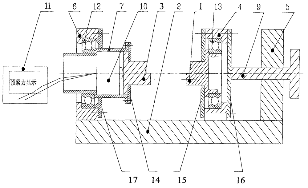
图3为本发明提供的激光焊接装置结构正视示意图;Fig. 3 is the schematic front view of the structure of the laser welding device provided by the present invention;
图4为本发明提供的激光焊接装置结构俯视示意图;Fig. 4 is a schematic top view of the structure of the laser welding device provided by the present invention;
图5为本发明提供的激光焊接装置结构A-A剖视旋转后示意图;Fig. 5 is a schematic diagram of the laser welding device structure A-A provided by the present invention after rotation;
图6为表芯偏心加载侧面示意图。Figure 6 is a schematic side view of the eccentric loading of the watch movement.
图7为表芯偏心加载正面示意图。Fig. 7 is a schematic front view of the watch movement loaded eccentrically.
图中1为推杆,2为支座,3为顶杆,4为中间板,5为右侧板,6为左侧板,7为外罩,8为螺钉,9为螺杆,10为力传感器,11为信号处理电路,12、13为轴承,14为顶杆压盖,15为推杆压盖,16为挡板,17为外罩压盖,18为中间板压板。In the figure, 1 is the push rod, 2 is the support, 3 is the ejector rod, 4 is the middle plate, 5 is the right side plate, 6 is the left side plate, 7 is the outer cover, 8 is the screw, 9 is the screw rod, and 10 is the
具体实施方式 Detailed ways
下面结合附图和实例对本发明进行介绍:The present invention is introduced below in conjunction with accompanying drawing and example:
本发明的目的在于克服现有技术缺陷,提供一种实现整周同轴旋转且预紧力偏心加载的石英挠性加速度计表芯自动焊接装置,如图3、图4和图5所示。The purpose of the present invention is to overcome the defects of the prior art, and provide an automatic welding device for quartz flexible accelerometer cores that realizes full-circle coaxial rotation and eccentric loading of pre-tightening force, as shown in Fig. 3, Fig. 4 and Fig. 5 .
本发明包括支座2、左侧板6、中间板4、右侧板5、顶杆3、推杆1、螺杆9和预紧力测试系统。The present invention comprises a
左侧板6中心为阶梯孔,阶梯孔的大径部分与左侧轴承12的外圈配合,左侧轴承12内圈与外罩7的外圆小径段配合,外罩7通过顶杆压盖14固定于左侧板6,外罩7为阶梯型圆筒结构,其左端由左侧板6的左侧伸出,伸出长度为便于激光焊接机卡盘夹持的尺寸,外罩7通过顶杆压盖14固定于左侧板6,顶杆压盖14为中间带通孔的圆片结构,顶杆压盖14与外罩7连接实现顶杆3的径向定位。The center of the
右侧板5中心为螺纹孔结构,螺杆9的螺纹部分,旋合穿过螺纹通孔,并与固定在中间板4右侧的挡板16接触。The center of the
中间板4中心开有阶梯孔,右侧轴承13外圈与阶梯孔的大径部分配合,右侧轴承13内圈与推杆1阶梯轴的大径端配合,推杆1另一端从推杆压盖15的中心孔伸出,推杆压盖15与中间板4连接,实现推杆1的径向定位,表芯在焊接时左端与顶杆3接触,右端与推杆1接触,中间板4可相对于支座2沿表芯轴向移动,实现表芯的夹紧。There is a stepped hole in the center of the
左侧板2中安装的左侧轴承12和中间板4安装的左侧轴承13成对使用,二者是可承受轴向载荷的轴承,包括角接触球轴承或圆锥滚子轴承。The left side bearing 12 installed in the
顶杆3为阶梯圆柱结构,大径端与外罩7内圆大径配合,小径端穿过顶杆压盖14,小径前端是偏心圆柱结构。The
推杆1大径端与右侧轴承13内圈配合,小径端从推杆压盖15的中心孔伸出,推杆压盖15与中间板4连接,实现推杆1的径向定位,推杆1小径前端是偏心圆柱结构。The large-diameter end of the
推杆1前端的圆柱结构与顶杆3前端的圆柱结构中心线共线,圆柱相对于顶杆3和推杆1中心线的偏移量为表芯偏心加载的偏移量。The cylindrical structure at the front end of the
中间板的支脚19下表面与支座2上表面接触,上表面与中间板压板下表面接触,使中间板4座落于支座2之上The lower surface of the support foot 19 of the middle plate is in contact with the upper surface of the
左侧板6通过螺栓紧固方式与支座2连接,或与支座2做成一体式。The
顶杆3小径前端的偏心圆柱结构与顶杆3连接或成一体式。The eccentric cylindrical structure at the front end of the small diameter of the
推杆1小径前端的偏心圆柱结构可与推杆1连接或成一体式。The eccentric cylinder structure at the front end of the small diameter of the
挡板16可与中间板4连接或成一体式。The
右侧板5与支座2连接或成一体式。The
外罩7内部安装力传感器10,其左端与外罩7内圆阶梯轴轴肩接触,右端与顶杆3接触,力传感器10通过导线与信号处理电路11连接,信号处理电路11用于处理力传感器信号并显示预紧力值。信号处理电路11是带LED显示的信号处理电路。A
轴承12、轴承13、力传感器10、顶杆3、推杆1和螺杆9中心线共线。The center lines of the
本发明工作原理:The working principle of the present invention:
参见图2所示,表芯经V形块定位后,旋转螺杆9推动中间板4沿支座2向表芯方向移动,移动过程中顶杆3前端的小圆柱及推杆1前端的小圆柱中心线共线,且穿过表芯预紧力施力点。继续旋转螺杆9直至推杆1、表芯和顶杆3三者紧密接触,此时精密测力传感器10受力,并在带LED显示的信号处理电路显示力值,当带LED显示的线号处理电路11显示预紧力达到要求后,向上提起本发明装置与V形块脱离,并将本发明装置置于激光焊接机工作台,确保外罩7的中心轴线与激光焊接机卡盘中心共线。用卡盘夹紧外罩7从左侧板6探出的外伸部分,启动激光焊接机,并调用相应焊接程序,从装置顶端对表芯进行焊接。借助于左侧轴承12,激光机卡盘带动外罩7旋转,从而带动推杆1旋转,由于预紧力的存在,表芯和推杆1借助于右侧轴承13实现整周旋转,从而实现表芯整周激光焊接。As shown in Figure 2, after the watch movement is positioned by the V-shaped block, the
本发明未详细说明部分为本领域技术人员公知技术。Parts not described in detail in the present invention are well-known technologies for those skilled in the art.
Claims (2)
Priority Applications (1)
| Application Number | Priority Date | Filing Date | Title |
|---|---|---|---|
| CN201210468293.7A CN102922134B (en) | 2012-11-15 | 2012-11-15 | Device of laser welding meter core |
Applications Claiming Priority (1)
| Application Number | Priority Date | Filing Date | Title |
|---|---|---|---|
| CN201210468293.7A CN102922134B (en) | 2012-11-15 | 2012-11-15 | Device of laser welding meter core |
Publications (2)
| Publication Number | Publication Date |
|---|---|
| CN102922134A true CN102922134A (en) | 2013-02-13 |
| CN102922134B CN102922134B (en) | 2015-04-22 |
Family
ID=47637136
Family Applications (1)
| Application Number | Title | Priority Date | Filing Date |
|---|---|---|---|
| CN201210468293.7A Expired - Fee Related CN102922134B (en) | 2012-11-15 | 2012-11-15 | Device of laser welding meter core |
Country Status (1)
| Country | Link |
|---|---|
| CN (1) | CN102922134B (en) |
Cited By (7)
| Publication number | Priority date | Publication date | Assignee | Title |
|---|---|---|---|---|
| CN104384919A (en) * | 2014-08-21 | 2015-03-04 | 航天科工惯性技术有限公司 | Assembling device for quartz flexible accelerometer movement |
| CN104400236A (en) * | 2014-09-25 | 2015-03-11 | 航天科工惯性技术有限公司 | Welding method and welding structure of accelerometer movement |
| CN107378161A (en) * | 2016-04-29 | 2017-11-24 | 法国大陆汽车公司 | Nickel intensity lug in acceierometer sensor is contacted to the method that boxing connects with bronze connecting pin and brass |
| CN109648169A (en) * | 2018-12-29 | 2019-04-19 | 大连长丰实业总公司 | A kind of aircraft arranges the shell and watch core decomposer of warm table |
| CN112692772A (en) * | 2019-10-23 | 2021-04-23 | 航天科工惯性技术有限公司 | Accelerometer movement disassembling device and method |
| CN114083199A (en) * | 2020-08-24 | 2022-02-25 | 航天科工惯性技术有限公司 | Accelerometer core assembling device and method |
| CN116352434A (en) * | 2023-03-30 | 2023-06-30 | 北京航天控制仪器研究所 | A bow-shaped clip-type quartz flexible accelerometer core clamping device |
Citations (3)
| Publication number | Priority date | Publication date | Assignee | Title |
|---|---|---|---|---|
| US3895789A (en) * | 1972-08-18 | 1975-07-22 | Mero Ag | Rotatable quick-acting axial pressure absorbing chuck for a circular welding machine |
| CN2670045Y (en) * | 2003-11-10 | 2005-01-12 | 中国石油天然气集团公司 | Eccentric self-locking movabme mechanism of all positioning pipe welder |
| CN201300296Y (en) * | 2008-11-28 | 2009-09-02 | 国营三四○五厂 | Positioned welding clamp for torquer unit |
-
2012
- 2012-11-15 CN CN201210468293.7A patent/CN102922134B/en not_active Expired - Fee Related
Patent Citations (3)
| Publication number | Priority date | Publication date | Assignee | Title |
|---|---|---|---|---|
| US3895789A (en) * | 1972-08-18 | 1975-07-22 | Mero Ag | Rotatable quick-acting axial pressure absorbing chuck for a circular welding machine |
| CN2670045Y (en) * | 2003-11-10 | 2005-01-12 | 中国石油天然气集团公司 | Eccentric self-locking movabme mechanism of all positioning pipe welder |
| CN201300296Y (en) * | 2008-11-28 | 2009-09-02 | 国营三四○五厂 | Positioned welding clamp for torquer unit |
Non-Patent Citations (2)
| Title |
|---|
| 王珂: "石英挠性加速度计偏值和标度因数稳定性研究", 《哈尔滨工程大学硕士论文》, 31 December 2011 (2011-12-31), pages 32 - 34 * |
| 赵群: "激光精确焊接工艺在惯性仪表研制中的应用", 《导弹与航天运载技术》, no. 265, 31 December 2003 (2003-12-31) * |
Cited By (12)
| Publication number | Priority date | Publication date | Assignee | Title |
|---|---|---|---|---|
| CN104384919A (en) * | 2014-08-21 | 2015-03-04 | 航天科工惯性技术有限公司 | Assembling device for quartz flexible accelerometer movement |
| CN104384919B (en) * | 2014-08-21 | 2017-02-08 | 航天科工惯性技术有限公司 | Assembling device for quartz flexible accelerometer movement |
| CN104400236A (en) * | 2014-09-25 | 2015-03-11 | 航天科工惯性技术有限公司 | Welding method and welding structure of accelerometer movement |
| CN107378161A (en) * | 2016-04-29 | 2017-11-24 | 法国大陆汽车公司 | Nickel intensity lug in acceierometer sensor is contacted to the method that boxing connects with bronze connecting pin and brass |
| US10744588B2 (en) | 2016-04-29 | 2020-08-18 | Continental Automotive France | Method of welding a nickel strength lug with a bronze connecting pin and a brass contact ring in an accelerometer sensor |
| CN109648169A (en) * | 2018-12-29 | 2019-04-19 | 大连长丰实业总公司 | A kind of aircraft arranges the shell and watch core decomposer of warm table |
| CN109648169B (en) * | 2018-12-29 | 2021-04-23 | 大连长丰实业总公司 | Shell and watch core decomposition device of aircraft exhaust thermometer |
| CN112692772A (en) * | 2019-10-23 | 2021-04-23 | 航天科工惯性技术有限公司 | Accelerometer movement disassembling device and method |
| CN112692772B (en) * | 2019-10-23 | 2022-08-05 | 航天科工惯性技术有限公司 | Accelerometer movement disassembling device and method |
| CN114083199A (en) * | 2020-08-24 | 2022-02-25 | 航天科工惯性技术有限公司 | Accelerometer core assembling device and method |
| CN114083199B (en) * | 2020-08-24 | 2023-10-17 | 航天科工惯性技术有限公司 | Accelerometer core assembly device and method |
| CN116352434A (en) * | 2023-03-30 | 2023-06-30 | 北京航天控制仪器研究所 | A bow-shaped clip-type quartz flexible accelerometer core clamping device |
Also Published As
| Publication number | Publication date |
|---|---|
| CN102922134B (en) | 2015-04-22 |
Similar Documents
| Publication | Publication Date | Title |
|---|---|---|
| CN102922134B (en) | Device of laser welding meter core | |
| CN110230608B (en) | A dynamic balancing mandrel with end teeth and an impeller mounting structure | |
| CN205620127U (en) | Thin wall bearing examines test table static load testing arrangement | |
| CN201913385U (en) | Fixture welding hub by friction stir welding | |
| CN104712626A (en) | Accelerometer pendulum piece set bonding device of expandable mandrel structure | |
| CN104990694B (en) | Motor turning rod assembly and ball stud experimental rig | |
| CN104236772B (en) | A kind of oscillating bearing staring torque measuring device and measuring method | |
| KR101462824B1 (en) | Tire holding member for tire testing machine | |
| CN104713774B (en) | Spring assembly limiting type rock specimen fixing device for direct tensile test | |
| CN105547701A (en) | Dynamic load testing device for thin-wall bearing detecting table | |
| CN106197850A (en) | Automatic clamping device for flexible flywheel dynamic balancing measurement | |
| CN107271307A (en) | A small load impact wear test bench with tangential acceleration | |
| CN206038223U (en) | A automatic clamping device for flexible flywheel dynamic balancing test | |
| KR101067171B1 (en) | Automatic rotating inspection equipment for generator rotor retaining ring | |
| US20150290734A1 (en) | Electric discharge machine with rotary table | |
| CN103439054A (en) | Blind hole impeller dynamic balancing testing device | |
| CN103122981B (en) | A kind of support unit supporting different axle head sized balls leading screw | |
| CN105003554B (en) | Hub bearing outer ring channel level detection apparatus rotating mechanism | |
| CN204868545U (en) | Bitonic whole centre frame of high accuracy | |
| CN201693412U (en) | Shaft external grinding auxiliary device of internal shaft bearing | |
| CN203566158U (en) | Multi-angle rotation control device | |
| CN207488160U (en) | Multilayer material binding strength test device | |
| CN110017984A (en) | A kind of bearing outer ring rotary test tooling | |
| CN103091038A (en) | Dynamic balance detecting clamping device for flywheel | |
| CN204748107U (en) | Excavator hydraulic traveling motor pivot anchor clamps |
Legal Events
| Date | Code | Title | Description |
|---|---|---|---|
| C06 | Publication | ||
| PB01 | Publication | ||
| C10 | Entry into substantive examination | ||
| SE01 | Entry into force of request for substantive examination | ||
| C14 | Grant of patent or utility model | ||
| GR01 | Patent grant | ||
| CF01 | Termination of patent right due to non-payment of annual fee |
Granted publication date: 20150422 |
|
| CF01 | Termination of patent right due to non-payment of annual fee |