CN102916614A - Photovoltaic system and photovoltaic module with voltage balancers - Google Patents
Photovoltaic system and photovoltaic module with voltage balancers Download PDFInfo
- Publication number
- CN102916614A CN102916614A CN2011102214232A CN201110221423A CN102916614A CN 102916614 A CN102916614 A CN 102916614A CN 2011102214232 A CN2011102214232 A CN 2011102214232A CN 201110221423 A CN201110221423 A CN 201110221423A CN 102916614 A CN102916614 A CN 102916614A
- Authority
- CN
- China
- Prior art keywords
- terminal
- module
- electrically connected
- switch
- voltage balancer
- Prior art date
- Legal status (The legal status is an assumption and is not a legal conclusion. Google has not performed a legal analysis and makes no representation as to the accuracy of the status listed.)
- Pending
Links
Images


Classifications
-
- H—ELECTRICITY
- H10—SEMICONDUCTOR DEVICES; ELECTRIC SOLID-STATE DEVICES NOT OTHERWISE PROVIDED FOR
- H10F—INORGANIC SEMICONDUCTOR DEVICES SENSITIVE TO INFRARED RADIATION, LIGHT, ELECTROMAGNETIC RADIATION OF SHORTER WAVELENGTH OR CORPUSCULAR RADIATION
- H10F77/00—Constructional details of devices covered by this subclass
- H10F77/95—Circuit arrangements
- H10F77/953—Circuit arrangements for devices having potential barriers
- H10F77/955—Circuit arrangements for devices having potential barriers for photovoltaic devices
-
- H—ELECTRICITY
- H02—GENERATION; CONVERSION OR DISTRIBUTION OF ELECTRIC POWER
- H02J—CIRCUIT ARRANGEMENTS OR SYSTEMS FOR SUPPLYING OR DISTRIBUTING ELECTRIC POWER; SYSTEMS FOR STORING ELECTRIC ENERGY
- H02J3/00—Circuit arrangements for AC mains or AC distribution networks
- H02J3/38—Arrangements for parallely feeding a single network by two or more generators, converters or transformers
- H02J3/381—Dispersed generators
-
- H—ELECTRICITY
- H02—GENERATION; CONVERSION OR DISTRIBUTION OF ELECTRIC POWER
- H02J—CIRCUIT ARRANGEMENTS OR SYSTEMS FOR SUPPLYING OR DISTRIBUTING ELECTRIC POWER; SYSTEMS FOR STORING ELECTRIC ENERGY
- H02J3/00—Circuit arrangements for AC mains or AC distribution networks
- H02J3/38—Arrangements for parallely feeding a single network by two or more generators, converters or transformers
- H02J3/46—Controlling of the sharing of output between the generators, converters, or transformers
-
- H02J2101/25—
-
- Y—GENERAL TAGGING OF NEW TECHNOLOGICAL DEVELOPMENTS; GENERAL TAGGING OF CROSS-SECTIONAL TECHNOLOGIES SPANNING OVER SEVERAL SECTIONS OF THE IPC; TECHNICAL SUBJECTS COVERED BY FORMER USPC CROSS-REFERENCE ART COLLECTIONS [XRACs] AND DIGESTS
- Y02—TECHNOLOGIES OR APPLICATIONS FOR MITIGATION OR ADAPTATION AGAINST CLIMATE CHANGE
- Y02E—REDUCTION OF GREENHOUSE GAS [GHG] EMISSIONS, RELATED TO ENERGY GENERATION, TRANSMISSION OR DISTRIBUTION
- Y02E10/00—Energy generation through renewable energy sources
- Y02E10/50—Photovoltaic [PV] energy
- Y02E10/56—Power conversion systems, e.g. maximum power point trackers
Landscapes
- Engineering & Computer Science (AREA)
- Power Engineering (AREA)
- Charge And Discharge Circuits For Batteries Or The Like (AREA)
- Dc-Dc Converters (AREA)
- Inverter Devices (AREA)
Abstract
一种光伏模块及系统,该模块包括彼此串联电连接的N个子模块,任意一个子模块(最后一个除外)的负端子均电连接到紧跟其后的子模块的正端子;N-1个电压平衡器,每个平衡器均具有第一、第二和第三端子。任意一个平衡器(最后一个除外)的第二端子均电连接到紧跟其后的平衡器的第三端子,任意一个平衡器(最后一个除外)的第三端子均电连接到紧跟其后的平衡器的第一端子;第一个平衡器的第一端子电连接到第一个子模块的正端子;最后一个平衡器的第二端子电连接到最后一个子模块的负端子。第j个平衡器的第三端子电连接到第j个子模块的负端子和第(j+1)个子模块的正端子,j=1,2,3,......,(N-1)。本发明每个子模块均能接近于最大输出功率而运行。
A photovoltaic module and system, the module includes N sub-modules electrically connected in series, the negative terminal of any sub-module (except the last one) is electrically connected to the positive terminal of the sub-module immediately following it; N-1 Voltage balancers each having first, second and third terminals. The second terminal of any one balancer (except the last one) is electrically connected to the third terminal of the immediately following balancer, and the third terminal of any one balancer (except the last one) is electrically connected to the immediately following The first terminal of the balancer; the first terminal of the first balancer is electrically connected to the positive terminal of the first sub-module; the second terminal of the last balancer is electrically connected to the negative terminal of the last sub-module. The third terminal of the jth balancer is electrically connected to the negative terminal of the jth submodule and the positive terminal of the (j+1)th submodule, j=1, 2, 3,..., (N- 1). Each sub-module of the present invention can operate close to the maximum output power.
Description
技术领域 technical field
本发明涉及一种光伏(photovoltaic)系统,尤其涉及一种采用一个或多个电压平衡器来平衡光伏模块或其子模块的输出电压的光伏系统。The present invention relates to a photovoltaic (photovoltaic) system, in particular to a photovoltaic system using one or more voltage balancers to balance the output voltage of a photovoltaic module or its sub-modules.
背景技术 Background technique
光伏(PV)模块越来越多地用于从入射到太阳能电池上的太阳光能生成电能。典型地,PV模块是用多个串联连接的太阳能电池10形成的,多个太阳能电池10可以分组成多个串联连接的子模块20。例如,如图10所示,有3个串联连接的子模块,在每一个子模块中有18-20个串联连接的太阳能电池。基于PV系统的期望输出电压和功率范围,通过设置多个串联成串的PV模块、且有时通过并行设置多个串联连接的PV模块串而能够形成PV系统。实践中,例如,由于子模块被临时遮挡、一个或多个太阳电池受到污染、或者甚至由于太阳能电池的性能可能随着年深日久而恶化的蔓延,不同的子模块20中的单个太阳能电池10的输出功率之间存在差异。Photovoltaic (PV) modules are increasingly used to generate electrical energy from sunlight incident on solar cells. Typically, a PV module is formed with a plurality of
由于太阳能电池的电流源型(current-source-type)性能,以及由于每个电池的太阳能电流值依赖于入射光量,因此,不是所有的在PV模块内串联连接的电流源都可以具有相同的值。为了防止最弱的电池的电流决定整个PV模块的输出电流,典型地,在PV模块内使用旁路二极管30。如图10所示,每一个旁路二极管30并联连接到各自的子模块20。一旦一个子模块20被部分遮挡,则子模块20中的旁路二极管30将相应地处于导通状态,从而为模块电流Io提供通路。Due to the current-source-type properties of solar cells, and because the value of the solar current per cell depends on the amount of incident light, not all current sources connected in series within a PV module can have the same value . To prevent the current of the weakest cell from dominating the output current of the entire PV module, a
然而,使用旁路二极管的缺点在于PV模块的相关缺省风险(default-risk)和该模块不再是相反极性(reverse-polarity)的事实。二极管会被极性损坏。However, the disadvantage of using bypass diodes is the associated default-risk of the PV module and the fact that the module is no longer reverse-polarity. Diodes can be damaged by polarity.
因此,迄今为止在本领域中存在亟待解决上述不足和缺陷的需求,而该需求尚未解决。Thus, there is heretofore an urgent need in the art to address the above-mentioned deficiencies and deficiencies, which need has not yet been resolved.
发明内容 Contents of the invention
为克服现有技术的缺陷,本发明的一个方面涉及一种光伏(PV)模块。在一个实施例中,该模块包括N个子模块,N为大于1的整数,每一个子模块均具有正端子和负端子,所述N个子模块彼此串联电连接,从而使得除了最后一个子模块之外,任意一个子模块的所述负端子均电连接到紧跟其后的子模块的所述正端子。To overcome the deficiencies of the prior art, one aspect of the present invention relates to a photovoltaic (PV) module. In one embodiment, the module includes N submodules, N is an integer greater than 1, each submodule has a positive terminal and a negative terminal, and the N submodules are electrically connected to each other in series, so that all but the last submodule Furthermore, the negative terminal of any one sub-module is electrically connected to the positive terminal of the immediately following sub-module.
该模块还包括N-1个电压平衡器。每一个电压平衡器均具有第一端子、第二端子和第三端子,除了最后一个电压平衡器之外,任意一个电压平衡器的所述第二端子均电连接到紧跟其后的电压平衡器的所述第三端子;除了最后一个电压平衡器之外,任意一个电压平衡器的所述第三端子均电连接到紧跟其后的电压平衡器的所述第一端子;第一个电压平衡器的所述第一端子电连接到第一个子模块的所述正端子;最后一个电压平衡器的所述第二端子电连接到最后一个子模块的所述负端子;以及第j个电压平衡器的所述第三端子电连接到第j个子模块的所述负端子和第(j+1)个子模块的所述正端子这两者,j=1,2,3,......,(N-1)。The module also includes N-1 voltage balancers. Each voltage balancer has a first terminal, a second terminal and a third terminal, the second terminal of any voltage balancer except the last one being electrically connected to the immediately following voltage balancer said third terminal of any voltage balancer except the last voltage balancer; said third terminal of any one voltage balancer is electrically connected to said first terminal of the immediately following voltage balancer; the first said first terminal of a voltage balancer is electrically connected to said positive terminal of a first submodule; said second terminal of a last voltage balancer is electrically connected to said negative terminal of a last submodule; and The third terminal of the voltage balancer is electrically connected to both the negative terminal of the jth submodule and the positive terminal of the (j+1)th submodule, j=1, 2, 3, .. ...., (N-1).
在一个实施例中,每一个电压平衡器均包括:第一开关S1和第二开关S2,电耦接在所述第一端子与第二端子之间;第一二极管D1和第二二极管D2,每一个二极管均并联电耦接到各自的开关;电感器L,电耦接在所述第一开关和第二开关的结合处与所述第三端子之间;以及电耦接在所述第一端子与第三端子之间的第一电容器C1和电耦接在所述第二端子与第三端子之间的第二电容器C2。In one embodiment, each voltage balancer includes: a first switch S1 and a second switch S2 electrically coupled between the first terminal and the second terminal; a first diode D1 and a second two Diode D2, each diode is electrically coupled to a respective switch in parallel; an inductor L is electrically coupled between the junction of the first switch and the second switch and the third terminal; and electrically coupled A first capacitor C1 between the first terminal and the third terminal and a second capacitor C2 electrically coupled between the second terminal and the third terminal.
此外,每一个电压平衡器还包括脉冲发生器,电耦接到所述第一开关S1和第二开关S2,用于提供驱动所述第一开关S1和第二开关S2的一个或多个驱动信号,其中所述一个或多个驱动信号具有补偿的50%占空比。In addition, each voltage balancer further includes a pulse generator, electrically coupled to the first switch S1 and the second switch S2, for providing one or more drives for driving the first switch S1 and the second switch S2 signals, wherein the one or more drive signals have a compensated 50% duty cycle.
在一个实施例中,每一个电压平衡器还包括使能逻辑电路,电耦接在所述脉冲发生器与所述第一端子和第三端子之间,其中所述使能逻辑电路用于感测输入电压V1和V2,从而使得当所述输入电压V1和V2的差值低于预定阈值时,所述使能逻辑电路禁用所述脉冲发生器并关闭所述电压平衡器,其中所述输入电压V1和V2分别是所述第一端子和第三端子处的电压。In one embodiment, each voltage balancer further includes an enable logic circuit electrically coupled between the pulse generator and the first terminal and the third terminal, wherein the enable logic circuit is used for sensing The input voltages V1 and V2 are measured, so that when the difference between the input voltages V1 and V2 is lower than a predetermined threshold, the enable logic circuit disables the pulse generator and turns off the voltage balancer, wherein the input Voltages V1 and V2 are the voltages at said first and third terminals, respectively.
PV模块还包括DC/DC转换器,具有正输入端、负输入端、正输出端和负输出端,其中所述正输入端和负输入端分别电耦接到第一个子模块的所述正端子和最后一个子模块的所述负端子。在一个实施例中,该DC/DC转换器包括:一对开关,电连接在所述正端子与负端子之间;电感器,电耦接在所述正输出端与所述一对开关的结合处之间;以及一对电容器,一个电容器电耦接在所述正输入端与所述负输入端之间,另一个电容器电耦接在所述正输出端与所述负输出端之间;其中,所述负输出端电连接到所述负输入端。The PV module also includes a DC/DC converter having a positive input terminal, a negative input terminal, a positive output terminal and a negative output terminal, wherein the positive input terminal and the negative input terminal are electrically coupled to the first sub-module respectively. positive terminal and the negative terminal of the last submodule. In one embodiment, the DC/DC converter includes: a pair of switches electrically connected between the positive terminal and the negative terminal; an inductor electrically coupled between the positive output terminal and the pair of switches Between junctions; and a pair of capacitors, one capacitor is electrically coupled between the positive input terminal and the negative input terminal, and the other capacitor is electrically coupled between the positive output terminal and the negative output terminal ; Wherein, the negative output terminal is electrically connected to the negative input terminal.
在一个实施例中,每一个子模块均包括彼此串联电连接的多个PV电池。In one embodiment, each submodule includes a plurality of PV cells electrically connected in series with each other.
本发明的另一方面涉及一种PV系统。一个实施例的PV系统包括多个PV模块,每一个所述PV模块如上所述,所述多个PV模块彼此串联电连接,从而使得除了最后一个PV模块之外,任意一个PV模块的所述负端子均电连接到紧跟其后的PV模块的所述正端子。Another aspect of the invention relates to a PV system. The PV system of one embodiment includes a plurality of PV modules, each of which is as described above, and the plurality of PV modules are electrically connected to each other in series such that, except for the last PV module, the The negative terminals are each electrically connected to said positive terminal of the immediately following PV module.
该PV系统还包括逆变器,具有电连接到第一个PV模块的所述正端子的第一输入端、电连接到最后一个PV模块的所述负端子的第二输入端、以及电连接到电网或负载的第一输出端和第二输出端,其中,所述逆变器具有最大功率点追踪(MPPT)功能。The PV system also includes an inverter having a first input electrically connected to said positive terminal of the first PV module, a second input electrically connected to said negative terminal of the last PV module, and electrically connected to the first output terminal and the second output terminal of the grid or load, wherein the inverter has a maximum power point tracking (MPPT) function.
本发明的又一方面涉及一种PV模块。在一个实施例中,该PV模块包括:N个子模块,N为大于2的整数,每一个子模块均具有正端子和负端子,所述N个子模块彼此串联电连接,从而使得除了最后一个子模块之外,任意一个子模块的所述负端子均电连接到紧跟其后的子模块的所述正端子;以及N个电压平衡器,每一个电压平衡器均具有第一端子、第二端子和第三端子,其中,除了最后一个电压平衡器之外,任意一个电压平衡器的所述第二端子均电连接到紧跟其后的电压平衡器的所述第三端子;除了最后一个电压平衡器之外,任意一个电压平衡器的所述第三端子均电连接到紧跟其后的电压平衡器的所述第一端子;第一个电压平衡器的所述第一端子电连接到第一个子模块的所述正端子;最后一个电压平衡器的所述第二端子和第三端子分别电连接到最后一个子模块的B-out端子和所述负端子;以及第j个电压平衡器的所述第三端子电连接到第j个子模块的所述负端子和第(j+1)个子模块的所述正端子这两者,j=1,2,3,......,(N-1);以及第一个电压平衡器的所述第三端子电连接到B-in端子。Yet another aspect of the invention relates to a PV module. In one embodiment, the PV module includes: N sub-modules, N is an integer greater than 2, each sub-module has a positive terminal and a negative terminal, the N sub-modules are electrically connected to each other in series, so that all but the last sub-module Outside the module, the negative terminal of any one sub-module is electrically connected to the positive terminal of the sub-module immediately following it; and N voltage balancers, each voltage balancer has a first terminal, a second terminal and a third terminal, wherein, except for the last voltage balancer, said second terminal of any voltage balancer is electrically connected to said third terminal of the immediately following voltage balancer; except for the last In addition to the voltage balancer, the third terminal of any one voltage balancer is electrically connected to the first terminal of the following voltage balancer; the first terminal of the first voltage balancer is electrically connected to to the positive terminal of the first submodule; the second terminal and the third terminal of the last voltage balancer are electrically connected to the B-out terminal and the negative terminal of the last submodule, respectively; and the jth The third terminal of the voltage balancer is electrically connected to both the negative terminal of the jth submodule and the positive terminal of the (j+1)th submodule, j=1, 2, 3, … ..., (N-1); and said third terminal of the first voltage balancer is electrically connected to the B-in terminal.
在一个实施例中,每一个电压平衡器均具有:第一开关S1和第二开关S2,电耦接在所述第一端子与第二端子之间;第一二极管D1和第二二极管D2,每一个二极管均并联电耦接到各自的开关;电感器L,电耦接在所述第一开关和第二开关的结合处与所述第三端子之间;以及电耦接在所述第一端子与第三端子之间的第一电容器C1和电耦接在所述第二端子与第三端子之间的第二电容器C2。In one embodiment, each voltage balancer has: a first switch S1 and a second switch S2 electrically coupled between the first terminal and the second terminal; a first diode D1 and a second two Diode D2, each diode is electrically coupled to a respective switch in parallel; an inductor L is electrically coupled between the junction of the first switch and the second switch and the third terminal; and electrically coupled A first capacitor C1 between the first terminal and the third terminal and a second capacitor C2 electrically coupled between the second terminal and the third terminal.
此外,每一个电压平衡器还包括脉冲发生器,电耦接到所述第一开关S1和第二开关S2,用于提供驱动所述第一开关S1和第二开关S2的一个或多个驱动信号,其中所述一个或多个驱动信号具有补偿的50%占空比。In addition, each voltage balancer further includes a pulse generator, electrically coupled to the first switch S1 and the second switch S2, for providing one or more drives for driving the first switch S1 and the second switch S2 signals, wherein the one or more drive signals have a compensated 50% duty cycle.
在一个实施例中,每一个电压平衡器还包括使能逻辑电路,电耦接在所述脉冲发生器与所述第一端子和第三端子之间,其中所述使能逻辑电路被配置为感测输入电压V1和V2,从而使得当所述输入电压V1和V2的差值低于预定阈值时,所述使能逻辑电路禁用所述脉冲发生器并关闭所述电压平衡器,其中所述输入电压V1和V2分别是所述第一端子和第三端子处的电压。In one embodiment, each voltage balancer further includes an enable logic circuit electrically coupled between the pulse generator and the first terminal and the third terminal, wherein the enable logic circuit is configured to sensing input voltages V1 and V2 such that the enable logic disables the pulse generator and turns off the voltage balancer when the difference between the input voltages V1 and V2 is below a predetermined threshold, wherein the The input voltages V1 and V2 are the voltages at said first and third terminals, respectively.
在一个实施例中,每一个子模块均包括彼此串联电连接的多个PV电池。In one embodiment, each submodule includes a plurality of PV cells electrically connected in series with each other.
本发明的再一方面涉及一种PV系统。在一个实施例中,该PV系统包括:多个PV模块,每一个PV模块如上所述,所述多个PV模块彼此电连接,从而使得除了最后一个PV模块之外,任意一个PV模块的所述负端子和B-out端子均分别电连接到紧跟其后的PV模块的所述正端子和B-in端子;以及逆变器,具有电连接到第一个PV模块的所述正端子的第一输入端、电连接到最后一个PV模块的所述负端子的第二输入端、电连接到电网或负载的第一输出端和第二输出端,其中,所述逆变器具有MPPT功能。Yet another aspect of the invention relates to a PV system. In one embodiment, the PV system includes: a plurality of PV modules, each PV module as described above, the plurality of PV modules are electrically connected to each other, so that all but the last PV module, all said negative terminal and B-out terminal are both electrically connected respectively to said positive terminal and B-in terminal of the immediately following PV module; and an inverter having said positive terminal electrically connected to a first PV module A first input terminal electrically connected to the negative terminal of the last PV module, a first output terminal electrically connected to the grid or a load, and a second output terminal electrically connected to the grid or load, wherein the inverter has an MPPT Function.
本发明的又一方面涉及一种PV系统。在一个实施例中,该PV系统包括:多个PV模块,每一个PV模块均包括正端子和负端子,所述多个PV模块彼此串联电连接,从而使得除了最后一个PV模块之外,任意一个PV模块的所述负端子均电连接到紧跟其后的PV模块的所述正端子;以及一个或多个电压平衡器,每一个电压平衡器均具有第一端子、第二端子和第三端子;以及逆变器,具有电连接到第一个PV模块的所述正端子的第一输入端、电连接到最后一个PV模块的所述负端子的第二输入端、以及电连接到电网或负载的第一输出端和第二输出端,其中,所述逆变器具有MPPT功能。Yet another aspect of the invention relates to a PV system. In one embodiment, the PV system includes a plurality of PV modules each including a positive terminal and a negative terminal, the plurality of PV modules being electrically connected in series with each other such that all but the last PV module said negative terminal of one PV module is each electrically connected to said positive terminal of an immediately following PV module; and one or more voltage balancers each having a first terminal, a second terminal and a second terminal. three terminals; and an inverter having a first input electrically connected to the positive terminal of the first PV module, a second input electrically connected to the negative terminal of the last PV module, and a second input electrically connected to the negative terminal of the last PV module. The first output terminal and the second output terminal of the grid or load, wherein the inverter has an MPPT function.
在一个实施例中,每一个电压平衡器均具有:第一开关S1和第二开关S2,电耦接在所述第一端子与第二端子之间;第一二极管D1和第二二极管D2,每一个二极管均并联电耦接到各自的开关;电感器L,电耦接在所述第一开关和第二开关的结合处与所述第三端子之间;以及电耦接在所述第一端子与第三端子之间的第一电容器C1和电耦接在所述第二端子与第三端子之间的第二电容器C2。In one embodiment, each voltage balancer has: a first switch S1 and a second switch S2 electrically coupled between the first terminal and the second terminal; a first diode D1 and a second two Diode D2, each diode is electrically coupled to a respective switch in parallel; an inductor L is electrically coupled between the junction of the first switch and the second switch and the third terminal; and electrically coupled A first capacitor C1 between the first terminal and the third terminal and a second capacitor C2 electrically coupled between the second terminal and the third terminal.
此外,每一个电压平衡器还包括:脉冲发生器,电耦接到所述第一开关S1和第二开关S2,用于提供驱动所述第一开关S1和第二开关S2的一个或多个驱动信号,其中所述一个或多个驱动信号具有补偿的50%占空比。In addition, each voltage balancer also includes: a pulse generator, electrically coupled to the first switch S1 and the second switch S2, for providing one or more pulse generators for driving the first switch S1 and the second switch S2 drive signals, wherein the one or more drive signals have a compensated 50% duty cycle.
在一个实施例中,每一个电压平衡器还包括使能逻辑电路,电耦接在所述脉冲发生器与所述第一端子和第三端子之间,其中所述使能逻辑电路用于感测输入电压V1和V2,从而使得当所述输入电压V1和V2的差值低于预定阈值时,所述使能逻辑电路禁用所述脉冲发生器并关闭所述电压平衡器,其中所述输入电压V1和V2分别是所述第一端子和第三端子处的电压。在一个实施例中,每个子模块均包括彼此串联电连接的多个PV电池。In one embodiment, each voltage balancer further includes an enable logic circuit electrically coupled between the pulse generator and the first terminal and the third terminal, wherein the enable logic circuit is used for sensing The input voltages V1 and V2 are measured, so that when the difference between the input voltages V1 and V2 is lower than a predetermined threshold, the enable logic circuit disables the pulse generator and turns off the voltage balancer, wherein the input Voltages V1 and V2 are the voltages at said first and third terminals, respectively. In one embodiment, each submodule includes a plurality of PV cells electrically connected in series with each other.
在一个实施例中,每一个PV模块均包括彼此串联电连接的多个子模块,每一个子模块均包括彼此串联电连接的多个PV电池。In one embodiment, each PV module includes a plurality of sub-modules electrically connected in series with each other, each sub-module includes a plurality of PV cells electrically connected in series with each other.
对于本发明的这种结构,如果一个PV子模块被部分遮挡,则从该子模块输出的电流可能下降,然而电压V1和V2由于电压平衡器VBk而保持相同。即使在部分遮挡情况下,PV模块100仍然使得每一个子模块能接近于最大输出功率而运行。With this configuration of the invention, if a PV sub-module is partially shaded, the current output from that sub-module may drop, however the voltages V1 and V2 remain the same due to the voltage balancer VBk. Even under partial shading, the
下面将结合附图对优选实施例进行描述,本发明的这些和其他方面将因所述描述而变得清楚,尽管在不脱离本文公开的新颖概念的精神和范围的情况下可以对其进行各种变型和修改。These and other aspects of the invention will become apparent from the following description of preferred embodiments, taken in conjunction with the accompanying drawings, although modifications may be made thereto without departing from the spirit and scope of the novel concepts disclosed herein. variations and modifications.
附图说明 Description of drawings
附图用来示出本发明的一个或多个实施例,且书面说明书用于解释本发明的原理。只要可能,所有附图中用相同的附图标记指代实施例中相同或相似的元件,其中:The drawings illustrate one or more embodiments of the invention, and the written description serves to explain principles of the invention. Wherever possible, the same reference numbers will be used throughout the drawings to refer to the same or like elements of the embodiments, wherein:
图1示意性地示出根据本发明一个实施例的光伏(PV)模块;Figure 1 schematically illustrates a photovoltaic (PV) module according to one embodiment of the present invention;
图2示意性地示出根据本发明一个实施例的PV模块中用到的电压平衡器;Figure 2 schematically shows a voltage balancer used in a PV module according to one embodiment of the present invention;
图3示意性地示出根据本发明另一个实施例的PV模块中用到的电压平衡器;Fig. 3 schematically shows a voltage balancer used in a PV module according to another embodiment of the present invention;
图4示意性地示出根据本发明一个实施例的PV模块;Figure 4 schematically illustrates a PV module according to one embodiment of the present invention;
图5示意性地示出根据本发明一个实施例的PV模块中用到的DC/DC转换器;Figure 5 schematically shows a DC/DC converter used in a PV module according to one embodiment of the present invention;
图6示意性地示出根据本发明一个实施例的包括多个PV模块的PV系统;Figure 6 schematically illustrates a PV system comprising a plurality of PV modules according to one embodiment of the present invention;
图7示意性地示出根据本发明一个实施例的PV模块;Figure 7 schematically illustrates a PV module according to one embodiment of the present invention;
图8示意性地示出根据本发明一个实施例的包括多个PV模块的PV系统;Figure 8 schematically illustrates a PV system comprising a plurality of PV modules according to one embodiment of the present invention;
图9示意性地示出根据本发明另一个实施例的包括多个PV模块的PV系统;以及Figure 9 schematically illustrates a PV system comprising a plurality of PV modules according to another embodiment of the present invention; and
图10示意性地示出现有的PV模块。Fig. 10 schematically shows an existing PV module.
具体实施方式 Detailed ways
下文将参照附图更为充分地描述本发明,附图中示出了本发明的示例性实施例。然而,本发明可以以多种不同形式实现,并且不应当理解为局限于本文列出的实施例。更确切地说,这些实施例的提供使得公开内容将会详尽而完整,并且将向本领域技术人员充分表明本发明的范围。全文中相似的附图标记指代相似的元件。The present invention will be described more fully hereinafter with reference to the accompanying drawings, in which exemplary embodiments of the invention are shown. However, this invention may be embodied in many different forms and should not be construed as limited to the embodiments set forth herein. Rather, these embodiments are provided so that this disclosure will be thorough and complete, and will fully convey the scope of the invention to those skilled in the art. Like reference numerals refer to like elements throughout.
本文使用的术语只是为了描述特定实施例的目的,并不是为了限制本发明。除非上下文中清楚地指出,否则本文用到的单数形式的“一”、“一个”和“该”也旨在包括复数形式。还应当理解,当本文使用词语“包含(comprise)”和/或“包含(comprising)”,或者“包括(includes)”和/或“包括(including)”,或者“有(has)”和/或“具有(having)”时,其明确所陈述的特征、区域、整体、步骤、操作、元件和/或组件的存在,但并不排除一个或多个其他特征、区域、整体、步骤、操作、元件、组件和/或其组合的存在或追加。The terminology used herein is for the purpose of describing particular embodiments only and is not intended to be limiting of the invention. As used herein, the singular forms "a", "an" and "the" are intended to include the plural forms as well, unless the context clearly dictates otherwise. It should also be understood that when the words "comprise" and/or "comprising", or "includes" and/or "including", or "has" and/or or "having (having)", it explicitly states the existence of the stated features, regions, integers, steps, operations, elements and/or assemblies, but does not exclude the existence of one or more other features, regions, integers, steps, operations , the presence or addition of elements, components and/or combinations thereof.
除非另有定义,否则本文用到的所有词语(包括技术和科学用语)都与本发明所属技术领域中一个普通技术人员通常理解的含义相同。还应当理解,例如在常用词典中定义的词语应当被理解为具有与它们在相关技术领域和本文的上下文中一致的含义,并且除非本文明确定义,否则不应当被理想化或过于形式化地理解。Unless otherwise defined, all words (including technical and scientific terms) used herein have the same meaning as commonly understood by one of ordinary skill in the art to which this invention belongs. It should also be understood that words defined, for example, in commonly used dictionaries should be understood to have meanings consistent with their context in the relevant technical field and this text, and should not be interpreted ideally or overly formally unless they are clearly defined herein .
本文用到的“左右”、“大约”或者“近似”应当通常是指落在给定数值或范围的百分之二十以内,优选为百分之十以内,更优选为百分之五以内。本文给出的数量是近似值,意味着如果没有明确说明,则词语“左右”、“大约”或“约”是能够被推及的。"Around", "approximately" or "approximately" as used herein shall generally mean within 20 percent, preferably within 10 percent, and more preferably within 5 percent of a given value or range . Quantities given herein are approximate, meaning that the words "around", "approximately" or "approximately" can be inferred if not expressly stated.
将结合附图1-9来描述本发明的实施例。根据本发明的目的,如同本文所具体表达和广泛描述的那样,本发明的一个方面涉及一种PV模块及其应用,其使用一个或多个电压平衡器来平衡PV模块的PV子模块的输出电压。Embodiments of the present invention will be described with reference to the accompanying drawings 1-9. In accordance with the purposes of the present invention, as embodied and broadly described herein, one aspect of the present invention relates to a PV module and use thereof, which uses one or more voltage balancers to balance the outputs of the PV sub-modules of the PV module Voltage.
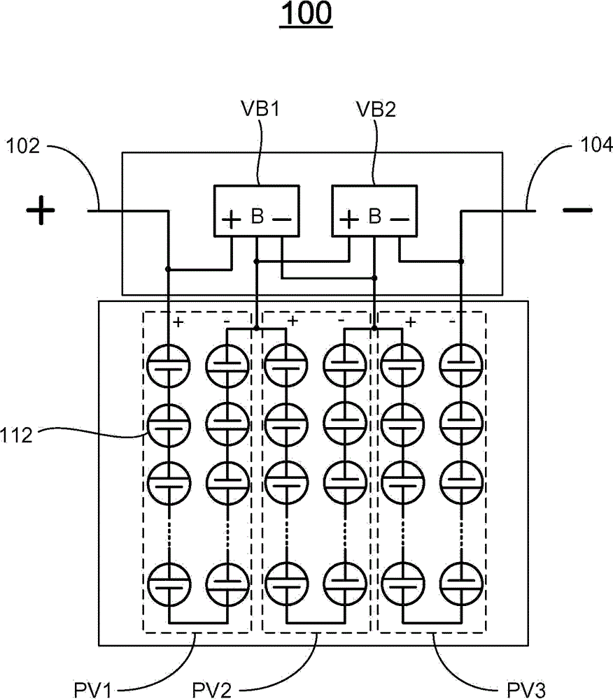
参照图1,示出了根据本发明一个实施例的PV模块100。PV模块100具有正极性(+)的第一输出端口102和负极性(-)的第二输出端口104。PV模块100包括N个子模块,{PVj},j=2,3,4,......,N,N为大于1的整数。每一个子模块PVj均包括多个彼此串联电连接的PV电池,从而一端具有正端子(+)而另一端具有负端子(-)。N个子模块{PVj}彼此串联电连接,从而使得除了最后一个子模块之外,任意一个子模块的负端子(-)均电连接到紧跟其后的子模块的正端子(+)。在图1示出的示例性实施例中,N=3。第一个子模块PV(1)的负端子(-)电连接到第二个子模块PV(2)的正端子(+);第二个子模块PV2的负端子(-)电连接到第三个子模块PV3的正端子(+)。第一个子模块PV1的正端子(+)电连接到PV模块100的第一输出端口102,而第三个子模块PV3的负端子(-)电连接到PV模块100的第二输出端口104。Referring to FIG. 1 , a
PV模块100还包括(N-1)个电压平衡器,{VBk},k=1,2,3,......,(N-1)。每一个电压平衡器VBk均具有第一端子(+)、第二端子(-)和第三端子(B)。除了最后一个电压平衡器之外,任意一个电压平衡器的第二端子(-)均电连接到紧跟其后的电压平衡器的第三端子(B)。除了最后一个电压平衡器之外,任意一个电压平衡器的第三端子(B)均电连接到紧跟其后的电压平衡器的第一端子(+)。此外,第一个电压平衡器VB1的第一端子(+)电连接到第一个子模块PV1的正端子(+)。最后一个电压平衡器VB(N-1)的第二端子(-)电连接到最后一个子模块PVN的负端子(-)。第k个电压平衡器VBk的第三端子(B)电连接到第k个子模块PVk的负端子(-)和第(k+1)个子模块PV(k+1)的正端子(+)这两者。The
例如,如图1所示,第一个电压平衡器VB1的第二端子(-)电连接到第二个电压平衡器VB2的第三端子(B);第一个电压平衡器VB1的第三端子(B)电连接到第二个电压平衡器VB2的第一端子(+)。此外,第一个电压平衡器VB1的第一端子(+)电连接到第一个子模块PV1的正端子(+)。第二个电压平衡器VB2的第二端子(-)电连接到第三个子模块PV3的负端子(-)。第一个电压平衡器VB1的第三端子(B)电连接到第一个子模块PV1的负端子(-)和第二个子模块PV2的正端子(+)这两者。第二个电压平衡器VB2的第三端子(B)电连接到第二个子模块PV2的负端子(-)和第三个子模块PV3的正端子(+)这两者。VB1为PV1和PV2提供平衡功能,VB2为PV2和PV3提供平衡功能。For example, as shown in Figure 1, the second terminal (-) of the first voltage balancer VB1 is electrically connected to the third terminal (B) of the second voltage balancer VB2; the third terminal (-) of the first voltage balancer VB1 Terminal (B) is electrically connected to the first terminal (+) of the second voltage balancer VB2. Furthermore, the first terminal (+) of the first voltage balancer VB1 is electrically connected to the positive terminal (+) of the first sub-module PV1. The second terminal (-) of the second voltage balancer VB2 is electrically connected to the negative terminal (-) of the third sub-module PV3. The third terminal (B) of the first voltage balancer VB1 is electrically connected to both the negative terminal (-) of the first submodule PV1 and the positive terminal (+) of the second submodule PV2. The third terminal (B) of the second voltage balancer VB2 is electrically connected to both the negative terminal (−) of the second submodule PV2 and the positive terminal (+) of the third submodule PV3. VB1 provides balancing functions for PV1 and PV2, and VB2 provides balancing functions for PV2 and PV3.
参照图2,在一个实施例中,每一个电压平衡器VBk均具有第一开关S1、第二开关S2、第一二极管D1、第二二极管D2、电感器L、第一电容器C1和第二电容器C2。第一开关S1和第二开关S2被电耦接在第一端子(+)与第二端子(-)之间。第一和第二开关S1和S2可以是任意类型的开关,例如,可以是薄膜晶体管(TFT)。第一二极管D1和第二二极管D1的每一个均被并联电耦接到各自的开关。电感器L电耦接在第一和第二开关S1和S2的结合处与第三端子(B)之间。第一电容器C1电耦接在第一端子(+)和第三端子(B)之间。第二电容器C2电耦接在第二端子(-)和第三端子(B)之间。第一和第二电容器C1和C2提供过滤功能,以防止开关频率波动电流穿过子模块{PVk}。2, in one embodiment, each voltage balancer VBk has a first switch S1, a second switch S2, a first diode D1, a second diode D2, an inductor L, a first capacitor C1 and the second capacitor C2. The first switch S1 and the second switch S2 are electrically coupled between the first terminal (+) and the second terminal (-). The first and second switches S1 and S2 may be any type of switches, for example, thin film transistors (TFTs). Each of the first diode D1 and the second diode D1 is electrically coupled in parallel to a respective switch. The inductor L is electrically coupled between the junction of the first and second switches S1 and S2 and the third terminal (B). The first capacitor C1 is electrically coupled between the first terminal (+) and the third terminal (B). The second capacitor C2 is electrically coupled between the second terminal (−) and the third terminal (B). The first and second capacitors C1 and C2 provide a filtering function to prevent the switching frequency fluctuation current from passing through the sub-module {PVk}.
此外,每一个电压平衡器VBk还具有脉冲发生器,该脉冲发生器电耦接到第一和第二开关S1和S2,用于提供具有补偿的50%占空比且用于驱动第一和第二开关S1和S2的一个或多个驱动信号。电压平衡器VBk给与其连接到的子模块{PVk}提供平衡器功能。In addition, each voltage balancer VBk also has a pulse generator electrically coupled to the first and second switches S1 and S2 for providing a 50% duty cycle with compensation and for driving the first and second switches S1 and S2. One or more drive signals for the second switches S1 and S2. The voltage balancer VBk provides a balancer function to the submodule {PVk} to which it is connected.
在图3所示的一个实施例中,每一个电压平衡器VBk还包括使能逻辑电路,该使能逻辑电路电耦接在脉冲发生器与第一端子(+)和第三端子(B)之间。使能逻辑电路决定电压平衡器VBk的打开或关闭。使能逻辑电路被配置为感测输入电压V1和V2,从而使得当输入电压V1和V2之间的差值低于预定阈值时,使能逻辑电路禁用(disable)所述脉冲发生器并关闭电压平衡器VBk。输入电压V1和V2分别是第一端子(+)和第三端子(B)处的电压,分别自耦接到电压平衡器VBk的相应子模块PVk和PV(k+1)输出。In an embodiment shown in FIG. 3, each voltage balancer VBk further includes an enabling logic circuit electrically coupled between the pulse generator and the first terminal (+) and the third terminal (B) between. The enabling logic circuit determines whether the voltage balancer VBk is turned on or off. The enabling logic circuit is configured to sense the input voltages V1 and V2 such that when the difference between the input voltages V1 and V2 is below a predetermined threshold, the enabling logic circuit disables the pulse generator and turns off the voltage Balancer VBk. The input voltages V1 and V2 are the voltages at the first terminal (+) and the third terminal (B), respectively, output from corresponding sub-modules PVk and PV(k+1) coupled to the voltage balancer VBk, respectively.
对于这种结构,如果一个子模块被部分遮挡,则从该子模块输出的电流可能下降,然而电压V1和V2由于电压平衡器VBk而保持相同。即使在被部分遮挡情况下,PV模块100仍然使得每一个子模块能接近于最大输出功率而运行。参照图4和图5,在一个实施例中,PV模块100还包括DC/DC转换器。电压平衡器{VBk}用于保持所有子模块{PVj}的电压平衡,而DC/DC转换器适用于追踪PV模块100的最大输出功率。如图5所示,DC/DC转换器具有正输入端口102、负输入端口104、正输出端口102’以及负输出端口104’。正和负输入端口102和104分别电耦接到第一个子模块PV1的正端子(+)和第四个(最后一个)子模块PV4的负端子(-)。DC/DC转换器包括:电连接在正和负输入端口102和104之间的一对开关S1和S2;电耦接在正输出端口102’与一对开关S1和S2的结合处之间的电感器L;以及一对电容器C1和C2。一个电容器C1电耦接在正和负输入端口102和104之间,另一个电容器C2电耦接在正和负输出端口102’和104’之间。负输出端口104’电连接到负输入端口104。With this configuration, if a sub-module is partially shaded, the current output from that sub-module may drop, however the voltages V1 and V2 remain the same due to the voltage balancer VBk. Even when partially shaded, the
图6示意性地示出了包括如上定义的多个PV模块100的PV系统600。多个PV模块100彼此串联电连接,从而使得除了最后一个PV模块100之外,任意一个PV模块100的负端子(-)均电连接到紧跟其后的PV模块100的正端子(+)。Fig. 6 schematically shows a
PV系统600还包括逆变器610,该逆变器610具有电连接到第一个PV模块100的正端子(+)的第一输入端口612、电连接到最后一个PV模块100的负端子(-)的第二输入端口614。逆变器610具有用于输出功率到电网(grid)/负载的输出端口615。逆变器610具有用于优化PV系统600的功率输出的最大功率点追踪(MPPT)功能。The
参照图7,示意性地示出了根据本发明一个实施例的PV模块700。PV模块700基本上类似于图1-5中所示的PV模块100,只是PV模块700具有B-in端子和B-out端子,并且包括N个电压平衡器{VBk},k=1,2,3,......,N。除了最后一个电压平衡器之外,任意一个电压平衡器的第二端子(-)均电连接到紧跟其后的电压平衡器的第三端子(B)。除了最后一个电压平衡器之外,任意一个电压平衡器的第三端子(B)均电连接到紧跟其后的电压平衡器的第一端子(+)。第一个电压平衡器的第一端子(+)电连接到第一个子模块PV1的正端子(+)。最后一个电压平衡器的第二端子(-)和第三端子(B)分别电连接到最后一个子模块PVN的B-out端子和负端子(-)。第j个电压平衡器的第三端子(B)电连接到第j个子模块的负端子(-)和第(j+1)个子模块的正端子这两者,j=1,2,3,......,(N-1)。第一个电压平衡器PV1的第三端子(B)电连接到B-in端子。Referring to Fig. 7, a
对于PV模块700,第一个、第二个和第三个电压平衡器VB1、VB2和VB3用于平衡三个子模块PV1、PV2和PV3的电压,同时第三个电压平衡器VB3适用于保持PV系统中PV模块700的第二个子模块PV2和紧跟其后的PV模块的第一个子模块PV1之间的电压平衡。For the
图8示意性地示出了具有上面列出的多个PV模块700的PV系统800的一个实施例。多个PV模块700彼此电连接,从而使得除了最后一个PV模块之外,任意一个PV模块的负端子(-)和B-out端子均分别电连接到紧跟其后的PV模块的正端子(+)和B-in端子。Figure 8 schematically illustrates one embodiment of a
PV系统800还包括逆变器810,该逆变器810具有电连接到第一个PV模块100的正端子(+)的第一输入端口812、电连接到最后一个PV模块100的负端子(-)的第二输入端口814。该逆变器810具有用于输出功率到电网或负载的输出端口815。逆变器810具有用于优化PV系统800的功率输出的MPPT功能。The
参照图9,示意性地示出了根据本发明一个实施例的PV系统900。该PV系统包括多个PV模块{PVj},j=1,2,3,......,N。每一个PV模块PVj均具有正端子(+)和负端子(-)。多个PV模块{PVj}彼此串联电连接,从而使得除了最后一个PV模块之外,任意一个PV模块的负端子(-)均电连接到紧跟其后的PV模块的正端子(+)。Referring to Fig. 9, a PV system 900 according to one embodiment of the present invention is schematically shown. The PV system includes a plurality of PV modules {PVj}, j=1, 2, 3, . . . , N. Each PV module PVj has a positive terminal (+) and a negative terminal (-). The plurality of PV modules {PVj} are electrically connected to each other in series such that the negative terminal (-) of any one PV module except the last one is electrically connected to the positive terminal (+) of the immediately following PV module.
在图9所示的示例性实施例中,PV系统900还具有两个电压平衡器VB1和VB2。每一个电压平衡器均具有第一端子(+)、第二端子(-)和第三端子(B)。第一个电压平衡器VB1的第一端子(+)电连接到第一个PV模块PV1和第二个PV模块PV2的结合点;第一个电压平衡器VB1的第三端子(B)电连接到第二个PV模块PV2和第三个PV模块PV3的结合点;并且第一个电压平衡器VB1的第二端子(-)电连接到第三个PV模块PV3和第四个PV模块PV4的结合点。相应地,第一个电压平衡器VB1用于平衡PV模块PV2和PV3的电压。类似地,第二个电压平衡器VB2用于平衡PV模块PV4和PV5的电压。此实施例中,第二个PV模块PV2被遮挡。In the exemplary embodiment shown in FIG. 9, the PV system 900 also has two voltage balancers VB1 and VB2. Each voltage balancer has a first terminal (+), a second terminal (-) and a third terminal (B). The first terminal (+) of the first voltage balancer VB1 is electrically connected to the junction point of the first PV module PV1 and the second PV module PV2; the third terminal (B) of the first voltage balancer VB1 is electrically connected to to the junction of the second PV module PV2 and the third PV module PV3; and the second terminal (-) of the first voltage balancer VB1 is electrically connected to the third PV module PV3 and the fourth PV module PV4 joint point. Correspondingly, the first voltage balancer VB1 is used to balance the voltage of the PV modules PV2 and PV3. Similarly, the second voltage balancer VB2 is used to balance the voltage of PV modules PV4 and PV5. In this embodiment, the second PV module PV2 is shaded.
此外,PV系统900包括逆变器910,该逆变器910具有电连接到第一个PV模块100的正端子(+)的第一输入端口912、电连接到最后一个PV模块100的负端子(-)的第二输入端口914。逆变器910具有用于输出功率到电网或负载的输出端口915。逆变器910具有用于优化PV系统900的功率输出的MPPT功能。In addition, the PV system 900 includes an inverter 910 having a first input port 912 electrically connected to the positive terminal (+) of the
综上所述,除了其他方面之外,本发明记载了一种使用一个或多个电压平衡器来平衡PV模块的PV子模块的输出电压的PV模块及其应用。In summary, the present invention describes, among other things, a PV module that uses one or more voltage balancers to balance output voltages of PV sub-modules of the PV module and uses thereof.
本发明的示例性实施例的前述描述只是用于解释和描述的目的,并不意欲排除或者将本发明限制到所公开的具体形式。基于上述的教导可以有各种修改和变型。The foregoing description of exemplary embodiments of the present invention has been presented for purposes of illustration and description only, and is not intended to exclude or limit the invention to the precise forms disclosed. Various modifications and variations are possible based on the above teachings.
所选择并描述的实施例是为了解释本发明的原理及其实际应用,从而促使本领域其他技术人员使用本发明和各种实施例以及适用于所考虑到的特定应用的各种变型。对本发明所属领域的技术人员而言,不脱离本发明的精神和范围的各种可替代的实施例将是明显的。相应地,本发明的范围是由所附的权利要求界定的,而不是由前述说明书和其中所描述的示例性实施例界定的。The embodiment was chosen and described in order to explain the principles of the invention and its practical application, to thereby enable others skilled in the art to use the invention with various embodiments and modifications as are suited to the particular use contemplated. Various alternative embodiments which do not depart from the spirit and scope of the invention will be apparent to those skilled in the art to which the invention pertains. Accordingly, the scope of the present invention is defined by the appended claims rather than by the foregoing description and the exemplary embodiments described therein.
Claims (19)
Priority Applications (3)
| Application Number | Priority Date | Filing Date | Title |
|---|---|---|---|
| CN2011102214232A CN102916614A (en) | 2011-08-03 | 2011-08-03 | Photovoltaic system and photovoltaic module with voltage balancers |
| US13/251,733 US20130033113A1 (en) | 2011-08-03 | 2011-10-03 | Photovoltaic systems with voltage balancers |
| TW100137446A TW201308822A (en) | 2011-08-03 | 2011-10-14 | Photovoltaic system with photovoltaic balancer and photovoltaic module |
Applications Claiming Priority (1)
| Application Number | Priority Date | Filing Date | Title |
|---|---|---|---|
| CN2011102214232A CN102916614A (en) | 2011-08-03 | 2011-08-03 | Photovoltaic system and photovoltaic module with voltage balancers |
Publications (1)
| Publication Number | Publication Date |
|---|---|
| CN102916614A true CN102916614A (en) | 2013-02-06 |
Family
ID=47614873
Family Applications (1)
| Application Number | Title | Priority Date | Filing Date |
|---|---|---|---|
| CN2011102214232A Pending CN102916614A (en) | 2011-08-03 | 2011-08-03 | Photovoltaic system and photovoltaic module with voltage balancers |
Country Status (3)
| Country | Link |
|---|---|
| US (1) | US20130033113A1 (en) |
| CN (1) | CN102916614A (en) |
| TW (1) | TW201308822A (en) |
Cited By (4)
| Publication number | Priority date | Publication date | Assignee | Title |
|---|---|---|---|---|
| CN105556832A (en) * | 2013-08-26 | 2016-05-04 | Rts能源有限公司 | Micro converter apparatus for photovoltaic energy generation source and controlling method therefor |
| CN104425646B (en) * | 2013-08-29 | 2017-03-01 | 盈正豫顺电子股份有限公司 | Solar cell module shade compensation device |
| CN106533163A (en) * | 2016-01-22 | 2017-03-22 | 东莞市清能光伏科技有限公司 | Photovoltaic power converter |
| CN113964869A (en) * | 2021-11-05 | 2022-01-21 | 内蒙古民族大学 | Distributed photovoltaic power generation grid-connected power control system |
Families Citing this family (9)
| Publication number | Priority date | Publication date | Assignee | Title |
|---|---|---|---|---|
| KR20130138611A (en) * | 2012-06-11 | 2013-12-19 | 삼성에스디아이 주식회사 | Energy storage system |
| US9236743B2 (en) | 2013-07-31 | 2016-01-12 | Shehab Ahmed | Apparatus and method for voltage and current balancing in generation of output power in power generation systems |
| DE102013225230A1 (en) | 2013-12-09 | 2015-06-11 | Robert Bosch Gmbh | Circuit arrangement with solar module and optimized balancer circuit |
| US10303195B2 (en) | 2014-11-07 | 2019-05-28 | Shehab Ahmed | Apparatus and method for voltage balancing and optimizing output power in power generation systems |
| US11183839B2 (en) * | 2016-10-10 | 2021-11-23 | Igrenenergi, Inc. | DC-DC power conversion system |
| TWI633409B (en) * | 2017-04-20 | 2018-08-21 | 台達電子工業股份有限公司 | Maximum power point tracking method and maximum power point tracking system |
| US10742165B2 (en) * | 2017-07-11 | 2020-08-11 | Solarcity Corporation | Bypass mechanisms for energy generation systems |
| CN109193743A (en) * | 2018-10-10 | 2019-01-11 | 上海科梁信息工程股份有限公司 | A kind of balance of voltage method and voltage balancing device |
| CN115037175B (en) * | 2022-05-13 | 2025-05-30 | 上海海事大学 | Multiplexing difference power unit control device and control method in dual-input inverter |
Citations (5)
| Publication number | Priority date | Publication date | Assignee | Title |
|---|---|---|---|---|
| US20070063670A1 (en) * | 2003-09-29 | 2007-03-22 | Christophe Taurand | System for quilibrating an energy storage device |
| CN101849293A (en) * | 2008-11-26 | 2010-09-29 | 迭戈能源有限公司 | System and method for balancing solar panels in a multi-panel system |
| US20100308660A1 (en) * | 2009-06-09 | 2010-12-09 | Andre Poskatcheev Willis | Power harvesting circuit and method for serially coupled dc power sources |
| CN101953060A (en) * | 2006-12-06 | 2011-01-19 | 太阳能安吉科技 | Distributed Power Harvesting System Utilizing DC Power |
| US20110115297A1 (en) * | 2009-10-15 | 2011-05-19 | Nxp B.V. | Photovoltaic assembly and method of operating a photovoltaic assembly |
Family Cites Families (2)
| Publication number | Priority date | Publication date | Assignee | Title |
|---|---|---|---|---|
| EP2232690B1 (en) * | 2007-12-05 | 2016-08-31 | Solaredge Technologies Ltd. | Parallel connected inverters |
| US9401439B2 (en) * | 2009-03-25 | 2016-07-26 | Tigo Energy, Inc. | Enhanced systems and methods for using a power converter for balancing modules in single-string and multi-string configurations |
-
2011
- 2011-08-03 CN CN2011102214232A patent/CN102916614A/en active Pending
- 2011-10-03 US US13/251,733 patent/US20130033113A1/en not_active Abandoned
- 2011-10-14 TW TW100137446A patent/TW201308822A/en unknown
Patent Citations (5)
| Publication number | Priority date | Publication date | Assignee | Title |
|---|---|---|---|---|
| US20070063670A1 (en) * | 2003-09-29 | 2007-03-22 | Christophe Taurand | System for quilibrating an energy storage device |
| CN101953060A (en) * | 2006-12-06 | 2011-01-19 | 太阳能安吉科技 | Distributed Power Harvesting System Utilizing DC Power |
| CN101849293A (en) * | 2008-11-26 | 2010-09-29 | 迭戈能源有限公司 | System and method for balancing solar panels in a multi-panel system |
| US20100308660A1 (en) * | 2009-06-09 | 2010-12-09 | Andre Poskatcheev Willis | Power harvesting circuit and method for serially coupled dc power sources |
| US20110115297A1 (en) * | 2009-10-15 | 2011-05-19 | Nxp B.V. | Photovoltaic assembly and method of operating a photovoltaic assembly |
Cited By (5)
| Publication number | Priority date | Publication date | Assignee | Title |
|---|---|---|---|---|
| CN105556832A (en) * | 2013-08-26 | 2016-05-04 | Rts能源有限公司 | Micro converter apparatus for photovoltaic energy generation source and controlling method therefor |
| CN105556832B (en) * | 2013-08-26 | 2017-12-05 | Rts能源有限公司 | Microcolumn Gel immunlassay device and its control method for photovoltaic energy generating source |
| CN104425646B (en) * | 2013-08-29 | 2017-03-01 | 盈正豫顺电子股份有限公司 | Solar cell module shade compensation device |
| CN106533163A (en) * | 2016-01-22 | 2017-03-22 | 东莞市清能光伏科技有限公司 | Photovoltaic power converter |
| CN113964869A (en) * | 2021-11-05 | 2022-01-21 | 内蒙古民族大学 | Distributed photovoltaic power generation grid-connected power control system |
Also Published As
| Publication number | Publication date |
|---|---|
| US20130033113A1 (en) | 2013-02-07 |
| TW201308822A (en) | 2013-02-16 |
Similar Documents
| Publication | Publication Date | Title |
|---|---|---|
| CN102916614A (en) | Photovoltaic system and photovoltaic module with voltage balancers | |
| CN108475999B (en) | Single-phase five-level active clamping converter unit and converter | |
| Stauth et al. | A resonant switched-capacitor IC and embedded system for sub-module photovoltaic power management | |
| CN102820800B (en) | Device for converting solar energy | |
| CN106559004A (en) | Multi-electrical level inverter | |
| US10389271B2 (en) | Single-phase four-level inverter circuit topology and three-phase four-level inverter circuit topology | |
| CN205265555U (en) | Cascade many inverter and application system thereof | |
| KR20150023888A (en) | Localized power point optimizer for solar cell installations | |
| US20120101645A1 (en) | Power control method using orthogonal-perturbation, power generation system, and power converter | |
| Chithra et al. | Analysis of cascaded H bridge multilevel inverters with photovoltaic arrays | |
| CN107925361B (en) | Multilevel inverter topology circuit | |
| Kasper et al. | Impact of PV string shading conditions on panel voltage equalizing converters and optimization of a single converter system with overcurrent protection | |
| CN108768176B (en) | A three-level boost circuit and inverter system | |
| US10284083B2 (en) | DC/DC converter with a flying capacitor | |
| KR20150026335A (en) | Photovoltaic inverter | |
| KR20130105002A (en) | A device for pv power conversion of high-efficiency multi-string using multi-level inverters | |
| AU2012331406B2 (en) | Voltage converter having a first parallel circuit | |
| CN102769285B (en) | PV module parallel array and method for realizing voltage autotracking | |
| Nisha et al. | DC link embedded impedance source inverter for photovoltaic system | |
| Chatterjee et al. | Design of an intra-module DC-DC converter for PV application: Design considerations and prototype | |
| Ebrahimi et al. | A novel topology for power quality improvement of grid-connected photovoltaic system | |
| CN114884362B (en) | A high-gain, wide-range input and independent output series DC-DC converter | |
| CN103001516B (en) | Five-stage DC-to-AC power supply circuit | |
| CN111555260B (en) | Photovoltaic submodule based on capacitor-free voltage equalizer | |
| Gao et al. | A single-stage buck-boost three-level neutral-point-clamped inverter for the grid-tied photovoltaic power generation |
Legal Events
| Date | Code | Title | Description |
|---|---|---|---|
| C06 | Publication | ||
| PB01 | Publication | ||
| C10 | Entry into substantive examination | ||
| SE01 | Entry into force of request for substantive examination | ||
| C05 | Deemed withdrawal (patent law before 1993) | ||
| WD01 | Invention patent application deemed withdrawn after publication |
Application publication date: 20130206 |