CN102905636A - Bone anchors - Google Patents
Bone anchors Download PDFInfo
- Publication number
- CN102905636A CN102905636A CN2011800248073A CN201180024807A CN102905636A CN 102905636 A CN102905636 A CN 102905636A CN 2011800248073 A CN2011800248073 A CN 2011800248073A CN 201180024807 A CN201180024807 A CN 201180024807A CN 102905636 A CN102905636 A CN 102905636A
- Authority
- CN
- China
- Prior art keywords
- bone anchor
- threaded portion
- proximal thread
- assemblies according
- anchor assemblies
- Prior art date
- Legal status (The legal status is an assumption and is not a legal conclusion. Google has not performed a legal analysis and makes no representation as to the accuracy of the status listed.)
- Granted
Links
Images


Classifications
-
- A—HUMAN NECESSITIES
- A61—MEDICAL OR VETERINARY SCIENCE; HYGIENE
- A61B—DIAGNOSIS; SURGERY; IDENTIFICATION
- A61B17/00—Surgical instruments, devices or methods
- A61B17/56—Surgical instruments or methods for treatment of bones or joints; Devices specially adapted therefor
- A61B17/58—Surgical instruments or methods for treatment of bones or joints; Devices specially adapted therefor for osteosynthesis, e.g. bone plates, screws or setting implements
- A61B17/68—Internal fixation devices, including fasteners and spinal fixators, even if a part thereof projects from the skin
- A61B17/70—Spinal positioners or stabilisers, e.g. stabilisers comprising fluid filler in an implant
- A61B17/7001—Screws or hooks combined with longitudinal elements which do not contact vertebrae
- A61B17/7035—Screws or hooks, wherein a rod-clamping part and a bone-anchoring part can pivot relative to each other
- A61B17/7037—Screws or hooks, wherein a rod-clamping part and a bone-anchoring part can pivot relative to each other wherein pivoting is blocked when the rod is clamped
-
- A—HUMAN NECESSITIES
- A61—MEDICAL OR VETERINARY SCIENCE; HYGIENE
- A61B—DIAGNOSIS; SURGERY; IDENTIFICATION
- A61B17/00—Surgical instruments, devices or methods
- A61B17/56—Surgical instruments or methods for treatment of bones or joints; Devices specially adapted therefor
- A61B17/58—Surgical instruments or methods for treatment of bones or joints; Devices specially adapted therefor for osteosynthesis, e.g. bone plates, screws or setting implements
- A61B17/68—Internal fixation devices, including fasteners and spinal fixators, even if a part thereof projects from the skin
- A61B17/84—Fasteners therefor or fasteners being internal fixation devices
- A61B17/86—Pins or screws or threaded wires; nuts therefor
- A61B17/8625—Shanks, i.e. parts contacting bone tissue
- A61B17/863—Shanks, i.e. parts contacting bone tissue with thread interrupted or changing its form along shank, other than constant taper
-
- A—HUMAN NECESSITIES
- A61—MEDICAL OR VETERINARY SCIENCE; HYGIENE
- A61B—DIAGNOSIS; SURGERY; IDENTIFICATION
- A61B17/00—Surgical instruments, devices or methods
- A61B17/56—Surgical instruments or methods for treatment of bones or joints; Devices specially adapted therefor
- A61B17/58—Surgical instruments or methods for treatment of bones or joints; Devices specially adapted therefor for osteosynthesis, e.g. bone plates, screws or setting implements
- A61B17/68—Internal fixation devices, including fasteners and spinal fixators, even if a part thereof projects from the skin
- A61B17/84—Fasteners therefor or fasteners being internal fixation devices
- A61B17/86—Pins or screws or threaded wires; nuts therefor
- A61B17/864—Pins or screws or threaded wires; nuts therefor hollow, e.g. with socket or cannulated
Landscapes
- Health & Medical Sciences (AREA)
- Orthopedic Medicine & Surgery (AREA)
- Life Sciences & Earth Sciences (AREA)
- Surgery (AREA)
- Neurology (AREA)
- Heart & Thoracic Surgery (AREA)
- Engineering & Computer Science (AREA)
- Biomedical Technology (AREA)
- Nuclear Medicine, Radiotherapy & Molecular Imaging (AREA)
- Medical Informatics (AREA)
- Molecular Biology (AREA)
- Animal Behavior & Ethology (AREA)
- General Health & Medical Sciences (AREA)
- Public Health (AREA)
- Veterinary Medicine (AREA)
- Surgical Instruments (AREA)
- Prostheses (AREA)
Abstract
Description
背景技术Background technique
骨锚可在整形外科手术中用于在愈合或融合期间固定骨骼。在脊柱外科手术中,骨锚可与诸如脊柱杆的脊柱固定元件一起使用以刚性地或动态地稳定多个脊骨:在刚性稳定的情况下,脊骨之间的相对运动是期望的;在动态稳定的情况下,脊骨之间受限的受控运动是期望的。使用骨锚的一个问题是:在愈合或融合过程完成之前,骨锚可能被拔出或换句话讲从骨骼移位。当骨锚定位在诸如骨质疏松性骨的劣质骨骼中时,这一问题尤其常见。因此,需要最小化锚拔出的情况的改善的骨锚。Bone anchors are used in orthopedic surgery to secure bones during healing or fusion. In spinal surgery, bone anchors may be used with spinal fixation elements such as spinal rods to rigidly or dynamically stabilize multiple spines: in cases of rigid stabilization, relative motion between the vertebrae is desired; in In cases of dynamic stability, limited controlled motion between the spine is desired. One problem with using bone anchors is that the bone anchors may be pulled out or otherwise displaced from the bone before the healing or fusion process is complete. This problem is especially common when the bone anchor is located in poor quality bone such as osteoporotic bone. Accordingly, there is a need for improved bone anchors that minimize instances of anchor pullout.
发明内容Contents of the invention
本文公开了改善的骨锚组件,并且具体地为与固定元件一起使用以刚性地或动态地固定多个脊骨的改善的骨锚组件。Disclosed herein are improved bone anchor assemblies, and in particular improved bone anchor assemblies for use with fixation elements to rigidly or dynamically fixate multiple vertebrae.
根据一个方面,骨锚组件可包括:骨锚;用于接纳待耦接到骨锚上的脊柱固定元件的接收器构件;和用于将脊柱固定元件捕获在接收器构件内并将脊柱固定元件相对于接收器构件固定的闭合机构。骨锚可具有近侧头部和远侧轴,该远侧轴能够接合骨骼。远侧轴可包括远侧螺纹部分和近侧螺纹部分。远侧螺纹部分可具有第一节距和第一螺纹头数,并且近侧螺纹部分可具有小于第一节距的第二节距和大于第一螺纹头数的第二螺纹头数。远侧螺纹部分和近侧螺纹部分可具有恒定的导程。接收器构件可具有近端和远端,近端具有一对间隔开的臂,在臂之间限定凹部,远端具有限定开口的远端表面,骨锚的至少一部分延伸穿过该开口。闭合机构可定位在接收器构件之间,并且可接合接收器构件以将脊柱固定元件捕获在接收器构件内并将脊柱固定元件相对于接收器构件固定。According to one aspect, a bone anchor assembly may include: a bone anchor; a receiver member for receiving a spinal fixation element to be coupled to the bone anchor; A closure mechanism fixed relative to the receiver member. The bone anchor can have a proximal head and a distal shaft capable of engaging bone. The distal shaft can include a distal threaded portion and a proximal threaded portion. The distal threaded portion may have a first pitch and a first thread count, and the proximal threaded portion may have a second pitch less than the first pitch and a second thread count greater than the first thread count. The distal threaded portion and the proximal threaded portion may have a constant lead. The receiver member may have a proximal end having a pair of spaced arms defining a recess therebetween and a distal end having a distal surface defining an opening through which at least a portion of the bone anchor extends. A closure mechanism is positionable between the receiver members and engageable with the receiver members to capture the spinal fixation element within and secure the spinal fixation element relative to the receiver member.
附图说明Description of drawings
参照结合附图的下列具体实施方式,将更完全地理解本文所公开的装置和方法的这些和其它特征和优点,其中在不同的视图中,相同的附图标记表示相同的元件。附图示出了本文所公开的装置和方法的原理,并且虽然未按比例绘制,但示出相对尺寸。These and other features and advantages of the devices and methods disclosed herein will be more fully understood by reference to the following detailed description taken in conjunction with the accompanying drawings, wherein like reference numerals refer to like elements throughout the different views. The drawings illustrate the principles of the devices and methods disclosed herein and, though not to scale, show relative dimensions.
图1为骨锚组件的示例性实施方案的透视图;Figure 1 is a perspective view of an exemplary embodiment of a bone anchor assembly;
图2为图1的骨锚组件的侧视图;Figure 2 is a side view of the bone anchor assembly of Figure 1;
图3为图1的骨锚组件的横截面的侧视图;3 is a side view of a cross-section of the bone anchor assembly of FIG. 1;
图4为图1的骨锚组件的骨锚的侧视图;Figure 4 is a side view of the bone anchor of the bone anchor assembly of Figure 1;
图5为图1的骨锚组件的骨锚的远侧螺纹部分的剖视图;并且5 is a cross-sectional view of the distal threaded portion of the bone anchor of the bone anchor assembly of FIG. 1; and
图6为图1的骨锚组件的骨锚的近侧螺纹部分的剖视图。6 is a cross-sectional view of the proximal threaded portion of the bone anchor of the bone anchor assembly of FIG. 1 .
具体实施方式Detailed ways
现在将描述某些示例性实施方案以从整体上理解本文所公开的装置和方法的结构、功能、制造和用途。这些实施方案的一个或多个实例在附图中示出。本领域普通技术人员应当理解文中具体描述并用附图示出的装置和方法均为非限制的示例性实施方案,并且本发明的范围仅由权利要求书限定。与一个示例性实施方案相关的图解说明或描述的特征可与其它实施方案的特征进行组合。这种修改形式和变化形式旨在被包括在本发明的范围内。Certain exemplary embodiments will now be described to provide an overall understanding of the structure, function, manufacture, and use of the devices and methods disclosed herein. One or more examples of these embodiments are illustrated in the accompanying drawings. Those of ordinary skill in the art will understand that the devices and methods specifically described herein and illustrated in the accompanying drawings are non-limiting exemplary embodiments, and that the scope of the present invention is defined only by the claims. Features illustrated or described in relation to one exemplary embodiment may be combined with features of other embodiments. Such modifications and variations are intended to be included within the scope of the present invention.
本文所用冠词“一个”和“一种”是指一个或不止一个(即至少一个)冠词的语法对象。以举例的方式,“元件”是指一个元件或多于一个元件。The articles "a" and "an" are used herein to refer to one or more than one (ie at least one) of the grammatical object of the article. By way of example, "an element" means one element or more than one element.
本文所用术语“包含”、“包括”和“具有”及其衍生词可作为综合的可广泛解释的术语互换使用。例如,使用“包含”、“包括”或“具有”表示所包含、具有或包括的任何元件不是含有该动词的从句的主语所涵盖的唯一元件。As used herein, the terms "comprising", "including" and "having" and their derivatives are used interchangeably as comprehensive broadly interpretable terms. For example, use of "comprises," "including," or "has" means that any element comprised, having, or included is not the only element covered by the subject of the clause containing the verb.
图1-3示出了骨锚组件10的示例性实施方案,其包括:骨锚12;用于接纳待耦接到骨锚12的脊柱固定元件例如脊柱杆的接收器构件14;和用于将脊柱固定元件捕获在接收器构件14内并将该脊柱固定元件相对于接收器构件14固定的闭合机构16。骨锚12包括近侧头部18和远侧轴20,该远侧轴能够接合骨骼。远侧轴20具有远侧螺纹部分22和近侧螺纹部分24。远侧螺纹部分22可具有第一节距和第一螺纹头数,并且近侧螺纹部分24可具有小于第一节距的第二节距和大于第一螺纹头数的第二螺纹头数。远侧螺纹部分22和近侧螺纹部分24可具有恒定的导程。接收器构件14具有近端26和远端32,近端具有一对间隔开的臂28A、28B,在臂之间限定凹部30,远端具有限定开口的远端表面34,骨锚12的至少一部分延伸穿过该开口。闭合机构16可定位在臂28A、28B之间,并且可接合臂28A、28B以将脊柱固定元件捕获在接收器构件14内并将脊柱固定元件相对于接收器构件14固定。1-3 show an exemplary embodiment of a
继续参考图1-3并且还参考图4,在该示例性实施方案中,骨锚12的近侧头部16大致为截平球体的形状,该截平球体具有平的近侧表面36和大致球形的远侧表面38。示例性骨锚组件为被设计用于后期植入椎骨的椎弓根或侧块中的多轴向接骨螺钉。在这点上,骨锚12的近侧头部18以球窝状布置接合接收器构件14的远端32,其中近侧头部18可相对于接收器构件14枢转,从而远侧轴20可相对于接收器构件14枢转。骨锚12的近侧头部18的远侧表面38和接收器构件14的远端32内的匹配表面可具有方便这种球窝状布置的任何形状,包括例如球形(如图所示)、超环形、锥形、截平锥形以及这些形状的任何组合。With continuing reference to FIGS. 1-3 and also with reference to FIG. 4 , in the exemplary embodiment, the
骨锚12的远侧轴20可以是插管式的,具有中心通道或插管40,该中心通道或插管40延伸骨锚12的长度以方便以例如最小侵入的过程越过引导线递送骨锚12。远侧轴20还可包括与插管40连通的一个或多个侧壁开口42或穿孔以允许骨骼生长或者允许将骨骼粘固剂或其它材料分配通过骨锚10。侧壁开口42径向从插管40延伸穿过远侧轴20的侧壁。美国专利申请公开2010/0114174中描述了用于将骨骼粘固剂递送到骨锚组件10的示例性系统和用于方便粘固剂递送的可供选择的骨锚构造,该专利申请公开以引用方式并入本文中。骨锚12的远侧轴20还可涂覆有用于允许骨骼生长的材料,例如羟基磷灰石,并且骨锚组件10可全部或部分地涂覆有抗感染材料,例如二氯苯氧氯酚(tryclosan)。The
继续参考图1-3,示例性骨锚组件10的接收器构件14的近端26包括一对间隔开的臂28A、28B,在臂之间限定用于接纳脊柱固定元件的U形凹部30。接收器构件14的远端32为大致圆柱形形状并且包括远端表面34,该远端表面为大致环形形状,该环形形状限定圆形开口,骨锚12的至少一部分延伸穿过该圆形开口。例如,骨锚12的远侧轴20可延伸穿过该开口。接收器构件14的近端26的每个臂28A、28B从接收器构件14的远端32延伸到自由端部。每个臂28A、28B的外表面可包括诸如凹部、凹坑、凹口、凸起等的特征以方便接收器构件14连接到器械,从而方便骨锚组件10连接到器械。例如,在示例性实施方案中,每个臂28A、28B的外表面在臂的相应自由端部处包括弓形凹槽44A、44BA。美国专利7,179,261中更详细地描述了这样的凹槽,该专利以引用方式并入本文中。With continued reference to FIGS. 1-3 , the
接收构件14的近端26可被构造成接纳闭合机构,例如内固定螺钉(闭合机构16)或外顶盖或螺母。例如,每个臂28A、28B的内表面可包括诸如凹部、凹坑、凹口、凸起、螺纹等的特征以方便闭合机构16连接到接收器构件14。例如,在示例性实施方案中,每个臂28A、28B的内表面包括内螺纹46,该内螺纹在每个臂28A、28B的内表面上以用于接合闭合机构16。在示例性实施方案中,在自由近端处的螺纹头沿着臂28A、28B的长度的至少一部分向远侧延伸。The
在示例性实施方案中,闭合机构16为内固定螺钉,其具有外螺纹,该外螺纹接合到接收器构件的内螺纹以将脊柱固定元件捕获在接收器构件的凹部30内,并且当完全拧紧时将脊柱固定元件相对于接收器构件14固定。或者,闭合机构可为双闭合机构,其具有内固定螺钉和外固定螺钉,例如可得自马萨诸塞州雷纳姆的DePuy Spine公司的Expedium Dual InniePolyaxial Screw。此外,闭合机构可为无螺纹内扭转顶盖,例如可得自马萨诸塞州雷纳姆的DePuy Spine公司的Monarch Typhoon Cap,并且如美国专利6,755,829中所述,该专利以引用方式并入本文中。In an exemplary embodiment, the
示例性骨锚组件10可与诸如刚性脊柱杆的脊柱固定元件一起使用。脊柱杆可由钛、钛合金、不锈钢、钴铬、PEEK或适于刚性固定的其它材料构造而成。或者,脊柱固定元件可为动态稳定构件,其允许器械化的脊骨之间的受控运动。The exemplary
示例性骨锚组件为刚性多轴向螺钉,其中当脊柱固定元件固定到骨锚组件的接收器构件14时骨锚12是固定的而不是可动的。脊柱固定元件可直接接触骨锚12的近侧头部18,或者可接触中间元件,例如压缩构件100,该压缩构件插置在脊柱固定元件和骨锚12的近侧头部18之间以在脊柱固定元件通过闭合机构固定到骨锚组件的接收器构件16时将近侧头部18的远侧外表面压缩成与接收器构件18的远侧内表面直接固定接合。在可选的实施方案中,骨锚组件可为可动螺钉,其中当脊柱固定元件固定到接收器构件14时骨锚12的近侧头部18能够相对于接收器构件14运动。2009年10月16日提交的美国专利申请12/580,777中描述了示例性可动多轴向螺钉,该专利申请以引用方式并入本文中。或者,骨锚组件可为单轴向螺钉、优化角度螺钉或单平面螺钉。An exemplary bone anchor assembly is a rigid polyaxial screw in which the
骨锚12的远侧轴的螺纹远侧部分22和螺纹近侧部分24可被构造成增强骨锚组件10在骨骼中的固定。例如,对于设计成通过椎弓根植入的骨锚组件而言,螺纹远侧部分22可被构造成接合脊骨的前脊骨体中的松质骨,并且螺纹近侧部分24可被构造成接合椎弓根的坚质骨。具体地,螺纹远侧部分22的节距可大于(即较为粗牙)近侧部分24的节距。为了方便骨锚12插入到脊骨中并且防止椎弓根壁的剥离,远侧轴20、螺纹远侧部分22和螺纹近侧部分24均可具有恒定的螺纹导程。螺纹导程为当远侧轴20旋转一圈(360°)时远侧轴20沿着与轴的纵向轴线50平行的方向行进的距离。螺纹的导程等于螺纹头的数目乘以螺纹的节距。因为螺纹远侧部分22和螺纹近侧部分24具有不同的节距,所以螺纹远侧部分22和螺纹近侧部分24必须具有不同的螺纹头数,以便具有恒定的或相等的导程。例如,在示例性多轴向骨锚组件10中,远侧轴20的导程为6mm,远侧螺纹部分22的节距为3mm且远侧螺纹部分22具有两个螺纹头(即远侧螺纹部分22为双螺纹),近侧螺纹部分24的节距为1.5mm且近侧螺纹部分24具有四个螺纹头(即近侧螺纹部分24为四螺纹)。图5为远侧螺纹部分22的横截面并且示出了远侧螺纹部分22的双螺纹的两个螺纹顶部52A和52B。图6为近侧螺纹部分24的横截面并且示出了近侧螺纹部分24的四螺纹的四个螺纹顶部54A-54D。表1提供了示例性骨锚组件10的概要:Threaded
表1: Table 1 :
螺纹远侧部分22和螺纹近侧部分24的导程可根椐例如骨锚组件的类型(例如多轴向、单轴向、单平面)和组件待植入的脊骨或其它骨骼而改变。例如,对于设计成插入穿过腰椎或胸椎的椎弓根的多轴向骨锚,导程可从4mm至8mm,远侧螺纹部分22的节距可从2mm至4mm,近侧螺纹部分24的节距可从1mm至3mm。例如,在单轴向螺钉中,导程可为2mm至4mm。The lead of threaded
远侧轴20的近侧螺纹部分24的轴向长度(即沿着与纵向轴线50平行的方向的长度)可根据组件待植入的脊骨或其它骨骼而改变,并且可被选择成与近侧螺纹部分24将要接合的骨骼的长度相对应。对于设计成插入穿过腰椎或胸椎的椎弓根的骨锚,近侧螺纹部分24的轴向长度可被选择成近似于椎弓根的长度,该椎弓根的长度包括从通过椎弓根的脊骨的后表面到椎弓根与脊骨的前脊骨体的连接处的距离。在这样的骨锚中,近侧螺纹部分24的轴向长度L1可介于14mm和26mm之间,并且优选为20mm。远侧轴20的轴向长度还可根椐骨锚12将要插入的骨骼而改变。对于设计成插入穿过腰椎或胸椎的椎弓根的骨锚,远侧轴20的轴向长度L2可介于20mm和100mm之间。对于设计成插入穿过髂骨的骨锚,远侧轴20的轴向长度L2可介于60mm和150mm之间。The axial length (i.e., the length along a direction parallel to the longitudinal axis 50) of the proximal threaded
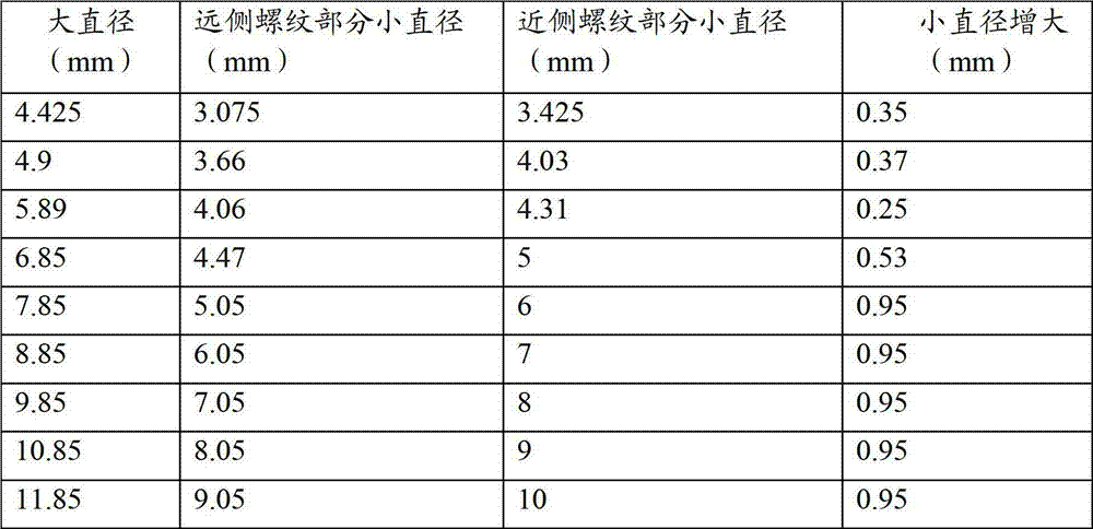
远侧螺纹部分22和近侧螺纹部分24的大直径和小直径可根椐骨锚12将要插入的骨骼进行选择。例如,对于设计成插入穿过腰椎或胸椎的椎弓根的骨锚(例如示例性骨锚12),远侧螺纹部分22和近侧螺纹部分24的大直径可介于4mm和10mm之间。在示例性实施方案中,远侧螺纹部分22的大直径和近侧螺纹部分24的大直径相等且在远侧螺纹部分22和近侧螺纹部分24的轴向长度上是恒定的。在示例性实施方案中,近侧螺纹部分24的小直径大于远侧螺纹部分22的小直径。近侧螺纹部分24的增大的小直径为近侧螺纹部分24提供减小的螺纹深度,这通过压缩脊骨的椎弓根的骨骼而增强了骨骼的抓紧。远侧螺纹部分22的小直径在远侧螺纹部分22的轴向长度上是恒定的,并且近侧螺纹部分24的小直径在近侧螺纹部分24的轴向长度上是恒定的。小直径可从远侧螺纹部分22到近侧螺纹部分24逐步地或逐渐地增大。表2提供了远侧螺纹部分22和近侧螺纹部分24的示例性的大直径和小直径。The major and minor diameters of distal threaded
表2: Table 2 :
在可供选择的实施方案中,远侧螺纹部分22的小直径和近侧螺纹部分24的小直径可以是相等的,并且远侧螺纹部分22和近侧螺纹部分24的小直径在轴向长度上是恒定的。In an alternative embodiment, the minor diameter of the distal threaded
在可供选择的实施方案中,近侧螺纹部分24的大直径可大于远侧螺纹部分22的大直径。大直径可从远侧螺纹部分22到近侧螺纹部分24逐步地或逐渐地增大。In alternative embodiments, the major diameter of the proximal threaded
虽然本发明的装置和方法已结合其示例性实施方案具体加以示出和描述,但本领域的普通技术人员应当理解,在不脱离本发明的精神和范围的前提下,可按照本文所述形式和细节进行各种修改。只采用常规实验,本领域的普通技术人员将会认识到或能够确定本文具体所描述的示例性实施方案的许多等同形式。这种等同形式旨在由本发明和所附权利要求的范围来涵盖。While the apparatus and method of the present invention have been shown and described in detail in conjunction with exemplary embodiments thereof, it should be understood by those of ordinary skill in the art that modifications may be made in the forms described herein without departing from the spirit and scope of the invention. and details with various modifications. Those skilled in the art will recognize, or be able to ascertain, using no more than routine experimentation, many equivalents to the exemplary embodiments specifically described herein. Such equivalents are intended to be covered by the scope of this invention and appended claims.
Claims (15)
Applications Claiming Priority (3)
| Application Number | Priority Date | Filing Date | Title |
|---|---|---|---|
| US34615710P | 2010-05-19 | 2010-05-19 | |
| US61/346157 | 2010-05-19 | ||
| PCT/US2011/036966 WO2011146593A1 (en) | 2010-05-19 | 2011-05-18 | Bone anchors |
Publications (2)
| Publication Number | Publication Date |
|---|---|
| CN102905636A true CN102905636A (en) | 2013-01-30 |
| CN102905636B CN102905636B (en) | 2016-05-18 |
Family
ID=44973107
Family Applications (1)
| Application Number | Title | Priority Date | Filing Date |
|---|---|---|---|
| CN201180024807.3A Active CN102905636B (en) | 2010-05-19 | 2011-05-18 | Bone anchor |
Country Status (7)
| Country | Link |
|---|---|
| US (1) | US20110288599A1 (en) |
| EP (1) | EP2571435A4 (en) |
| JP (1) | JP5797748B2 (en) |
| CN (1) | CN102905636B (en) |
| AU (1) | AU2011256194A1 (en) |
| CA (1) | CA2799758A1 (en) |
| WO (1) | WO2011146593A1 (en) |
Cited By (9)
| Publication number | Priority date | Publication date | Assignee | Title |
|---|---|---|---|---|
| CN104970876A (en) * | 2015-05-06 | 2015-10-14 | 宁德市闽东医院 | Metal spicule |
| CN105263440A (en) * | 2013-04-09 | 2016-01-20 | 史密夫和内修有限公司 | Open-architecture interference screw |
| US9579189B2 (en) | 2007-08-16 | 2017-02-28 | Smith & Nephew, Inc. | Helicoil interference fixation system for attaching a graft ligament to a bone |
| US9579188B2 (en) | 2010-03-10 | 2017-02-28 | Smith & Nephew, Inc. | Anchor having a controlled driver orientation |
| US9775702B2 (en) | 2010-03-10 | 2017-10-03 | Smith & Nephew, Inc. | Composite interference screws and drivers |
| US9788828B2 (en) | 2013-03-15 | 2017-10-17 | Smith & Nephew, Inc. | Miniaturized dual drive open architecture suture anchor |
| US9808337B2 (en) | 2010-03-10 | 2017-11-07 | Smith & Nephew, Inc. | Composite interference screws and drivers |
| US9901355B2 (en) | 2011-03-11 | 2018-02-27 | Smith & Nephew, Inc. | Trephine |
| US9924934B2 (en) | 2011-06-07 | 2018-03-27 | Smith & Nephew, Inc. | Surgical anchor delivery system |
Families Citing this family (58)
| Publication number | Priority date | Publication date | Assignee | Title |
|---|---|---|---|---|
| US8007522B2 (en) | 2008-02-04 | 2011-08-30 | Depuy Spine, Inc. | Methods for correction of spinal deformities |
| US20140012322A1 (en) * | 2008-10-10 | 2014-01-09 | Brian Gayvey | Bone Screw |
| CA2742077A1 (en) | 2008-10-30 | 2010-05-06 | Depuy Spine, Inc. | Systems and methods for delivering bone cement to a bone anchor |
| RU2712028C2 (en) * | 2009-11-09 | 2020-01-24 | Спайнуэлдинг Аг | Medical device for implantation into human or animal body or for strengthening of human or animal solid tissue for further implantation of separate implant and dental implant |
| US8641717B2 (en) | 2010-07-01 | 2014-02-04 | DePuy Synthes Products, LLC | Guidewire insertion methods and devices |
| US9265620B2 (en) * | 2011-03-18 | 2016-02-23 | Raed M. Ali, M.D., Inc. | Devices and methods for transpedicular stabilization of the spine |
| US9155580B2 (en) | 2011-08-25 | 2015-10-13 | Medos International Sarl | Multi-threaded cannulated bone anchors |
| US20140058461A1 (en) * | 2012-08-27 | 2014-02-27 | Michael Black | Fenestrated Bone Screw |
| DE102013001933B4 (en) * | 2012-09-07 | 2017-09-14 | Human Tech Germany Gmbh | Bone screw for fixation of a bone screw rod system |
| US9782204B2 (en) | 2012-09-28 | 2017-10-10 | Medos International Sarl | Bone anchor assemblies |
| US9782209B2 (en) * | 2012-10-03 | 2017-10-10 | Rtg Scientific | Medical fastener |
| WO2014088522A2 (en) * | 2012-12-07 | 2014-06-12 | Spi̇namer Sağlik Ürünleri̇ Sanayi̇ Ve Teknoloji̇ Li̇mi̇ted Şi̇rketi̇ | Ortovia spinal system |
| DE102013202065B4 (en) * | 2013-02-08 | 2017-09-07 | Silony Medical International AG | osteosynthesis |
| US20140277159A1 (en) | 2013-03-14 | 2014-09-18 | DePuy Synthes Products, LLC | Bottom-loading bone anchor assemblies |
| US9724145B2 (en) | 2013-03-14 | 2017-08-08 | Medos International Sarl | Bone anchor assemblies with multiple component bottom loading bone anchors |
| US20140277153A1 (en) | 2013-03-14 | 2014-09-18 | DePuy Synthes Products, LLC | Bone Anchor Assemblies and Methods With Improved Locking |
| US9861495B2 (en) | 2013-03-14 | 2018-01-09 | Raed M. Ali, M.D., Inc. | Lateral interbody fusion devices, systems and methods |
| US10342582B2 (en) | 2013-03-14 | 2019-07-09 | DePuy Synthes Products, Inc. | Bone anchor assemblies and methods with improved locking |
| US9433445B2 (en) | 2013-03-14 | 2016-09-06 | DePuy Synthes Products, Inc. | Bone anchors and surgical instruments with integrated guide tips |
| US9775660B2 (en) | 2013-03-14 | 2017-10-03 | DePuy Synthes Products, Inc. | Bottom-loading bone anchor assemblies and methods |
| US9259247B2 (en) | 2013-03-14 | 2016-02-16 | Medos International Sarl | Locking compression members for use with bone anchor assemblies and methods |
| US20150094769A1 (en) | 2013-10-01 | 2015-04-02 | Hamid Abbasi | System and method for lengthening an existing spinal support structure |
| US20150265318A1 (en) * | 2014-03-20 | 2015-09-24 | Hamid Abbasi | System for enhancing bone growth on orthopedic implants |
| US9855087B2 (en) | 2014-08-04 | 2018-01-02 | DePuy Synthes Products, LLC | Methods and devices for spinal screw insertion |
| US10085786B2 (en) | 2015-04-13 | 2018-10-02 | Medos International Sàrl | Driver instruments and related methods |
| DE202015003062U1 (en) * | 2015-04-25 | 2016-07-27 | Silony Medical International AG | Monoaxialknochenschraube |
| DE102015008036A1 (en) * | 2015-06-09 | 2016-12-15 | Signus Medizintechnik Gmbh | Pedicle screw with tulip |
| US9949731B2 (en) | 2015-10-07 | 2018-04-24 | Medos International Sàrl | Systems and methods for manipulating bone |
| US10188430B2 (en) * | 2015-11-16 | 2019-01-29 | Clariance | Double-threaded bone screw |
| FR3046534B1 (en) * | 2016-01-13 | 2021-12-10 | Neuro France Implants | IMPLANT DEVICE |
| US9962192B2 (en) | 2016-03-17 | 2018-05-08 | Medos International Sarl | Multipoint fixation implants |
| CN105963006A (en) * | 2016-04-22 | 2016-09-28 | 深圳市斯玛仪器有限公司 | Vertebral pedicle fixator and fixing system |
| US10463402B2 (en) | 2016-07-13 | 2019-11-05 | Medos International Sàrl | Bone anchor assemblies and related instrumentation |
| US10874438B2 (en) | 2016-07-13 | 2020-12-29 | Medos International Sarl | Bone anchor assemblies and related instrumentation |
| US10568667B2 (en) | 2016-07-13 | 2020-02-25 | Medos International Sàrl | Bone anchor assemblies and related instrumentation |
| US10363073B2 (en) | 2016-07-13 | 2019-07-30 | Medos International Sàrl | Bone anchor assemblies and related instrumentation |
| US10485596B2 (en) | 2016-12-06 | 2019-11-26 | Medos International Sàrl | Longitudinally-adjustable bone anchors and related methods |
| US10441326B2 (en) | 2016-12-23 | 2019-10-15 | Medos International Sérl | Driver instruments and related methods |
| US10653457B2 (en) | 2017-02-01 | 2020-05-19 | Medos International Sarl | Multi-function driver instruments and related methods |
| US11147602B2 (en) * | 2017-05-04 | 2021-10-19 | Warsaw Orthopedic, Inc. | Spinal implant system and method |
| US11026730B2 (en) | 2017-05-10 | 2021-06-08 | Medos International Sarl | Bone anchors with drag features and related methods |
| US11376050B2 (en) | 2017-06-27 | 2022-07-05 | Medos International Sarl | Bone screw |
| US10433883B2 (en) | 2017-06-27 | 2019-10-08 | Medos International Sarl | Spinal screw insertion devices and methods |
| CN107320168A (en) * | 2017-08-03 | 2017-11-07 | 大博医疗科技股份有限公司 | Femur fixing device |
| US10610269B2 (en) | 2017-09-05 | 2020-04-07 | Medos International Sarl | Modular surgical instruments and related methods |
| US10779872B2 (en) | 2017-11-02 | 2020-09-22 | Medos International Sarl | Bone anchor insertion instruments and methods |
| US10772667B2 (en) | 2017-12-22 | 2020-09-15 | Medos International Sarl | Bone screw with cutting tip |
| US10898232B2 (en) | 2018-03-20 | 2021-01-26 | Medos International Sàrl | Multipoint fixation implants and related methods |
| CN109620382A (en) * | 2019-01-18 | 2019-04-16 | 贝尔泰克医疗器械江苏有限公司 | A kind of pedicle screw |
| US11426210B2 (en) | 2019-09-25 | 2022-08-30 | Medos International Sàrl | Multipoint angled fixation implants for multiple screws and related methods |
| US11653953B2 (en) | 2019-10-11 | 2023-05-23 | Medos International Sarl | Implant receivers and connectors with grip grooves for rod fixation |
| AU2021220225A1 (en) | 2020-02-14 | 2022-10-06 | Medos International Sarl | Integrated multipoint fixation screw |
| WO2022184797A1 (en) | 2021-03-05 | 2022-09-09 | Medos International Sarl | Selectively locking polyaxial screw |
| CN116916839A (en) | 2021-03-05 | 2023-10-20 | 美多斯国际有限公司 | Sequencer |
| US12310631B2 (en) | 2021-03-05 | 2025-05-27 | Medos International Sárl | Multi-feature polyaxial screw |
| US11439437B1 (en) | 2021-06-09 | 2022-09-13 | Medos International Sarl | Bottom loading bone anchor assemblies with drag retaining ring and related methods |
| US12527609B2 (en) | 2022-01-14 | 2026-01-20 | Medos International Sàrl | Implant containers and related methods |
| KR102733824B1 (en) * | 2023-08-25 | 2024-11-25 | 박경우 | Bio-flexible spinal implant assembly with detachable head modules and their continuous connection assembly |
Citations (6)
| Publication number | Priority date | Publication date | Assignee | Title |
|---|---|---|---|---|
| WO2002083015A1 (en) * | 2001-04-16 | 2002-10-24 | Smith & Nephew Inc. | Orthopedic screw and method of use |
| US6565566B1 (en) * | 2000-03-22 | 2003-05-20 | Spinal Concepts, Inc. | Sacral screw assembly and method |
| US20040006346A1 (en) * | 2001-08-15 | 2004-01-08 | Anders Holmen | Implant, arrangement comprising an implant, and method for inserting said implant in bone tissue |
| CN101185587A (en) * | 2006-11-22 | 2008-05-28 | 比德曼莫泰赫有限公司 | Bone anchoring device |
| CN101394802A (en) * | 2006-02-16 | 2009-03-25 | 华沙整形外科股份有限公司 | multithreaded bone screw |
| CN101528143A (en) * | 2006-10-26 | 2009-09-09 | 华沙整形外科股份有限公司 | Bone screw |
Family Cites Families (13)
| Publication number | Priority date | Publication date | Assignee | Title |
|---|---|---|---|---|
| US3018A (en) * | 1843-03-21 | Coupling for qttilting-frames | ||
| IT1237496B (en) * | 1989-10-26 | 1993-06-08 | Giuseppe Vrespa | SCREW DEVICE FOR ANCHORING BONE PROSTHESES, METHOD FOR THE APPLICATION OF SUCH DEVICE AND RELATED EQUIPMENT |
| SE9802571D0 (en) * | 1998-07-17 | 1998-07-17 | Astra Ab | Implant |
| US20050228388A1 (en) * | 2004-03-30 | 2005-10-13 | Darrel Brodke | Double lead bone screw |
| EP1865862B1 (en) * | 2005-04-04 | 2016-08-24 | Zimmer GmbH | Pedicle screw |
| US8821506B2 (en) * | 2006-05-11 | 2014-09-02 | Michael David Mitchell | Bone screw |
| US20090198291A1 (en) * | 2006-10-26 | 2009-08-06 | Warsaw Orthopedic, Inc. | Bone screw |
| DE602008002815D1 (en) * | 2008-03-28 | 2010-11-11 | Biedermann Motech Gmbh | Bone anchoring device |
| US20100094352A1 (en) * | 2008-10-10 | 2010-04-15 | Andrew Iott | Bone screw |
| CA2742077A1 (en) * | 2008-10-30 | 2010-05-06 | Depuy Spine, Inc. | Systems and methods for delivering bone cement to a bone anchor |
| US9247967B2 (en) * | 2008-12-03 | 2016-02-02 | Warsaw Orthopedic, Inc. | Rod and anchor system and method for using |
| US20100274295A1 (en) * | 2009-04-24 | 2010-10-28 | Warsaw Orthopedic, Inc. | Medical implant configured to deliver a therapeutic substance |
| US8419779B2 (en) * | 2009-12-08 | 2013-04-16 | James A. Rinner | Systematic displacement bone screw |
-
2011
- 2011-05-18 EP EP11784154.4A patent/EP2571435A4/en not_active Withdrawn
- 2011-05-18 US US13/110,378 patent/US20110288599A1/en not_active Abandoned
- 2011-05-18 CN CN201180024807.3A patent/CN102905636B/en active Active
- 2011-05-18 JP JP2013511324A patent/JP5797748B2/en active Active
- 2011-05-18 AU AU2011256194A patent/AU2011256194A1/en not_active Abandoned
- 2011-05-18 WO PCT/US2011/036966 patent/WO2011146593A1/en not_active Ceased
- 2011-05-18 CA CA2799758A patent/CA2799758A1/en not_active Abandoned
Patent Citations (7)
| Publication number | Priority date | Publication date | Assignee | Title |
|---|---|---|---|---|
| US6565566B1 (en) * | 2000-03-22 | 2003-05-20 | Spinal Concepts, Inc. | Sacral screw assembly and method |
| WO2002083015A1 (en) * | 2001-04-16 | 2002-10-24 | Smith & Nephew Inc. | Orthopedic screw and method of use |
| US6565573B1 (en) * | 2001-04-16 | 2003-05-20 | Smith & Nephew, Inc. | Orthopedic screw and method of use |
| US20040006346A1 (en) * | 2001-08-15 | 2004-01-08 | Anders Holmen | Implant, arrangement comprising an implant, and method for inserting said implant in bone tissue |
| CN101394802A (en) * | 2006-02-16 | 2009-03-25 | 华沙整形外科股份有限公司 | multithreaded bone screw |
| CN101528143A (en) * | 2006-10-26 | 2009-09-09 | 华沙整形外科股份有限公司 | Bone screw |
| CN101185587A (en) * | 2006-11-22 | 2008-05-28 | 比德曼莫泰赫有限公司 | Bone anchoring device |
Cited By (12)
| Publication number | Priority date | Publication date | Assignee | Title |
|---|---|---|---|---|
| US9579189B2 (en) | 2007-08-16 | 2017-02-28 | Smith & Nephew, Inc. | Helicoil interference fixation system for attaching a graft ligament to a bone |
| US9579188B2 (en) | 2010-03-10 | 2017-02-28 | Smith & Nephew, Inc. | Anchor having a controlled driver orientation |
| US9775702B2 (en) | 2010-03-10 | 2017-10-03 | Smith & Nephew, Inc. | Composite interference screws and drivers |
| US9788935B2 (en) | 2010-03-10 | 2017-10-17 | Smith & Nephew, Inc. | Composite interference screws and drivers |
| US9808337B2 (en) | 2010-03-10 | 2017-11-07 | Smith & Nephew, Inc. | Composite interference screws and drivers |
| US9931195B2 (en) | 2010-03-10 | 2018-04-03 | Smith & Nephew, Inc. | Composite interference screws and drivers |
| US9901355B2 (en) | 2011-03-11 | 2018-02-27 | Smith & Nephew, Inc. | Trephine |
| US9924934B2 (en) | 2011-06-07 | 2018-03-27 | Smith & Nephew, Inc. | Surgical anchor delivery system |
| US9788828B2 (en) | 2013-03-15 | 2017-10-17 | Smith & Nephew, Inc. | Miniaturized dual drive open architecture suture anchor |
| CN105263440A (en) * | 2013-04-09 | 2016-01-20 | 史密夫和内修有限公司 | Open-architecture interference screw |
| US9808298B2 (en) | 2013-04-09 | 2017-11-07 | Smith & Nephew, Inc. | Open-architecture interference screw |
| CN104970876A (en) * | 2015-05-06 | 2015-10-14 | 宁德市闽东医院 | Metal spicule |
Also Published As
| Publication number | Publication date |
|---|---|
| JP5797748B2 (en) | 2015-10-21 |
| AU2011256194A1 (en) | 2013-01-10 |
| EP2571435A4 (en) | 2014-09-17 |
| CN102905636B (en) | 2016-05-18 |
| CA2799758A1 (en) | 2011-11-24 |
| WO2011146593A1 (en) | 2011-11-24 |
| JP2013526374A (en) | 2013-06-24 |
| EP2571435A1 (en) | 2013-03-27 |
| US20110288599A1 (en) | 2011-11-24 |
Similar Documents
| Publication | Publication Date | Title |
|---|---|---|
| CN102905636B (en) | Bone anchor | |
| US20250107832A1 (en) | Bone anchors | |
| US10786284B2 (en) | Bone anchor assemblies | |
| EP2765934B1 (en) | Bone anchor assemblies | |
| JP2013526374A5 (en) | ||
| US12150679B2 (en) | Offset rods, offset rod connectors, and related methods | |
| US20130085534A1 (en) | Connectors for a secondary bone anchor | |
| CN102458279B (en) | Revision Connectors for Spine Structures | |
| US9649133B2 (en) | Supplemental fixation screw | |
| JP2007530216A (en) | Double lead bone screw | |
| CN103190948A (en) | Internal vertebra fixing device |
Legal Events
| Date | Code | Title | Description |
|---|---|---|---|
| C06 | Publication | ||
| PB01 | Publication | ||
| C10 | Entry into substantive examination | ||
| SE01 | Entry into force of request for substantive examination | ||
| C14 | Grant of patent or utility model | ||
| GR01 | Patent grant |