CN102897655A - a decoupling device - Google Patents
a decoupling device Download PDFInfo
- Publication number
- CN102897655A CN102897655A CN2011104602726A CN201110460272A CN102897655A CN 102897655 A CN102897655 A CN 102897655A CN 2011104602726 A CN2011104602726 A CN 2011104602726A CN 201110460272 A CN201110460272 A CN 201110460272A CN 102897655 A CN102897655 A CN 102897655A
- Authority
- CN
- China
- Prior art keywords
- hook
- pin
- connecting rod
- bracket
- pin shaft
- Prior art date
- Legal status (The legal status is an assumption and is not a legal conclusion. Google has not performed a legal analysis and makes no representation as to the accuracy of the status listed.)
- Granted
Links
Images


Landscapes
- Hooks, Suction Cups, And Attachment By Adhesive Means (AREA)
Abstract
Description
(一)技术领域(1) Technical field
本发明涉及一种脱钩装置。The invention relates to a decoupling device.
(二)背景技术(2) Background technology
随着工程技术的不断发展,起重设备载荷挂钩的使用状态也相应有所改变。例如,起吊一载荷,将其悬空释放,冲击下方相应位置的承力物,或者进行落体试验过程中需要将落体进行释放。通常利用单个一般起重设备配备的挂钩,如挂钩较浅,常发生意外脱落事故,如持钩较深,则难以将载荷或落体释放,如强制释放,将会产生很大的水平分力和反力冲击,使载荷下落时失稳,或连着挂钩的钢丝绳和挂钩在突然失去载荷时发生回弹,易于损伤操作设备。With the continuous development of engineering technology, the use status of the load hook of lifting equipment has also changed accordingly. For example, lifting a load, releasing it in the air, impacting the load-bearing object at the corresponding position below, or releasing the falling object during the drop test. Usually, a single hook equipped with general lifting equipment is used. If the hook is shallow, accidental falling accidents often occur. If the hook is deep, it is difficult to release the load or fall. If it is forced to release, it will generate a large horizontal force and force. The impact of the counter force makes the load unstable when it falls, or the steel wire rope and the hook connected to the hook rebound when the load is suddenly lost, which is easy to damage the operating equipment.
(三)发明内容(3) Contents of the invention
为了弥补以上不足,本发明提供一种装置结构简单,操作方便的脱钩装置。In order to make up for the above deficiencies, the present invention provides a decoupling device with simple structure and convenient operation.
本发明采用如下方案:一种脱钩装置,包括支架、第一销轴、第一挂钩和提拉机构,第一挂钩通过第一销轴铰接在支架上,所述提拉机构与第一挂钩连接,在提拉机构的作用下,第一挂钩绕第一销轴转动,其特征在于:脱钩装置还包括第二销轴和第二挂钩,第二挂钩通过第二销轴铰接在支架上,所述第一销轴上固定安装有第一齿轮,第二销轴上固定安装有第二齿轮,第一齿轮和第二齿轮啮合传动,第一挂钩和第二挂钩的一端各自设有第一钩舌和第二钩舌,第一钩舌和第二钩舌相错开且侧面相互紧靠形成钩物空间。The present invention adopts the following scheme: a decoupling device, including a bracket, a first pin shaft, a first hook and a lifting mechanism, the first hook is hinged on the bracket through the first pin shaft, and the lifting mechanism is connected to the first hook , under the action of the pulling mechanism, the first hook rotates around the first pin shaft, and it is characterized in that: the decoupling device also includes a second pin shaft and a second hook, and the second hook is hinged on the bracket through the second pin shaft, so The first gear is fixedly installed on the first pin shaft, the second gear is fixedly installed on the second pin shaft, the first gear and the second gear are meshed for transmission, and one end of the first hook and the second hook is respectively provided with a first hook The tongue and the second knuckle, the first knuckle and the second knuckle are staggered and the sides are close to each other to form a hook space.
上述的一种脱钩装置,其特征在于:所述第一钩舌设有第一凹位,第二钩舌设有第二凹位,第一凹位与第二凹位相对合并成所述钩物空间。The above-mentioned uncoupling device is characterized in that: the first knuckle is provided with a first concave position, the second knuckle is provided with a second concave position, and the first concave position and the second concave position are relatively combined to form the hook object space.
上述的一种脱钩装置,其特征在于:所述提拉机构包括第一连杆、第二连杆、第三销轴、制动杆和防转圆柱销;The above-mentioned uncoupling device is characterized in that: the pulling mechanism includes a first connecting rod, a second connecting rod, a third pin shaft, a brake lever and an anti-rotation cylindrical pin;
所述第一挂钩远离所述第一钩舌的一端与第一连杆的一端铰接,第一连杆的另一端通过第三销轴铰接在制动杆的中间,第二连杆的一端铰接在支架上,第二连杆设有滑槽,防转圆柱销固定安装在制动杆的一端,防转圆柱销安装在滑槽上;One end of the first hook away from the first knuckle is hinged to one end of the first connecting rod, the other end of the first connecting rod is hinged in the middle of the brake lever through a third pin, and one end of the second connecting rod is hinged On the bracket, the second connecting rod is provided with a chute, the anti-rotation cylindrical pin is fixedly installed at one end of the brake lever, and the anti-rotation cylindrical pin is installed on the chute;
所述滑槽为平行槽和圆孔拼接成一体,防转圆柱销的中间设有两个平位,两个平位的底面相平行,两个平位的底面间距小于所述平行槽的间隙,防转圆柱销在滑槽的圆孔处可绕圆孔的中心轴转动,防转圆柱销在滑槽的平行槽处时防转圆柱销卡在平行槽内,使第二连杆随制动杆同步动作。The chute is a combination of parallel grooves and round holes. There are two flat positions in the middle of the anti-rotation cylindrical pin. The bottom surfaces of the two flat positions are parallel, and the distance between the bottom surfaces of the two flat positions is smaller than the gap between the parallel grooves. , the anti-rotation cylindrical pin can rotate around the central axis of the round hole at the round hole of the chute. When the anti-rotation cylindrical pin is at the parallel groove of the chute, the anti-rotation cylindrical pin is stuck in the parallel groove, so that the second connecting rod follows The moving rod moves synchronously.
上述的一种脱钩装置,其特征在于:所述第二连杆上设有挡止部与所述第三销轴相对应。The above-mentioned uncoupling device is characterized in that: the second connecting rod is provided with a stopper corresponding to the third pin.
上述的一种脱钩装置,其特征在于:所述支架两侧向外对称伸出两根支撑杆,支撑杆上安装有滚轮导靴。The above-mentioned decoupling device is characterized in that: two support rods protrude symmetrically outward from both sides of the bracket, and roller guide shoes are installed on the support rods.
上述的一种脱钩装置,其特征在于:所述支架包括左支架、右支架、连接轴及若干撑杆,所述连接轴连接左支架和右支架并位于其上端,左支架和右支架通过若干撑杆组装成一体。The above-mentioned uncoupling device is characterized in that: the bracket includes a left bracket, a right bracket, a connecting shaft and several struts, the connecting shaft connects the left bracket and the right bracket and is located at its upper end, and the left bracket and the right bracket pass through several The struts are assembled into one piece.
本发明的优点在于:采用齿轮联动双挂钩的方式,克服了释放载荷时使载荷下落时失稳,或连着挂钩的钢丝绳和挂钩在突然失去载荷时发生回弹,保护操作设备,而且装置结构简单,操作方便。The advantage of the present invention is that: the way of gear linkage double hooks is adopted to overcome the instability of the load when the load is released, or the rebound of the steel wire rope and the hook connected to the hook when the load is suddenly lost, so as to protect the operating equipment and the device structure Simple and easy to operate.
(四)附图说明(4) Description of drawings
图1为本发明的立体示意图;Fig. 1 is the three-dimensional schematic diagram of the present invention;
图2为本发明的爆炸示意图;Fig. 2 is the explosion schematic diagram of the present invention;
图3是第二连杆与制动杆分离状态示意图;Fig. 3 is a schematic diagram of the separation state of the second connecting rod and the brake lever;
图4是本发明待机状态示意图;Fig. 4 is a schematic diagram of the standby state of the present invention;
图5是本发明准备状态示意图;Fig. 5 is a schematic diagram of the present invention's ready state;
图6是本发明开始状态示意图;Fig. 6 is a schematic diagram of the starting state of the present invention;
图7是本发明工作状态示意图。Fig. 7 is a schematic diagram of the working state of the present invention.
(五)具体实施方式(5) Specific implementation methods
下面结合附图对本发明作进一步详细的说明。The present invention will be described in further detail below in conjunction with the accompanying drawings.
实施例:如图1至图7所示的一种脱钩装置,包括支架1、第一销轴2-1、第二销轴3-1、第一挂钩2-2、第二挂钩3-2和提拉机构,第一挂钩2-2通过第一销轴2-1铰接在支架1上,第二挂钩3-2通过第二销轴3-1铰接在支架1上,提拉机构与第一挂钩2-2连接,在提拉机构的作用下,第一挂钩2-2绕第一销轴2-1转动,所述第一销轴2-1上固定安装有第一齿轮2-3,第二销轴3-1上固定安装有第二齿轮3-3,第一齿轮2-3和第二齿轮3-3啮合传动,第一挂钩2-2和第二挂钩3-2的一端各自设有第一钩舌2-4和第二钩舌3-4,第一钩舌2-4设有第一凹位2-5,第二钩舌3-4设有第二凹位3-5,第一钩舌2-4和第二钩舌3-4相错开且侧面相互紧靠使第一凹位2-5与第二凹位3-5相对合并成钩物空间。采用齿轮联动双挂钩的方式,克服了释放载荷时使载荷下落时失稳,或连着挂钩的钢丝绳和挂钩在突然失去载荷时发生回弹,保护操作设备。Embodiment: a decoupling device as shown in Figures 1 to 7, including a bracket 1, a first pin shaft 2-1, a second pin shaft 3-1, a first hook 2-2, and a second hook 3-2 and the lifting mechanism, the first hook 2-2 is hinged on the bracket 1 through the first pin shaft 2-1, the second hook 3-2 is hinged on the bracket 1 through the second pin shaft 3-1, and the lifting mechanism is connected with the first pin shaft 3-1. A hook 2-2 is connected, and under the action of the lifting mechanism, the first hook 2-2 rotates around the first pin shaft 2-1, and the first gear 2-3 is fixedly installed on the first pin shaft 2-1 , the second pin shaft 3-1 is fixedly installed with the second gear 3-3, the first gear 2-3 and the second gear 3-3 mesh transmission, one end of the first hook 2-2 and the second hook 3-2 Each is provided with a first knuckle 2-4 and a second knuckle 3-4, the first knuckle 2-4 is provided with a first recess 2-5, and the second knuckle 3-4 is provided with a second recess 3 -5, the first knuckle tongue 2-4 and the second knuckle tongue 3-4 are staggered and the sides are close to each other so that the first concave position 2-5 and the second concave position 3-5 are relatively merged into a hook space. The gear-linked double-hook method overcomes the instability of the load when the load is released, or the rebound of the wire rope and the hook connected to the hook when the load is suddenly lost, protecting the operating equipment.
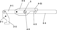
提拉机构包括第一连杆4-1、第二连杆4-2、第三销轴4-3、制动杆4-4和防转圆柱销4-5。第一挂钩2-2远离所述第一钩舌2-4的一端与第一连杆4-1的一端铰接,第一连杆4-1的另一端通过第三销轴4-3铰接在制动杆4-4的中间,第二连杆4-2的一端铰接在支架1上,第二连杆4-2设有滑槽5,防转圆柱销4-5固定安装在制动杆4-4的一端,防转圆柱销4-5安装在滑槽5上。所述滑槽5为平行槽5-1和圆孔5-2拼接成一体,防转圆柱销4-5的中间设有两个平位,两个平位的底面相平行,两个平位的底面间距小于所述平行槽5-1的间隙,防转圆柱销4-5在滑槽的圆孔5-2处可绕圆孔5-2的中心轴转动,防转圆柱销4-5在滑槽5的平行槽5-1处时防转圆柱销4-5卡在平行槽5-1内,使第二连杆4-2随制动杆4-4同步动作。第二连杆4-2上还设有挡止部4-21与所述第三销轴4-3相对应,使制动杆4-4上提时不只防转圆柱销4-5处受力,而且在挡止部4-21处受力,分散受力点,节省了制动杆4-4向上提拉力,保护防转圆柱销4-5的受力面。The pulling mechanism includes a first connecting rod 4-1, a second connecting rod 4-2, a third pin shaft 4-3, a brake lever 4-4 and an anti-rotation cylindrical pin 4-5. One end of the first hook 2-2 away from the first knuckle tongue 2-4 is hinged with one end of the first connecting rod 4-1, and the other end of the first connecting rod 4-1 is hinged at the third pin shaft 4-3. In the middle of the brake rod 4-4, one end of the second connecting rod 4-2 is hinged on the bracket 1, the second connecting rod 4-2 is provided with a
支架1包括左支架1-1、右支架1-2、连接轴1-3及若干撑杆1-4,所述连接轴1-3连接左支架1-1和右支架1-2并位于其上端,撑杆1-4连接左支架1-1和右支架1-2使其固定成一体。左支架1-1、右支架1-2分设向外对称伸出两根支撑杆1-5,支撑杆1-5上安装有滚轮导靴1-6。使用时滚轮导靴1-6与导轨等配合使支架1保持平衡和稳定。Bracket 1 comprises left bracket 1-1, right bracket 1-2, connecting shaft 1-3 and some struts 1-4, and described connecting shaft 1-3 connects left bracket 1-1 and right bracket 1-2 and is positioned at it. At the upper end, the strut 1-4 connects the left support 1-1 and the right support 1-2 to make it fixed as a whole. The left support 1-1 and the right support 1-2 are respectively provided with two support rods 1-5 that are symmetrically stretched out outwards, and roller guide shoes 1-6 are installed on the support rods 1-5. Roller guide shoe 1-6 cooperates with guide rail etc. to keep support 1 balanced and stable during use.
脱钩装置的工作过程如下:如图4至图7所示(图中省去第二挂钩3-2及第一齿轮2-3和第二齿轮3-3),首先处于待机状态,此时制动杆4-4向下倾斜,防转圆柱销4-5位于滑槽5的圆孔5-2处,提拉制动杆4-4的一端,使其可绕滑槽5的圆孔5-2中心轴转动,进入准备状态。在准备状态,重物置于钩物空间,连接轴1-3上连接一起重装置使支架1稍微上升产生一个向上的拉力,在该拉力和在重物的重力共同作用下,第一挂钩2-2绕第一销轴2-1转动,带动第一齿轮2-3的同时带动第二齿轮3-3,使第二挂钩3-2绕第二销轴3-1转动,使第一钩舌2-4和第二钩舌3-4的第一凹位2-5与第二凹位3-5相对合并成钩物空间,抓紧重物。同时由于第一挂钩2-2的转动,使第一连杆4-1产生向右的一个作用力,推动防转圆柱销4-5进入滑槽5的平行槽5-1处并卡在平行槽5-1内,使第二连杆4-2随制动杆4-4同步动作并进入开始状态。进入开始状态后,继续提拉制动杆4-4的一端,使第二连杆4-2随着上升绕着铰接轴转动,使第一连杆4-1产生一个向左的推力作用于第一挂钩2-2,第一挂钩2-2绕第一销轴2-1转动,带动第一齿轮2-3的同时带动第二齿轮3-3,使第二挂钩3-1绕第二销轴3-1转动,使第一钩舌2-4和第二钩舌3-4相离而释放重物。The working process of the uncoupling device is as follows: as shown in Figure 4 to Figure 7 (save the second hook 3-2 and the first gear 2-3 and the second gear 3-3 among the figures), at first it is in standby mode, and now the system The moving rod 4-4 is inclined downward, and the anti-rotation cylindrical pin 4-5 is positioned at the circular hole 5-2 of the
有必要在此指出的是以上实施方式只用于对本发明进行进一步说明,不能理解为对本发明保护范围的限制,该领域的普通技术人员可以根据本发明的实质对以上实施方式做出一些非本质的改进和调整。It is necessary to point out that the above embodiments are only used to further illustrate the present invention, and should not be interpreted as limiting the protection scope of the present invention. Those of ordinary skill in the art can make some non-essential changes to the above embodiments according to the essence of the present invention. improvements and adjustments.
Claims (6)
Priority Applications (1)
| Application Number | Priority Date | Filing Date | Title |
|---|---|---|---|
| CN201110460272.6A CN102897655B (en) | 2011-12-30 | 2011-12-30 | Unhooking device |
Applications Claiming Priority (1)
| Application Number | Priority Date | Filing Date | Title |
|---|---|---|---|
| CN201110460272.6A CN102897655B (en) | 2011-12-30 | 2011-12-30 | Unhooking device |
Publications (2)
| Publication Number | Publication Date |
|---|---|
| CN102897655A true CN102897655A (en) | 2013-01-30 |
| CN102897655B CN102897655B (en) | 2014-06-18 |
Family
ID=47570195
Family Applications (1)
| Application Number | Title | Priority Date | Filing Date |
|---|---|---|---|
| CN201110460272.6A Active CN102897655B (en) | 2011-12-30 | 2011-12-30 | Unhooking device |
Country Status (1)
| Country | Link |
|---|---|
| CN (1) | CN102897655B (en) |
Citations (5)
| Publication number | Priority date | Publication date | Assignee | Title |
|---|---|---|---|---|
| CN2056669U (en) * | 1988-09-29 | 1990-05-02 | 新疆建筑勘察设计院 | Hook with hook separating system |
| US5014870A (en) * | 1989-05-12 | 1991-05-14 | Kinshofer Greiftechnik Gmbh | Container with a handling device |
| CN101948078A (en) * | 2010-09-26 | 2011-01-19 | 江苏省电力设计院 | Clamp unhooking device |
| CN201756405U (en) * | 2010-08-17 | 2011-03-09 | 浙江美科斯叉车有限公司 | Tubular pile lower mold clamp structure |
| CN202429878U (en) * | 2011-12-30 | 2012-09-12 | 中山市奥美森工业技术有限公司 | a decoupling device |
-
2011
- 2011-12-30 CN CN201110460272.6A patent/CN102897655B/en active Active
Patent Citations (5)
| Publication number | Priority date | Publication date | Assignee | Title |
|---|---|---|---|---|
| CN2056669U (en) * | 1988-09-29 | 1990-05-02 | 新疆建筑勘察设计院 | Hook with hook separating system |
| US5014870A (en) * | 1989-05-12 | 1991-05-14 | Kinshofer Greiftechnik Gmbh | Container with a handling device |
| CN201756405U (en) * | 2010-08-17 | 2011-03-09 | 浙江美科斯叉车有限公司 | Tubular pile lower mold clamp structure |
| CN101948078A (en) * | 2010-09-26 | 2011-01-19 | 江苏省电力设计院 | Clamp unhooking device |
| CN202429878U (en) * | 2011-12-30 | 2012-09-12 | 中山市奥美森工业技术有限公司 | a decoupling device |
Also Published As
| Publication number | Publication date |
|---|---|
| CN102897655B (en) | 2014-06-18 |
Similar Documents
| Publication | Publication Date | Title |
|---|---|---|
| CN106932187B (en) | Device and method for testing protruding of nose landing gear of carrier-based aircraft | |
| CN105757625B (en) | The high mast lighting jacking system of speed limit fall arrest | |
| CN101973484A (en) | Self-releasing hook | |
| CN204689396U (en) | A kind of roll bending lifting suspension hook | |
| CN104760881B (en) | A kind of automatic decoupling device | |
| CN106629286B (en) | drop test tower | |
| CN105003210A (en) | Drill pipe lifting device | |
| CN202429878U (en) | a decoupling device | |
| CN205331183U (en) | Quick detachable wheel hub spindle nose lock nut's locking mechanism | |
| CN204251108U (en) | Gradual weightless safety tongs | |
| CN102897655B (en) | Unhooking device | |
| CN201864464U (en) | Lifting hook capable of unhooking automatically | |
| CN202322118U (en) | Rigid telescopic hydraulic separate counter weight crane | |
| CN203808041U (en) | Automatic counter weight unhooking device | |
| CN201172576Y (en) | Falling proof mechanism for crane hook | |
| CN202916065U (en) | Weight drop impulse measuring device | |
| JP6096335B2 (en) | Equilibrium device for intermediate coupler | |
| CN201882820U (en) | Automatic jacking device for buffer rod of variable-amplitude auxiliary arm of wheel crane | |
| CN112678678A (en) | Weight limiting device and crane comprising same | |
| CN202831598U (en) | Attached-type novel dropping-preventing device of lifting scaffold | |
| CN207684687U (en) | A kind of overhead speed limiter tensioning device | |
| CN205145427U (en) | Ware slowly falls in piston hydraulic pressure | |
| CN204729028U (en) | Drill stem hoisting device | |
| CN203669843U (en) | Pumping unit single-pulley secondary energy storage device | |
| CN204549823U (en) | A kind of automatic decoupling device |
Legal Events
| Date | Code | Title | Description |
|---|---|---|---|
| C06 | Publication | ||
| PB01 | Publication | ||
| C10 | Entry into substantive examination | ||
| SE01 | Entry into force of request for substantive examination | ||
| C14 | Grant of patent or utility model | ||
| GR01 | Patent grant | ||
| ASS | Succession or assignment of patent right |
Owner name: ZHONGSHAN ELEVATOR FACTORY CO., LTD. Free format text: FORMER OWNER: ZHONGSHAN AOMEISEN INDUSTRY TECHNOLOGY CO.,LTD. Effective date: 20140714 |
|
| C41 | Transfer of patent application or patent right or utility model | ||
| TR01 | Transfer of patent right |
Effective date of registration: 20140714 Address after: 528400 Guangdong province Zhongshan City Daxin Road No. 1, five Patentee after: Zhongshan OMS Industrial Co., Ltd. Address before: 528400 Guangdong city of Zhongshan province Yixian science and Technology Industrial Park, Torch Development Zone, nine East Road Patentee before: Zhongshan Aomeisen Industry Technology Co.,Ltd. |
|
| C56 | Change in the name or address of the patentee | ||
| CP01 | Change in the name or title of a patent holder |
Address after: 528400 Guangdong province Zhongshan City Daxin Road No. 1, five Patentee after: Guangdong BOSCH Elevator Co., Ltd. Address before: 528400 Guangdong province Zhongshan City Daxin Road No. 1, five Patentee before: Zhongshan OMS Industrial Co., Ltd. |
|
| TR01 | Transfer of patent right |
Effective date of registration: 20190531 Address after: 528400 Number Trade Building, No. 6 Xiangxing Road, Central District of Zhongshan Torch Development Zone, Guangdong Province, 2 Building 215 Patentee after: Zhongshan Zhongke intelligent manufacture Research Institute Co., Ltd. Address before: 528400 No. 5 Daxin Road, South District, Zhongshan City, Guangdong Province Patentee before: Guangdong BOSCH Elevator Co., Ltd. |
|
| TR01 | Transfer of patent right |